Embed Size (px)
Citation preview

John Sydor
Siva Palaninathan
Bernard Doray
Jianxing Hu
The Research Broad Band Wireless Group
www.crc.ca/coral
Cognitive Radio Networking in Cognitive Radio Networking in Cognitive Radio Networking in Cognitive Radio Networking in the ISM Bandthe ISM Bandthe ISM Bandthe ISM Band
© 2011 In the Name of the Her Majesty the Queen of Canada

Webinar Overview
� Overview of Cognitive Radio concepts.
� The CRC-CORAL Wi-Fi Cognitive Radio Network Platform.
� Implementation of Cognitive control
� Software for control of sensing and WiFi packet emission in space, time, & channel
� The Radio Environment Awareness Map (REAM):
� Use of Cognitive Engines to control the Network.
� Applications: Dynamic Spectrum Access & Data mining in the REAM
©
Channel Medium
Interference: intensity,
location, propagation
User Population:
distribution
& access behavior
Wireless Network Data Sinks
Radio Layer Emission Control
EIRP, direction, timing, modulation rate, channel,
Radio Environment Sensors, MAC layer protocol
variables
Wireless Network Data
Sources
Radio Layer Reception Control & Performance
Radio Environment Sensors
Uncooperative
Foreign Interferers
Primary User
Cooperative
Interferers
Generic Wireless Network
©

Channel Medium
Interference: intensity,
location, propagation
User Population:
distribution
& access behavior
Wireless Network Data Sinks
Radio Layer Emission Control
EIRP, direction, timing, modulation rate, channel,
Radio Environment Sensors, MAC layer protocol
variables
Wireless Network Data
Sources
ControlCognitive Engine
Statistical Analyzer
Adaptive Intelligence
Data Mining
Performance figure of merit
(Bits/Hz/M2); stability criterion,
bandwidth allocation fairness,etc
Policy or
etiquette, data base
inquiry requirement.
Radio Environment
Sensed Information
Emission & location Information
Radio Resource Requirements
Radio Environment
Map
Radio Layer Reception Control & Performance
Radio Environment SensorsControl
Historical Sensor
Data
Uncooperative
Foreign Interferers
Primary User
Cooperative
InterferersCollaborative
Control
Radio Environment
Sensed Information
Formative Cognitive Radio Architecture
©

Channel Medium
Interference: intensity,
location, propagation
User Population:
distribution
& access behavior
Wireless Network Data Sinks
Radio Layer Emission Control
EIRP, direction, timing, modulation rate, channel,
Radio Environment Sensors, MAC layer protocol
variables
Wireless Network Data
Sources
Cognitive Engine
Statistical Analyzer
Adaptive Intelligence
Data Mining
Performance figure of merit
(Bits/Hz/M2); stability criterion,
bandwidth allocation fairness,etc
Policy or
etiquette, data base
inquiry requirement.
Radio Environment
Map
Radio Layer Reception Control & Performance
Radio Environment Sensors
WiFi_CR Terminal Domain
CR_NMS Domain
©
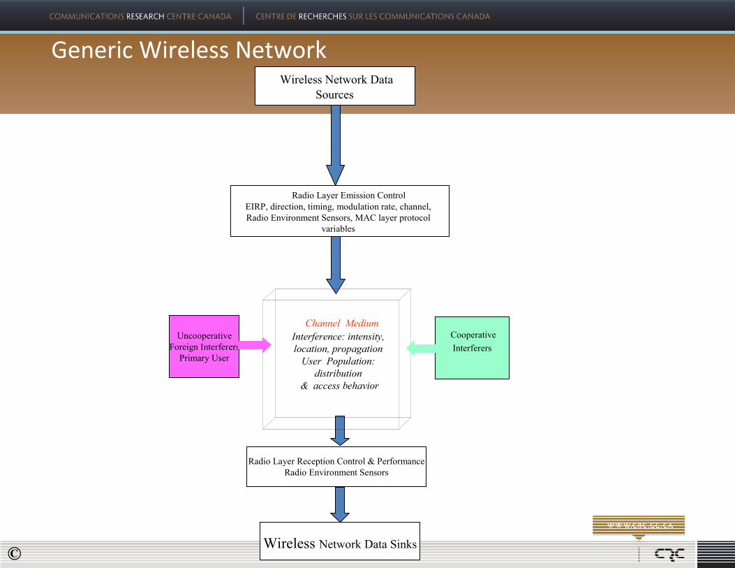
Partitioning the CR
Partitioned Components of CORAL
TCP/IP
WiFi_CR Terminal(Phy/802.11 functions)
CR_NMS(Cognitive Radio
Engines)
©

Single CRN on one CR_NMSTwo CRNs on one CR_NMS
©
Examples of Modular Deployments

4 CRNs on 4 CR_NMS
©
Examples of Modular Deployments

The CRC-CORAL Wi-Fi Cognitive Radio Network Platform
CRC EB Board
CRC Router Board
Radio Cards
Spectrum
Board
19 pin connector
to Break Out Board
Ethernet Connector
to POE Unit
or existing power connection
PoE Unit
GPS
Antenna
2 monopole
2.4 GHz
antennas
Wall/Pole Mounting
Environmentally
Sealed case
WiFi_CR Layout
©

The CRC-CORAL Wi-Fi Cognitive Radio Network Platform
PHY Layer Emission Control
PHY Layer Capabilities of WiFi_CR
�Standard IEEE 802.11g operation, Infrastructure Mode
�TDD/TDMA constrained CSMA/CA
�Per packet beam steering (8 Beams)
�Per Slot antenna beam steering
�Control of EIRP, channel, Ack policy, modulation rate,etc
�GPS, Beacon based, and ARP based TDD slot synchronization
©

Rx
RS232
8 antenna
array
RS232
RF Diversity
RF Diversity
Rx
802.11g Beacon announcement
8 antenna array
Deploymentspecific
RF and detectionsystem modules.
GPS Antenna
WiFi data link radio card.
WiFi sensor radio card.
RF LinkInterface circuits.
8 port RFswitch.
5.5-5.8 GHz RF & steerable
array antenna.
600-700 MHz RF &
steerablearray antenna.
2400-2500 MHz spectrum analyzer.
Antenna Steering/Switch Control.
IEEE 802.3Ethernet
IEEE 802.3Ethernet
RF Tx/Rx
Primary User MatchedFilter detector.
Primary userCyclostationary signal
detector
RF DiversityPort
Rx
RF PortTx/Rx
Ethernet BufferBoard (EBB).
Madwifi4 port
wirelessRouter motherboard.
RF/Tx TDM Control & Framing signals for
control of co-located WIFI_CRAP or Client devices
60 GHz RF & steerable
array antenna.
Diversity8 port RF
switch.
Antenna Switch Option
Omni Antennas
RF/Tx TDM Control &TX power detection.
Dotted lines for
future enhancements
The CRC-CORAL Wi-Fi Cognitive Radio Network Platform
WiFi_CR: block signal processing subsystem layout
©

The CRC-CORAL Wi-Fi Cognitive Radio Network Platform
TDD/TDMA synchronized slots
WiFi TDD with No ACK data transmission between
An Access Point and Client terminal.
TDD Slots
WiFi Packets
AP
CL
©

6 directional Sector/1 omni-sector
Array with diversity.
8X1 RF Switch
MultiMulti--Sector Beam Antenna Sector Beam Antenna
©

Example:Relay and Multiple Beam Steering Configurations
©

Agenda - RouterBoard
� RouterBoard Hardware
� RouterBoard Software
� Wireless Sniffer
©
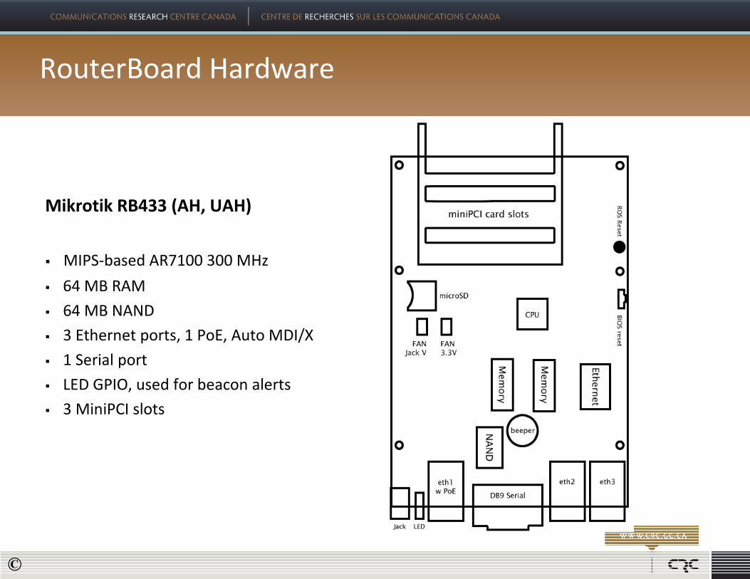
RouterBoard Hardware
Mikrotik RB433 (AH, UAH)
� MIPS-based AR7100 300 MHz
� 64 MB RAM
� 64 MB NAND
� 3 Ethernet ports, 1 PoE, Auto MDI/X
� 1 Serial port
� LED GPIO, used for beacon alerts
� 3 MiniPCI slots
©

RouterBoard Hardware cont.
Wistron CM9 MiniPCI 80211a/b/g
� Atheros AR5212 based
� Infrastructure mode – Link Interface
� Monitor mode – Sniffer Interface
� Madwifi Driver
©

RouterBoard Software
• RouterBOOT Booter
• Linux – Customized OpenWRT
• Modified Madwifi Driver
• NetSNMP
• Wireless sniffer (Kismet Based)
©

RouterBOOT Booter
Available via serial port by pressing DELETE key during boot cycle
� BOOT Device Menu
your choice: o - boot device
Select boot device:
e - boot over Ethernet
* n - boot from NAND, if fail then Ethernet
1 - boot Ethernet once, then NAND
o - boot from NAND only
b - boot chosen device
� Board Info Menu
Board type: 433
Serial number: 21FE01987F32
Firmware version: 2.20
CPU frequency: 300 MHz
Memory size: 64 MB
eth1 MAC address: 00:0C:42:45:27:85
eth2 MAC address: 00:0C:42:45:27:86
eth3 MAC address: 00:0C:42:45:27:87
©

Linux - OpenWRT
• Kernel 2.6.32
• Kamikaze 8_09
• Real time extension
Modifications for CORAL
• GPIO for Beacon alerts
• Various init scripts
©

Madwifi Driver
� Core version r3314
� Latest patches by the development team
� Patches related to cross compilation
Modifications for CORAL
� Beacon notification
� Best effort Q for all type of traffic
� Number of retries
� Diversity enabled
� Deterministic transmission; CCA, backoff
� CTS/RTS Disabling
� Turn ON/OFF ACK policy
©
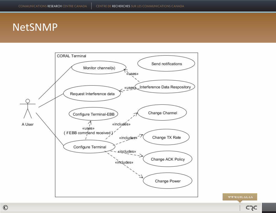
NetSNMP
©

NetSNMP cont.
� Core version 5.1.2
� Version 2
� Latest patches by the development team
� Patches related to cross compilation
Modifications for CORAL
� 802.11 MIB agent implemented/modified
• Handling all radio related configuration commands
• Link related statistics collection
� A new sniffer agent implemented
• Wireless sniffer
• Handling part of EBB communication
• Various CORAL system specific commands
©
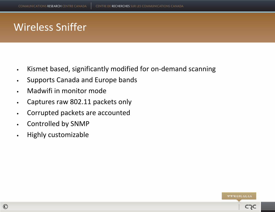
Wireless Sniffer
• Kismet based, significantly modified for on-demand scanning
• Supports Canada and Europe bands
• Madwifi in monitor mode
• Captures raw 802.11 packets only
• Corrupted packets are accounted
• Controlled by SNMP
• Highly customizable
©

Wireless Sniffer – Interference capturing process
• 500 ms per channel
• Interference bins are created for each unique set of:� Source MAC
� Destination MAC
� BSSID
� Channel
� Packet Type
� Packet Subtype
• When a packet is received, its bin is updated with:� timestamp
� number of packets accumulated in the bin
� average RSSI
� packet utilization (packet length/packet transmitted rate)
©

Wireless Sniffer – Interference capturing process cont.
• Information captured from a packet� Captured time; local to system clock
� GPS Location of the sniffer node
� Packet type/subtype
� Sniffer node ID
� TX Duty cycle
� TX Avg
� Channel the packet is detected on
� Channel the sniffer is on
� Source MAC address
� Destination MAC address
� Total duration of packet(s)
� SSID
� RSSI or averaged RSSI
� Number of packets
� Transmit rate of the packet
©

Wireless Sniffer – customization
• Sniffer software can be customized for:
� Packets only from a specific node
� Management, controls or data packets only
� Complete decoded-preamble
� Channel utilization
� Statistics collection: Number of corrupted packets, Retransmission packets, etc
©

Wireless Sniffer cont.
� High CPU usage
� All packets reaching monitor interface are accounted
� Fields extraction
� Utilization calculation
� RAM usage
©

CRNMS
©

CRNMS APICRNMS API
�Interface provided by the CRNMS to control / interrogate
CORAL terminals
�Interface provided to access the REAM data collected by the
CRNMS
�API Available for the following programming languages:
�C, MATLAB, Python
�APIs specified/generated from the WSDL (Web Service
Description Language) specification
©

CRNMS APICRNMS API
�Interface used for
�scheduling, monitoring, configuration,…
�setting direction, data rate, EIRP, channel, scheduling
�soliciting interference, position, occupancy
©

CRNMS APICRNMS API
�getVersionSynch
�getNodeInfoSynch
�getGpsInfo
�getStatusInfo
�setPollingInterval
�collectData
� resetEbb
�setBestChannel
�setCodeWord
�setTxPower
�setLinkSpeed
�setAntennaDstTable
�setAck
�setEbbMode
©

MATLAB ToolboxMATLAB Toolbox
©

Examples of how the API can be usedExamples of how the API can be used
�filter data in REAM to store specific network characteristics
�data mining
�interference signature versus time
�study of network activity
�tune network to maximize throughput dynamically /
autonomously
�sense interference, adjust timeslots, beam angles, channel to
avoid interference (spatial, temporal, spectrum tuning)
�find whitespace and use it opportunistically
©

REAM DatabaseREAM Database
• Interference Table
•WIFI interference collected by the CORAL terminals (SA,
DA, SSID, RSSI, Packet type, Packet Subtype, ...)
• Spectrum Data Table
�Spectrum Analyzer data collected by the CORAL terminals
(101 measurements from 2.4 to 2.5Ghz)
•Nodes Table
• Information about the nodes currently part of the
Cognitive Radio Network (including location if available)
•Alerts Table
• Log of primary users detection
©
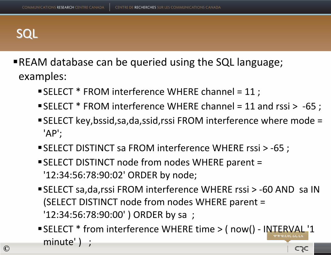
SQLSQL
�REAM database can be queried using the SQL language;
examples:
�SELECT * FROM interference WHERE channel = 11 ;
�SELECT * FROM interference WHERE channel = 11 and rssi > -65 ;
�SELECT key,bssid,sa,da,ssid,rssi FROM interference where mode =
'AP';
�SELECT DISTINCT sa FROM interference WHERE rssi > -65 ;
�SELECT DISTINCT node from nodes WHERE parent =
'12:34:56:78:90:02' ORDER by node;
�SELECT sa,da,rssi FROM interference WHERE rssi > -60 AND sa IN
(SELECT DISTINCT node from nodes WHERE parent =
'12:34:56:78:90:00' ) ORDER by sa ;
�SELECT * from interference WHERE time > ( now() - INTERVAL '1
minute' ) ;©

GUI GUI –– Spectrum Analyzer DataSpectrum Analyzer Data
©

GUI GUI –– Mapping CapabilitiesMapping Capabilities
©

Application Example: Investigation of the Outdoor Urban Interference environment by mining
The REAM data base….urban target area for the experiment
Google-View of the Test Site
In Ottawa, WiFi_CR units in Yellow
©

Application Example: Investigation of the Outdoor Urban Interference environment by
mining the REAM data base…experiment set up.
WiFi_CR Terminals
deployed, all in LOS of each
other
©

Interferers detected per 10 minute interval
With packet powers>-62 dBm, for all sniffers
Packet Occupancy, all interfering packets
With power >-82 dBm, as seen at each sniffer
Spectrum ‘Holes’
Application Example: Investigation of the Outdoor Urban Interference environment by
mining the REAM data base: Extracted Results…Occupancy by interference
©
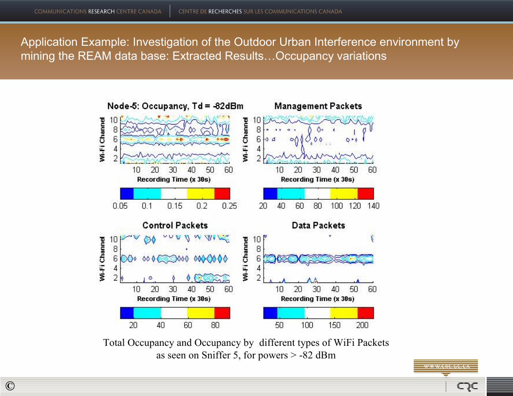
Total Occupancy and Occupancy by different types of WiFi Packets
as seen on Sniffer 5, for powers > -82 dBm
Application Example: Investigation of the Outdoor Urban Interference environment by
mining the REAM data base: Extracted Results…Occupancy variations
©

User activity per sniffer over a 10 minutes sample.
Users are unique source addresses; ~ same time,
But at different sniffers
CDF of user activity over a 10 minutes sample.
At different sniffers, power >-82 dBm
Application Example: Investigation of the Outdoor Urban Interference environment by
mining the REAM data base: Extracted Results…degrees of occupancy by users
©

Top Graph: RSSI of received beacons emanating from terminals 1-6,8
as measured on terminal 7
Bottom Graph: Correlation between beacons’ RSSI emanating from
terminal 6 and Terminals (1-7,8) as measured on Terminal 7
Top Graph: Correlation of beacons emanating from Terminal 1 as received
at Terminals pairs {7,7},{7,6},{7,2},{7,3}
Bottom Graph: Correlation of beacons emanating from Terminal 4 as received
at Terminals {7,7},{7,6},{7,2},{7,3}
60 Minute duration, distances between terminal pairs shown
Application Example: Investigation of the Outdoor Urban Interference environment by
mining the REAM data base: Extracted Results…correlation of interferenc
©

Dynamic Spectrum Access
� Objective: Implement an algorithm that chooses the WiFi channel providing the best throughput in a
long
range point to point WiFi link.
� Approach: This DSA algorithm is to be based on the per channel interference energy and occupancy.
3 Km
Interference from foreign WiFi
NLOS, vegetation blocked path
CRC with CR_NMSCSC Building with
Client Radio
©

Dynamic Spectrum Access
� DSA Process
1. CR NMS collects WiFi interference
data from Coral terminals
periodically
2. Collected data are stored in
database (REAM database)
3. Channel selection application selects
a best channel periodically according
to the WiFi interference
environment
4. Application sends switch channel
command to CR NMS when a better
channel is selected other than
current channel
5. CR NMS sends command to AP to
switch Channel
Coral API
REAM
WiFi Interference
Channel Selection Cognitive Engine
(1)
(2)
(3)(4)
(5)
CR_NM
S
©
Dynamic Spectrum Access
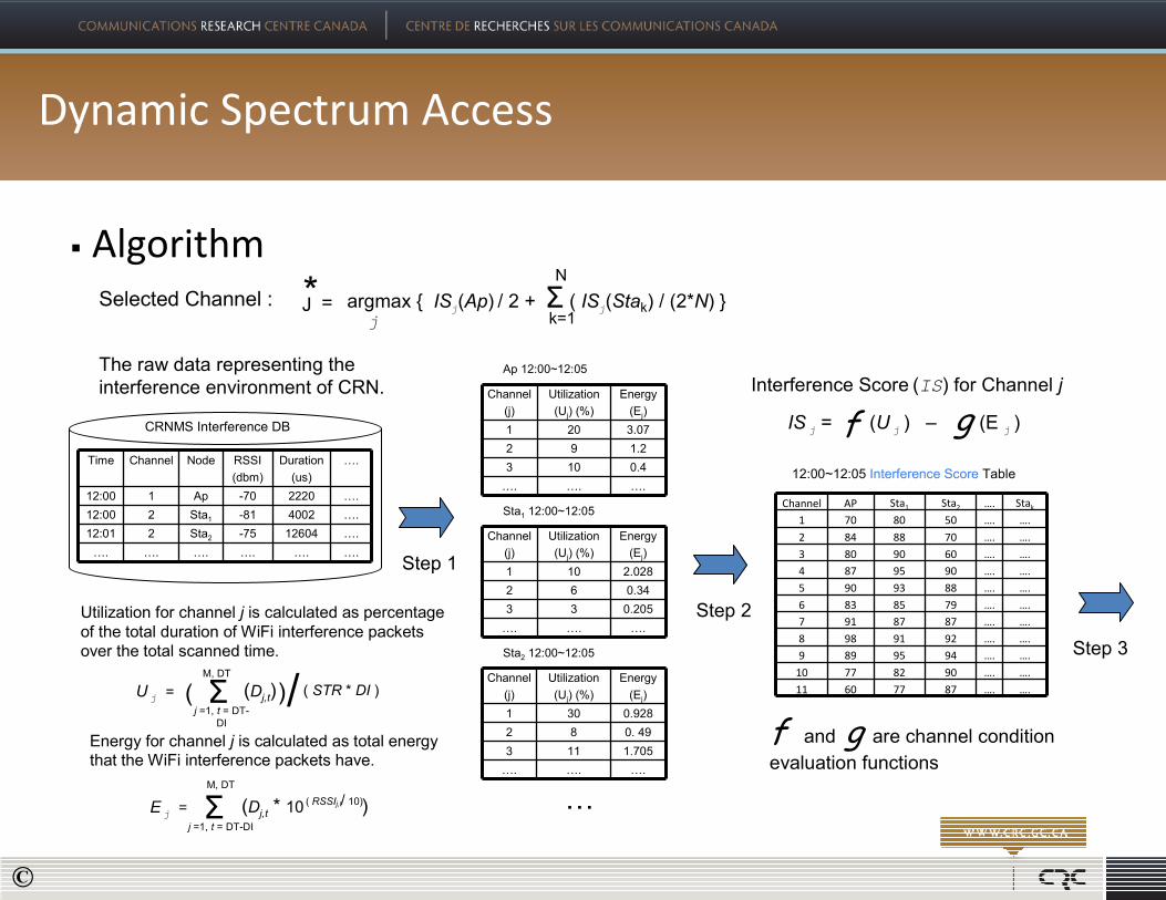
� Algorithm
CRNMS Interference DB
The raw data representing the
interference environment of CRN. Channel
(j)
Utilization
(Uj) (%)
Energy
(Ej)
1 20 3.07
2 9 1.2
3 10 0.4
…. …. ….
Ap 12:00~12:05
Channel
(j)
Utilization
(Uj) (%)
Energy
(Ej)
1 10 2.028
2 6 0.34
3 3 0.205
…. …. ….
Sta1 12:00~12:05
Channel
(j)
Utilization
(Uj) (%)
Energy
(Ej)
1 30 0.928
2 8 0. 49
3 11 1.705
…. …. ….
Sta2 12:00~12:05
Selected Channel : argmax { ISj(Ap) / 2 + Σ ( IS
j(Stak) / (2*N) }
k=1
N
j
=J*
Time Channel Node RSSI
(dbm)
Duration
(us)
….
12:00 1 Ap -70 2220 ….
12:00 2 Sta1 -81 4002 ….
12:01 2 Sta2 -75 12604 ….
…. …. …. …. …. ….
Uj= (Dj,t)Σ
j =1, t = DT-
DI
M, DT
( STR * DI )/( )
Utilization for channel j is calculated as percentage
of the total duration of WiFi interference packets
over the total scanned time.
Energy for channel j is calculated as total energy
that the WiFi interference packets have.
Σ (Dj,t * 10 )j =1, t = DT-DI
Ej=
M, DT
/( RSSIj,t 10)
g Interference Score (IS) for Channel j
12:00~12:05 Interference Score Table
….
….
….
….
….
….
….
….
….
….
….
….Channel AP Sta1 Sta2 Stak
1 70 80 50 ….
2 84 88 70 ….
3 80 90 60 ….
4 87 95 90 ….
5 90 93 88 ….
6 83 85 79 ….
7 91 87 87 ….
8 98 91 92 ….
9 89 95 94 ….
10 77 82 90 ….
11 60 77 87 ….
ISj= (U
j) – (E
j)f
Step 1
Step 2
Step 3
f and g are channel condition evaluation functions
…
©

Dynamic Spectrum Access
� Algorithm� The interference index is calculated as a weighted sum of each node’s IS. The AP takes half the
weight and each station shares equally for the other half
� The above weight scheme is designed for fairness. It can be changed for other special
requirements, such as QoS; In this case, each station may have different weight according to its
request for service
Step 3
Channel
( j )
Interference
Index
1 71
2 85
3 83
4 87
5 90
6 79
7 88
8 95
9 94
10 89
11 68
Interference Index12:00~12:05
Interference Index j = ISj(Ap) / 2 + Σ ( ISj(Stak) / (2*N) k=1
N
Selected Channel :k=1
N
j
=J* argmax { ISj(Ap) / 2 + Σ ( IS
j(Stak) / (2*N) }
©

Dynamic Spectrum Access
Channel Selection Algorithm Vs Random Channel Selection
Experiment was executed between CRC building 2and CSC building in August 11th, 2011
©

Future Work
� An improved multi-radio, multi-band WiFi_CR is in the
works.
� Cognitive Femtocells
� Sub-700 MHz WiFi_CR for TVWS applications.
� Increasing collaborations: the more, the merrier…putting
a practical spin on CR in the ISM environment.
� Moving into IEEE 802.11n; LTE, and beyond.
©

� Thank you….Questions?
©


![08. ism mabni [ism dhomir]](https://img.pdfslide.net/doc/110x75/55a4f0a71a28ab26408b480d/08-ism-mabni-ism-dhomir.jpg)