Embed Size (px)
Citation preview
國 立 交 通 大 學
電信工程學系
碩 士 論 文
感知網路之部份集中式動態頻譜擷取
Partial-Centralized Dynamic Spectrum Access
for Cognitive Radio Networks
研 究 生:鄭欣毅
指導教授:張仲儒 博士
中 華 民 國 九 十 八 年 七 月
感知網路之部份集中式動態頻譜擷取
Partial-Centralized Dynamic Spectrum Access for Cognitive
Radio Networks
研 究 生:鄭欣毅 Student:Shin-Yi Cheng
指導教授:張仲儒 博士 Advisor:Dr. Chung-Ju Chang
國 立 交 通 大 學
電信工程學系
碩 士 論 文
A Thesis Submitted to Department of Communication Engineering
College of Electrical and Computer Engineering National Chiao Tung University
in Partial Fulfillment of the Requirements for the Degree of Master of Science
in Communication Engineering
July 2009 Hsinchu, Taiwan
中華民國九十八年七月
i
感知網路之部份集中式動態頻譜擷取
研究生:鄭欣毅 指導教授:張仲儒 博士
國立交通大學電信工程學系碩士班
Mandarin Abstract
摘 要
隨著既有與新興無線通訊服務的增加,對於頻寬的需求量也日漸提高,然而
頻寬資源卻是有限的,對此問題大家已經開始尋求更有效的利用頻寬之方法。而
感知無線電(Cognitive Radio)被視為一個可以有效的使用頻寬的重要技術
在本篇論文中,我們提出了一個部份集中式的感知無線電動態頻譜擷取
(Partial- Centralized Cognitive Radio-Based Dynamic Spectrum Access)
機制來提供感知無線電系統之上鏈路資料傳送。此機制控制了包含主動式頻譜資
源偵測與上鏈路無線通訊資源分配。其主要目的是在固定頻段中提升傳輸量與頻
譜的效益。在提出的機制中,我們針對 WCDMA頻譜來做空閒頻譜偵測,根據這個
系統的特性,我們設計了主動式空閒頻譜偵測程序。此外,我們提供了一個上鏈
路無線通訊資源分配方法來有效的提升感知無線電系統的傳輸量。從模擬的結果
可以顯示出來我們所提出的方法,可以提升傳輸量,並增進頻譜使用效率。
ii
Partial-Centralized Dynamic Spectrum Access for
Cognitive Radio Networks
Student: Shin-Yi Cheng Advisor: Dr. Chung-Ju Chang
Department of Communication Engineering
National Chiao Tung University
English Abstract
Abstract
With the demand for additional bandwidth increasing due to existing and new
services, both spectrum policy and communication technologists are seeking solutions
for this apparent spectrum scarcity. The use of “cognitive radio” (CR) technology is
viewed as the key technology to fully utilize the bandwidth. In this thesis, a partial
centralized CR-based dynamic spectrum access (DSA) mechanism is proposed for CR
networks uplink transmission. The goals of PCCR-based DSA algorithm are
throughput maximization but without much more influence on WCDMA network. In
the proposed PCCR-based DSA mechanism, the proactive white space detection
provides the ability of CR users to execute the bandwidth request and adjust the
access power adaptively. The white space could be verified by this process with a
proactive manner. Then, the uplink resource management process provides the ability
of CR BS to manage the available resource and to perform the resource allocation
more efficiently.
iii
Acknowledgement
誌 謝
這篇論文的誕生,得感謝許多人所給予我的力量與幫助。首先我得感謝我的
指導教授張仲儒博士,在我撰寫此篇論文的過程中給予我不少的提點與指引;再
來則是得感謝早已自學校畢業的芳慶學長,犧牲自己的時間解答我所有的疑惑;
感謝文敬、志明、文祥、耀興、振宇學長不定時的幫助和建議,讓我能更快地進
入學術領域;感謝尚樺、宗利、英奇、巧瑩、維謙、邱胤、浩翔學長姐們,親切
的帶領我熟悉並融入這整個實驗室的大家庭;感謝一起走來的和儁、志遠、以及
盈伃,和我一起相互扶持走過這兩年,在我低潮的時候給予我繼續前進的勇氣;
感謝正忠、耀庭、蕊綺、心瀅以及玉棋,是你們讓實驗室變得更熱鬧,讓苦悶的
生活增添不少色彩。
最後,還得感謝我的父母、家人以及朋友,沒有你們的支持、關心和鼓勵,
我也無法順利而無憂的走過這兩年。
欣毅 謹誌
民國 九十八年八月
iv
Contents
UMandarin AbstractU ....................................................................................................... i
UEnglish AbstractU .......................................................................................................... ii
UAcknowledgementU ..................................................................................................... iii
UContentsU ....................................................................................................................... iv
UList of FiguresU ............................................................................................................. vi
UList of TablesU .............................................................................................................. vii
UChapter 1 IntroductionU ............................................................................................ 1
UChapter 2 System ModelU .......................................................................................... 7
UChapter 3 Partial-Centralized Cognitive Radio-Based Dynamic Spectrum
Access MechanismU ................................................................................ 10
U3.1U UProactive White Space DetectionU ............................................................ 12
U3.2U UUplink Resource Management ProcessU ................................................... 16
UChapter 4 Simulation Results and DiscussionU ...................................................... 21
U4.1U USimulation EnvironmentU .......................................................................... 21
U4.2U UPerformance EvaluationU .......................................................................... 24
U4.2.1U UThroughput of CR NetworkU ........................................................ 24
U4.2.2U UBlocking Probability of WCDMA NetworkU ................................ 27
v
U4.2.3U UAverage TX Power of WCDMA UsersU ....................................... 29
UChapter 5 ConclusionU ............................................................................................. 32
UAppendixU .................................................................................................................... 34
USpecification Adopted in the CR NetworkU ...................................................... 34
UList of SymbolsU ............................................................................................... 36
UBibliographyU ............................................................................................................... 38
UVitaU .............................................................................................................................. 40
vi
List of Figures UFig. 1.1: White Space conceptU ....................................................................................... 3
UFig. 2.1: The topology of system modelU ........................................................................ 8
UFig. 3.1: The Proactive White Space DetectionU ........................................................... 16
UFig. 4.1(a): The throughput of CR network (U ρ U=0.2)U ................................................. 25
UFig. 4.1(b): The throughput of CR network (U ρ U=0.5)U ................................................. 25
UFig. 4.1(c): The throughput of CR network (U ρ U=0.8)U ................................................. 26
UFig. 4.2(a): The Blocking Probability of WCDMA network (5 CR users)U ................. 27
UFig. 4.2(b): The Blocking Probability of WCDMA network (20 CR users)U ............... 28
UFig. 4.3(a): The Average TX power of WCDMA users (5 CR users)U ......................... 30
UFig. 4.3(b): The Average TX power of WCDMA network (20 CR users)U .................. 30
UFig. A.1: Description of a tile structureU ....................................................................... 34
UFig. A.2: Uplink frame structureU ................................................................................. 35
vii
List of Tables UTable 1.1: Possible Dimensions of the Spectrum SpaceU ............................................... 4
UTable 4.1: Simulation Parameters for WCDMA networkU ........................................... 22
UTable 4.2: Simulation Parameters for CR networkU ...................................................... 23
UTable A.1: List of SymabolsU ........................................................................................ 36
1
Chapter 1 Introduction
Recently, because of the increase in spectrum demand, the static spectrum
allocation policy that governmental agencies assign wireless spectrum to license
holders on a long-term basis for large geographical regions faces spectrum scarcity in
some particular spectrum bands. In contrast, a large portion of the assigned spectrum
is used sporadically. According to Federal Communication Commission (FCC) [1],
temporal and geographical variations in the utilization of the assigned spectrum range
from 15% to 85%. The inefficiency in the spectrum usage necessitates a new
communication paradigm to exploit the existing wireless spectrum opportunistically.
Dynamic spectrum access (DSA) is viewed as a novel approach to solve these current
spectrum inefficiency problems. The key enabling mechanism of dynamic spectrum
access technique is cognitive radio (CR).
The term, cognitive radio, can formally be defined as follow [2]: A “Cognitive
Radio” is a radio that can change its transmitter parameters based on interaction with
the environment which it operates. From this definition, we can define two main
characteristics of the cognitive radio [2]: cognitive capability and reconfigurability.
Cognitive capability refers to the ability of the radio technology to capture or sense
the information from its radio environment. This capability cannot simply be realized
by monitoring the power in some frequency band of interest but more sophisticated
2
techniques are required in order to capture the temporal and spatial variations in the
radio environment and avoid interference to other users. Through this capability, the
portions of the spectrum that are unused at a specific time or location can be identified.
Consequently, the best spectrum and appropriate operating parameters can be selected.
Reconfigurability refer to the ability of radio can be dynamically programmed
according to the radio environment. More specifically, the cognitive radio can be
programmed to transmit and receive on a variety of frequencies and to use different
transmission access technologies supported by its hardware design [3]. These two
characteristics of the CR enable the CR users to (I) determine which portions of the
spectrum is available and detect the presence of incumbents (primary users) (spectrum
sensing), (II) coordinate access to the channel with other CR users (secondary users)
(spectrum sharing), and (III) vacate the channel when incumbents are detected
(spectrum handoff).
The ultimate objective of the CR is to maximize the spectrum utilization through
exploiting the available resource efficiently but minimize the degradation of existing
systems. In earlier cognitive protocols, the CR network enables the usage of the
spectrum called “white space (spectrum hole)” that is temporally unoccupied by the
incumbents (primary user). A definition for spectrum hole: “A spectrum hole is a band
of frequencies assigned to a primary user, but, at a particular time and specific
geographic location, the band is not being utilized by that user,” is offered in [3]. In
Fig. 1.1, it shows that in time domain and frequency domain, there will be some white
space unused by the primary network. Since the primary network has an exclusive
right to the spectrum band, the CR network should minimize the interference to the
primary network. If the frequency band is further used by primary network, the CR
network should switch to another white space. Thus, how to dynamically and
3
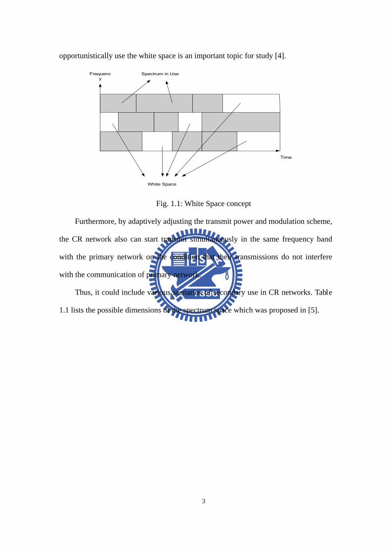
opportunistically use the white space is an important topic for study [4].
Time
Frequency
Spectrum in Use
White Space
Fig. 1.1: White Space concept
Furthermore, by adaptively adjusting the transmit power and modulation scheme,
the CR network also can start transmit simultaneously in the same frequency band
with the primary network on the condition that their transmissions do not interfere
with the communication of primary network.
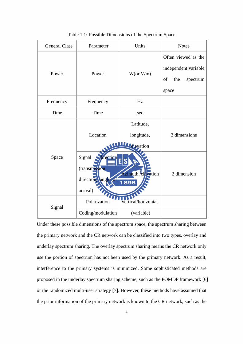
Thus, it could include various scenarios of secondary use in CR networks. Table
1.1 lists the possible dimensions of the spectrum space which was proposed in [5].
4
Table 1.1: Possible Dimensions of the Spectrum Space
Under these possible dimensions of the spectrum space, the spectrum sharing between
the primary network and the CR network can be classified into two types, overlay and
underlay spectrum sharing. The overlay spectrum sharing means the CR network only
use the portion of spectrum has not been used by the primary network. As a result,
interference to the primary systems is minimized. Some sophisticated methods are
proposed in the underlay spectrum sharing scheme, such as the POMDP framework [6]
or the randomized multi-user strategy [7]. However, these methods have assumed that
the prior information of the primary network is known to the CR network, such as the
General Class Parameter Units Notes
Power
Power
W(or V/m)
Often viewed as the
independent variable
of the spectrum
space
Frequency Frequency Hz
Time Time sec
Space
Location
Latitude,
longitude,
elevation
3 dimensions
Signal direction
(transmission
direction, angle of
arrival)
Azimuth, elevation
2 dimension
Signal Polarization Vertical/horizontal
Coding/modulation (variable)
5
state transition probability of the primary users, which is impractical.
The underlay spectrum sharing scheme is that the CR network begins
transmission such that the transmit power is regarded as noise by the primary network.
For the underlay spectrum sharing, the interference temperature is to quantify and to
manage the interference, which is proposed by FCC Spectrum Policy Task Force [8].
It is defined as the RF power measured at a receiving antenna per unit bandwidth and
indicates the tolerable interference level in the licensed user’s receiver. To formulate
the interference temperature model, it needs take some information about the RF
environment, the primary network, and the CR network architecture into
consideration. In [9], two interference temperature models are proposed, one is ideal
interference temperature model which is receiver-based and different receivers have
their own interference threshold. The other one is generalized interference model
which is measured in some measure point but with less prior information. And, in [10],
the author both considers these two interference models to design an OFDMA-based
spectrum sharing scheme.
In this thesis, we assume that in order to increase the utilization of WCDMA
spectrum band, we let WiMAX-OFDMA network to dynamically access this band.
Thus, the WiMAX-OFDMA network is CR network and the infrastructure-based
WCDMA network is primary network in our scenario. In this band the secondary
access of CR network appears as wideband noise due to the nature of spread spectrum
technique of WCDMA network. Our challenge is how to protect the WCDMA user’s
right under bit error rate constraints which is tolerable for some kind of application or
service and we can open some spectrum opportunities for the CR network to use.
Thus, we design a partial-centralized CR-based DSA mechanism for CR network to
execute uplink transmission in the WCDMA spectrum band. This thesis discusses the
6
system’s model, proposed mechanism, the performance of total throughput, and the
degradation of WCDMA network.
The remaining part of the thesis is as follows. Chapter 2 describes the system
environment and the network topology, including primary network and CR network.
Then, chapter 3 describes the partial-centralized CR-based DSA mechanism. In
chapter 4, simulation results are presented and discussed. Then, concluding remarks is
given in chapter 5. Moreover, the final section is the Appendix.
7
Chapter 2 System Model
The components of the whole network architecture can be classified in two
groups as the primary network and the CR network.
Primary network is an existing network infrastructure has an exclusive right to a
certain spectrum band. In this thesis, we consider the infrastructure-based WCDMA
cellular network as the primary network which is operated in licensed band. The
WCDMA cellular network is operating around 2.0 GHz with a pair of 5 MHz
spectrum bands to execute its uplink and downlink transmission. The basic idea of
WCDMA network is using the code division multiple access (CDMA) technique to
against the interference and allow signals of multiple users in same spectrum. Due to
the nature of the CDMA technique, the WCDMA cell capacity depends on the
maximal tolerable interference level of each WCDMA user. To protect the WCDMA
users’ link qualities, the WCDMA BS needs control the number of the interference
WCDMA users in the cell and execute the power control mechanisms.
CR network, also named secondary network, is allowed to access a desired
spectrum only in an opportunistic manner. In this thesis, we consider the
infrastructure-based WiMAX-OFDMA [12] as CR network. Therefore, the
components of a CR network are CR user and CR base station. Orthogonal frequency
division multiplexing access (OFDMA) has been adopted for WiMAX network which
8
is proposed as a promising technique for future multimedia wireless communication
systems due to its ability to mitigate frequency selective fading, intersymbol
interference (ISI), and its flexibility for adaptive modulation on each subcarrier. Thus,
WiMAX-OFDMA network can support data rate in the range of 32-130 Mbps
depending on the bandwidth of operation as well as the modulation and the coding
scheme. The basic allocation unit in frequency domain for the WiMAX-OFDMA
network is a subchannel which is composed of a set of subcarriers. According to the
channel quality, different modulation schemes such as QPSK, 16-QAM, and 64-QAM
can be used.
WCDMA cell
WCDMA BS
WCDMA user
WCDMA cell
WCDMA BS
WCDMA user
CR user
WCDMA cell
WCDMA BS
WCDMA user
CR cell
CR BS
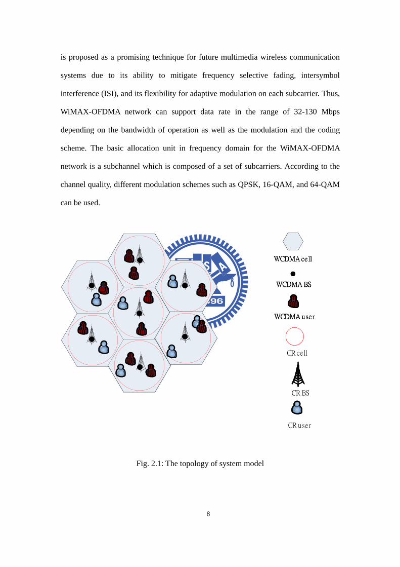
Fig. 2.1: The topology of system model
9
Fig. 2.1 shows the topology of system model, which consists of two types of
networks: a primary network and a CR network. Here, we assume that the CR BSs are
collocated with WCDMA BSs to measure the same uplink interference level, and
therefore they have the same service coverage. We select the uplink spectrum band of
WCDMA network as the CR operating spectrum. Thus, we only consider the uplink
transmission of CR users to share the same spectrum with WCDMA users, while the
downlink transmission of CR BS still adopts a licensed band. Because it’s difficult for
CR network to guarantee available resource, we assume that only BE traffics [14] are
supported for CR users to access the uplink WCDMA spectrum band by adopting
partial-centralized CR-based DSA mechanism. Otherwise, we also assumed that
WCDMA network and CR network use single omni-directional antennas. The other
detailed specification adopted in the CR network will be described in the Appendix.
10
Chapter 3 Partial-Centralized Cognitive Radio-Based Dynamic Spectrum Access Mechanism
To efficiently use of the available resource in WCDMA frequency band and to
guarantee the received signal quality of WCDMA users, we propose a
partial-centralized cognitive radio-based dynamic access (PCCR-based DSA)
mechanism for the CR network to temporarily use the frequency spectrum.
In WCDMA network, WCDMA user needs control the received power strength
over the interference from others is larger than the target SINR value, denoted by
oSINR , to maintain the received signal quality. If the current interference level is too
high to maintain the target SINR value, the WCDMA BS need to start blocking the
new coming user to decrease the overall interference level in WCDMA network and
maintain performance. According to this concept, the maximum tolerable interference
level, denoted by maxI , can be calculated. The maxI is that a WCDMA user can
endure for a target SINR requirement when transmitting with maximum transmission
power maxP at cell edge [11]. It can be precisely expressed by,
11
max maxmax
o
G L PISINR⋅ ⋅
=,
(3.1)
where G is the processing gain, oSINR is the SINR requirement of a specific
service type, and maxL is the maximum path loss from cell edge to BS. According to
maxI , a PCCR-based DSA mechanism is designed to model the behavior of CR
network to interact with the WCDMA network without much influence.
In the design of PCCR-based DSA mechanism, the CR BS measures the power
spectrum density of average interference and noise level, denoted by NI , from the
WCDMA users over the past U CR frame time. Then, the CR BS calculates the
admissible received power, denoted as CRP , as the upper bound of total received
power from CR users at the CR BS. To protect the access right of WCDMA users,
CRP is given by,
( ) ( ){ }maxmax 1 ,0 ; [0,1]CR wP I NI Bα α= − ⋅ − ⋅ ∈ , (3.2)
where α is a safety factor to protect WCDMA network and wB is the overall
system bandwidth. The larger the value α is, the more protection the CR network
provides. These information about NI , and α will be broadcasted through the
licensed band of CR network. Moreover, CR users can also calculate CRP according
to the downlink broadcast signal.
The partial-centralized CR-based DSA mechanism contains two parts, the
proactive white space detection and the uplink resource management process. These
two processes are individually executed in CR user side and CR BS side. When a CR
user has data to be transmitted, it has to perform the proactive white space detection.
The proactive white space detection provides the ability of CR users to execute the
bandwidth request, to adjust the access power adaptively, and to detect the white
12
space. After receiving the request from CR users, the CR BS performs the uplink
resource management process. The uplink resource management process provides the
ability of CR BS to manage the available resource and to perform the resource
allocation more efficiently.
3.1 Proactive White Space Detection
Based on WiMAX-OFDMA protocol, CR user transmits a randomly chosen
bandwidth request ranging code to the CR BS to notify its bandwidth request try when
a packet arrivals. Then, the CR BS detects a bandwidth ranging code, and replies a
CDMA allocation information element which indicates the uplink resources for the
CR user who transmits the detected bandwidth ranging code to transmit bandwidth
request header. To let the received SINR at CR BS remains at a target values, the
transmission of CR users are power-controlled to compensate the interference from
WCDMA users. Therefore, CR users can detect accessible white space in the
WCDMA frequency band. The white space is identified by both CR BS and CR user
in a proactive manner through bandwidth request process. The detailed procedure of
proactive white space detection is described as the following phases.
Phase 1: Calculate the initial access power
A CR user first acquires NI , α , and estimates the signal loss, denoted by lL ,
through downlink broadcast signal from CR BS. Then, the CR user calculates the
open-loop TX power of bandwidth request ranging code, denoted as oP . The oP is a
initial power value to compensate the effects of NI and signal loss, it can be
precisely expressed by,
BRrc ro
l
SINR NI BPL⋅ ⋅
= ,
(3.3)
where BRrcSINR is the required SINR value [13] of bandwidth request ranging code
13
to achieve target detection probability, rB is the bandwidth of ranging subchannels.
Phase 2: Feasibility checking
Then, the CR user checks whether the current transmission of ranging code is
feasible or not, denoted as the following condition,
max _ _( ) ( )o TX r o l CR MAP rP P P and P L P P≤ − ⋅ ≤ − , (3.4)
where _TX rP is the transmit power of the CR user in the ranging slot time, and
_MAP rP is the total allocated received power in the ranging slot time, they can be
derived from the allocation results in UL-MAP. Moreover, the left hand of eq. (3.4) is
the transmit power constraint of CR user, and the right hand is the received power
constraint at the CR BS.
If the condition is satisfied, it means the CR user identifies the current RF
environment as an opportunity and starts to transmit bandwidth request ranging code.
If the condition is not satisfied, the CR user should execute the back-off procedure.
The back-off procedure here means the CR user selects a back-off number w
randomly between zero and W , and the number w means the number
of frames the CR user shall defer. Then, return to phase 1.
Phase 3: Transmit BR header
After transmitting the bandwidth request ranging code, the CR user should wait
for pN frame time, where pN is the response delay, we assumed it is fixed for
simplicity. Once the CR BS receives the ranging code successfully, it will allocate an
uplink transmission slot for bandwidth request header to this CR user and informs the
CR user through the CDMA_allocation_IE [12]. However, if the detected requests are
too many to allocate, the CR BS should reject some of these requests.
Thus, if the CR user receives the corresponding allocation information, it means
14
the bandwidth request ranging code is detected. Then, the CR user transmits a
bandwidth request header with power BRP . The BRP is calculated according to oP , it
is expressed by,
d BRBR o
r BRrc
B SINRP PB SINR
= ⋅ ⋅ , (3.5)
where BRSINR is the required SINR value of bandwidth request header to achieve
target detection probability, dB is the bandwidth of a data subchannel. In the
bandwidth request header, the CR user will record not only the increment buffered
bits but also BRP . Thus, the CR BS can decide the transmission capability of this CR
user through BRP and maxP .
If the allocation information is not received, it has two possible situations. One is
the bandwidth request ranging code sent by the CR user is not detected due to the
interference. The other one is that although the bandwidth request ranging code is
detected, the current interference and noise level is too high to allocate for the
bandwidth request header under the received power constraint. Thus, the CR user
should execute the back-off procedure and ramps up the transmission power of
ranging code to increase the detection probability. The back-off procedure is the same
as that we have mentioned before. After the back-off procedure, the CR user acquires
new downlink information. Then, CR user ramps up oP with the offset value offsetP ,
and adjusts it according to NI and the interference and noise level of previous cycle,
denoted as 'NI , it is expressed by,
'o o offsetNIP P PNI
= ⋅ ⋅ ,
(3.6)
Then, go to phase 2 to check its feasibility.
Phase 4: Last acknowledgement
After transmitting the bandwidth request header, the CR user also should wait for
15
pN frame time. Then, the CR user checks whether receiving the acknowledge from
the CR BS. Besides, a fine-tuning value of BRP is recorded in acknowledge to let the
CR user can synchronize transmit power with the CR BS.
If the acknowledge is received, it means the CR user is successful to inform the
CR BS of its resource demand. In addition, it also means the current radio
environment can be considered as a “white space” for the CR user. If this
acknowledge is not received, it means the bandwidth request header transmitting by
the CR user is not detected. Thus, the CR user executes the same back-off procedure
and power compensation as in phase 3. Then, return to phase 2.
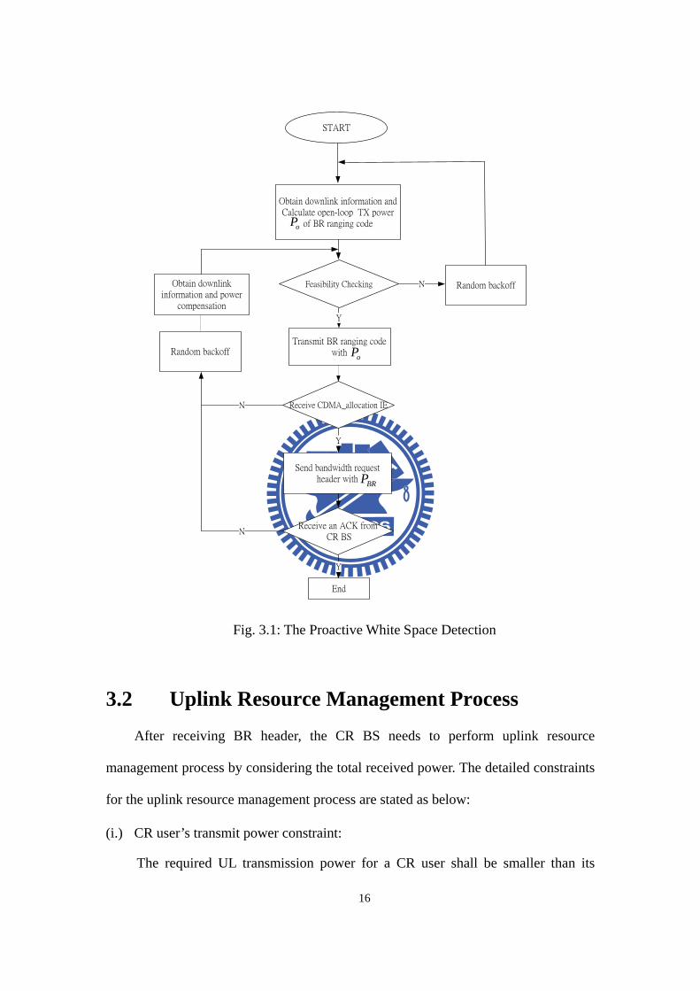
The flow chart of proactive white space detection is shown in Fig. 3.1.
16
START
Obtain downlink information and Calculate open-loop TX power
of BR ranging code
Feasibility Checking N
Y
Receive CDMA_allocation IE
Y
Send bandwidth request header with
Receive an ACK from CR BS
Y
End
Random backoff
Transmit BR ranging code with
N
N
Obtain downlink information and power
compensation
oP
oP
BRP
Random backoff
Fig. 3.1: The Proactive White Space Detection
3.2 Uplink Resource Management Process
After receiving BR header, the CR BS needs to perform uplink resource
management process by considering the total received power. The detailed constraints
for the uplink resource management process are stated as below:
(i.) CR user’s transmit power constraint:
The required UL transmission power for a CR user shall be smaller than its
17
maximum transmission power. Here, we assume that all CR users have same
maximal transmission power as WCDMA users.
(ii.) Received power constraint
The total UL received power from CR users shall be smaller than CRP .
(iii.) Slot allocation constraint:
Each slot of every subchannel can only be allocated to one CR user, which is a
basic constraint for the single-antenna system of one cell.
Under these constraints, the uplink resource management process is designed to
maximize the profits of CR network. The profits here means maximal throughput
under the received power constraint. Furthermore, the CR users’ traffic we consider
in this thesis is BE. The BE is designed to support data streams which have no QoS
requirement. In this process, the CR BS will allocate the UL resource for BR
headers first, then the resource left will be allocated for BE. In chapter II, we have
made an assumption that the channel response is flat and only concerns about the
effect of long-term fading. Therefore, we only need to consider the multi-user
diversity according to their transmission capability when we design this process.
The uplink resource management process will be implemented as the following
phases:
Phase 1:
The number of slots for bandwidth request headers, denoted by H , can be
derived according to the number of detected requests, denoted by reqN , and the
limitation of received power, it is expressed by,
( )min , ,CRreq d
h
PH M N N Mδ
= ⋅ ⋅
, (3.7)
hδ is the required received power of bandwidth request header to achieve target
18
detection probability, which can be precisely expressed by,
h BR dSINR NI Bδ = ⋅ ⋅ , (3.8) where M is the number of slots per frame, and dN is the number of data
subchannels. If the available slots for bandwidth request headers H is smaller than
reqN , it means the current available resource is not enough to allocate all requests.
Thus, the CR BS should randomly select H requests from reqN requests to allocate
resource for them.
Phase 2: Pre-allocation
In order to maximize the throughput of CR network, we first find a combination
of residual data subchannels, denoted as *y , to achieve the target. The *y is
composed of three items *1y , *
2y and *3y , where jy means the number of data
subchannels allocated for modulation order j . Such combination can be found as
optimization equation given by,
Objective:
1 2 3
3*
[ , , ] 1arg max 2 jy y y j
j y=
=
= ⋅ ⋅∑yy (3.9)
Subject to the system constraints:
(i) Subchannel constraint: 3
1j d
j
Hy NM=
≤ − ∑
(ii) Received power constraint:
3
1, 0 CR
j j CR h jj j
PHy P yM
δ δδ=
⋅ ≤ − ⋅ ≤ ≤ ∑
, where jδ is the minimum received power on a subchannel under the required BER
with modulation order j , it is given by [15]:
19
21, QPSK
(2 1) ln(5 ) 2, 16-QAM 1.5
3, 64-QAM
jd
jBER NI B jδ
⋅ − − ⋅ ⋅ ⋅ ⋅ = =
. (3.10)
If the optimization equation finds more than one combinations, the CR BS will select
the combination with the minimum total received power. And, in the design of the
resource allocation, the allocation of each modulation order cannot beyond the
number of subchannels we have obtained. Note that the subchhanels of a high
modulation order can also be allocated to a low order modulation because it doesn't
violate the received power constraint.
Phase 3: Allocate for BE traffics
We start to allocate the resource for BE traffics. We select the CR users
according to their link quality, so the CR user with the better link quality will be
selected first and allocated resource prior to the others. The allocation for BE traffic is
described as below.
First, select a CR user with the best link quality, and check its transmission
capability. The transmission capability could be verify by BRP , i.e. find the highest
modulation order j to let max 'j
BRBR
SINR NIP PSINR NI
≥ ⋅ ⋅ . Then, allocate its data with the
modulation order j . However, if the resource belongs to modulation order j is
exhausted, the CR BS decreases one modulation order of the CR user until the
resource is available. After allocated the data for BE of the CR user under the transmit
power constraint, the resource belong to each modulation order will be updated. This
phase is repeated until all BE traffics have been allocated or all resource are exhaust.
Phase 4: End
The uplink resource allocation is done, and the CR BS broadcasts the allocation
results in UL-MAP. According to UL-MAP, the CR user can decide the transmit
20
power under the current NI and lL .The transmit power on a subchannel is offset by
BRP , NI , and 'lL of the previous successful cycle of proactive white space detection
and the required SINR value for modulation j ,denoted by jSINR , i.e.
'
'j l
BRBR l
SINR LNIPSINR NI L⋅ ⋅ ⋅ . Note that the total transmission power is bounded by maxP .
21
Chapter 4 Simulation Results and Discussion
4.1 Simulation Environment
In the simulation, we only consider the large scale fading for the wireless fading
channels. The large scale fading comes from the signal strength degradation over
distance and shadowing effect. The path loss is modeled as 128.1 + 37.6log R (dB)
[16], where R is the distance between the BS and SS in unit of kilometers. Besides,
the shadowing model is assumed log-normal distributed with zero mean and standard
deviation of 8 dB.
For the WCDMA network, we only consider the voice call users in the cells and
the FDD mode is adopted. Fast Closed loop power control in frequency of 1500 Hz
with step size 1, 2, or 3 dB. Furthermore, the conditions that WCDMA BS blocks a
new arrival WCDMA user is that if a WCDMA user in cell cannot ramp up its
transmission power anymore to against the interference or the new arrival WCDMA
user cannot overcome the interference. The values of simulation parameters for
WCDMA network list in Table 4.1.
22
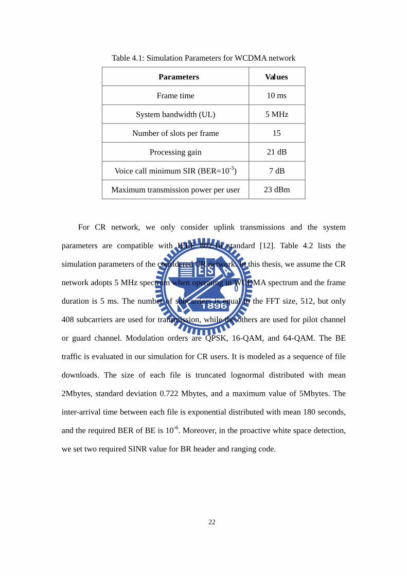
Table 4.1: Simulation Parameters for WCDMA network
Parameters Values
Frame time 10 ms
System bandwidth (UL) 5 MHz
Number of slots per frame 15
Processing gain 21 dB
Voice call minimum SIR (BER=10-3) 7 dB
Maximum transmission power per user 23 dBm
For CR network, we only consider uplink transmissions and the system
parameters are compatible with IEEE 802.16 standard [12]. Table 4.2 lists the
simulation parameters of the considered CR network. In this thesis, we assume the CR
network adopts 5 MHz spectrum when operating in WCDMA spectrum and the frame
duration is 5 ms. The number of subcarriers is equal to the FFT size, 512, but only
408 subcarriers are used for transmission, while the others are used for pilot channel
or guard channel. Modulation orders are QPSK, 16-QAM, and 64-QAM. The BE
traffic is evaluated in our simulation for CR users. It is modeled as a sequence of file
downloads. The size of each file is truncated lognormal distributed with mean
2Mbytes, standard deviation 0.722 Mbytes, and a maximum value of 5Mbytes. The
inter-arrival time between each file is exponential distributed with mean 180 seconds,
and the required BER of BE is 10-6. Moreover, in the proactive white space detection,
we set two required SINR value for BR header and ranging code.
23
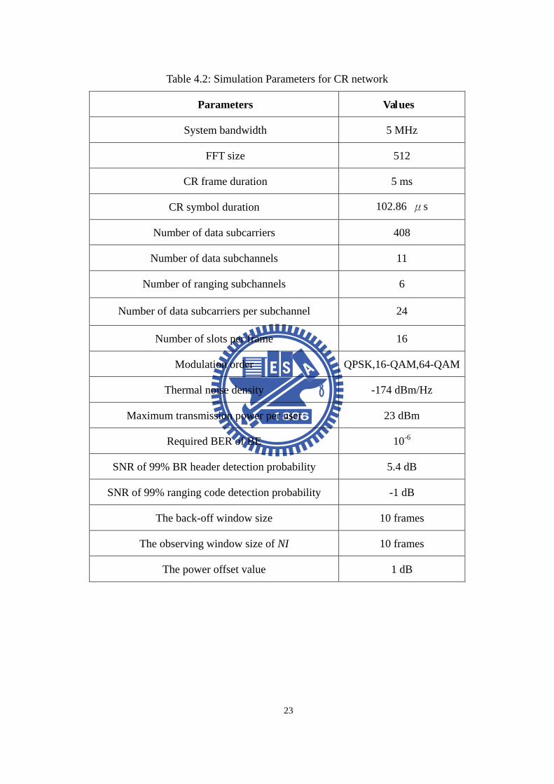
Table 4.2: Simulation Parameters for CR network
Parameters Values
System bandwidth 5 MHz
FFT size 512
CR frame duration 5 ms
CR symbol duration 102.86 μs
Number of data subcarriers 408
Number of data subchannels 11
Number of ranging subchannels 6
Number of data subcarriers per subchannel 24
Number of slots per frame 16
Modulation order QPSK,16-QAM,64-QAM
Thermal noise density -174 dBm/Hz
Maximum transmission power per user 23 dBm
Required BER of BE 10-6
SNR of 99% BR header detection probability 5.4 dB
SNR of 99% ranging code detection probability -1 dB
The back-off window size 10 frames
The observing window size of NI 10 frames
The power offset value 1 dB
24
4.2 Performance Evaluation We simulate seven WCDMA cells case where one CR BS is collocated with the
central WCDMA cell BS. CR users can access WCDMA UL spectrum by adopting
the PCCR-based DSA mechanism. We define the load intensity of WCDMA network
as the ratio of the traffic intensity, denoted by ρ , to achieve the 5% blocking
probability. In the simulation, the number of CR users varies from 5 to 20, and each of
them contains BE traffic with the arrival rate 88.9 Kbps. Moreover, the safety factor
α varies from 0.9 to 0.6. Besides, we show the result with or without the
pre-allocation (PA) procedure in the uplink resource management process. The uplink
resource management process without PA procedure could be implemented as that.
The allocation for each BE traffic will check all allocation constraint we have
mentioned before, and then allocate with the highest achievable modulation order.
The following performance metric will be measured: (i) throughput of CR
network, (ii) blocking probability of WCDMA network, and (iii) average transmission
power of WCDMA user.
4.2.1. Throughput of CR Network
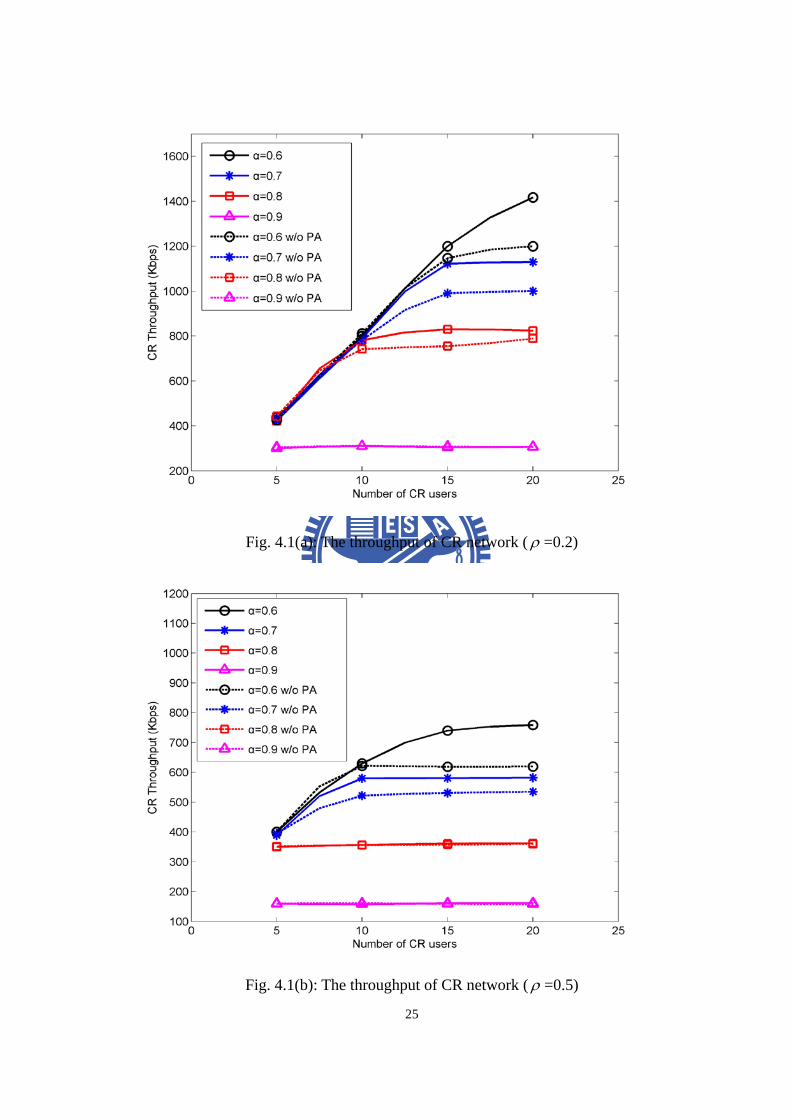
Figure 4.1(a)-(c) shows the throughput of CR network versus the number of CR
users and the load intensity of WCDMA network. These figures also show the
simulation results with different safety factor and the improvement of PA procedure..
25
Fig. 4.1(a): The throughput of CR network ( ρ =0.2)
Fig. 4.1(b): The throughput of CR network ( ρ =0.5)
26
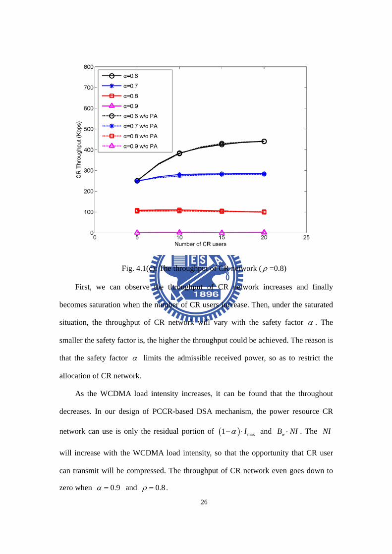
Fig. 4.1(c): The throughput of CR network ( ρ =0.8)
First, we can observe the throughput of CR network increases and finally
becomes saturation when the number of CR users increase. Then, under the saturated
situation, the throughput of CR network will vary with the safety factor α . The
smaller the safety factor is, the higher the throughput could be achieved. The reason is
that the safety factor α limits the admissible received power, so as to restrict the
allocation of CR network.
As the WCDMA load intensity increases, it can be found that the throughout
decreases. In our design of PCCR-based DSA mechanism, the power resource CR
network can use is only the residual portion of ( ) max1 Iα− ⋅ and wB NI⋅ . The NI
will increase with the WCDMA load intensity, so that the opportunity that CR user
can transmit will be compressed. The throughput of CR network even goes down to
zero when 0.9α = and 0.8ρ = .
27
In addition, the throughput of CR network with PA procedure is higher than that
without PA procedure when the safety factor or the load intensity of WCDMA
network is small enough. The reason is that when the safety factor α or the load
intensity of WCDMA network is small enough, the higher modulation orders could be
supported under the received power constraint. Thus, to user the PA procedure, it
could find a best combination to efficiently use the power resource.
4.2.2. Blocking Probability of WCDMA Network
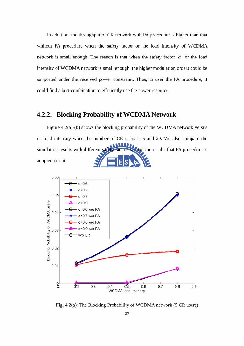
Figure 4.2(a)-(b) shows the blocking probability of the WCDMA network versus
its load intensity when the number of CR users is 5 and 20. We also compare the
simulation results with different safety factor α and the results that PA procedure is
adopted or not.
Fig. 4.2(a): The Blocking Probability of WCDMA network (5 CR users)
28
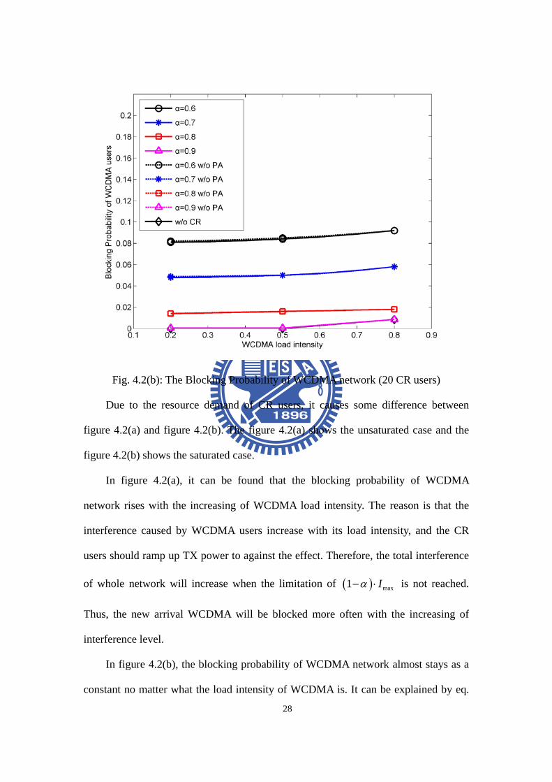
Fig. 4.2(b): The Blocking Probability of WCDMA network (20 CR users)
Due to the resource demand of CR users, it causes some difference between
figure 4.2(a) and figure 4.2(b). The figure 4.2(a) shows the unsaturated case and the
figure 4.2(b) shows the saturated case.
In figure 4.2(a), it can be found that the blocking probability of WCDMA
network rises with the increasing of WCDMA load intensity. The reason is that the
interference caused by WCDMA users increase with its load intensity, and the CR
users should ramp up TX power to against the effect. Therefore, the total interference
of whole network will increase when the limitation of ( ) max1 Iα− ⋅ is not reached.
Thus, the new arrival WCDMA will be blocked more often with the increasing of
interference level.
In figure 4.2(b), the blocking probability of WCDMA network almost stays as a
constant no matter what the load intensity of WCDMA is. It can be explained by eq.
29
(3.2), the admissible received power CRP is the residual portion of wB NI⋅ and
( ) max1 Iα− ⋅ . In the long-term basis, the total interference is fixed around ( ) max1 Iα− ⋅ ,
so as to let the blocking probability stay as a constant. Besides, when 0.9α = and
0.8ρ = , the blocking probability only reflects the situation of that without CR
network scenario.
Finally, we can find that whether the PA procedure is adopted or not, it almost
makes no difference to the blocking probability. It is because the PA procedure only
makes use of the power resource more efficiently under the received power constraint.
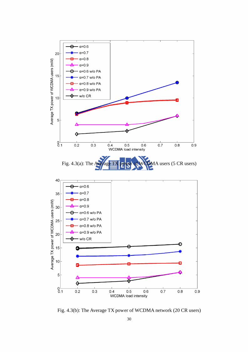
4.2.3. Average TX Power of WCDMA Users
Next, figure 4.3(a)-(b) shows the average TX power of the WCDMA users
versus the load intensity when the number of CR users is 5 and 20. We also compare
the simulation results with different safety factor α and the results that PA
procedure is adopted or not. Again, the figure 4.3(a) shows the unsaturated case and
the figure 4.3(b) shows the saturated case.
30
Fig. 4.3(a): The Average TX power of WCDMA users (5 CR users)
Fig. 4.3(b): The Average TX power of WCDMA network (20 CR users)
31
First, we could be found the trend of figure 4.3(a)-(b) are similar to figure
4.2(a)-(b). In figure 4.3(a), due to the increasing of the total interference from
WCDMA users and CR users. In order to compensate the increasing of interference,
each WCDMA user should ramp up its TX power, so that the average TX power will
also increase with the load intensity of WCDMA network. In figure 4.3(b), due to the
fixed total interference level by eq. (3.2), each WCDMA user needs against that with
the fixed TX power. Otherwise, the average TX power varies with the safety factor
α . The average TX power is inverse proportional to the safety factor. Finally, the
curves with 0.9α = shows the phenomenon that current WCDMA spectrum is only
used by WCDMA users when load intensity is 0.8 because the current interference
from WCDMA users is too high to start the transmission of CR network. Finally, we
can find that the PA procedure also doesn’t affect the average TX power. The reason
we have mentioned before.
32
Chapter 5 Conclusion
The limited available spectrum and the inefficiency in the spectrum usage
necessitate a new communication paradigm to exploit the existing wireless spectrum
opportunistically. In addition, with the demand for additional bandwidth increasing
due to existing and new services, both spectrum policy and communication
technologists are seeking solutions for this apparent spectrum scarcity. In this thesis, a
PCCR-based dynamic spectrum access mechanism is proposed for CR network uplink
transmission. The goals of PCCR-based DSA mechanism are throughput
maximization without much more influence on WCDMA network. In the proposed
PCCR-based DSA mechanism, the proactive white space detection provides the
ability of CR users to execute the bandwidth request, and adjust the access power
adaptively. And, the white space could be verified by this process with a proactive
manner. Then, the uplink resource management process provides is to let the CR BS
to manage the available resource and to perform the resource allocation more
efficiently.
In the simulation results and discussion, the PCCR-based DSA mechanism is
presented for CR network to operate in WCDMA spectrum. From the simulation
results, we can conclude that the PCCR-based DSA mechanism can obtain additional
throughput from the power resource of WCDMA network while the degradation is in
33
a reasonable range, such as α is 0.7. Besides, the pre-allocation in uplink
management process can achieve higher system throughput under the received power
constraint. Thus, the goal to improve the spectrum efficiency could be realized.
34
Appendix
Specification Adopted in the CR Network In [3], OFDM was proposed as a better modulation strategy for cognitive radio
by virtue of its flexibility and computational efficiency. For its operation, OFDM uses
a set of carrier frequencies centered on a corresponding set of narrow channel
bandwidths. Most important, the availability of rate feedback through a feedback
channel permits the use of bit-loading, whereby the number of bits/symbol for each
channel is optimized for the SNR characterizing that channel. Therefore, many
existing CR network architectures are OFDM-based [4].
In this thesis, a set of subcarriers within WCDMA frequency band is grouped
into an OFDM subchannel. There are several ways for grouping subcarriers into a
subchannel, and we assume the partial usage of subchannels (PUSC) permutation is
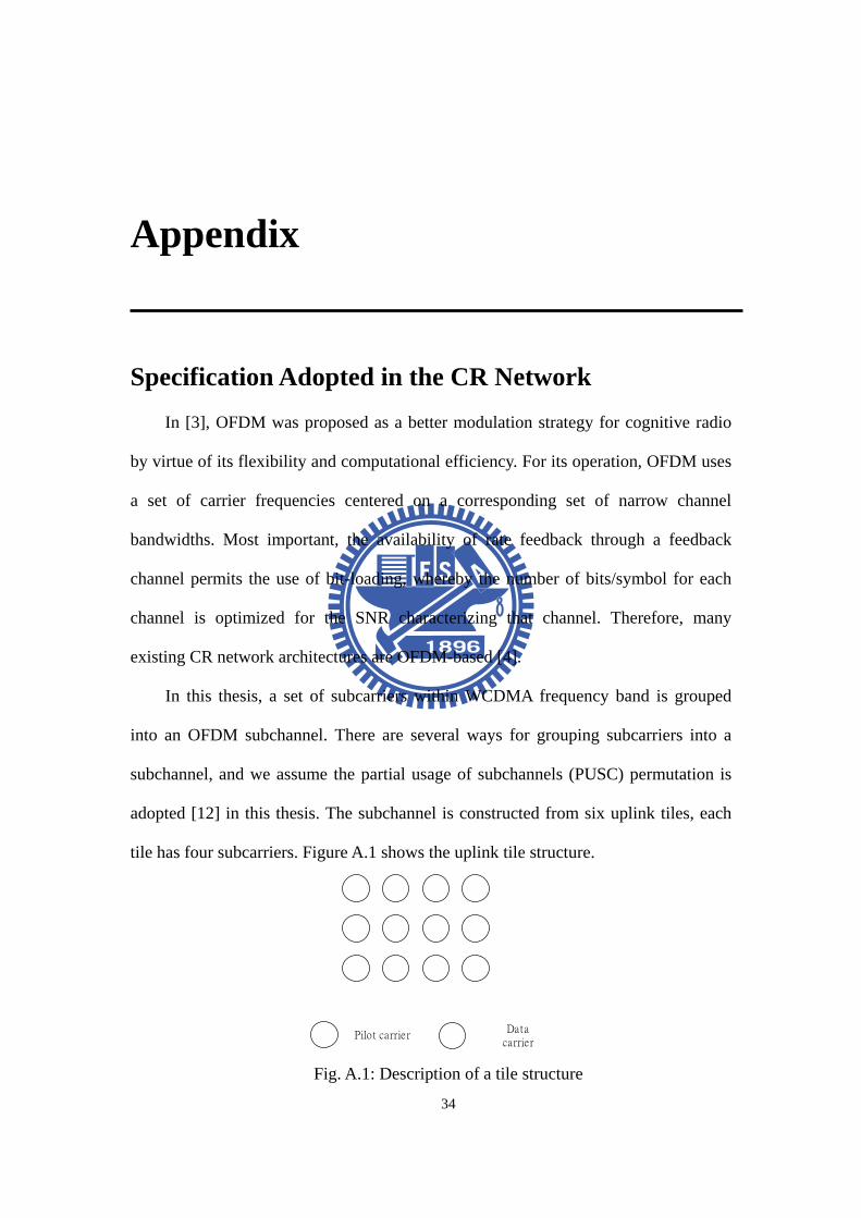
adopted [12] in this thesis. The subchannel is constructed from six uplink tiles, each
tile has four subcarriers. Figure A.1 shows the uplink tile structure.
Pilot carrierData
carrier Fig. A.1: Description of a tile structure
35
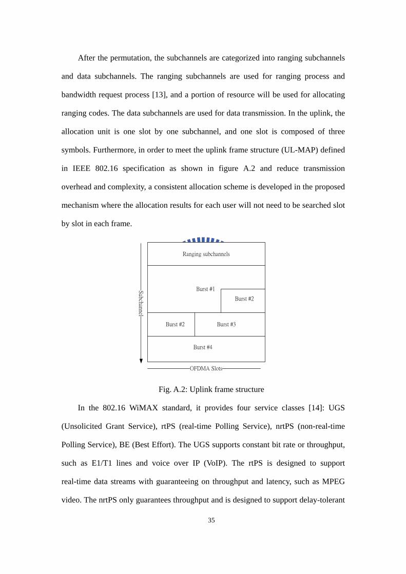
After the permutation, the subchannels are categorized into ranging subchannels
and data subchannels. The ranging subchannels are used for ranging process and
bandwidth request process [13], and a portion of resource will be used for allocating
ranging codes. The data subchannels are used for data transmission. In the uplink, the
allocation unit is one slot by one subchannel, and one slot is composed of three
symbols. Furthermore, in order to meet the uplink frame structure (UL-MAP) defined
in IEEE 802.16 specification as shown in figure A.2 and reduce transmission
overhead and complexity, a consistent allocation scheme is developed in the proposed
mechanism where the allocation results for each user will not need to be searched slot
by slot in each frame.
Ranging subchannels
Burst #1
Burst #2
Burst #2 Burst #3
Burst #4
Subchannel
OFDMA Slots
Fig. A.2: Uplink frame structure
In the 802.16 WiMAX standard, it provides four service classes [14]: UGS
(Unsolicited Grant Service), rtPS (real-time Polling Service), nrtPS (non-real-time
Polling Service), BE (Best Effort). The UGS supports constant bit rate or throughput,
such as E1/T1 lines and voice over IP (VoIP). The rtPS is designed to support
real-time data streams with guaranteeing on throughput and latency, such as MPEG
video. The nrtPS only guarantees throughput and is designed to support delay-tolerant
36
streams, such as Hypertext Transport Protocol (HTTP) service. The BE provides no
guarantees on throughput or delay, such as File Transfer Protocol (FTP). Generally
speaking, UGS, rtPS, nrtPS guarantee QoS , but BE doesn’t support QoS.
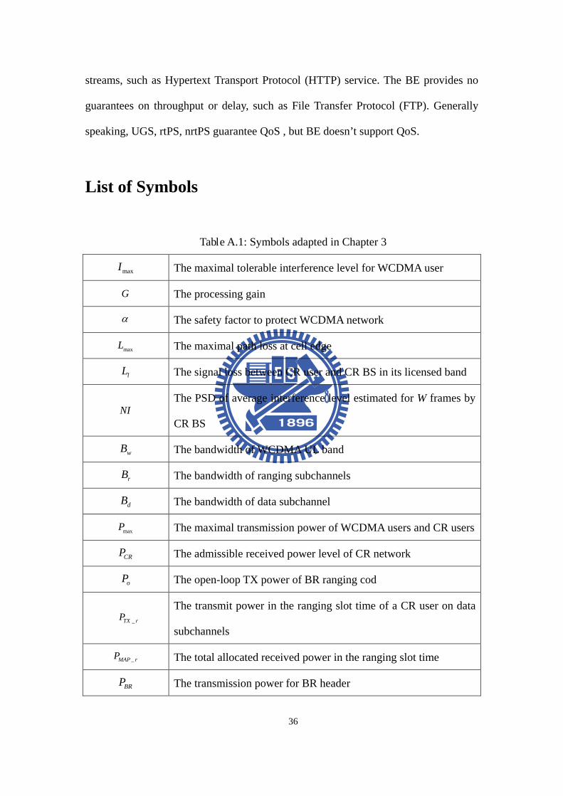
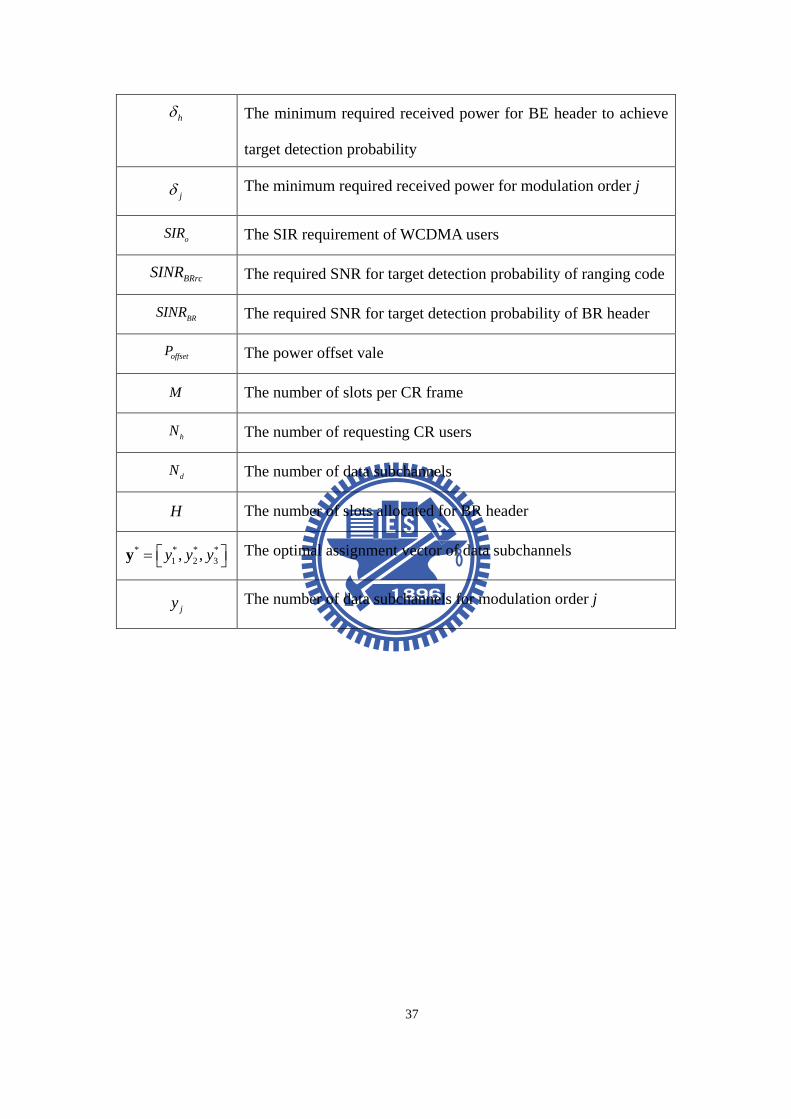
List of Symbols
Table A.1: Symbols adapted in Chapter 3
maxI The maximal tolerable interference level for WCDMA user
G The processing gain
α The safety factor to protect WCDMA network
maxL The maximal path loss at cell edge
lL The signal loss between CR user and CR BS in its licensed band
NI The PSD of average interference level estimated for W frames by
CR BS
wB The bandwidth of WCDMA UL band
rB The bandwidth of ranging subchannels
dB The bandwidth of data subchannel
maxP The maximal transmission power of WCDMA users and CR users
CRP The admissible received power level of CR network
oP The open-loop TX power of BR ranging cod
_TX rP The transmit power in the ranging slot time of a CR user on data
subchannels
_MAP rP The total allocated received power in the ranging slot time
BRP The transmission power for BR header
37
hδ The minimum required received power for BE header to achieve
target detection probability
jδ The minimum required received power for modulation order j
oSIR The SIR requirement of WCDMA users
BRrcSINR The required SNR for target detection probability of ranging code
BRSINR The required SNR for target detection probability of BR header
offsetP The power offset vale
M The number of slots per CR frame
hN The number of requesting CR users
dN The number of data subchannels
H The number of slots allocated for BR header
* * * *1 2 3, ,y y y = y The optimal assignment vector of data subchannels
jy The number of data subchannels for modulation order j
38
Bibliography [1] Federal Communications Commission, “Notice of proposed rule making and
order,” ET Docket No 03-222, Dec. 2003.
[2] S. Haykin, “Cognitive radio: brain-empowered wireless communications,” IEEE
Selected Areas in Communications, Vol . 23, Issue 2, pp. 201-220, Feb. 2005.
[3] P. Sutton, L.E. Doyle, and K.E. Nolan, “A reconfigurable platform for
cognitive networks,” International Conference on Cognitive Radio Oriented
Wireless Networks and Communications, pp. 1-5, Jun. 2006.
[4] I.F. Akyildiz, W.Y. Lee, M.C. Vuran, and S. Mohanty, “Next generation/dynamic
spectrum access/cognitive radio wireless networks: A survey,” Comput. Networks,
pp. 2127–2159, Sep. 2006.
[5] W. D. Horne, “Adaptive spectrum access: using the full spectrum space,” 31st
Annual Telecommunications Policy Research Conference (TPRC’03), Oct. 2003.
[6] Q. Zhao, L. Tong, A. Swami, and Y. Chen, “decentralized cognitive MAC for
opportunistic spectrum access in Ad Hoc networks: A POMDP Framework,” IEEE
Journal on Selected Areas in Communication: Special Issue on Adaptive,
Spectrum Agile and Cognitive Wireless Networks, Vol325, no. 3, April 2007.
[7] Z. Liang, W. Liu, P. Zhou, and F. Gao, “Randomized multi-user strategy for
spectrum sharing in opportunistic spectrum access network,” ICC’08, pp.
477 – 481, May 2008.
39
[8] Federal Communications Commission: “Spectrum policy task force”, Report ET
Docket, Nov. 2002.
[9] T. Clancy, “Formalizing the interference temperature model,” Wiley Wireless
Communication and Mobile Computing, PP. 1077 – 1086, May 2007
[10] P. Cheng, Z. Zhang, H. Chen, and P. Qiu, “Optimal distributed joint frequency,
rate and, power allocation in cognitive OFDMA systems,” Communications,
IET’08, pp. 815-826, July 2008.
[11] C. H. Lee, C. J. Chang, “Performance analysis of a truncated closed-loop
power-control scheme for DS/CDMA cellular systems,” IEEE Transactions on
Vehicular Technology, Vol. 53, No. 4, pp. 1149-1159, July 2004.
[12] IEEE Std. 802.16- 2004, “IEEE Standard for Local and Metropolitan Area
Networks Part 16: Air Interface for Fixed Broadband Wireless Access Systems,”
Oct. 2004.
[13] D. H. Lee and H. Morikawa, “Analysis of ranging process in IEEE 802.16e
wireless access systems,” MobiWAC’06, pp. 172-179, Oct. 2006.
[14] Q. Liu, X. Wang, and G.B. Giannakis, “A cross-layer scheduling algorithm with
QoS support in wireless networks,” IEEE Transactions on Vehicular
Technology, Vol. 55, No. 3, pp. 839-847, May 2006.
[15] A. J. Goldsmith and S. G. Chua, “Variable-rate variable-power MQAM for fading
channels,” IEEE Transactions on Communications, Vol. 45, pp.1218-1230, Oct.
1997.
[16] 3GPP TR 25.892, “Feasibility study for OFDM for UTRAN enhancement,” 3rd
Generation Partnership Project, Tech. Rep., 2004-06.
40
Vita
Shin-Yi Cheng was born on 1985 in Kaohsiung, Taiwan. He received the B.E. and
M.E. degree in department of communication engineering from National Chiao-Tung
University, Hsinchu, Taiwan, in 2007 and 2009, respectively. His research interests
include radio resource management and wireless communication systems.