Embed Size (px)
Citation preview

John McCann, McCann Imaging, USA.
Color Reproduction / Color Gamut Mapping:Two Sides of the Same Coin
Tuesday, October 20, 2009

Outline
• Color Reproduction & Gamut Mapping
• 3-D color spaces [One into Another]
• Practice
• Reproduce Paintings
• Gamut Mapping
• Theory
Tuesday, October 20, 2009

But first,CREATE
Colour Research for European Advanced Technology
Employment
New Ways to use Print Technology : (On Paper)
School of Creative Arts, University of the West of England Bristol (UK)
14 - 17th October, 2008
Tuesday, October 20, 2009

Allesandro Rizzi
Dip. Tecnologie dell’Informazione,Università degli Studi di Milano,
Italy
30
Carinna Parraman
Centre for Fine Print Research, University of the West of England,
UK
Tuesday, October 20, 2009

LDR
HDR
Measure appearances of constant reflectancesin different illuminations
Tuesday, October 20, 2009

Colour Constancy
Reflectance
Illumination
Eye
Eye Radiance= (Illumination * Reflectance)
Tuesday, October 20, 2009

Colour Constancy
Reflectance
Illumination
Eye
Eye Radiance= (Illumination * Reflectance)
Discount Illumination
SynthesizeReflectancefrom Edges
Tuesday, October 20, 2009

1968
Tuesday, October 20, 2009
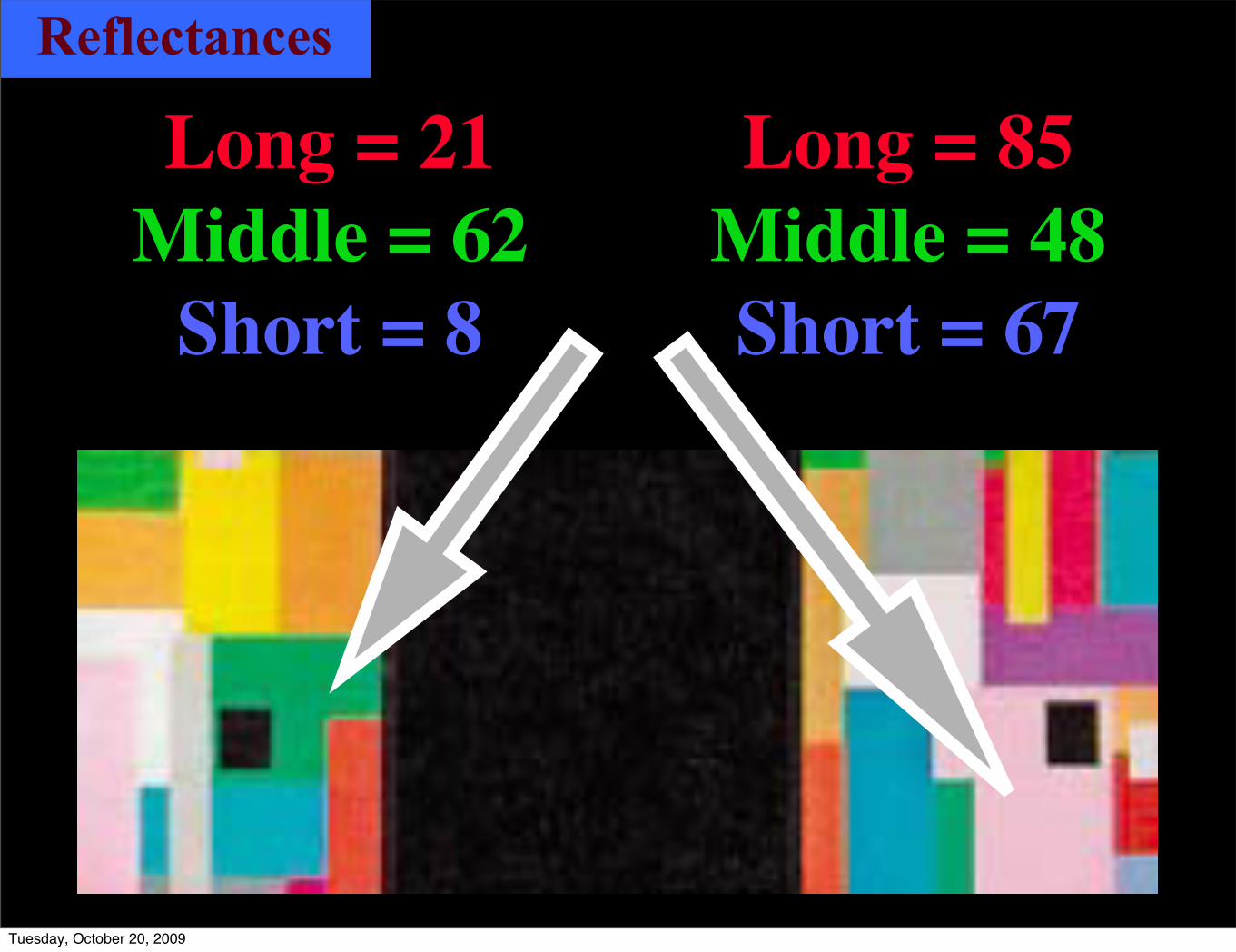
Reflectances
Long = 21Middle = 62
Short = 8
Long = 85Middle = 48Short = 67
Tuesday, October 20, 2009

Illuminations
Long = 85Middle = 48Short = 67
Long = 21Middle = 62
Short = 8
Tuesday, October 20, 2009

Mondrians Long = 53Middle = 55Short = 38
Tuesday, October 20, 2009

Mondrians Long = 53Middle = 55Short = 38
Color Constancy in complex
images
Tuesday, October 20, 2009

Tuesday, October 20, 2009

Tuesday, October 20, 2009
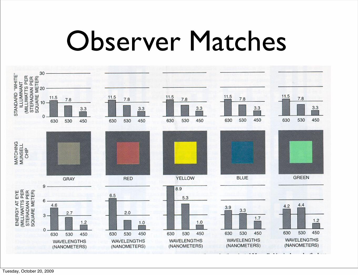
Observer Matches
Tuesday, October 20, 2009

Tuesday, October 20, 2009

Appearance = Reflectance ?
• Yes
Reflectance predicts appearance for flat Mondrians and the Munsell Book of Colors,
in uniform illumination.
McCann, McKee, and Taylor, Vision Res, 1976
Tuesday, October 20, 2009

Reflectance is defined as the ratio of
incident flux on a sample surface to reflected flux from the surface
Reflectance
Tuesday, October 20, 2009

Reflectance is defined as the ratio of
incident flux on a sample surface to reflected flux from the surface
No one measuresReflectance
Tuesday, October 20, 2009

Practical measurementsReflectance relative to a standard
Photocell
Object Illumination
LensStep 1: Radiance from Object
Tuesday, October 20, 2009

People measureReflectance relative to a standard
Lens PhotocellStep 2: Radiance from White
Object Illumination
Tuesday, October 20, 2009

Object Illumination
Object Illumination
LensRadiance from ObjectRadiance from White
Relative Reflectance =
Tuesday, October 20, 2009

Retinex Replace temporal with spatial
Calculate relative reflectance
by spatial comparisons
Lx,y / Lx*,y*
Lx,y
Lx*,y*
E. H. Land & J. J. McCann “Lightness and Retinex Theory”, J. Opt. Soc. Am. 61 1-11, 1971.
Tuesday, October 20, 2009

X, Y, Z pixel color
color
X separation
Y separation
Z separation
Pixel-based Colorimetry
Spatial-comparison Retinex
Tuesday, October 20, 2009

Auto-normalize with reset to maximaTuesday, October 20, 2009

Tuesday, October 20, 2009

Tuesday, October 20, 2009

LDR
HDR
Measure appearances of constant reflectancesin different illuminations
Tuesday, October 20, 2009

Tuesday, October 20, 2009

LDR HDRscenes
11 reflectances (paints)2 identical sets of blocks
>200 facetsTuesday, October 20, 2009
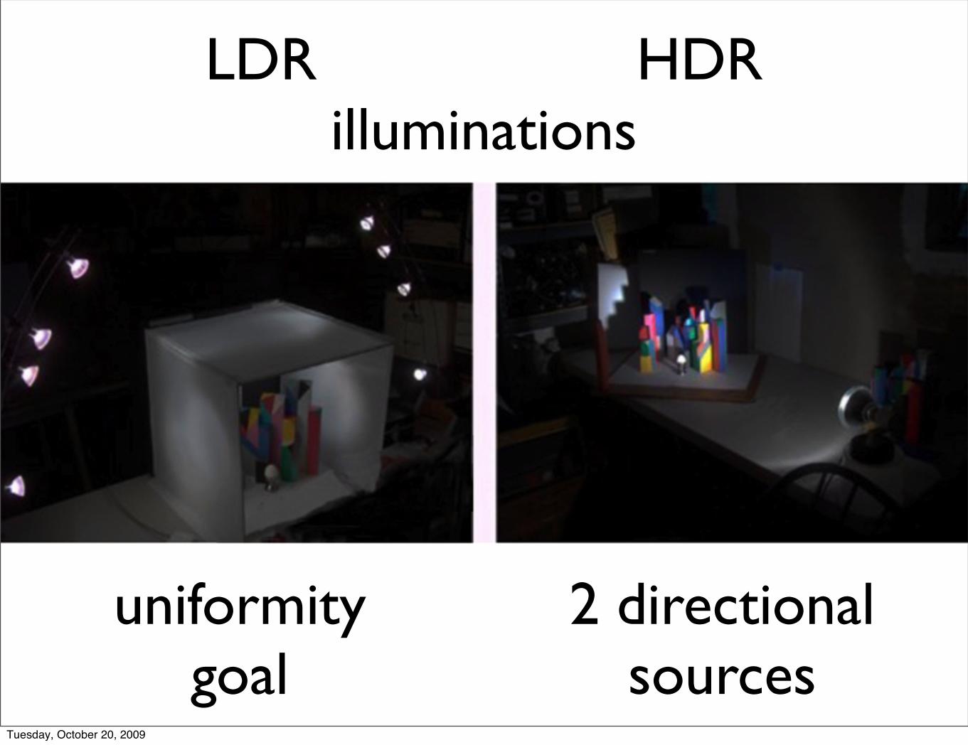
uniformitygoal
LDR HDRilluminations
2 directionalsources
Tuesday, October 20, 2009

The world’s only gray world
LDR HDRillumination
Tuesday, October 20, 2009

LDR HDRscenes
Measure appearances of constant reflectancesin different illuminations
Tuesday, October 20, 2009

Tuesday, October 20, 2009

Tuesday, October 20, 2009
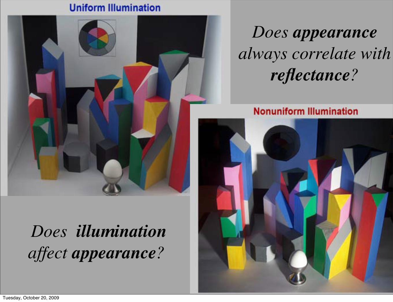
Does illumination affect appearance?
Does appearance always correlate with
reflectance?
Tuesday, October 20, 2009

LDR
HDR
Multiple Exposures (x2)
Tuesday, October 20, 2009

LDR
HDR
Tuesday, October 20, 2009

Tuesday, October 20, 2009

LDR
HDR
Tuesday, October 20, 2009

14th October 2008Workshop 1 : Camera Capture and HDR WorkshopJohn McCann, Alessandro Rizzi, Carinna Parraman
(John McCann Imaging; Università Degli Studi Di Milano; CFPR, UWE)
Tuesday, October 20, 2009

Select Areas - LDR
GroundTruth
Tuesday, October 20, 2009

Select Areas - HDR
Tuesday, October 20, 2009

Select Areas - LDR
Tuesday, October 20, 2009

Select Areas - HDR
Tuesday, October 20, 2009

11 Paints
Tuesday, October 20, 2009

MLAB distance from constancy
MLAB coordinates
Munsell Chip Estimate of Appearance
Observed changes in Appearance
Munsell Notation of 11 paints
Tuesday, October 20, 2009

LDR / HDR Departures of Appearance from Reflectance
MLAB isotropic color spaceTuesday, October 20, 2009

LDR / HDR Departures 2
Tuesday, October 20, 2009
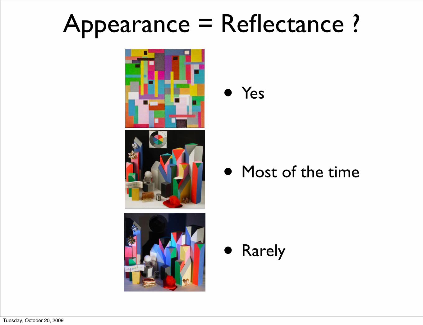
Appearance = Reflectance ?
• Yes
• Most of the time
• Rarely
Tuesday, October 20, 2009

Two Questions about Colour Constancy?
• Does an object’s appearance = reflectance ?
• Only in perfectly uniform illumination
• Small changes observed in LDR
• Large changes in HDR
• Are appearances constant for all illuminants ?
• No
• Large changes in lightness, hue and chroma
Tuesday, October 20, 2009

Tuesday, October 20, 2009

Tuesday, October 20, 2009

Appearance = ?????
•Appearance ≠ Reflectance•Multiple reflections
•White reflectance•Appears white•Appears cool gray•Appears magenta•Appears yellow
Tuesday, October 20, 2009

Tuesday, October 20, 2009

LDR
HDR
Tuesday, October 20, 2009

Tuesday, October 20, 2009

Tuesday, October 20, 2009

Appearance = ?????
•Appearance ≠ Reflectance•Illumination edges
•Gray reflectance•Appears light gray•Appears dark gray•Appears black
• Illumination changes order of appearances
Tuesday, October 20, 2009

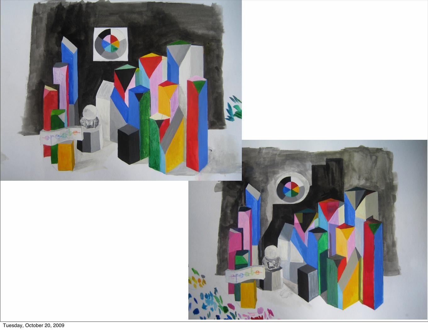
Measure LDR & HDR appearancesby painting with watercolors
Tuesday, October 20, 2009

Two Watercolor Renditions LDR HDRscene scene
Tuesday, October 20, 2009
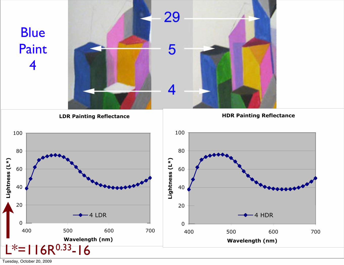
BluePaint
4
LDR Painting Reflectance
0
20
40
60
80
100
400 500 600 700
Wavelength (nm)
Lig
htn
ess
(L*
)
4 LDR
HDR Painting Reflectance
0
20
40
60
80
100
400 500 600 700
Wavelength (nm)
Lig
htn
ess
(L*
)
4 HDR
L*=116R0.33-16Tuesday, October 20, 2009

BluePaint
4 & 29
LDR Painting Reflectance
0
20
40
60
80
100
400 500 600 700
Wavelength (nm)
Lig
htn
ess
(L*
)
4 LDR 29 LDR
HDR Painting Reflectance
0
20
40
60
80
100
400 500 600 700
Wavelength (nm)
Lig
htn
ess
(L*
)
4 HDR 29 HDR
Tuesday, October 20, 2009

BluePaint4 & 5
29
LDR Painting Reflectance
0
20
40
60
80
100
400 500 600 700
Wavelength (nm)
Lig
htn
ess
(L*
)
4 LDR 5 LDR 29 LDR
HDR Painting Reflectance
0
20
40
60
80
100
400 500 600 700
Wavelength (nm)
Lig
htn
ess
(L*
)
4 HDR 5 HDR 29 HDR
Tuesday, October 20, 2009

Watecolor Reflectances in LDR
0
20
40
60
80
100
400 500 600 700Wavelength (nm)
Lig
htn
ess
(L*
)
7 8 11
Watecolor Reflectances in HDR
0
20
40
60
80
100
400 500 600 700
Wavelength (nm)
Lig
htn
ess
(L*
)
7 8 11
GreenPaint
Tuesday, October 20, 2009

RedPaint
LDR Painting Reflectance
0
20
40
60
80
100
400 500 600 700
Wavelength (nm)
Lig
htn
ess
(L*
)
12 LDR 22 LDR 35 LDR
HDR Painting Reflectance
0
20
40
60
80
100
400 500 600 700
Wavelength (nm)
Lig
htn
ess
(L*
)
12 HDR 22 HDR 35 HDR
Tuesday, October 20, 2009

Watecolor Reflectances in LDR
0
20
40
60
80
100
400 500 600 700Wavelength (nm)
Lig
htn
ess
(L*
)
19 21 25
Watecolor Reflectances in HDR
0
20
40
60
80
100
400 500 600 700Wavelength (nm)
Lig
htn
ess
(L*
)
4H 5H 29H
MagentaPaint
Tuesday, October 20, 2009

LDR Painting Reflectance
0
20
40
60
80
100
400 500 600 700
Wavelength (nm)
Lig
htn
ess
(L*
)
30 LDR 32 LDR 33 LDR
18 LDR 9LDR
HDR Painting Reflectance
0
20
40
60
80
100
400 500 600 700
Wavelength (nm)
Lig
htn
ess
(L*
)
30 HDR 32 HDR 33 HDR
18 HDR 9 LDR
LDR HDR
Tuesday, October 20, 2009

Tuesday, October 20, 2009
Tuesday, October 20, 2009

Tuesday, October 20, 2009

Appearance = Reflectance ?
• Yes
• Most of the time
• Rarely
Tuesday, October 20, 2009

Do humans discount illumination?
NoTuesday, October 20, 2009

Colour Constancy: 3 Types of Models
Model CalculationGoal
[Output]
Given Information
[Input]
Reference
Retinex appearanceradiance arrayof entire scene Land, 1971
Discount Illumination
CIELABCIECAM
appearancepixel’s radiance
+ pixel’s irradiance
CIE, 1976CIE 1997,2002
Computer Vision
reflectance radiance arrayof entire scene
Ebner, Funt, Finlayson,
Drew, 1998
Tuesday, October 20, 2009

Colour Constancy: 3 Types of Models
ModelCalculation
Goal[Output]
Mechanism [Output] = Reflectance
Retinex appearance build appearance from edges
sometimes
Discount Illumination
CIELABCIECAM
appearance measure reflectancestretch
always
Computer Vision
reflectanceestimate illumination
to calculate reflectance
always
Tuesday, October 20, 2009
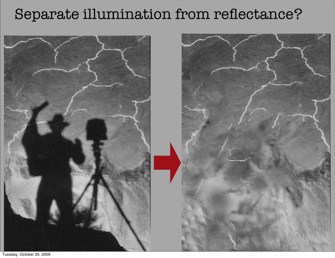
Separate illumination from reflectance?
Tuesday, October 20, 2009

Vassillos Image Processing
Tuesday, October 20, 2009

Vassillos Image Processing
Tuesday, October 20, 2009

Tuesday, October 20, 2009
Color Reproduction
• 3-D Color Space [One into Another]
Tuesday, October 20, 2009

Colorant Systems
Tuesday, October 20, 2009

Interpolate Primaries
3-D Graphics, Bob Sobol, HP EmeritasTuesday, October 20, 2009

But, Real Primaries
Tuesday, October 20, 2009

But, Real Primaries75%R * 75%G * 75%B
75% * 75% * 75% = 42.2%
Tuesday, October 20, 2009
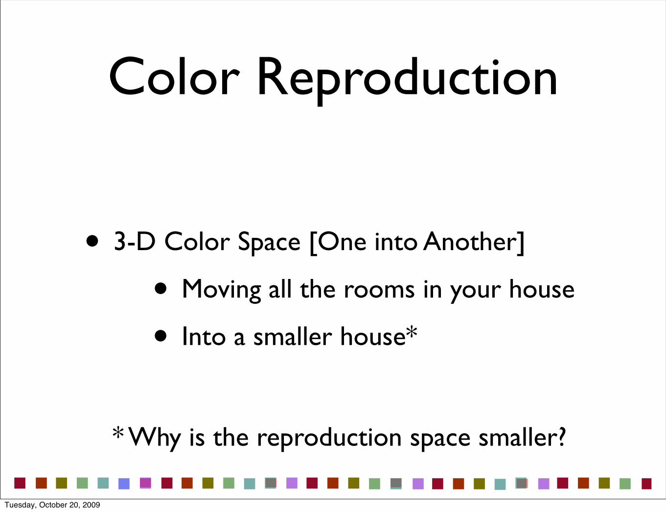
Color Reproduction
• 3-D Color Space [One into Another]
• Moving all the rooms in your house
• Into a smaller house*
* Why is the reproduction space smaller?
Tuesday, October 20, 2009

*Smaller space?
• Colorants - Physical spectra
• Gamut limits
• Unwanted absorptions
• Tone scale [Contone, Halftone, Transfer]
• Media [Print and display technologies]
• Surface properties limit range
• Veiling glare limits range
Tuesday, October 20, 2009

Outline
• Color Reproduction & Gamut Mapping
• 3-D color spaces [One into Another]
• Practice
• Reproduce Paintings
• Gamut Mapping
• Theory
Tuesday, October 20, 2009

How the Print represents the WorldLightin theWorld
Film &Camera
• Reproducing paintings should be easy
• AgX photography
• Both are reflective
• Similar gamuts
• Expect good results
• Minimum effortTuesday, October 20, 2009
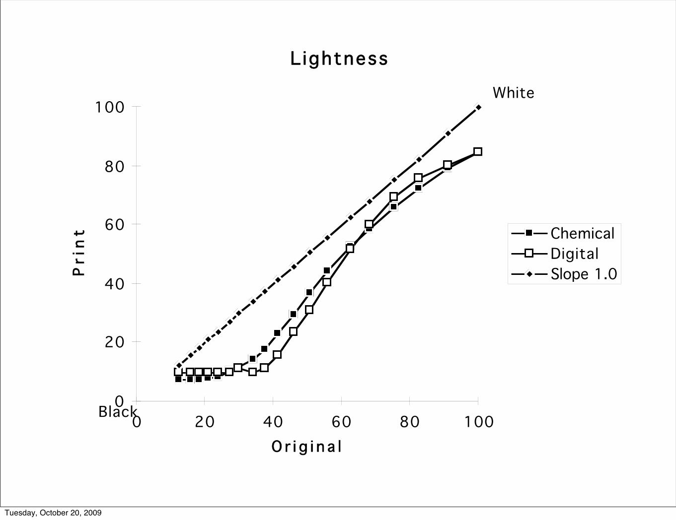
Lightness
0
20
40
60
80
100
0 20 40 60 80 100O r i g i n a l
Pri
nt Chemical
DigitalSlope 1.0
Black
White
Tuesday, October 20, 2009
Lightness
0
20
40
60
80
100
0 20 40 60 80 100O r i g i n a l
Pri
nt Chemical
DigitalSlope 1.0
Black
White
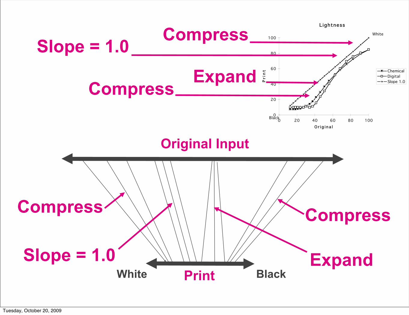
Expand
Compress
Compress
Slope = 1.0
CompressCompress
Slope = 1.0
Original Input
PrintExpand
White Black
Tuesday, October 20, 2009

Optical Density
0.00
0.50
1.00
1.50
2.00
2.50
0.00 0.50 1.00 1.50 2.00 2.50O r i g i n a l
Pri
nt Chemical
DigitalSlope 1.0
Black
White
Tuesday, October 20, 2009

S-curve enhances colorOptical Density
O r i g i n a l
Pri
nt
0.00
0.50
1.00
1.50
2.00
2.50
0.00 0.50 1.00 1.50 2.00 2.50
Chemical
Slope 1.0
Black
White
Optical Density
O r i g i n a l
Pri
nt
0.00
0.50
1.00
1.50
2.00
2.50
0.00 0.50 1.00 1.50 2.00 2.50
Chemical
Slope 1.0
Black
White
Optical Density
O r i g i n a l
Pri
nt
0.00
0.50
1.00
1.50
2.00
2.50
0.00 0.50 1.00 1.50 2.00 2.50
Chemical
Slope 1.0
Black
White
.05 in
0.6out
1.25 in
1.80 out
1.25 in
1.80 out
Optical Density
O r i g i n a l
Pri
nt
0.00
0.50
1.00
1.50
2.00
2.50
0.00 0.50 1.00 1.50 2.00 2.50
Chemical
Slope 1.0
Black
White
0.5 1.25 1.25
In Out
0.6 1.80 1.80
Tuesday, October 20, 2009

The story of how Replicas are made starts with a trip to the Museum. This is the main entrance to the Museum of Fine Arts, Boston. In addition, Replicas in this exhibit were made from photographs taken at the National Gallery, Washington and the Pushkin Museum, Moscow.
Polaroid Replicas
Tuesday, October 20, 2009

The Replica photographer uses an 8x10, or larger camera with a special light source to uniformly illuminate the painting.
Tuesday, October 20, 2009

In order to generate the feeling of depth the light must be both uniform and come from above the painting.
Look at the shadow cast by the light above the painting. The eye reads that shadow and makes the paint look “Three Dimensional.”
Tuesday, October 20, 2009

In order to record enough information about the actual colors in the painting, the photographer first makes a photograph of this 512 color calibration target. He places the target in front of the painting in the same light that will be used to photograph the painting.
Tuesday, October 20, 2009

This is a photograph of the Monetʼs “ Field of Poppies near Giverney” from the White Fund, housed at the Museum of Fine Arts, Boston.
Tuesday, October 20, 2009

This is the optical head of the digital drum scanner that records the image as digits. The scanner divides the photograph into 100 million picture elements--pixels. Each square pixel is 1/1200 of an inch on a side. Red, green and blue records have 256 levels -- 8 bits. We converted the photographic image to a 300 megabyte digital file.
Tuesday, October 20, 2009

This diagram shows how the each calibration color patch in the test target was created by a number (ie, 255,50,50) sent to a film recorder.
Start Here
DigitTriplet
255,50,50
Red DigitTriplet
239, 62,28
ApplyTransform
FilmTarget
Printer
Red
FilmPhoto of Painting & Target
CalculateTransform
Camera Scanner
“Master”Positive Tranparency
The scan of photo produces a new number (239,62,28). The calibration program calculates the effects of film, illumination, and processing. The transform board stores the calibration instructions and uses them to convert scanner digits to new output digits that remove color distortion.
Tuesday, October 20, 2009

We now convert the 300 megabyte digital file back to a new 'Master' photographic transparency. The FIRE 1000 film recorder writes a new 8x10 positive transparency (1200 dpi) that contains all the corrections from the calibration. It anticipates the characteristic of the print film so that the final image looks exactly like the original painting.
Tuesday, October 20, 2009
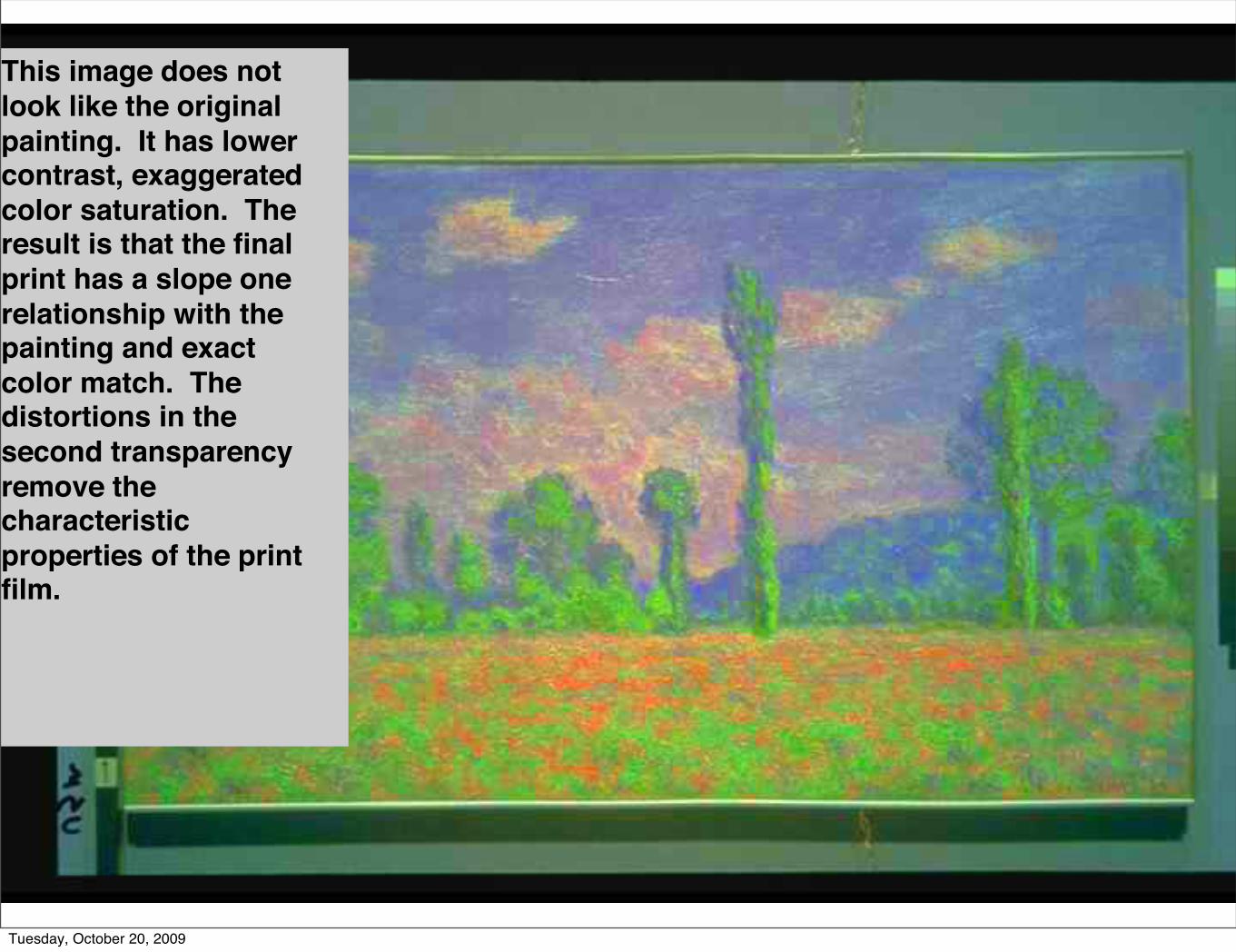
This image does not look like the original painting. It has lower contrast, exaggerated color saturation. The result is that the final print has a slope one relationship with the painting and exact color match. The distortions in the second transparency remove the characteristic properties of the print film.
Tuesday, October 20, 2009

This diagram shows the giant Polaroid processor in the room-size camera.
The light sensitive film--negative is at the top. The positive print paper is at the bottom. The chemical reagent, or developer, is applied between the positive and the negative. After the shutter opens, the strobe behind the transparent master discharges, and the shutter closes, the operator turns on a motor that drives a pair of titanium rolls that marries the positive and negative sheets and meters a precise amount of reagent between the sheets. The operator turns on the lights inside the camera, while the combine positive and negative are held in the air.
Role of photosensitive material-negative
Reagent Layer
Lens
Role of positve print paper
Film in exposure position
PressureRolls
Tuesday, October 20, 2009
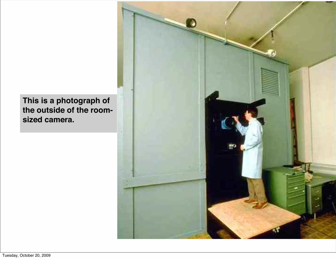
This is a photograph of the outside of the room-sized camera.
Tuesday, October 20, 2009

The Replica photograph is held in the air with a line and pulley.
The print paper is white and the negative is black. Both are opaque.
The technicians turn on the lights, place the print on the floor, and wait 90 seconds for the dyes to transfer from the negative to the positive.
Tuesday, October 20, 2009

Two technicians peel away the black-backed negative leaving a finished actual-size reproduction of the painting.
Tuesday, October 20, 2009

The photograph is mounted on an archival board, spayed with a matte surface UV absorbing material. It is the placed in a hand-crafted frame for display.
Tuesday, October 20, 2009

Color PrintingCalibration
Tuesday, October 20, 2009
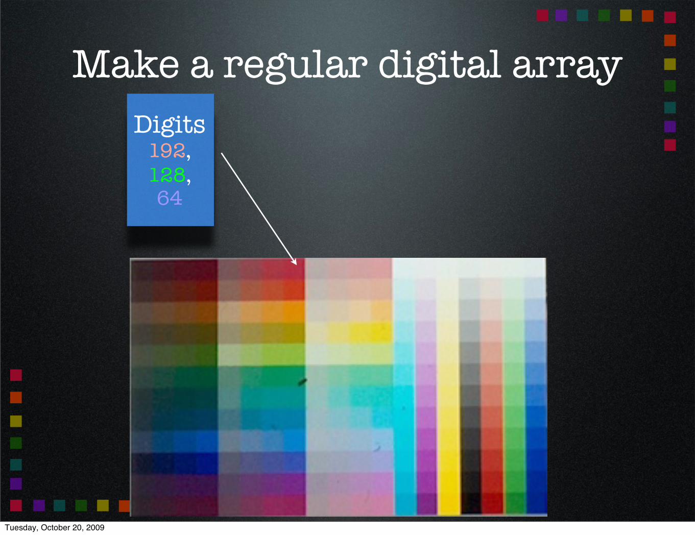
Make a regular digital arrayDigits
192,128,64
Tuesday, October 20, 2009

Tuesday, October 20, 2009

Closed Loop Calibration
Digits192,128,64
In
Digitsr,gb
Out 3D LUT
Digits192,128,64
Tuesday, October 20, 2009

3D LUT[ LookUp Table ]
R -
B - |
G
R G Bin
Find Nearest Neighbors1R G B = 1DENR DENG DENB2R G B = 2DENR DENG DENB3R G B = 1DENR DENG DENB4R G B = 3DENR DENG DENB5R G B = 4DENR DENG DENB6R G B = 5DENR DENG DENB7R G B = 6DENR DENG DENB7R G B = 7DENR DENG DENB8R G B = 8DENR DENG DENB
DENR DENG DENB
out
Interpolate
Tuesday, October 20, 2009

Film
Recorder
Digits192,128,64
Digits222,99,105
3D LUT
GraphicsArt
Scanner
transparency print
8x10View
Camera
Enlarger
transparency
MFA Monet original
Tuesday, October 20, 2009

Film
Recorder
Digits192,128,64
Digits222,99,105
3D LUT
GraphicsArt
Scanner
transparency print
Enlarger
transparency
MFA Monet original
Tuesday, October 20, 2009

MFA Monet original Replica
=
Tuesday, October 20, 2009

3D LUTP.C. Pugsley, Image reproduction
methods and Apparatus, British patent, 1,369,702(1974).
Kang, Color Technology of the Electronic Imaging Device
Tuesday, October 20, 2009

Printer with 3D LUTM. Abdulwahab, J. L. Burkhardt and J. J. McCann,
Method and Apparatus for Transforming Color Image Data on the Basis of an Isotropic and Uniform
Colorimetric Space, U. S. Patent, 4,839,721, Jun.13,1989
Tuesday, October 20, 2009

Kotera et. al.K.Kanamori, H.Kawakami, and H.Kotera:"A Novel Color
Transformation Algorithm and Its Applications", Proc. SPIE., vol.1244,p.272-281(1990) ;
K.Kanamori and H.Kotera:"Color Correction Technique for Hard Copies by 4-Neighbors Interpolation Method", Jour.Imag.Sci.&Tech., 36,1, p.73-80(1992);
K.Kanamori, H.Kotera, O.Yamada, H.Motomura, R.Iikawa, T.Fumoto: "Fast Color Processor with Programmable Interpolation by Small Memory(PRISM)", Jour.Electronic Imaging, vol. 2(3), pp.213-224(1993);
H.Kotera,K.Kanamori,T.Fumoto,O.Yamada,H.Motomura and M.Inoue:"A Single Chip Color Processor for Device Independent Color Reproduction",Proc. 1 st CIC, p.133-137(1993);
T.Fumoto, K.Kanamori, O.Yamada, H.Motomura, and H.Kotera : "SLANT/PRISM Convertible Structured Color Processor MN5515, Proc. 3rd CIC, p.101-105(1995).
Tuesday, October 20, 2009

Outline
• Color Reproduction & Gamut Mapping
• 3-D color spaces [One into Another]
• Practice
• Reproduce Paintings
• Excellent results - 3D LUTS
• Each “room” separately
• See approach in device profiles
Tuesday, October 20, 2009

Observations
• A. Color reproduction is like moving into a smaller house
• We cannot just shrink everything to fit
• Different solution for each room*
• Color
• 3-D lut [very powerful and affordable]
• Best reproductions preserve edges
Tuesday, October 20, 2009

Outline
• Color Reproduction & Gamut Mapping
• 3-D color spaces [One into Another]
• Practice
• Reproduce Paintings
• Gamut Mapping
• Theory
Tuesday, October 20, 2009

Color Display Gamut
Tuesday, October 20, 2009

SWOP (coated) Gamut
Tuesday, October 20, 2009

Original / Reproduction
Perfect
A Ar BrB
Ar = A Br = B
Ar / Br = A / B
89 95 89 95
Tuesday, October 20, 2009

Conserverve X,Y,Z
89 95 89
85
A Ar BrB
Ar = A Br = .9B
Ar / Br ≠ A / B
85
Out of gamutSubstitute
Tuesday, October 20, 2009

89 95
Out of gamutSubstitutes
Conserve Spatial Ratio A Ar BrB
80 85
Ar = .9A Br = .9B
Ar/Br = A / BTuesday, October 20, 2009
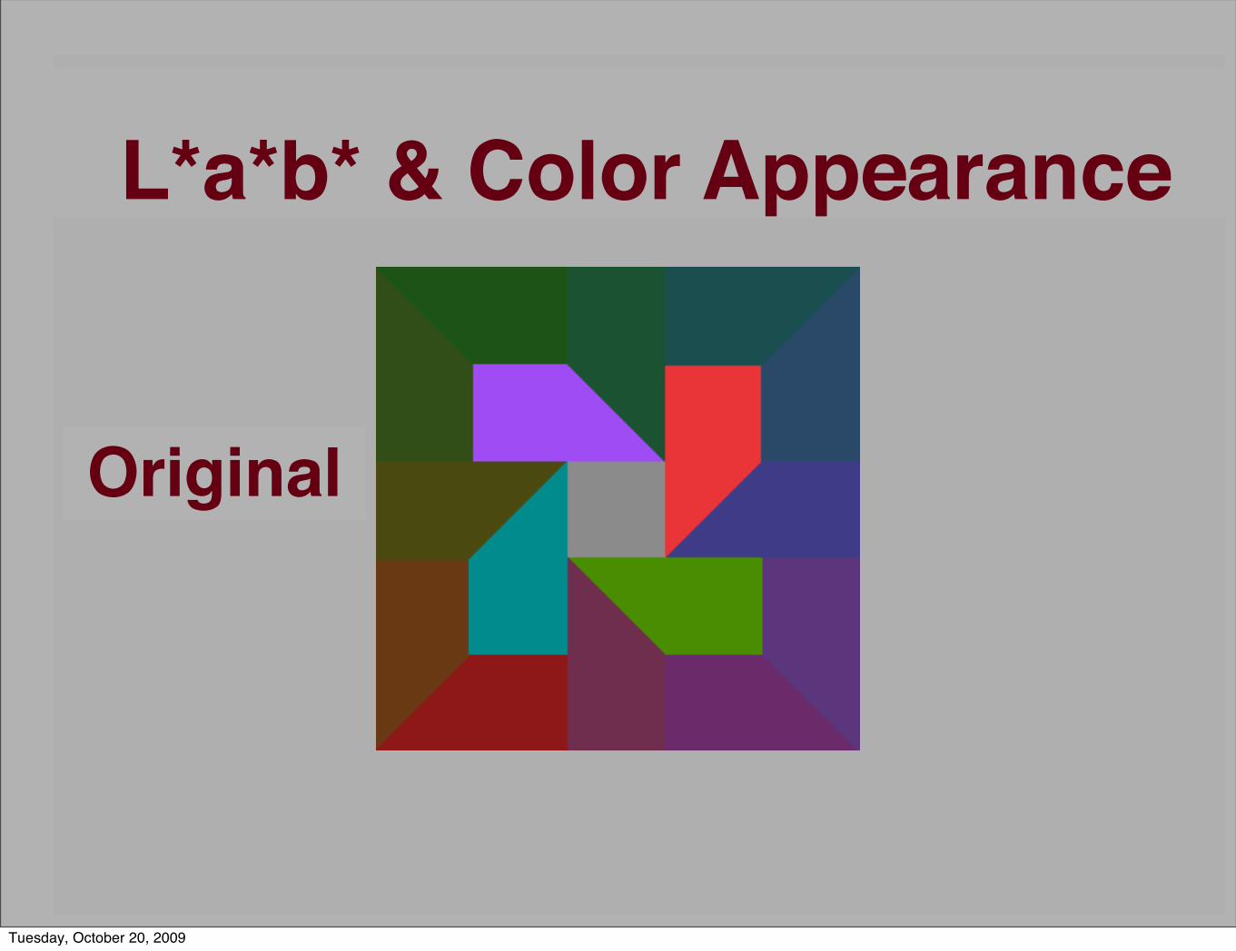
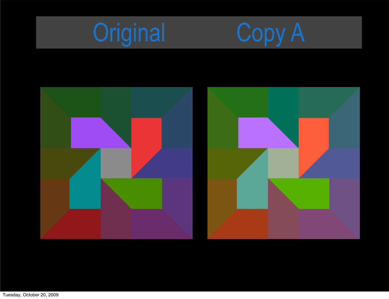
L*a*b* & Color Appearance
Original
Tuesday, October 20, 2009

Copy A Copy B
∆ECopy A = ∆ECopy BTuesday, October 20, 2009

Original Copy A
Tuesday, October 20, 2009

Original Copy B
Tuesday, October 20, 2009

17 Areas
∆ECopy A = ∆ECopy B
∆E ∆EArea [Or ig&CopyA] [Or ig&CopyB]
1 17 .3 17 .02 17 .0 17 .23 15 .2 17 .94 17 .3 17 .35 18 .5 17 .56 16 .2 18 .07 17 .9 15 .78 17 .3 17 .59 17 .3 18 .0
1 0 17 .3 17 .51 1 17 .3 17 .31 2 17 .3 18 .01 3 17 .3 17 .51 4 17 .3 16 .51 5 17 .3 18 .01 6 17 .3 17 .91 7 17 .3 17 .3
Average 17 .2 17 .4
Tuesday, October 20, 2009
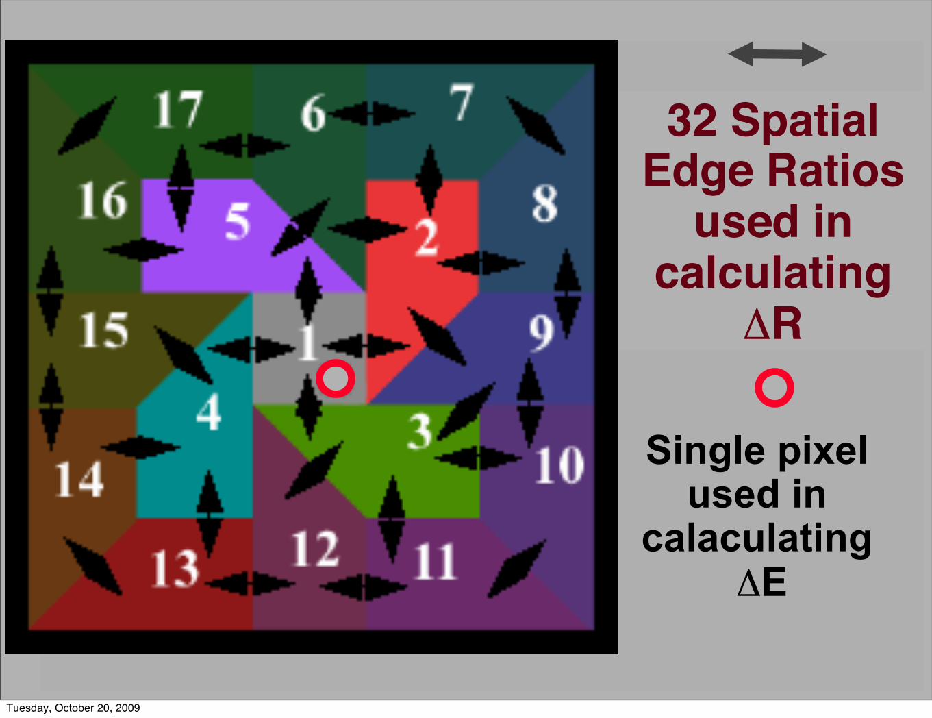
32 SpatialEdge Ratios
used in calculating
ΔR
Single pixel used in
calaculating ΔE
Tuesday, October 20, 2009
Original Copy A
Tuesday, October 20, 2009

Original Copy B
Tuesday, October 20, 2009

Lab Copy
X’Y’Z’
XYZ
Copy
XYZ
X’Y’Z’
Original XO/X’ O
XC/X’ C
2)YC/ Y′CYO/ Y′O(1- +√ΔR= )2(1- ZC/ Z′C
ZO/ Z′O+2)XC/ X′C
XO/ X′O(1-
Lab Original
√ΔE= +)2(aC- aO+L C- L O)2( bC- bO)2(
ΔR compares RatiosΔE compares Pixels
Tuesday, October 20, 2009

L*a*b*pixel
Lightin theWorld
Retinexfield
=
Tuesday, October 20, 2009

5 R5 YR5 Y5 GY5 G5 BG5 B5 PB5 P5 RP
Munsell
7/6
Tuesday, October 20, 2009

Conserve Spatial Ratio Lightness
OriginalOriginal+ 1 M chip
Original- 1 M chip
Tuesday, October 20, 2009

Conserve Spatial Ratio Chroma
OriginalOriginal- 1 M chip
Original+ 1 M chip
Tuesday, October 20, 2009

Conserve Spatial Ratio Hue
OriginalOriginal- 1 M chip
Original+ 1 M chip
Tuesday, October 20, 2009

Alter Spatial Ratio Random
OriginalOriginal- 1 M chip
Original+ 1 M chip
Tuesday, October 20, 2009

Calculating the best extra-gamut colors
using spatial comparisons
[Retinex]
Tuesday, October 20, 2009

The Experiment
BestIn . tiff
GoalIn, tiff
Tuesday, October 20, 2009

Toyo Inks (uncoated)
BestIN . tiff
GAMUTWARNING
Tuesday, October 20, 2009

1. Create Multi-resolution BestIn
Tuesday, October 20, 2009

2. Create Multi-resolution GoalIn
Tuesday, October 20, 2009

Retinex Color Gamut
Tuesday, October 20, 2009

3. Separate r, g, b channels
create r, g, b color-separation channels
Tuesday, October 20, 2009

-create r, g, b color-separation channels
Tuesday, October 20, 2009

Tuesday, October 20, 2009
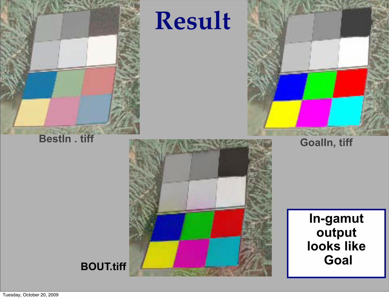
Result
BestIn . tiff GoalIn, tiff
BOUT.tiff
In-gamut output
looks like Goal
Tuesday, October 20, 2009

GOAL BEST
SWOP coated
Tuesday, October 20, 2009

GOAL BEST
SWOP coated
Tuesday, October 20, 2009

LUT
Tuesday, October 20, 2009

LUT
Tuesday, October 20, 2009

GOAL
BEST GamutRetinex
Tuesday, October 20, 2009

GOAL
BEST
GamutRetinex
Tuesday, October 20, 2009

Lessons
Searching for matching color appearances using spatial comparisons (Retinex) finds in-gamut images that do look like the Goal.
Reason: Gamut Retinex uses the spatial relationships that control human color appearance.
It uses spatial comparisons as input from the Goal image.
Tuesday, October 20, 2009

LessonsColor matches (CIE) for extra-gamut colors
do not look like the Goal image colors.
Reason
Color matches (CIE) are calculated one pixel at a time.
The relationship to other pixels is ignored.
The CIE process distorts the spatial relationships that control human color appearance.
Tuesday, October 20, 2009
Corollary 1 The only time that CIE color matches will
make a reproduction look exactly like the original is when all the individual pixels match.
Reason: Any extra-gamut pixel will introduce new spatial relationships with the rest of the image that are different from those of the original.
These relationships can distort the appearance of the entire image.
Tuesday, October 20, 2009

Corollary 2 When spatial comparisons (Retinex) finds in-gamut images that do look like the Goal, it will significantly
increase the deltaE of corresponding pixels.
Reason: In order to get the correct relationships throughout the image the calculation will increase delta E for in-gamut pixels.
Tuesday, October 20, 2009

Observations
• A. Color reproduction is like moving into a smaller house
• We cannot just shrink everything to fit
• Different solution for each room*
• Color
• 3-D lut [very powerful and affordable]
• Best reproductions preserve edges
• B. Color gamut mapping is like Color reproduction
Tuesday, October 20, 2009

• A. Color reproduction is like moving into a smaller house
• We cannot just shrink everything to fit
• Different solution for each room*
• Color
• Different optimization for each room
• 3-D lut [very powerful and affordable]
• Best reproductions preserve edges
• B. Color gamut mapping is like Color reproduction
• C. Best done in an isotropic color space [UCS]
Observations
Tuesday, October 20, 2009

Outline
• Color Reproduction & Gamut Mapping
• 3-D color spaces [One into Another]
• Practice
• Reproduce Paintings
• Gamut Mapping
• Theory
Tuesday, October 20, 2009

Theory
• Colorant Primaries
• Interpolate in 3-D color spaces
Tuesday, October 20, 2009

Colorant Systems
Tuesday, October 20, 2009

Subtractive
Tuesday, October 20, 2009

Subtractive
Tuesday, October 20, 2009

Subtractive
Tuesday, October 20, 2009

Newsprint
Tuesday, October 20, 2009

Halftone
Tuesday, October 20, 2009

Theory• Colorant Primaries• Interpolate in 3-D color spaces
• [Which one ??????]• Should be visually isotropic• e.g. We can average data• Uniform Color Space [UCS]
• Munsell Space• LMS Cones• XYZ• CIELAB• CIECAM
Tuesday, October 20, 2009

• Uniform Color Space [UCS]• Munsell Space
Dorothy Nickerson, 1943
Tuesday, October 20, 2009

Spectral Sensitivity
Maxwell 1860
CIE 1931Brown Wald 1970
Color Theory
Data
Tuesday, October 20, 2009

Tuesday, October 20, 2009
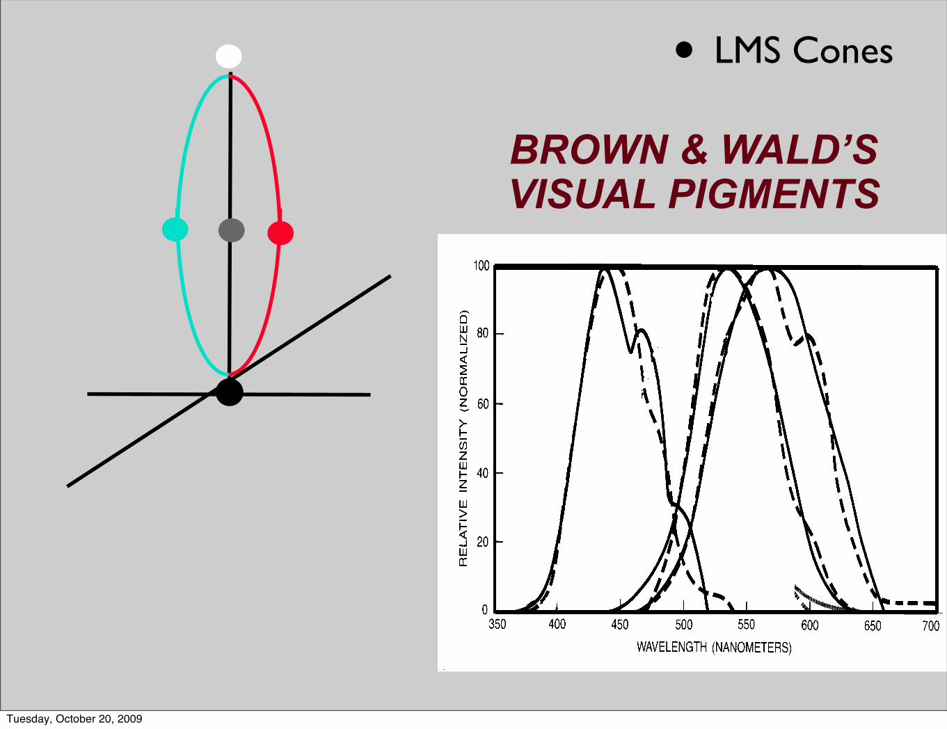
BROWN & WALD’SVISUAL PIGMENTS
• LMS Cones
Tuesday, October 20, 2009

WRIGHT’SCOLOR MATCHES
CIE 1931
X, Y, Z space
Tuesday, October 20, 2009
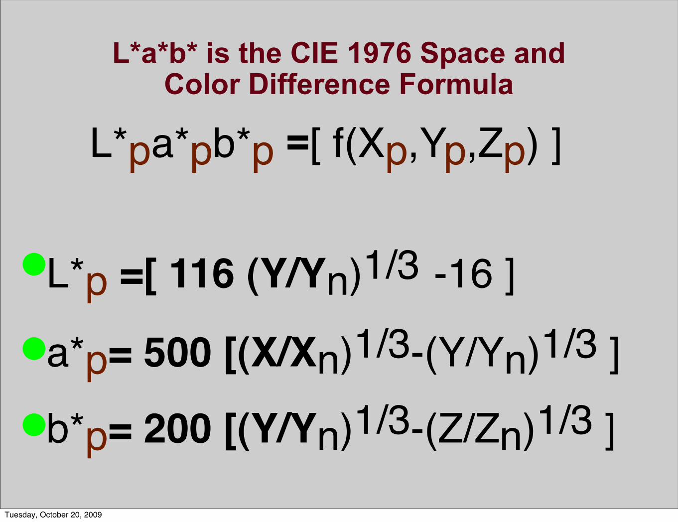
L*p =[ 116 (Y/Yn)1/3 -16 ]a*p= 500 [(X/Xn)1/3-(Y/Yn)1/3 ]b*p= 200 [(Y/Yn)1/3-(Z/Zn)1/3 ]
L*pa*pb*p =[ f(Xp,Yp,Zp) ]
L*a*b* is the CIE 1976 Space and Color Difference Formula
Tuesday, October 20, 2009

L*p =[ 116 (Y/Yn)1/3 -16 ]a*p= 500 [(X/Xn)1/3-(Y/Yn)1/3 ]b*p= 200 [(Y/Yn)1/3-(Z/Zn)1/3 ]
L*pa*pb*p =[ f(Xp,Yp,Zp) ]
L*a*b* is the CIE 1976 Space and Color Difference Formula
Tuesday, October 20, 2009
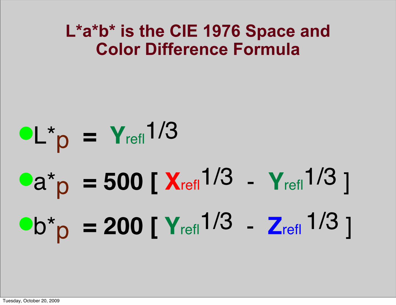
L*p = Yrefl1/3 a*p = 500 [ Xrefl1/3 - Yrefl1/3 ]b*p = 200 [ Yrefl1/3 - Zrefl 1/3 ]
L*a*b* is the CIE 1976 Space and Color Difference Formula
Tuesday, October 20, 2009

Lightness ?????Receptor PhysiologyResponse = Log (Intensity light)
Psychophysical ResultLightness = (Intensity light) 1/3
Scattered light in eyeball
Tuesday, October 20, 2009

Lightness = (Intensity light) 1/3
Retina = Log (Intensity light)
Tuesday, October 20, 2009

L*p = YreflAS a*p= 500 * [ XreflAS - YreflAS ]b*p= 200 * [ YreflAS - ZreflAS]
L*a*b* is the CIE 1976 Space and Color Difference Formula
Tuesday, October 20, 2009

L*a*b* / CIE 1976 Space and Color
Difference Formula
500 x Stretch
• LMS Cones
Tuesday, October 20, 2009
Tuesday, October 20, 2009

Summary• Scene• Scene dependent intraocular scatter (spatial)
• Limits HDR• Scene dependent appearance (spatial)• Best reproduction matches appearance
• Smaller color spaces prevent matching all pixels• Calculation intensive • Best done in Uniform Color Space (which one?)
• Practice• Reproduce Paintings (one room at a time)• Gamut Mapping (spatial - preseve edges)
Tuesday, October 20, 2009

Conservation
• Planet• Environment • Resources• Energy
Tuesday, October 20, 2009

Conservation
• Planet• Environment • Resources• Energy
• Fine art
Tuesday, October 20, 2009

Conservation • Planet
• Environment • Resources• Energy
• Fine art
• Edges in reproductions
Tuesday, October 20, 2009

[email protected]@[email protected]://web.mac.com/mccanns/McCannImaging/Home.html
Thank you
Tuesday, October 20, 2009