Embed Size (px)
Citation preview

Combo Roll Groover
WARNING!Read this Operator’s Manualcarefully before using thistool. Failure to understandand follow the contents ofthis manual may result inelectrical shock, fire and/orserious personal injury.
975 Manual
99 Washington Street Melrose, MA 02176 Phone 781-665-1400Toll Free 1-800-517-8431
Visit us at www.TestEquipmentDepot.com

Ridge Tool Company2
975 Combo Roll Groover
General Safety Rules
WARNINGRead and understand all instructions. Failure to follow allinstructions listed below may result in electric shock, fire,and/or serious personal injury.
SAVE THESE INSTRUCTIONS!
The term "power tool" in the warnings refers to yourmains-operated (corded) power tool or battery-operated(cordless) power tool.
Work Area Safety• Keep your work area clean and well lit. Cluttered or
dark areas invite accidents.
• Do not operate power tools in explosive atmo-spheres, such as in the presence of flam mableliquids, gases, or dust. Power tools create sparkswhich may ignite the dust or fumes.
• Keep children and by-standers away while oper-ating a power tool. Distractions can cause you to losecontrol.
• Keep floors dry and free of slippery materialssuch as oil. Slippery floors invite accidents.
• Guard or barricade the area when work piece ex -tends beyond machine. A guard or barricade thatprovides a minimum of three (3) feet clearance aroundthe work piece will reduce the risk of entanglement.
Electrical Safety
• Power tool plugs must match the outlet. Nevermodify the plug in any way. Do not use any adap -ter plugs with earthed (grounded) power tools.Un modified plugs and matching outlets will reducerisk of electric shock.
• Avoid body contact with earthed or grounded sur-faces such as pipes, radiators, ranges and refrig-erators. There is an increased risk of electrical shockif your body is earthed or grounded.
• Do not expose power tools to rain or wet condi-tions. Water entering a power tool will increase the riskof electrical shock.
Safety SymbolsIn this operator’s manual and on the product, safety symbols and signal words are used to communicate important safe-ty information. This section is provided to improve understanding of these signal words and symbols.
This is the safety alert symbol. It is used to alert you to potential personal injury hazards. Obey all safety messages that follow thissymbol to avoid possible injury or death.
DANGER indicates a hazardous situation which, if not avoided, will result in death or serious injury.
WARNING indicates a hazardous situation which, if not avoided, could result in death or serious injury.
CAUTION indicates a hazardous situation which, if not avoided, could result in minor or moderate injury.
NOTICE indicates information that relates to the protection of property.
This symbol means read the operator’s manual carefully before using the equipment. The operator’s manual containsimportant information on the safe and proper operation of the equipment.
This symbol means always wear safety glasses with side shields or goggles when handling or using this equipment to reducethe risk of eye injury.
This symbol indicates the risk of fingers and hands being crushed between the groove rolls.
This symbol indicates that a drill, impact tool, or other power tool should not be used to drive this device when used in place.
This symbol means always use a foot switch when using a threading machine/power drive.
This symbol means wear a hard hat when working overhead to reduce the risk of head injury.
This symbol indicates the risk of machine tipping, causing striking or crushing injuries.
This symbol indicates the risk of hands, fingers, legs, clothes and other objects catching and/or wrapping on rotating shaftscausing crushing or striking injuries.
NOTICE
DANGER
WARNING
CAUTION
Ridge Tool Company 3
• Do not abuse the cord. Never use the cord forcarrying, pulling or unplugging the power tool.Keep cord away from heat, oil, sharp edges ormoving parts. Damaged or entangled cords increasethe risk of electric shock.
• When operating a power tool outdoors, use anextension cord suitable for outdoor use. Use of acord suitable for outdoor use reduces the risk of elec-tric shock.
• If operating a power tool in a damp location isunavoidable, use a ground fault circuit interrupter(GFCI) protected supply. Use of an GFCI reduces therisk of electric shock.
Personal Safety
• Stay alert, watch what you are doing and use com-mon sense when operating a power tool. Do notuse a power tool while you are tired or under theinfluence of drugs, alcohol, or medication. Amoment of inattention while operating power toolsmay result in serious personal injury.
• Use personal protective equipment. Always weareye protection. Protective equipment such as dustmask, non-skid safety shoes, hard hat, or hearingprotection used for appropriate conditions will reducepersonal injuries.
• Prevent unintentional starting. Ensure the switchis in the off-position before connecting to powersource and/or battery pack, picking up or carryingthe tool. Carrying power tools with your finger on theswitch or energizing power tools that have the switchon invites accidents.
• Remove any adjusting key or wrench before turn-ing the power tool on. A wrench or a key left attachedto a rotating part of the power tool may result in per-sonal injury.
• Do not overreach. Keep proper footing and bal-ance at all times. This enables better control of thepower tool in unexpected situations.
• Dress properly. Do not wear loose clothing orjewelry. Keep your hair, clothing, and gloves awayfrom moving parts. Loose clothes, jewelry, or longhair can be caught in moving parts.
• If devices are provided for the connection of dustextraction and collection facilities, ensure these areconnected and properly used. Use of dust collectioncan reduce dust-related hazards.
975 Combo Roll Groover
Tool Use and Care• Do not force tool. Use the correct tool for your
application. The correct tool will do the job betterand safer at the rate for which it is designed.
• Do not use tool if the switch does not turn it ONand OFF. Any tool that cannot be controlled withthe switch is dangerous and must be repaired.
• Disconnect the plug from the power source and/orthe battery pack from the tool before making anyadjustments, changing accessories, or storingtools. Such preventive safety measures reduce the riskof starting the tool accidentally.
• Store idle tools out of the reach of children anddo not allow persons unfamiliar with the tool orthese instructions to operate the tool. Tools aredangerous in the hands of untrained users.
• Maintain tools. Check for misalignment or bindingof moving parts, breakage of parts and any othercondition that may affect the tool’s operation. Ifdamaged, have the tool repaired before use. Manyaccidents are caused by poorly maintained tools.
• Use only accessories that are recommended foryour tool. Properly maintained cutting tools with sharpcutting edges are less likely to bind and are easier tocontrol.
• Keep handles dry and clean; free from oil andgrease. Allows for better control of the tool.
Service
• Have your tool serviced by a qualified repair per-son using only identical replacement parts. This willensure that the safety of the tool is maintained.
Specific Safety Information
WARNINGThis section contains important safety informationthat is specific to this tool.
Read these precautions carefully before using the975 Combo Roll Groover to reduce the risk of seri-ous personal injury.
SAVE THESE INSTRUCTIONS!
caught in the machine and power is maintained tothe motor, the clothing will be pulled into the machine.This machine has high torque and can cause theclothing to bind around your arm or other body partswith enough force to crush or break bones or causestriking or other injuries.
• One person must control both the grooving pro-cess and the foot switch. Do not operate with morethan one person. In case of en tan g lement, the oper-ator must be in control of the foot switch.
• Only use power drives and threading machineswith a rotational speed of 57 rpm or less. Higherspeed machines increase the risk of injury.
• Be sure the roll groover is properly set up andsecured to the power drive/threading machine.Be sure the machine, stand, groover and pipe arestable. This will help prevent tipping of the equip-ment and pipe.
Roll Groover Safety When Used In Place• Only drive manually when used for in place appli-
cations. Do not use powered devices (such asdrills or impact tools) to drive the roll grooverwhen used in place. Use of powered devices candamage the Groove and increase the risk of injury.
• When working overhead, all personnel shouldwear hard hats and be clear of the area below.Prevents serious injuries if roll groover, pipe or otherobjects fall.
Description, Specifications andStandard EquipmentDescriptionThe RIDGID® 975 Combo Roll Groover forms rolledgrooves in steel, aluminum and PVC pipe and will groove11/4" to 6" diameter pipe, schedule 10 and schedule 40. Itis also designed to groove 11/4" to 6" schedule 10 and 11/4"to 2" schedule 40 stainless steel pipe. It can also beadapted for 2" - 8" Type K, L,M and DWV copper tube witha roll set change. The grooves are formed by mechanicallyadvancing a grooving roll into the pipe which is supportedby a drive roll. The only adjustment necessary is for thedepth of the groove.
The unit is specifically designed to be used either in placeor with the RIDGID Model 300 Power Drive (38 and 57RPM Models). With the appropriate adapter (cat. #67662),the unit can work with the RIDGID Model 300 CompactThreading Machine. The 975 Combo Roll Groov er includesa patented groove depth gauge to aid in groove set up andpatented features to improve tracking during use.
Roll Groover Safety• Do not wear loose clothing. Keep sleeves and
jackets buttoned. Do not reach across the machineor pipe. Clothing can be caught by the pipe or otherrotating parts, resulting in entanglement and seriousinjury.
• Keep hands away from grooving rolls. Do notgroove pipe shorter than specified. Do not wearloose fitting gloves. Fingers can be crushed betweengroove rolls or between groove roll and pipe.
• Keep hands away from ends of pipe. Do not reachinside pipe. Burrs and sharp edges can catch and cut.Fingers can be crushed between groove rolls orbetween groove roll and pipe.
• Properly prepare and handle pipe. Burrs and sharpedges can catch and cut.
• Properly support the pipe. This will help to preventthe tipping of the pipe and equipment.
• Read and understand this operator’s manual, theappropriate power drive or threading machineoperator’s manual, the fitting manufacturer’s instal-lation instructions and the in structions for anyother equipment used with this tool before oper-ating the RIDGID® 975 Combo Roll Groover. Failureto follow all instructions may result in property damageand/or serious personal injury.
• Always wear appropriate personal protective equip -ment while setting up and using the RIDGID 975Combo Roll Groover. Appropriate personal protectiveequipment always includes eye protection and mayinclude equipment such as tight fitting leather gloves,steel toed footwear, and a hardhat.
• Only use roll groover to groove pipe of recom-mended sizes and types according to these in -structions. Other uses or modifying the roll groover forother applications may increase the risk of injury.
Roll Groover Safety When Used With APower Drive/Threading Machine• Only use the RIDGID 300 Power Drive or the 300
Compact Threading Machine with this 975 ComboRoll Groover. Use of other power sources will result inimproper set up and could cause tipping or otherissues.
• Do not use this roll groover with a power drive orthreading machine that does not have a footswitch. Never block a foot switch so that it doesnot control the power drive. A foot switch providesbetter control by letting you shut off the power drivemotor by removing your foot. If clothing should become
Ridge Tool Company4
975 Combo Roll Groover
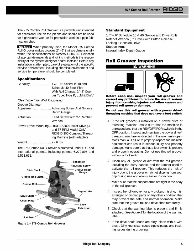
The 975 Combo Roll Groover is a portable unit intendedfor occasional use on the job site and should not be usedfor high volume work or for production work in a pipe fab-rication shop.
When properly used, the Model 975 ComboRoll Groover makes grooves 2" - 6" that are dimensionallywithin the specifications of AWWA C606-06. Selectionof appropriate materials and joining methods is the respon-sibility of the system designer and/or installer. Before anyinstallation is attempted, careful evaluation of the specificservice environment, including chemical environment andservice temperature, should be completed.
SpecificationsCapacity ........................11/4" – 6" Schedule 10 and
Schedule 40 Steel PipeWith Roll Change: 2"- 8" Cop -per Tube, Type K, L ,M & DWV
(See Table II for Wall Thickness)Groove DiameterAdjustment ....................Adjusting Screw And Groove
Depth Gauge
Actuation .......................Feed Screw with 1/2" RatchetWrench
Power Drive Mounting ...RIDGID 300 Power Drive (38and 57 RPM Model Only)RIDGID 300 Compact Thread -ing Machine (with adapter)
Weight............................27.6 lbs.
The 975 Combo Roll Groover is protected under U.S. andInternational patents, including patents 6,272,895 and6,591,652.
Figure 1 – 975 Combo Roll Groover
Standard Equipment11/4" – 6" Schedule 10 & 40 Groove and Drive RollsRatchet Wrench (1/2" Drive) with Button ReleaseLocking Extension DriveSupport ArmsIntegral Index Depth Gauge
Roll Groover InspectionWARNING
Before each use, inspect your roll groover andcorrect any problems to reduce the risk of seriousinjury from crushing injuries and other causes andprevent roll groover damage.
Do not use this roll groover with a power drive/ -thread ing machine that does not have a foot switch.
1. If the roll groover is installed on a power drive orthreading machine, make sure that the machine isunplugged and that the REV/OFF/FOR switch is in theOFF position. Inspect and maintain the power drive/ -thread ing machine as directed in the machine’s oper-ator’s manual. Failure to properly inspect and maintainequipment can result in serious injury and propertydamage. Make sure that that a foot switch is presentand properly operating. Do not use this roll grooverwithout a foot switch.
2. Clean any oil, grease or dirt from the roll groover,including the carry handle, and the ratchet used toactivate the roll groover. This reduces the risk ofinjury due to the groover or ratchet slipping from yourgrip during use and allows easier inspection.
3. Make sure that the support arms are tight in the bodyof the roll groover.
4. Inspect the roll groover for any broken, missing, mis-arranged or binding parts or any other condition thatmay prevent the safe and normal operation. Makesure that the groove roll and drive shaft turn freely.
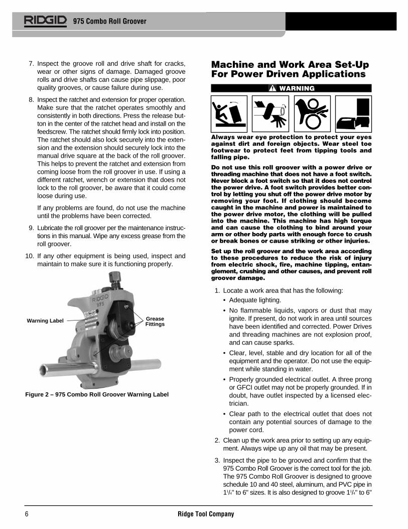
5. Check that the warning label is present and firmlyattached. See Figure 2 for the location of the warninglabel.
6. If the drive shaft knurls are dirty, clean with a wirebrush. Dirty knurls can cause pipe slippage and track-ing issues during grooving.
Ridge Tool Company 5
975 Combo Roll Groover
Groove Roll
Support Arm
Drive Shaft
Base
Feedscrew
Slide Block
Groove Roll Shaft
Groove DepthGauge
Extension
Ratchet
NOTICE
Adjusting Screw
Cover Plate
7. Inspect the groove roll and drive shaft for cracks,wear or other signs of damage. Damaged grooverolls and drive shafts can cause pipe slippage, poorquality grooves, or cause failure during use.
8. Inspect the ratchet and extension for proper operation.Make sure that the ratchet operates smoothly andconsistently in both directions. Press the release but-ton in the center of the ratchet head and install on thefeedscrew. The ratchet should firmly lock into position.The ratchet should also lock securely into the exten-sion and the extension should securely lock into themanual drive square at the back of the roll groover.This helps to prevent the ratchet and extension fromcoming loose from the roll groover in use. If using adifferent ratchet, wrench or extension that does notlock to the roll groover, be aware that it could comeloose during use.
If any problems are found, do not use the machineuntil the problems have been corrected.
9. Lubricate the roll groover per the maintenance instruc-tions in this manual. Wipe any excess grease from theroll groover.
10. If any other equipment is being used, inspect andmaintain to make sure it is functioning properly.
Figure 2 – 975 Combo Roll Groover Warning Label
Machine and Work Area Set-UpFor Power Driven Applications
WARNING
Always wear eye protection to protect your eyesagainst dirt and foreign objects. Wear steel toefootwear to protect feet from tipping tools andfalling pipe.
Do not use this roll groover with a power drive orthreading machine that does not have a foot switch.Never block a foot switch so that it does not controlthe power drive. A foot switch provides better con-trol by letting you shut off the power drive motor byremoving your foot. If clothing should becomecaught in the machine and power is maintained tothe power drive motor, the clothing will be pulledinto the machine. This ma chine has high torqueand can cause the clothing to bind around yourarm or other body parts with enough force to crushor break bones or cause striking or other injuries.
Set up the roll groover and the work area accordingto these procedures to reduce the risk of injuryfrom electric shock, fire, machine tipping, entan-glement, crushing and other causes, and prevent rollgroover damage.
1. Locate a work area that has the following:• Adequate lighting.
• No flammable liquids, vapors or dust that mayignite. If present, do not work in area until sourceshave been identified and corrected. Power Drivesand threading machines are not explosion proof,and can cause sparks.
• Clear, level, stable and dry location for all of theequipment and the operator. Do not use the equip-ment while standing in water.
• Properly grounded electrical outlet. A three prongor GFCI outlet may not be properly grounded. If indoubt, have outlet inspected by a licensed elec-trician.
• Clear path to the electrical outlet that does notcontain any potential sources of damage to thepower cord.
2. Clean up the work area prior to setting up any equip-ment. Always wipe up any oil that may be present.
3. Inspect the pipe to be grooved and confirm that the975 Combo Roll Groover is the correct tool for the job.The 975 Combo Roll Groover is designed to grooveschedule 10 and 40 steel, aluminum, and PVC pipe in11/4" to 6" sizes. It is also designed to groove 11/4" to 6"
Ridge Tool Company6
975 Combo Roll Groover
GreaseFittings
Warning Label

Ridge Tool Company 7
Figure 3 – Mounting 975 Combo Roll Groover Into 300Power Drive Chuck
Mounting The 975 Combo Groover Onto ARIDGID 300 Compact Threading MachineWhen using the 975 Combo Roll Groover with a 300Compact Threading Machine, an adapter kit (CatalogNumber 67662) must be used. This adapter kit properlypositions the 975 Combo Roll Groover relative to thethreading machine and stand and to allow the completerange of sizes to be grooved. Do not try to use the 975Combo Groover with any other threading machine, as tip-ping or other issues may result.
1. Install the drive bar adapter onto the roll grooverdrive shaft (See Figure 4). Align set screws with theflats on the roll groover drive shaft and firmly tighten.
Figure 4 – Installing Drive Bar Adapter
2. Move carriage on the 300 Compact Threading Ma -chine as close to the machine chuck as possible.Move the cutter, reamer and die head in to the posi-tion away from the operator, so they are out of theway. Position reamer cone inside of die head.
schedule 10 and 11/4" to 2" schedule 40 stainless steel pipe. With a roll set change, it can be used to groove 2" - 8" Type K, L, M and DWV copper tube.
The 975 Combo Roll Groover can be used for in place applications (pipe that is in place or mounted in a vise) or with a RIDGID 300 Power Drive or 300 Compact Threading Machine for power ed applications on the job site. The 975 Combo Roll Groover is not intended for production type applications.
Use of roll sets (groove roll and driveshaft)on both carbon and stainless steel pipe can lead to con-tamination of the stainless steel material. This contamina-tion could cause corrosion and premature pipe failure. Toprevent ferrous contamination of stainless steel pipe, use rollsets dedicated for stainless steel roll grooving. Alternately,a stainless steel wire brush may be used to thoroughlyclean the roll set when switching between materials.
4. Make sure the power drive/threading machine hasbeen inspected per it’s manual. Confirm the presenceof a foot switch and make sure that the FOR/ OFF/ -REV switch is in the OFF position. Set up the powerdrive/threading machine as directed in it’s manual.Make sure that the machine and stand are stable anddo not wobble.
5. Fully open the chuck of the power drive/threadingmachine.
6. Confirm that the 975 Combo Roll Groover has beeninspected and has the appropriate roll set installed.
Mounting The 975 Combo Groover OntoA RIDGID 300 Power Drive1. If the power drive to be used is equipped with a car-
riage or other attachments, remove them from thepower drive. Make sure the power drive supportarms are fully forward and fixed in position.
2. Place the support arms of the roll groover onto thesupport arms of the power drive and the end of the rollgroover driveshaft in the chuck of the machine. Closeand tighten the power drive chuck onto the flats of thedriveshaft. Make sure that the driveshaft is centeredin the chuck. Use repeated and forceful counter-clockwise spins of the speed chuck hammerwheel tosecurely grip the driveshaft (Figure 3).
975 Combo Roll Groover
NOTICE
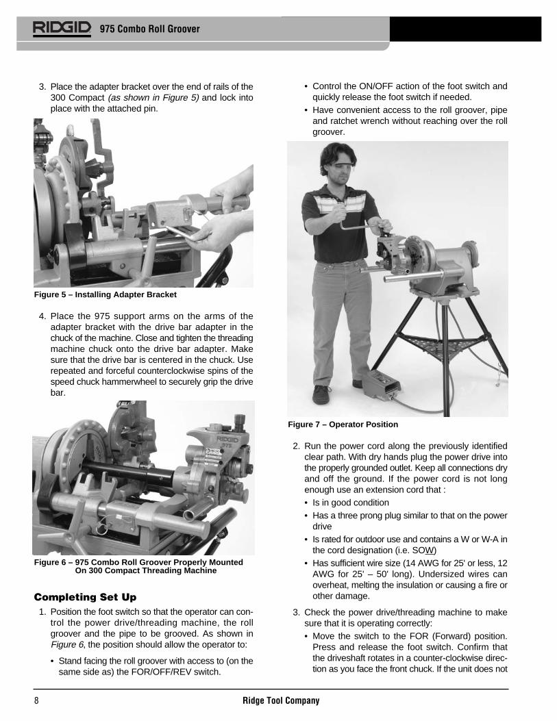
3. Place the adapter bracket over the end of rails of the300 Compact (as shown in Figure 5) and lock intoplace with the attached pin.
Figure 5 – Installing Adapter Bracket
4. Place the 975 support arms on the arms of theadapter bracket with the drive bar adapter in thechuck of the machine. Close and tighten the threadingmachine chuck onto the drive bar adapter. Makesure that the drive bar is centered in the chuck. Userepeated and forceful counterclockwise spins of thespeed chuck hammerwheel to securely grip the drivebar.
Figure 6 – 975 Combo Roll Groover Properly MountedOn 300 Compact Threading Machine
Completing Set Up1. Position the foot switch so that the operator can con-
trol the power drive/threading machine, the rollgroover and the pipe to be grooved. As shown inFigure 6, the position should allow the operator to:
• Stand facing the roll groover with access to (on thesame side as) the FOR/OFF/REV switch.
• Control the ON/OFF action of the foot switch andquickly release the foot switch if needed.
• Have convenient access to the roll groover, pipeand ratchet wrench without reaching over the rollgroover.
Figure 7 – Operator Position
2. Run the power cord along the previously identifiedclear path. With dry hands plug the power drive intothe properly grounded outlet. Keep all connections dryand off the ground. If the power cord is not longenough use an extension cord that :• Is in good condition• Has a three prong plug similar to that on the power
drive• Is rated for outdoor use and contains a W or W-A in
the cord designation (i.e. SOW)• Has sufficient wire size (14 AWG for 25' or less, 12
AWG for 25' – 50' long). Under sized wires canoverheat, melting the insulation or causing a fire orother damage.
3. Check the power drive/threading machine to makesure that it is operating correctly:• Move the switch to the FOR (Forward) position.
Press and release the foot switch. Confirm thatthe driveshaft rotates in a counter-clockwise direc-tion as you face the front chuck. If the unit does not
Ridge Tool Company8
975 Combo Roll Groover

2. Make sure to have appropriate support available forthe pipe you are going to be grooving. Chart A liststhe maximum length of pipe to be grooved using asingle pipe stand. Longer lengths of pipe should besupported with at least two pipe stands. Failure toproperly support the pipe may allow the pipe or thepipe and machine to tip and fall. Do not groove pipeshorter than the minimum length.
3. Place the required pipe stands in front of the rollgroover. For lengths supported by a single stand, thestand should be placed slightly more than half thelength of the pipe from the roll groover cover plate. Forlengths of pipe requiring more than one stand, thestands should be placed 1/4 of the pipe length from theends of the pipe. It may be appropriate to use morestands in some situations. Stand height should beadjusted so that the pipe can fit over the drive roll.
4. Make sure that the groove roll has been retractedenough to allow the pipe to be placed over the driveshaft. If needed, turn the feedscrew counter-clockwiseto raise the groove roll.
5. Place the pipe end over the driveshaft and set thepipe down onto the pipe stand(s). Make sure thepipe is stable.
Figure 8 – Placing Pipe Over Driveshaft and Flush ToCover Plate
6. Adjust pipe and pipe stands so that the end of thepipe is flush to the roll groover cover plate and that theinside of the pipe contacts the top of the driveshaft
rotate in the correct direction or the foot switch doesnot control the machine operation, do not use themachine until it has been repaired.• Depress and hold the foot switch. Check the rota-
tional speed of the unit. Inspect the moving parts formisalignment, binding, odd noises or any otherunusual conditions. Release foot switch. If the rota-tional speed exceeds 57 rpm, do not use the unit forroll grooving. Higher speeds may increase the riskof injury. If unusual conditions are found, do not usethe equipment until it has been repaired.
• Move the switch to the REV (reverse) position.Press and release the foot switch. Con firm thatthe driveshaft rotates in a clockwise direction as youface the front of the chuck. If the unit does notrotate in the correct direction, do not use themachine until it has been repaired.
• Move the switch to the OFF position. With dryhands unplug the machine.
Pipe PreparationThese are generalized instructions. Always
follow grooved coupling manufacturer’s specific recom-mendations for pipe end preparation. Failure to follow thegrooved coupling manufacturer’s recommendations maylead to an improper connection and cause leaks.
1. Cut pipe to proper length. Be aware of the minimumlengths of pipe that can be grooved for each size ofpipe (See Chart A). Grooving pipe shorter than min-imum length increases the risk of injury from crushedfingers and entanglement.
Make sure pipe end is cut square and free of burrs.Burrs can catch or cut gloves or fingers during groov-ing. Cut off method and large burrs can effect thequality of the groove made and the tracking of theGroove. Do not attempt to groove pipe that has beencut with a torch.
2. All internal/external weld beads, flash, or seams mustbe ground flush at least 2" back from the end of thepipe. Do not cut flats into gasket seat area, this couldcause leaks.
3. Remove all scale, dirt, rust and other contaminants atleast 2" back from the end of the pipe. Contaminantscan clog the drive knurls and prevent proper drivingand tracking of the pipe while grooving.
Pipe Set Up In Roll Groover 1. Confirm that the power drive switch/threading ma -
chine is in the OFF position.
Ridge Tool Company 9
975 Combo Roll Groover
Nom. Min. Max. Nom. Min. Max.Size Length Length Size Length Length
1 8 36 4 8 3611/4 8 36 41/2 8 3211/2 8 36 5 8 322 8 36 6 O.D. 10 30
21/2 8 36 6 10 283 8 36
31/2 8 36
Chart A – Minimum/Maximum Pipe Length To Be GroovedWith One Stand (All Dimensions In Inches)
NOTICE
Cover Plate

(Figure 7). The centerline of the pipe and the cen-terline of the drive shaft should be parallel to oneanother. One way to do this is to level both the pipeand the power drive/threading machine.
7. Slightly offset the pipe and pipe stands approximately1/2 degree (about 1" over at 10 feet from the roll groo -v er) towards the operator. Proper alignment of thepipe and roll groover helps to insure proper trackingof the pipe while grooving. (See Figure 9.)
Figure 9 – Offsetting The Pipe 1/2° Towards Operator(Exaggerated)
8. Turn the feedscrew clockwise to bring the grooveroll down in contact with the pipe outside diameter,then turn the feedscrew one quarter additional turn.The adjusting screw may need to be loosened (turnedcounter-clockwise) to allow the groove roll to contactpipe. The pipe and roll groover should be secure toeach other at this point.
9. Evaluate the work area and determine if any barriersare required to keep people other than the operator
Ridge Tool Company10
975 Combo Roll Groover
away from the equipment and pipe. Guards or barri-cades should be used to create a minimum of three(3) feet of clearance around the power drive andpipe. This “safety zone” prevents others from acci-dentally contacting the machine or pipe and causingtipping or becoming entangled in the rotating parts.
10. With dry hands, plug the machine into the properlygrounded outlet.
Operating The 975 Combo RollGroover With A PowerDrive/Threading Machine
WARNING
Do not wear loose clothing when operating the rollgroover. Keep sleeves and jackets buttoned. Donot reach across the machine or pipe. Loose cloth-ing can become entangled in rotating parts andcause crushing injuries.
Keep hands away from grooving rolls. Do not groovepipes shorter than specified. Do not wear loosefitting gloves. Fingers can be crushed betweengroove rolls or between groove roll and pipe.
Keep hands away from ends of pipe. Do not reachinside pipe. Burrs and sharp edges can catch andcut. Fingers can be crushed between groove rolls orbetween groove roll and pipe.
Always wear eye protection to protect your eyesagainst dirt and foreign objects. Wear steel toefootwear to protect feet from tipping tools andfalling pipe.
Follow operating instructions to reduce the risk ofinjury from crushing, tipping, striking and othercauses.
Setting/Measuring The Groove DiameterDue to differing pipe characteristics, a test
groove should always be performed before the firstgroove of the day or when changing pipe size, scheduleor material. Groove diameter setting gauges are approx-imate only and the groove diameter must be measuredto confirm proper size.
1. Confirm that the equipment and pipe is properly setup. Improper pipe preparation can effect the accurateset up of the groove depth gauge. The groove rollshould be touching the pipe.
2. Adjust the groove depth gauge so that the correctstep of the gauge is under the head of the adjustingscrew (Figure 10A). The groove depth gauge is
NOTICE
Drive ShaftCenter Line
PipeCenterLine
1/2°

designed for use with pipe. See “Setting The GrooveDiameter For Copper Tube” for use with copper tube.
3. Turn the adjusting screw clockwise until the headtouches the step of the depth gauge. Turn the groovedepth gauge to the grooving position (Figure 10B). Ifthe gauge is not in the grooving position it will preventgrooving and may be damaged.
4. Prepare a test groove (follow the steps for “Formingthe Roll Groove).
5. Measure the groove diameter. The best method formeasuring groove diameter is the use of a diametertape (see Accessories Section). Snugly wrap thediameter tape around the pipe in the groove. Makesure that the tape sits flat in the bottom of the groove,and read the groove diameter. (See Figure 11.)
Figure 11 – Checking Groove Diameter With A DiameterTape
6. Compare the measured groove diameter to the re -quired groove diameter as shown in Table I or III or asspecified by the groove fitting manufacturer. If themeasured groove is outside of the required groove
Ridge Tool Company 11
975 Combo Roll Groover
diameter, the adjusting screw must be repositioned togive the correct groove diameter.
• To increase groove diameter, turn the adjustingscrew clockwise.
• To decrease groove diameter, turn the adjustingscrew counter-clockwise.
• Each 1/4 turn of the adjusting screw changes thegroove diameter approximately 0.02".
7. Repeat steps 4-6 until the groove diameter is withinspecifications. If the groove is too large, the groovercan be adjusted and the groove made smaller. If thegroove is too small, another groove will need to bemade. Proper groove diameter is important to insureconnection performance. Out of specification groovescould cause joint failure.
Forming The Roll Groove1. Confirm that the equipment and pipe are properly
set up.
Figure 12 – Roll Groover Operating Position
2. Assume a proper operating position. Position thepower drive foot switch so that the operator can con-trol the power drive, the roll groover and the pipe to begrooved. As shown in Figure 12, the position shouldallow the operator to:
Figure 10B – Gauge InGrooving Position
Figure 10A – Place CorrectStep of Gauge UnderAdjusting Screw Head
• Stand facing the roll groover with access to (onthe same side as) the FOR/OFF/REV switch.
• Control the ON/OFF action of the foot switch andquickly release the foot switch if needed.
• Have convenient access to the groover and ratch-et wrench without reaching over the roll groover.
• Place right hand on pipe being grooved if needed.• Have good footing and proper balance.
3. Move the FOR/OFF/REV switch to the REV (reverseposition). Do not run the 975 Combo Roll Groov erin the FOR (forward). Because of the design of the975 Combo Roll Groover, this will cause the pipeto “spiral” out of the roll groove rolls and mayallow the pipe to fall.
4. Place one hand on the on the head of the ratch-et/top of the feedscrew and the other hand on the endof the ratchet.
5. Press the foot switch to start the power drive. Watchthe pipe rotate and be sure that the face of the pipestays in contact with the cover plate of the roll groover.If the pipe starts to move away from the roll groovercover plate, release the foot switch to prevent the pipefrom spiraling off and falling. If needed, re-set up thepipe (see Pipe Set Up Section). If the pipe end is de -formed, it will need to be cut off and a new grooveprepared.
6. As the pipe completes a full rotation, tighten the feed-screw another 1/4 turn. Continue to monitor the pipeend to make sure that it is in contact with the coverplate. Do not tighten the feedscrew more than 1/4
turn per pipe rotation. Aggressive tightening of thefeedscrew can cause excessive groove flare or causethe pipe to spiral off the drive shaft.
7. Continue tightening the feedscrew 1/4 turn per pipe rev-olution until the head of the adjusting screw stopsagainst the top of the roll groover. Do not continuetightening the feedscrew after the adjusting screwreaches the top of the roll groover, this can damagethe adjusting screw. Allow the pipe to rotate at leasttwo more full rotations in this position to insure uniformgroove depth.
8. Release the foot switch and move the FOR/OFF/REVswitch to the OFF position.
9. Turn the feedscrew counter-clockwise and raise thegroove roll so that the pipe can be removed fromthe machine.
10. Inspect the groove.• Make sure that the groove is fully formed.
• Check the groove diameter and make sure it iswithin specification.
• Check any other items required by the fitting man-ufacturer.
If any problems are found, the groove cannot be used.
Setting The Groove Diameter ForCopper TubingWhen using the 975 Combo Roll Groover for coppertube, the groove depth gauge on the groover cannot beused. It will give incorrect groove diameters.
1. Turn the feedscrew clockwise to bring the grooveroll down in contact with the pipe outside diameter,then turn the feedscrew one quarter additional turn.The adjusting screw may need to be loosened (turnedcounter-clockwise) to allow the groove roll to contactpipe. The pipe and roll groover should be secure toeach other at this point.
2. Make sure the groove depth gauge is in the groovingposition. (Figure 10B)
3. Turn the adjusting screw until it is flush with the topplate of the groover.
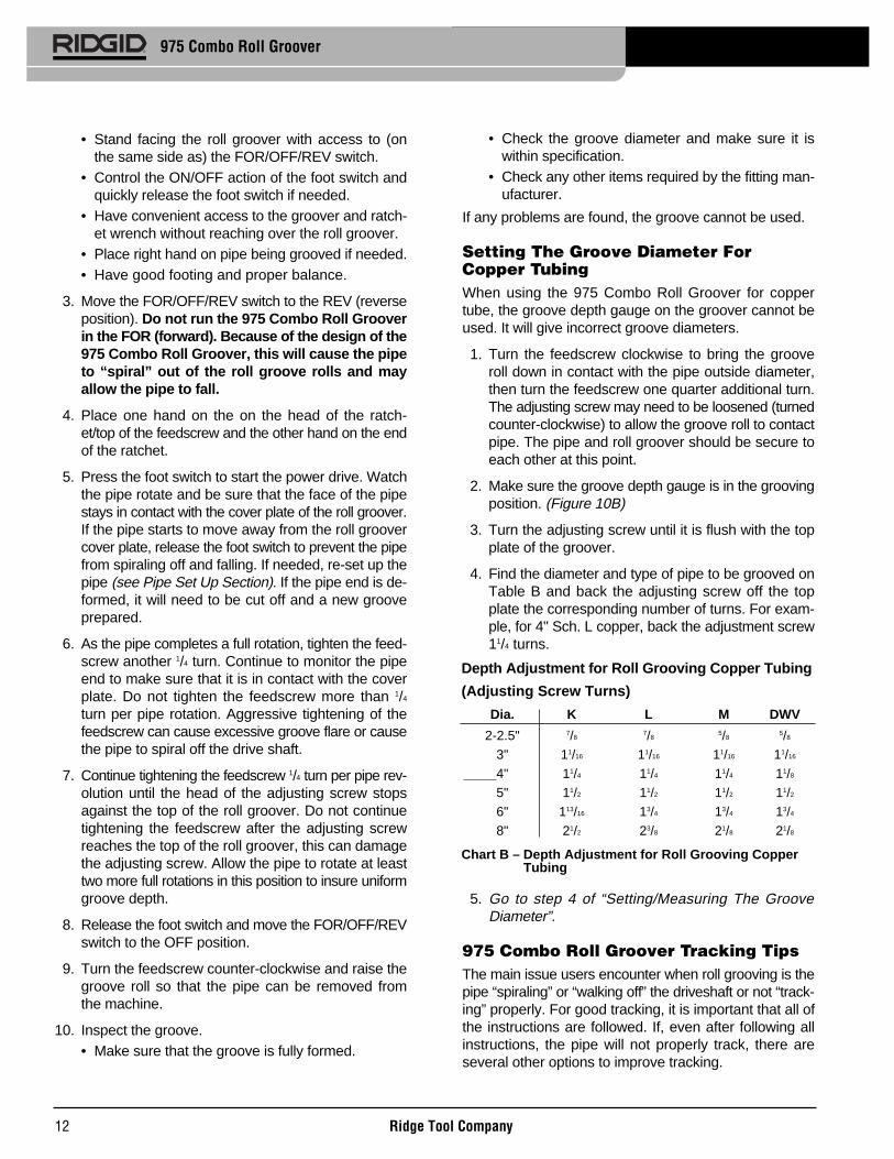
4. Find the diameter and type of pipe to be grooved onTable B and back the adjusting screw off the topplate the corresponding number of turns. For exam-ple, for 4" Sch. L copper, back the adjustment screw11/4 turns.
5. Go to step 4 of “Setting/Measuring The GrooveDiameter”.
975 Combo Roll Groover Tracking TipsThe main issue users encounter when roll grooving is thepipe “spiraling” or “walking off” the driveshaft or not “track-ing” properly. For good tracking, it is important that all ofthe instructions are followed. If, even after following allinstructions, the pipe will not properly track, there areseveral other options to improve tracking.
Ridge Tool Company12
975 Combo Roll Groover
Chart B – Depth Adjustment for Roll Grooving CopperTubing
Depth Adjustment for Roll Grooving Copper Tubing
(Adjusting Screw Turns)
Dia. K L M DWV
2-2.5" 7/87/8
5/85/8
3" 11/16 11/16 11/16 11/16
4" 11/4 11/4 11/4 11/8
5" 11/2 11/2 11/2 11/2
6" 113/16 13/4 13/4 13/4
8" 21/2 23/8 21/8 21/8

Ridge Tool Company 13
975 Combo Roll Groover
• Slightly increase the offset of the pipe towards theoperator (increase from 1/2 degree to 1 degree) (SeeFigure 9).
• The operator may need to apply slight force on thepipe while grooving to maintain tracking. This is usu-ally only needed on shorter sections of pipe. To dothis, the operator should wear a leather glove ingood condition and cup their hand around the middleof the pipe as shown in Figure 13. This may requirethat the stand to which the power drive/threadingmachine is mounted be fixed to the floor to preventmovement during grooving. To prevent crushinginjuries, keep hand away from the groove roll and theends of the pipe, and do not groove pipe shorterthat recommended.
Figure 13 – Applying Force To Pipe While Grooving ToMaintain Tracking
• Additionally, see the Troubleshooting Section for acomplete list of reasons for and solutions to trackingissues.
Machine and Work Area Set-UpFor In Place Applications
WARNING
Always wear eye protection to protect your eyesagainst dirt and foreign objects. Wear steel toefootwear to protect feet from tipping and fallingpipe and tools. When working in place, wear a hardhat.
Set up roll groover and work area according tothese procedures to reduce the risk of injury frommachine tipping, crushing and other causes, andprevent roll groover damage.
1. Locate a work area that has the following:
• Adequate lighting.
• No flammable liquids, vapors or dust that may ignite.If present, do not work in area until sources havebeen identified and corrected.
• Clear, level, stable and dry location with adequatespace for all of the equipment and the operator.
2. Clean up the work area prior to setting up any equip-ment. Always wipe up any oil that may be present.
3. Inspect the pipe to be grooved and confirm that the975 Combo Roll Groover is the correct tool for the job.The 975 Combo Roll Groover is designed to grooveschedule 10 and 40 steel, aluminum, and PVC pipe in11/4" to 6" sizes. It is also designed to groove 11/4" to 6"schedule 10 and 11/4" to 2" schedule 40 stainlesssteel pipe. With a roll set change, it can be used togroove 2" - 8" Type K, L, M and DWV copper tube.
The 975 Combo Roll Groover can be used for inplace applications (pipe that is in place or mounted ina vise) or with a RIDGID 300 Power Drive or 300Compact Threading Machine for power ed applicationson the job site. The 975 Combo Roll Groover is notintended for production type applications.
4. When grooving in place, make sure that there will beenough space for the 975 Combo Roll Groover to fitand be operated. The roll groover will orbit around thesolidly mounted pipe and requires:• A minimum of 61/2" clear space around the pipe to
the be grooved• A minimum of 21/2" pipe extending past an obstruc-
tion such as a wall

Ridge Tool Company14
975 Combo Roll Groover
• A minimum opening of 91/2" to fit the roll grooveronto the pipe
Use of roll sets (groove roll and driveshaft) onboth carbon and stainless steel pipe can lead to con-tamination of the stainless steel material. This contami-nation could cause corrosion and premature pipe failure.To prevent ferrous contamination of stainless steel pipe,use roll sets dedicated for stainless steel roll grooving.Alternately, a stainless steel wire brush may be used tothoroughly clean the roll set when switching betweenmaterials.
Pipe PreparationThese are generalized instructions. Always
follow grooved coupling manufacturer’s specific recom-mendations for pipe end preparation. Failure to followthe grooved coupling manufacturer’s recommendationsmay lead to an improper connection and cause leaks.
1. If grooving in place on an existing piping, make surethat the system has been depressurized and emptiedof contents. Know what the contents are and anyhazards associated with them.
2. Cut pipe to proper length.
Make sure pipe end is cut square and free of burrs.Burrs can catch or cut gloves or fingers during groov-ing. Cut off method and large burrs can effect thequality of the groove made and the tracking of theGroove. Do not attempt to groove pipe that has beencut with a torch.
3. All internal/external weld beads, flash, or seams mustbe ground flush at least 2" back from the end of thepipe. Do not cut flats into gasket seat area, this couldcause leaks.
4. Remove all scale, dirt, rust and other contaminants atleast 2" back from the end of the pipe. Contaminantscan clog the drive knurls and prevent proper drivingand tracking of the pipe while grooving.
5. Make sure that the pipe to be grooved is solidlymounted. The pipe must be able to withstand theweight of the roll groover (28 pounds), and the forceand torque required for grooving without moving.For pipe that is in place, it may make sense to re movethe pipe and groove at a pipe vise. In other cases, itmay be necessary to add other temporary or perma-nent pipe supports. When using a pipe vise, makesure that it is secure and will not tip during use. Forlonger lengths of pipe, use appropriate pipe stands tosupport the extra length.
Mounting The Roll Groover To The Pipe1. Confirm that the 975 Combo Roll Groover has been
inspected and has the appropriate roll set installed.Make sure that the support arms are tight in the bodyof the roll groover or remove them completely forbetter access in tight spaces. Next, install the ratchetinto the feedscrew and install the extension into themanual drive square at the back of the roll groover.Make sure both the ratchet and extension are secure-ly installed.
2. Make sure that there is enough space between thegroove roll and drive shaft for the pipe wall. If needed,turn the feedscrew counter-clockwise to retract thegroove roll.
3. Securely grasp the roll groover. Do not lift with theratchet. Place the driveshaft into the pipe and makesure that the cover plate is tight to the end of the pipe(Figure 14). Tighten the feedscrew to bring the grooveroll into contact with the outside of the pipe. Once thefeedscrew is hand tight, use the ratchet to tighten thefeedscrew an additional 1/4 turn. Confirm that the rollgroover is securely attached to the pipe and thecover plate is flush to the end of the pipe. If not,repeat procedure. Always make sure groover issecure when used in place to prevent it from falling.
Figure 14 – Holding the Roll Groover In Place WhileTightening the Feedscrew
NOTICE
NOTICE
Cover Plate

Ridge Tool Company 15
975 Combo Roll Groover
Operating The 975 Combo RollGroover In Place
WARNING
Only drive manually when used for in place appli-cations. Do not use powered devices (such as drillsor impact tools) to drive the roll groover when usedin place. Use of powered devices can damage thegroover and increase the risk of injury.
Do not wear loose clothing when operating the rollgroover. Keep sleeves and jackets buttoned. Donot reach across the machine or pipe. Loose cloth-ing can become entangled in rotating parts andcause crushing injuries.
Keep hands away from grooving rolls. Do not groovepipes shorter than specified. Do not wear loose fit-ting gloves. Fingers can be crushed between grooverolls or between groove roll and pipe.
Keep hands away from ends of pipe. Do not reachinside pipe. Burrs and sharp edges can catch andcut. Fingers can be crushed between groove rolls orbetween groove roll and pipe.
Always wear eye protection to protect your eyesagainst dirt and foreign objects. Wear steel toe foot -wear to protect feet from tipping tools and fallingpipe. When working in place, wear a hard hat.
Follow operating instructions to reduce the risk ofinjury from crushing, tipping, striking and othercauses.
Setting/Measuring The Groove DiameterDue to differing pipe characteristics, a test
groove should always be performed before the firstgroove of the day or when changing pipe size, scheduleor material. Groove diameter setting gauges are approx-imate only and the groove diameter must be measured toconfirm proper size.
1. Confirm that the equipment and pipe are properlyset up. Improper pipe preparation can effect theaccurate set up of the groove depth gauge. Thegroove roll should be touching the pipe.
2. Adjust the groove depth gauge so that the correct stepof the gauge is under the head of the adjusting screw(Figure 15A). The groove depth gauge is designed foruse with pipe. See “Setting The Groove Diameter ForCopper Tube” for use with copper tube.
3. Turn the adjusting screw clockwise until the head
touches the step of the depth gauge. Turn the groovedepth gauge to the grooving position (Figure 15B). Ifgauge is not in the grooving position it will preventgrooving and may be damaged.
4. Prepare a test groove (follow the steps for “Formingthe Roll Groove).
5. Measure the groove diameter. The best method formeasuring groove diameter is the use of a diametertape (See Accessories Section). Snugly wrap thediameter tape around the pipe in the groove. Makesure that the tape sits flat in the bottom of the groove,and read the groove diameter (See Figure 16).
Figure 16 – Measuring The Groove Diameter With ADiameter Tape
6. Compare the measured groove diameter to the re -quired groove diameter as shown in Table I or III or asspecified by the groove fitting manufacturer. If themea sured groove is outside of the required groovediameter, the adjusting screw must be repositioned togive the correct groove diameter.• To increase groove diameter, turn the adjusting
screw clockwise.
Figure 15B – Gauge InGrooving Position
Figure 15A – Place CorrectStep of Gauge UnderAdjusting Screw Head
NOTICE

Ridge Tool Company16
975 Combo Roll Groover
• To decrease groove diameter, turn the adjustingscrew counter-clockwise.
• Each 1/4 turn of the adjusting screw changes thegroove diameter approximately 0.02".
7. Repeat steps 4-6 until the groove diameter is withinspecifications. If the first groove is too large, theGroove can be adjusted and the groove made small-er. If the groove is too small, another groove willneed to be made. Proper groove diameter is importantto insure connection performance. Out of specificationgrooves could cause joint failure.
Forming The Roll Groove1. Confirm that the equipment and pipe are properly
set up.
2. Assume a proper operating position. Make sure thatyour footing is good and you are well balanced.
3. Make sure that the feedscrew has been tightened 1/4
turn.
4. Remove the ratchet from the feedscrew and secure-ly install in the extension. (In close quarters applica-tions, the extension does not need to be used.)
5. Turn the ratchet clockwise as viewed from the back ofthe roll groover (this will match the arrows cast into theback of the roll groover, see Figure 17). Watch thegroover rotate and be sure that the cover plate of theroll groover stays in contact with the end of the pipe.If the roll groover starts to move away from the pipeend, stop rotating the ratchet to prevent the rollgroover from spiraling off the pipe end and falling.The roll groover support arms can be pushed on tohelp bring the cover plate back in contact with the pipeend. If needed, re-mount the roll groover to the pipe.(see “Mounting Roll Groover to Pipe” section). If thepipe end is deformed, it will need to be cut off and anew groove prepared.
Figure 17 – Turning the Ratchet in the Direction of theArrows
6. Continue rotating the ratchet until the roll groovercompletes at least a full rotation around the pipe.Remove the ratchet from the extension and attach tothe feedscrew. Tighten the feedscrew another 1/4
turn. Remove the ratchet from the feedscrew andsecurely attach to the extension. Do not tighten thefeedscrew more than 1/4 turn per pipe rotation. Ag -gressive tightening of the feedscrew can cause exces-sive groove flare and can cause the roll groover towalk off the pipe. Continue rotating the ratchet todrive the roll groover around the pipe while monitoringthe position of the cover plate to the end of the pipe.
7. Continue tightening the feedscrew 1/4 turn per grooverevolution around pipe until the head of the adjustingscrew stops against the top of the roll groover. Do notcontinue tightening the feedscrew after the adjustingscrew reaches the top of the roll groover, this candamage the adjusting screw. Rotate the roll grooverat least two more full rotations around the pipe afterthe adjusting screw reaches the top of the roll grooverto insure uniform groove depth.
8. Move the ratchet to the feedscrew. Securely grasp theroll groover. Turn the feedscrew counter-clockwiseand retract the groove roll so that the roll groover canbe removed from the pipe. Do not drop the rollgroover.
9. Inspect the groove.• Make sure that the groove is fully formed.• Check the groove diameter and make sure it is
within specification.• Check any other items required by the fitting man-
ufacturer.
If any problems are found, the groove cannot be used.
Maintenance InstructionsWARNING
Make sure the power drive switch is in the OFFpo sition and the unplugged before performing anymaintenance or making any adjustments.
LubricationLubricate the 975 Combo Roll Groover with a good gen-eral purpose grease once a month.
• Grease fittings are located on the side of the oper-ator’s side of the base, the front of the slide block,and the end of the groove roll shaft (See Figure 2).Add grease until a small amount is pushed out.
• Apply a light coat of grease to the feedscrew.Turn

Figure 19 – Removing Retaining Ring
6. Remove key and then thrust washer.
7. Slide thrust washer onto new driveshaft.
8. Insert key and install gear.
9. Install retaining ring into driveshaft groove.
10. Place driveshaft assembly into main housing.
11. Grease from the gearbox may have been lost duringthe driveshaft change. Make sure the bearings andgear teeth are coated sufficiently with a good gener-al purpose grease.
12. Insert pinion and reinstall rear cover. Tighten screwsto 12-16 ft*lbs of torque.
Figure 20 – 975 Combo Roll Groover Parts Diagram
Removing and Installing Groove Roll
1. Remove the setscrew that holds the groove roll shaftin place.
2. Pull the groove roll shaft out of the slide block andremove the groove roll and thrust washer.
3. Insert the thrust washer and new groove roll into theslide block. Ensure that the internal retaining ring inthe groove roll is closest to the main housing, and thatthe groove roll is between the thrust washer andmain housing.
• The gear box of the 975 Combo Roll Groover isgreased for life and does not require the addition ofany grease unless the gear box is opened.
See Inspection Section for other information on mainte-nance.
CleaningClean the driveshaft knurls with a wire brush on a dailybasis or more often if needed.
Changing Roll SetsWhen changing roll set parts, always make
sure drive and groove roll markings match. Mismatchedparts can make improper grooves and cause leaks.
Remove the roll groover from the power drive or thread-ing machine and place on a stable work bench.
Required Tools:• 3/8" Hex Wrench• 3/32" Hex Wrench• .070" External Retaining Ring Pliers
Removing and Installing Drive Roll
1. Remove 6 screws that hold rear cover to the hous-ing.
2. Remove the rear cover (See Figure 18).
Figure 18 – Removing Rear Cover
3. Remove pinion.
4. Remove the driveshaft assembly out of the back ofthe 975 Roll Groover.
5. Remove retaining ring from driveshaft and slide gearoff. (See Figure 19.)
Ridge Tool Company 17
975 Combo Roll Groover
NOTICE
Gear
ThrustWasher
Retaining Ring
Main Housing
Pinion
Driveshaft Rear CoverGear
ScrewsRetainingRing
ThrustWasher
Key
Rear Cover

Figure 21
4. Replace the groove roll shaft and the set screw.
5. Visually inspect the alignment between the groove rolland the drive roll. If they are not aligned, check ori-entation of groove roll and thrust washer.
6. Grease as directed in Lubrication Section of manual.
Accessories
WARNINGThe following RIDGID products have been designedto function with the 975 Combo Roll Groover. Otheraccessories suitable for use with other tools may behazardous when used on the 975 Combo RollGroover. To reduce the risk of serious injury, onlyuse accessories specifically designed and recom-mended for use with the 975 Combo Roll Groover,such as those listed in the chart.
Ridge Tool Company18
975 Combo Roll Groover
Machine StorageWARNING Store the tool in a locked area that is
out of reach of children and people unfamiliar with roll groover equipment. This tool can cause serious injury in the hands of untrained users.
Service and RepairWARNING
Improper service or repair can make machine unsafe to operate.
The “Maintenance Instructions” will take care of most of the service needs of this machine. Any problems not addressed by this section should only be handled by an authorized RIDGID service technician.
Tool should be taken to a RIDGID Independent Author -ized Service Center or returned to the factory.
When servicing this machine, only identical replacement parts should be used. Use of other parts may create a risk of serious injury.
Cat. Number Description41855 300 Power Drive, 115V 25-60Hz 38RPM75075 300 Power Drive, 115V 23-60Hz 57RPM42360 1206 Stand for 300 Power Drive66947 300 Compact, 115V 50/60Hz 38RPM73447 300 Compact, 115V 50/60Hz 52RPM67662 Adapter Bracket for 300 Compact67657 250 Folding Wheel Stand for 300 Compact72037 460 Portable TRISTAND Chain Vise56662 VJ-99 VHead High Pipe Stand76822 Inch Diameter Tape76827 Metric Diameter Tape30708 Extension, 1/2" Drive, Locking30703 Ratchet, 1/2" Drive With 90° bend32833 Groove and Drive Rolls for 2" - 8" Copper
Tube Type K, L, M and DWV
Main Housing
Set Screw
ThrustWasher
GrooveRoll
SlideBlock

Ridge Tool Company 19
975 Combo Roll Groover
Table I. Standard Roll Groove Specifications For Pipe of IPS DimensionsNOTE! All Dimensions are in Inches.
T A B C DNOM. PIPE MIN. GASKET GROOVE GROOVE NOM.PIPE DIAMETER WALL SEAT WIDTH DIAMETER GROOVESIZE O.D. TOL. THK. +.015/-.030 +.030/-.015 O.D. TOL. DEPTH (Ref.) (2)
11/4 1.660 +.016 .065 .625 .344 1.535 +.000 .063-.016 -.015
11/2 1.900 +.016 .065 .625 .344 1.775 +.000 .063-.016 -.015
2(1) 2.375 +.024 .065 .625 .344 2.250 +.000 .063-.016 -.015
21/2(1) 2.875 +.029 .083 .625 .344 2.720 +.000 .078
-.016 -.0153(1) 3.50 +.030 .083 .625 .344 3.344 +.000 .078
-.018 -.01531/2
(1) 4.00 +030 .083 .625 .344 3.834 +.000 .083-.018 -.015
4(1) 4.50 +.035 .083 .625 .344 4.334 +.000 .083-.020 -.015
5(1) 5.563 +.056 .109 .625 .344 5.395 +.000 .084-.022 -.015
6(1) 6.625 +.050 .109 .625 .344 6.455 +.000 .085-.024 -.015
(1) As per AWWA C606-06(2) Nominal Groove Depth is provided as a reference dimension only. Do not use groove depth to determine acceptability of a groove.
Table II. Pipe Maximum and Minimum Wall ThicknessNOTE! All Dimensions are in Inches.
CARBON STEEL OR STAINLESS STEELALUMINUM PIPE OR TUBE PIPE OR TUBE PVC PIPE
Pipe Size Wall Thickness Wall Thickness Wall ThicknessMin. Max. Min. Max. Min. Max.
11/4" .065 .140 .065 .140 .140 .14011/2" .065 .145 .065 .145 .145 .2002" .065 .154 .065 .154 .154 .218
21/2" .083 .203 .083 .188 .203 .2763" .083 .216 .083 .188 .216 .300
31/2" .083 .226 .083 .188 .226 .2264" .083 .237 .083 .188 .237 .2375" .109 .258 .109 .188 .258 .2586" .109 .280 .109 .188 .280 .280

Ridge Tool Company20
975 Combo Roll Groover
Grooving roll and/or driving shaft worn.
Pipe length not straight.
Pipe end not square with pipe axis.
Pipe and drive shaft not parallel.
Pipe axis not offset 1/2 degree from driving roll axis.
Driving roll knurl plugged or worn flat.
Feedscrew not tight.
Turning ratchet wrong direction.
Inside of pipe has too much scale.
Excessive weld seam.
Not applying pressure to pipe.
Pipe end not square/deburr.
Feedscrew too tight.
Pipe and drive shaft not parallel.
Feedscrew too tight.
Replace grooving roll and/or drive shaft.
Use straight pipe.
Cut pipe end square.
Adjust stand to make pipe parallel.
Offset pipe 1/2 degree.
Clean or replace drive roll.
Tighten feedscrew with ratchet for everyrevolution as per directions.
Turn ratchet in proper direction.
Clean inside of pipe.
Grind weld seam flush 2" from end of pipe.
Apply pressure to pipe. (See Figure 10.)
Properly prep end of pipe.
Only advance feedscrew in 1/4 turn increments.
Adjust stand to make pipe parallel.
Only advance feedscrew 1/4 turn.
SYMPTOM POSSIBLE REASONS SOLUTION
Roll groove too narrow ortoo wide.
Rolled groove not per-pendicular to pipe axis.
Pipe will not track whilegrooving/Groover will nottrack on pipe while groov-ing.
Pipe flared at grooved end.
Troubleshooting
Table III. Copper Roll Groove Specifications
1 2 3 4 5 6 7 8A B C D T
Nom. Tubing Outside Gasket Groove Groove Groove Min. Max.Size Diameter O.D. Seat Width Dia. Depth Allow. Allow.
Inches A +.03 +.00 Ref.1 Wall FlareBasic Tolerance ±0.03 –.000 –.02 Thick. Dia.
2" 2.125 ±0.002 0.610 0.300 2.029 0.048 DWV 2.22021/2" 2.625 ±0.002 0.610 0.300 2.525 0.050 0.065 2.7203" 3.125 ±0.002 0.610 0.300 3.025 0.050 DWV 3.2204" 4.125 ±0.002 0.610 0.300 4.019 0.053 DWV 4.2205" 5.125 ±0.002 0.610 0.300 5.019 0.053 DWV 5.2206" 6.125 ±0.002 0.610 0.300 5.999 0.063 DWV 6.2208" 8.125 +0.002/-0.004 0.610 0.300 7.959 0.083 DWV 8.220
1. Nominal Groove Depth is provided as a reference dimension. Do not use groove depth to determine groove acceptability.

Ridge Tool Company 21
975 Combo Roll Groover
Pipe length not straight.
Pipe end not square with pipe axis.
Pipe stand is too close to end of pipe.
Pipe end flattened or damaged.
Hard spots in pipe material or weld seams harderthan pipe.
Grooving roll feed rate too slow.
Power drive speed exceeds 57 RPM.
Pipe supports stand not in correct location.
Maximum pipe wall thickness exceeded.
Pipe material too hard.
Adjustment screw not set.
Power drive does not supply required minimumtorque.
Maximum pipe diameter tolerance exceeded.
Depth adjustment screw not set correctly.Pipe too hard.
Grooving roll feed rate too slow.
Driving roll knurls plugged with metal or worn flat.
Power drive does not supply minimum requiredtorque.
Chuck not closed on drive shaft flats.
Pipe support stand not properly set up.
Use straight pipe.
Cut pipe end square.
Move pipe stand in to match set-up Instructions.
Cut off damaged pipe end.
Use different pipe.
Feed grooving roll into pipe faster.
Reduce speed to 57 RPM.
Position pipe stand rollers correctly.
Check pipe capacity chart.
Replace pipe.
Set depth.
Use RIDGID No. 300, 38-RPM Power Drive.
Use correct diameter pipe.
Adjust depth setting.Use different pipe.
Feed grooving roll into pipe faster.
Clean or replace driving roll.
Use RIDGID No. 300, 38 RPM Power Drive.
Close chuck.
Properly set up stands.
SYMPTOM POSSIBLE REASONS SOLUTION
Pipe drifts back and forthon driving roll axis whilegrooving.
Pipe rocks from side toside on driving roll whilegrooving.
Groover will not rollgroove in pipe.
Groover will not rollgroove to required diameter.
Pipe slips on driving roll.
Groover will not rotatepipe while grooving.
Pipe rises or tends to tipGroover over backwards.
Troubleshooting (continued)

E M E R S O N . C O N S I D E R I T S O L V E D .™Printed in China 3/13 © 2013 RIDGID, Inc. 999-998-995.10EC39404 REV. C
99 Washington Street Melrose, MA 02176 Phone 781-665-1400Toll Free 1-800-517-8431
Visit us at www.TestEquipmentDepot.com