Embed Size (px)
Citation preview
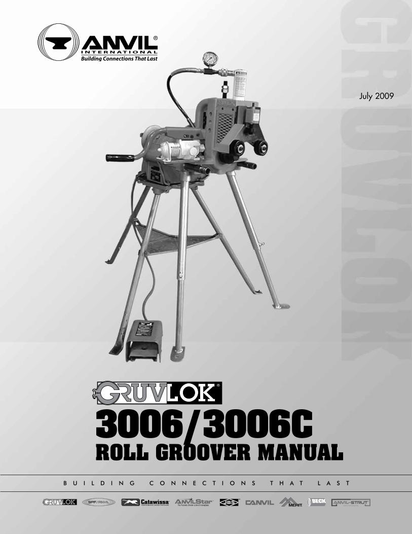
3006/3006CROLL GROOVER MANUAL
b u i l d i n g c o n n e c t i o n s t h a t l a s t
July 2009

B u i l d i n g C o n n e C t i o n s t h at l a s t
For over 150 years, Anvil has worked diligently to build a strong, vibrant tradition of making connections — from pipe to pipe and people to people.
We pride ourselves in providing the finest-quality pipe products and
services with integrity and dedication to superior customer service at all levels.
We provide expertise and product solutions for a wide range of applications,
from plumbing and mechanical, HVAC, industrial and fire protection to mining,
and oil and gas. Our comprehensive line of products includes: grooved pipe
couplings, grooved and plain-end fittings, valves, cast and malleable iron fittings,
forged steel fittings, steel pipe nipples and couplings, pipe hangers and supports,
channel and strut fittings, mining and oil field fittings, along with much more.
As an additional benefit to our customers, Anvil offers a complete and
comprehensive Design Services Analysis for mechanical equipment rooms, to
help you determine the most effective and cost-efficient piping solutions for
your pipe system.
At Anvil, we believe that responsive and accessible customer support
is what makes the difference between simply delivering products —
and delivering solutions.
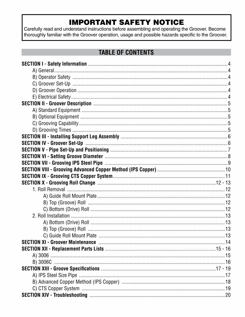
TABLE OF CONTENTS
SECTION I - Safety Information ...........................................................................................................4 A) General .....................................................................................................................................4B) Operator Safety .......................................................................................................................4C) Groover Set-Up .......................................................................................................................4D) Groover Operation ...................................................................................................................4E) Electrical Safety ........................................................................................................................4
SECTION II - Groover Description .......................................................................................................5A) Standard Equipment ................................................................................................................5B) Optional Equipment .................................................................................................................5C) Grooving Capability ..................................................................................................................5D) Grooving Times .......................................................................................................................5
SECTION III - Installing Support Leg Assembly ..................................................................................6SECTION IV - Groover Set-Up .............................................................................................................6SECTION V - Pipe Set-Up and Positioning ..........................................................................................7SECTION VI - Setting Groove Diameter ..............................................................................................8SECTION VII - Grooving IPS Steel Pipe ..............................................................................................9SECTION VIII - Grooving Advanced Copper Method (IPS Copper) ....................................................10SECTION IX - Grooving CTS Copper System ......................................................................................11SECTION X - Grooving Roll Change ...........................................................................................12 - 13 1. Roll Removal .........................................................................................................................12
A) Guide Roll Mount Plate ..................................................................................................12 B) Top (Groove) Roll .........................................................................................................12 C) Bottom (Drive) Roll .......................................................................................................122. Roll Installation ......................................................................................................................13 A) Bottom (Drive) Roll .......................................................................................................13 B) Top (Groove) Roll .........................................................................................................13 C) Guide Roll Mount Plate .................................................................................................13
SECTION XI - Groover Maintenance .................................................................................................14SECTION XII - Replacement Parts Lists .....................................................................................15 - 16
A) 3006 ......................................................................................................................................15B) 3006C ...................................................................................................................................16
SECTION XIII - Groove Specifications ........................................................................................17 - 19 A) IPS Steel Size Pipe ................................................................................................................17 B) Advanced Copper Method (IPS Copper) ...............................................................................18 C) CTS Copper System ..............................................................................................................19SECTION XIV - Troubleshooting ........................................................................................................20
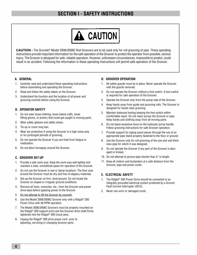
IMPORTANT SAFETY NOTICECarefully read and understand instructions before assembling and operating the Groover. Become thoroughly familiar with the Groover operation, usage and possible hazards specific to the Groover.
4
CAUTION - The Gruvlok® Model 3006/3006C Roll Groovers are to be used only for roll grooving of pipe. These operating instructions pro vide important information for the safe operation of the Groover to protect the operator from possible, serious injury. The Groover is designed for safe, reliable operation. However, unforeseen circumstances, impossible to predict, could result in an accident. Following the information in these operating instructions will permit safe operation of the Groover.
A. GENERAL1. Carefully read and understand these operating instructions
before assembling and operating the Groover.
2. Read and follow the safety labels on the Groover.
3. Understand the function and the location of all power and grooving controls before using the Groover.
B. OPERATOR SAFETY1. Do not wear loose clothing, loose sleeve cuffs, loose
fitting gloves, or jewelry that could get caught in moving parts.
2. Wear safety glasses and safety shoes.
3. Tie-up or cover long hair.
4. Wear ear protection if using the Groover in a high noise area or for prolonged periods of grooving.
5. Do not operate the Groover if you are tired from fatigue or medication.
6. Do not allow horseplay around the Groover.
C. GROOVER SET-UP1. Provide a safe work area. Keep the work area well lighted and
maintain a clear, uncluttered space for operation of the Groover.
2. Do not use the Groover in wet or damp locations. The floor area around the Groover must be dry and free of slippery mate rials.
3. Set-up the Groover on firm, level ground. Do not locate the Groover on sloped or irregular ground conditions.
4. Remove all tools, wrenches, etc., from the Groover and power drive base before applying power to the Groover.
5. Do not attempt to lift the Groover by yourself.
6. Use the Model 3006/3006C Groover only with a Ridgid® 300 Power Drive with 38 RPM operation.
7. The Model 3006/3006C Groovers must be properly mounted on the Ridgid® 300 support arms and the Groover drive shaft firmly tight ened Into the Ridgid® 300 chuck jaws.
8. Unplug the Ridgid® 300 drive power cord prior to adjusting, servicing or changing Groover parts.
D. GROOVER OPERATION1. All safety guards must be in place. Never operate the Groover
with the guards removed.
2. Do not operate the Groover without a foot switch. A foot switch is required for safe operation of the Groover.
3. Operate the Groover only from the pump side of the Groover.
4. Keep hands away from guide and grooving rolls. The Groover is designed for hands clear grooving.
5. Maintain balanced footing keeping the foot switch within comfortable reach. Do not reach across the Groover or pipe. Keep hands and clothing away from all moving parts.
6. Do not place excessive force on the hydraulic pump handle. Follow grooving instructions for safe Groover operation.
7. Provide support for piping spool pieces through the use of an appropriate pipe stand properly fastened to the floor or ground.
8. Use the Groover only for roll grooving of the size and wall thick-ness pipe for which it was designed.
9. Do not operate the Groover if any part of the Groover is dam-aged or broken.
10. Do not attempt to groove pipe shorter than 5” in length.
11. Keep all visitors and bystanders at a safe distance from the Groover, pipe and power cords.
E. ELECTRICAL SAFETY 1. The Ridgid® 300 Power Drive should be connected to an
integrally grounded electrical system protected by a Ground Fault Current Interrupter (GFCI).
2. Never use worn or damaged cords.
SECTION I - SAFETY INSTRUCTIONS
5
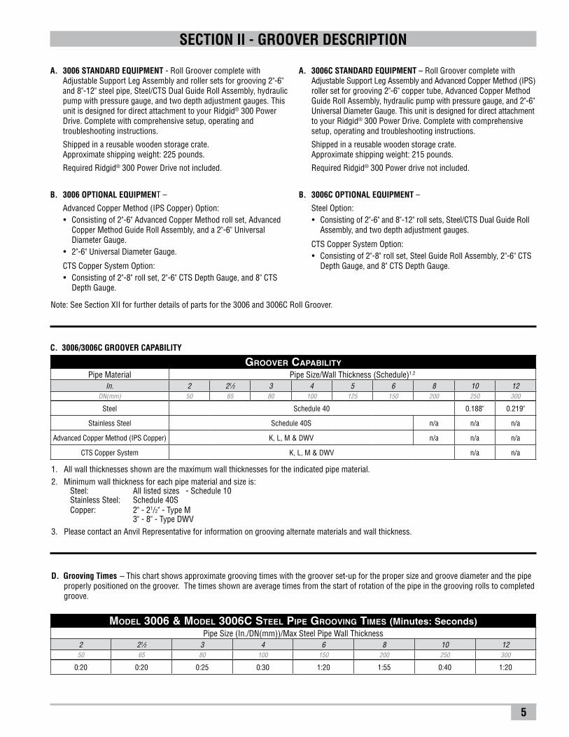
A. 3006 STANDARD EQUIPMENT - Roll Groover complete with Adjustable Support Leg Assembly and roller sets for grooving 2"-6" and 8"-12" steel pipe, Steel/CTS Dual Guide Roll Assembly, hydraulic pump with pressure gauge, and two depth adjustment gauges. This unit is designed for direct attachment to your Ridgid® 300 Power Drive. Complete with comprehensive setup, operating and troubleshooting instructions.
Shipped in a reusable wooden storage crate. Approximate shipping weight: 225 pounds.
Required Ridgid® 300 Power Drive not included.
B. 3006 OPTIONAL EQUIPMENT –
Advanced Copper Method (IPS Copper) Option: • Consistingof2"-6"AdvancedCopperMethodrollset,Advanced
Copper Method Guide Roll Assembly, and a 2"-6" Universal Diameter Gauge.
• 2"-6"UniversalDiameterGauge.
CTS Copper System Option: • Consistingof2"-8"rollset,2"-6"CTSDepthGauge,and8"CTS
Depth Gauge.
A. 3006C STANDARD EQUIPMENT – Roll Groover complete with Adjustable Support Leg Assembly and Advanced Copper Method (IPS) roller set for grooving 2"-6" copper tube, Advanced Copper Method Guide Roll Assembly, hydraulic pump with pressure gauge, and 2"-6" Universal Diameter Gauge. This unit is designed for direct attachment to your Ridgid® 300 Power Drive. Complete with comprehensive setup, operating and troubleshooting instructions.
Shipped in a reusable wooden storage crate. Approximate shipping weight: 215 pounds.
Required Ridgid® 300 Power drive not included.
B. 3006C OPTIONAL EQUIPMENT –
Steel Option: • Consistingof2"-6"and8"-12"rollsets,Steel/CTSDualGuideRoll
Assembly, and two depth adjustment gauges.
CTS Copper System Option: • Consistingof2"-8"rollset,SteelGuideRollAssembly,2"-6"CTS
Depth Gauge, and 8" CTS Depth Gauge.
1. All wall thicknesses shown are the maximum wall thicknesses for the indicated pipe material.2. Minimum wall thickness for each pipe material and size is:
Steel: All listed sizes - Schedule 10Stainless Steel: Schedule 40SCopper: 2" - 21/2" - Type M 3" - 8" - Type DWV
3. Please contact an Anvil Representative for information on grooving alternate materials and wall thickness.
D. Grooving Times – This chart shows approximate grooving times with the groover set-up for the proper size and groove diameter and the pipe properly positioned on the groover. The times shown are average times from the start of rotation of the pipe in the grooving rolls to completed groove.
C. 3006/3006C GROOVER CAPABILITY
Note: See Section XII for further details of parts for the 3006 and 3006C Roll Groover.
SECTION II - GROOVER DESCRIPTION
Groover Capability
Pipe Material Pipe Size/Wall Thickness (Schedule)1,2
In. 2 21⁄2 3 4 5 6 8 10 12DN(mm) 50 65 80 100 125 150 200 250 300
Steel Schedule 40 0.188" 0.219"
Stainless Steel Schedule 40S n/a n/a n/a
Advanced Copper Method (IPS Copper) K, L, M & DWV n/a n/a n/a
CTS Copper System K, L, M & DWV n/a n/a
Model 3006 & Model 3006C Steel Pipe Grooving Times (Minutes: Seconds)Pipe Size (In./DN(mm))/Max Steel Pipe Wall Thickness
2 21⁄2 3 4 6 8 10 1250 65 80 100 150 200 250 300
0:20 0:20 0:25 0:30 1:20 1:55 0:40 1:20
6
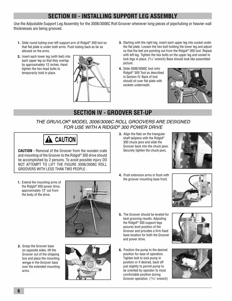
6. Position the pump to the desired position for ease of operation. Tighten bolt to lock pump in position or if desired, back off just slightly to permit pump to be oriented by operator to most comfortable position during Groover operation. (15⁄16" wrench)
3. Starting with the right leg, insert each upper leg into socket under the flat plate. Loosen the hex bolt holding the lower leg and adjust so that the feet are pointing out from the Ridgid® 300 tool. Repeat with left leg. Tighten the hex bolts on the upper leg and socket to lock legs in place. (9/16" wrench) Base should look like assembled picture.
4. Slide 3006/3006C tool onto Ridgid® 300 Tool as described
in Section IV. Back of tool should sit over flat plate with sockets underneath.
1. Extend the mounting arms of the Ridgid® 300 power drive, approximately 12" out from the body of the drive.
2. Grasp the Groover base on opposite sides, lift the Groover out of the shipping box and place the mounting wings in the Groover base over the extended mounting arms.
3. Align the flats on the triangular shaft tailpiece with the Ridgid® 300 chuck jaws and slide the Groover back into the chuck jaws. Securely tighten the chuck jaws. CAUTION - Removal of the Groover from the wooden crate
and mounting of the Groover to the Ridgid® 300 drive should be accomplished by 2 persons. To avoid possible injury DO NOT ATTEMPT TO LIFT THE FIGURE 3006/3006C ROLL GROOVERS WITH LESS THAN TWO PEOPLE .
Use the Adjustable Support Leg Assembly for the 3006/3006C Roll Groover whenever long pieces of pipe/tubing or heavier wall thicknesses are being grooved.
SECTION III - INSTALLING SUPPORT LEG ASSEMBLY
1. Slide round tubing over left support arm of Ridgid® 300 tool so that flat plate is under both arms. Push tubing back as far as allowed on the arms.
2. Insert each lower leg (with feet) into each upper leg so that they overlap by approximately 12 inches. Hand tighten the hex head bolts to temporarily hold in place.
SECTION IV - GROOVER SET-UPTHE GRUVLOK® MODEL 3006/3006C ROLL GROOVERS ARE DESIGNED
FOR USE WITH A RIDGID® 300 POWER DRIVE
4. Push extension arms in flush with the groover mounting base front.
5. The Groover should be leveled for best grooving results. Adjusting the Ridgid® 300 support legs assures level position of the Groover and provides a firm fixed base location for both the Groover and power drive.
7
4. Close the release valve on the hydraulic pump by turning the knob
clockwise. Pump the hydraulic hand pump to lower the top grooving roll into light firm contact (approx. 100 psi) with the pipe.
Make sure that the groove diameter stop (consisting of two 7/8-14 hex nut located on the top
back of the Groover) is not in contact with the top surface of the housing. If contact is noted, release hydraulic pressure by turning the release valve knob counterclockwise allowing the groover head to raise upward. Turn the nut counterclockwise sufficiently to allow clearance between the bottom of nut and top of housing when the top grooving roll is in contact with the pipe.
SECTION V - PIPE SET-UP & POSITIONING
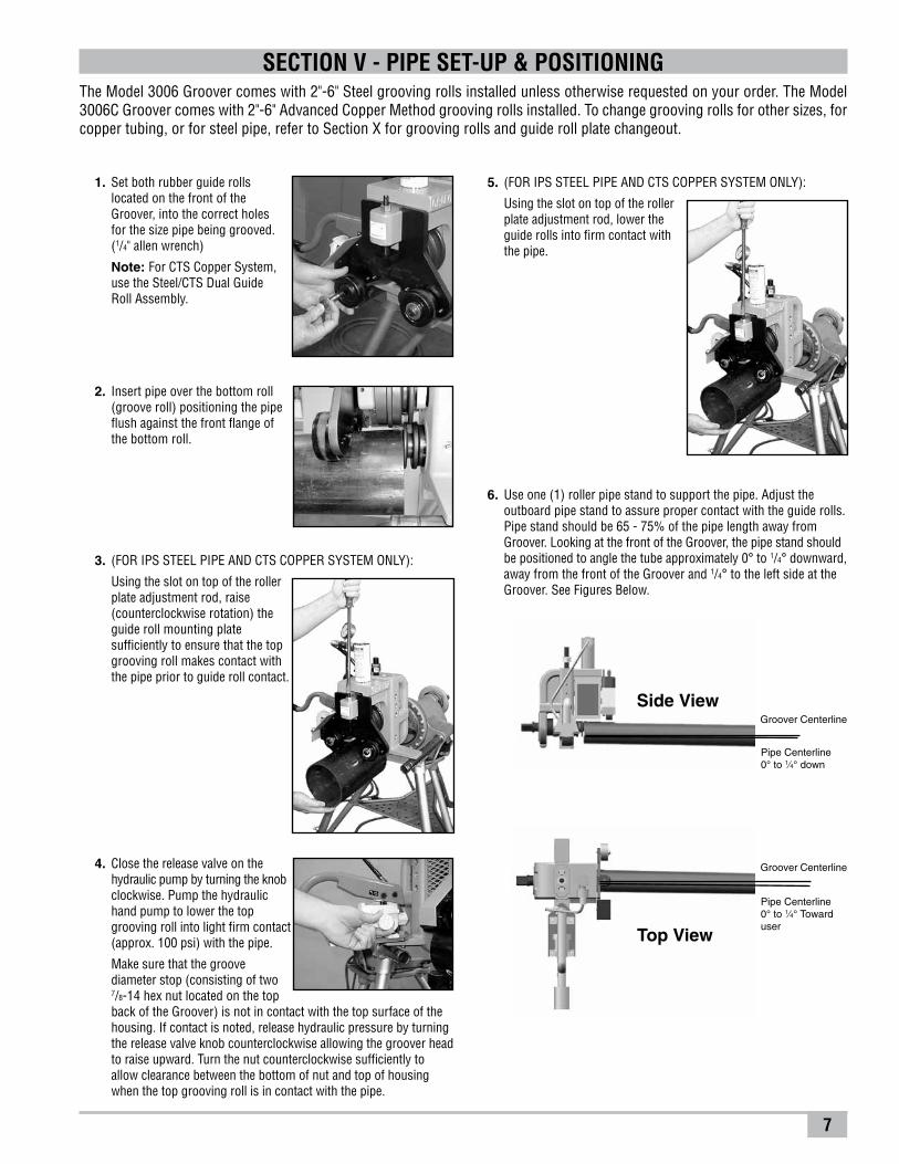
Groover Centerline
Top View
Pipe Centerline 0° to 1⁄4° Toward user
Side ViewGroover Centerline
Pipe Centerline 0° to 1⁄4° down
The Model 3006 Groover comes with 2"-6" Steel grooving rolls installed unless otherwise requested on your order. The Model 3006C Groover comes with 2"-6" Advanced Copper Method grooving rolls installed. To change grooving rolls for other sizes, for copper tubing, or for steel pipe, refer to Section X for grooving rolls and guide roll plate changeout.
1. Set both rubber guide rolls located on the front of the Groover, into the correct holes for the size pipe being grooved. (1/4" allen wrench)
Note: For CTS Copper System, use the Steel/CTS Dual Guide Roll Assembly.
2. Insert pipe over the bottom roll (groove roll) positioning the pipe flush against the front flange of the bottom roll.
3. (FOR IPS STEEL PIPE AND CTS COPPER SYSTEM ONLY):
Using the slot on top of the roller plate adjustment rod, raise (counterclockwise rotation) the guide roll mounting plate sufficiently to ensure that the top grooving roll makes contact with the pipe prior to guide roll contact.
5. (FOR IPS STEEL PIPE AND CTS COPPER SYSTEM ONLY):
Using the slot on top of the roller plate adjustment rod, lower the guide rolls into firm contact with the pipe.
6. Use one (1) roller pipe stand to support the pipe. Adjust the outboard pipe stand to assure proper contact with the guide rolls. Pipe stand should be 65 - 75% of the pipe length away from Groover. Looking at the front of the Groover, the pipe stand should be positioned to angle the tube approximately 0° to 1/4° downward, away from the front of the Groover and 1/4° to the left side at the Groover. See Figures Below.
8
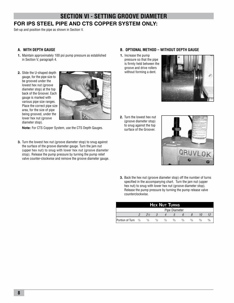
2. Slide the U-shaped depth gauge, for the pipe size to be grooved under the lowest hex nut (groove diameter stop) at the top back of the Groover. Each gauge is marked with various pipe size ranges. Place the correct pipe size area, for the size of pipe being grooved, under the lower hex nut (groove diameter stop).
Note: For CTS Copper System, use the CTS Depth Gauges.
B. OPTIONAL METHOD – WITHOUT DEPTH GAUGE1. Increase the pump
pressure so that the pipe is firmly held between the groove and drive rollers without forming a dent.
FOR IPS STEEL PIPE AND CTS COPPER SYSTEM ONLY:Set-up and position the pipe as shown in Section V.
SECTION VI - SETTING GROOVE DIAMETER
A. WITH DEPTH GAUGE1. Maintain approximately 100 psi pump pressure as established in Section V, paragraph 4.
3. Turn the lowest hex nut (groove diameter stop) to snug against the surface of the groove diameter gauge. Turn the jam nut (upper hex nut) to snug with lower hex nut (groove diameter stop). Release the pump pressure by turning the pump relief valve counter-clockwise and remove the groove diameter gauge.
2. Turn the lowest hex nut (groove diameter stop) to snug against the top surface of the Groover.
3. Back the hex nut (groove diameter stop) off the number of turns specified in the accompanying chart. Turn the jam nut (upper hex nut) to snug with lower hex nut (groove diameter stop). Release the pump pressure by turning the pump release valve counterclockwise.
Hex Nut Turns
Pipe Diameter2 21⁄2 3 4 5 6 8 10 12
Portion of Turn 1/2 1/2 1/2 1/2 2/3 2/3 2/3 2/3 5/6
9
4. Maintain grooving force until the hex nut (groove diameter stop) comes into full, firm contact with the top of the groover base head. Allow the pipe to rotate 1 to 2 revolutions assuring comple tion of the groove. Release the foot switch to allow the pipe to stop rota tion.
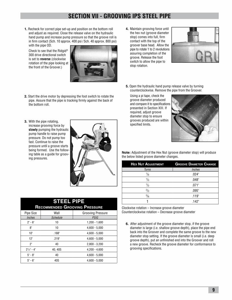
SECTION VII - GROOVING IPS STEEL PIPE
1. Recheck for correct pipe set-up and position on the bottom roll and adjust as required. Close the release valve on the hydraulic hand pump and increase pump pressure so that the groove roll is in firm contact (Sch. 10 approx. 400 psi / Sch. 40 approx. 800 psi) with the pipe OD.
Check to see that the Ridgid® 300 drive directional switch is set to reverse (clockwise rotation of the pipe looking at the front of the Groover.)
2. Start the drive motor by depressing the foot switch to rotate the pipe. Assure that the pipe is tracking firmly against the back of the bottom roll.
3. With the pipe rotating, increase grooving force by slowly pumping the hydraulic pump handle to raise pump pressure. Do not pump too fast. Continue to raise the pressure until a groove starts being formed. Use the follow-ing table as a guide for groov-ing pressures.
5. Open the hydraulic hand pump release valve by turning counterclockwise. Remove the pipe from the Groover.
Using a pi tape, check the groove diameter produced and compare it to specifications presented in Section XIII. If required, adjust groove diameter stop to ensure grooves produced are within specified limits.
6. After adjustment of the groove diameter stop, if the groove diameter is large (i.e. shallow groove depth), place the pipe end back into the Groover and complete the same groove to the new diameter stop setting. If the groove diameter is small (i.e. deep groove depth), put an unfinished end into the Groover and roll a new groove. Recheck the groove diameter for conformance to grooving specifications.
STEEL PIPERecommended Grooving Pressure
Pipe Size Wall Grooving PressureInches Schedule PSIG
2" - 6" 10 1,200 - 1,600
8" 10 4,600 - 5,000
10" .188" 4,600 - 5,000
12" .219" 4,600 - 5,000
2" 40 2,800 - 3,200
21/2" - 4" 40, 40S 4,200 - 4,600
5" - 8" 40 4,600 - 5,000
5" - 6" 40S 4,600 - 5,000
Hex nut adjustment groove diameter cHange
Turns Inches1/6 .024"1/3 .048"1/2 .071"2/3 .095"5/6 .119"
1 .142"
Note: Adjustment of the Hex Nut (groove diameter stop) will produce the below listed groove diameter changes.
Clockwise rotation – Increase groove diameterCounterclockwise rotation – Decrease groove diameter
10
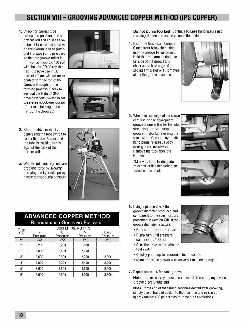
1. Check for correct tube set-up and position on the bottom roll and adjust as re-quired. Close the release valve on the hydraulic hand pump and increase pump pressure so that the groove roll is in firm contact (approx. 400 psi) with the tube OD. Verify that hex nuts have been fully backed off and will not make contact with the top of the Groover throughout the forming process. Check to see that the Ridgid® 300 drive directional switch is set to reverse (clockwise rotation of the tube looking at the front of the Groover.)
5. When the lead edge of the sleeve centers* on the appropriate groove diameter line for the tube size being grooved, stop the groover motor by releasing the foot switch. Open the hydraulic hand pump release valve by turning counterclockwise. Remove the tube from the Groover.
*May vary from leading edge to center of line depending on actual gauge used.
SECTION VIII – GROOVING ADVANCED COPPER METHOD (IPS COPPER)
Do not pump too fast. Continue to raise the pressure until reaching the recommended value in the table.
4. Insert the Universal Diameter Gauge from below the tubing into the groove being formed. Hold the fixed arm against the far side of the groove and observe the lead edge of the sliding arm’s sleeve as it moves along the groove diameter.
6. Using a pi tape check the groove diameter produced and compare it to the specifications presented in Section XIII. If the groove diameter is small:• Re-inserttubeintoGroover.• Pumpramuntilpressure
gauge reads 100 psi.• Startthedrivemotorwiththe
foot switch.• Quicklypumpuptorecommendedpressure.• Monitorgroovegrowthwithuniversaldiametergauge.
7. Repeat steps 1-6 for each groove.
Note: It is necessary to use the universal diameter gauge while grooving every tube end.
Note: If the end of the tubing becomes dented after grooving, simply place that end back into the machine and re-run at approximately 400 psi for two to three tube revolutions.
2. Start the drive motor by depressing the foot switch to rotate the tube. Assure that the tube is tracking firmly against the back of the bottom roll.
3. With the tube rotating, increase grooving force by slowly pumping the hydraulic pump handle to raise pump pressure.
ADVANCED COPPER METHODRecommended Grooving Pressure
TubeSize
COPPER TUBING TYPEK
PressureL
PressureM
PressureDWV
PressureIn. PSI PSI PSI PSI
2" 2,200 2,200 1,800 –
21/2" 2,600 2,600 2,200 –
3" 2,600 2,600 2,200 2,200
4" 3,000 3,000 2,400 2,200
5" 3,600 3,600 3,600 2,600
6" 4,600 4,600 4,000 3,600
11
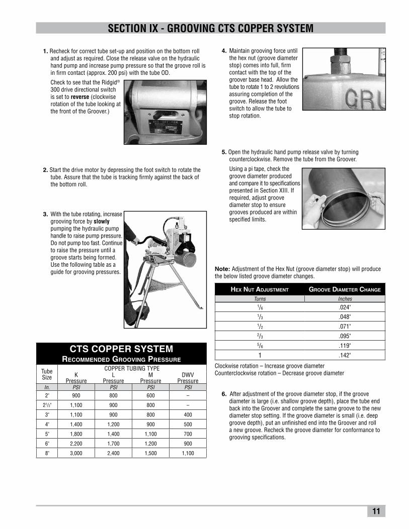
4. Maintain grooving force until the hex nut (groove diameter stop) comes into full, firm contact with the top of the groover base head. Allow the tube to rotate 1 to 2 revolutions assuring comple tion of the groove. Release the foot switch to allow the tube to stop rota tion.
SECTION IX - GROOVING CTS COPPER SYSTEM
1. Recheck for correct tube set-up and position on the bottom roll and adjust as required. Close the release valve on the hydraulic hand pump and increase pump pressure so that the groove roll is in firm contact (approx. 200 psi) with the tube OD.
Check to see that the Ridgid® 300 drive directional switch is set to reverse (clockwise rotation of the tube looking at the front of the Groover.)
2. Start the drive motor by depressing the foot switch to rotate the tube. Assure that the tube is tracking firmly against the back of the bottom roll.
3. With the tube rotating, increase grooving force by slowly pumping the hydraulic pump handle to raise pump pressure. Do not pump too fast. Continue to raise the pressure until a groove starts being formed. Use the following table as a guide for grooving pressures.
5. Open the hydraulic hand pump release valve by turning counterclockwise. Remove the tube from the Groover.
Using a pi tape, check the groove diameter produced and compare it to specifications presented in Section XIII. If required, adjust groove diameter stop to ensure grooves produced are within specified limits.
6. After adjustment of the groove diameter stop, if the groove diameter is large (i.e. shallow groove depth), place the tube end back into the Groover and complete the same groove to the new diameter stop setting. If the groove diameter is small (i.e. deep groove depth), put an unfinished end into the Groover and roll a new groove. Recheck the groove diameter for conformance to grooving specifications.
Hex nut adjustment groove diameter cHange
Turns Inches1/6 .024"1/3 .048"1/2 .071"2/3 .095"5/6 .119"
1 .142"
Note: Adjustment of the Hex Nut (groove diameter stop) will produce the below listed groove diameter changes.
Clockwise rotation – Increase groove diameterCounterclockwise rotation – Decrease groove diameter
CTS COPPER SYSTEMRecommended Grooving Pressure
TubeSize
COPPER TUBING TYPEK
PressureL
PressureM
PressureDWV
PressureIn. PSI PSI PSI PSI
2" 900 800 600 –
21/2" 1,100 900 800 –
3" 1,100 900 800 400
4" 1,400 1,200 900 500
5" 1,800 1,400 1,100 700
6" 2,200 1,700 1,200 900
8" 3,000 2,400 1,500 1,100
12
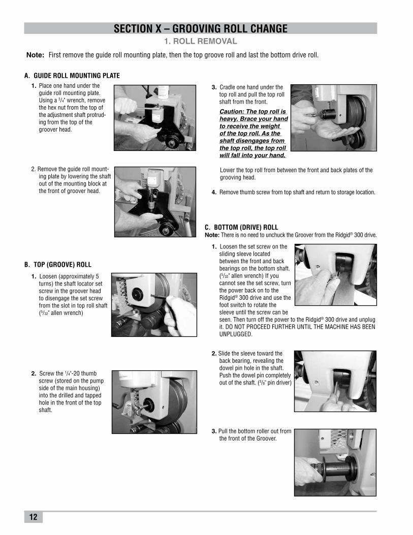
1. Loosen the set screw on the sliding sleeve located between the front and back bearings on the bottom shaft.(5/32" allen wrench) If you cannot see the set screw, turn the power back on to the Ridgid® 300 drive and use the foot switch to rotate the sleeve until the screw can be seen. Then turn off the power to the Ridgid® 300 drive and unplug it. DO NOT PROCEED FURTHER UNTIL THE MACHINE HAS BEEN UNPLUGGED.
3. Cradle one hand under the top roll and pull the top roll shaft from the front.
Caution: The top roll is heavy. Brace your hand to receive the weight of the top roll. As the shaft disengages from the top roll, the top roll will fall into your hand.
SECTION X – GROOVING ROLL CHANGE
1. Loosen (approximately 5 turns) the shaft locator set screw in the groover head to disengage the set screw from the slot in top roll shaft (5/32" allen wrench)
2. Screw the 1/4"-20 thumb screw (stored on the pump side of the main housing) into the drilled and tapped hole in the front of the top shaft.
Lower the top roll from between the front and back plates of the grooving head.
4. Remove thumb screw from top shaft and return to storage location.
B. TOP (GROOVE) ROLL
A. GUIDE ROLL MOUNTING PLATE1. Place one hand under the
guide roll mounting plate. Using a 3/4" wrench, remove the hex nut from the top of the adjustment shaft protrud-
ing from the top of the groover head.
2. Remove the guide roll mount-ing plate by lowering the shaft out of the mounting block at the front of groover head.
C. BOTTOM (DRIVE) ROLLNote: There is no need to unchuck the Groover from the Ridgid® 300 drive.
2. Slide the sleeve toward the back bearing, revealing the dowel pin hole in the shaft. Push the dowel pin completely out of the shaft. (3/8" pin driver)
3. Pull the bottom roller out from the front of the Groover.
1. ROLL REMOVAL
Note: First remove the guide roll mounting plate, then the top groove roll and last the bottom drive roll.

13
SECTION X – GROOVING ROLL CHANGE2. ROLL INSTALLATION
A. BOTTOM (DRIVE) ROLL1. Insert the bottom roll shaft through the front of the groover.
2. Rotate the bottom roll to align the dowel pin hole on the side of the machine.
3. Insert the dowel pin until it is flush with the bottom shaft surface.
4. Slide the retaining sleeve over the dowel pin hole and tighten the set screw.
(5⁄32" allen wrench)
B. TOP (GROOVE) ROLL1. Raise the groove roll
between the front and back plates of the groover head. The deep slot in the top roller should be located toward the back of the groover.
2. Insert the top shaft into the front of the machine so that the V-groove is towards the front. Push the shaft back-ward until the front is
approximately even with the front face of the machine.
3. Tighten the locator socket setscrew (5/32" allen wrench).This will align the V-groove with the locator setscrew in the groover head. Care should be taken to avoid contacting the plain diameter of the shaft.
C. GUIDE ROLL MOUNTING PLATESelect the correct mounting plate for either steel pipe or for copper tube.
1. Insert the adjustment shaft from the bottom, into the hole in the mounting block at the front of the groover head.
2. Slide the shaft up to expose the threaded portion at the top of mounting block.
3. Using a 3⁄4" wrench, install and snug the hex nut on the top of the adjustment shaft.
14
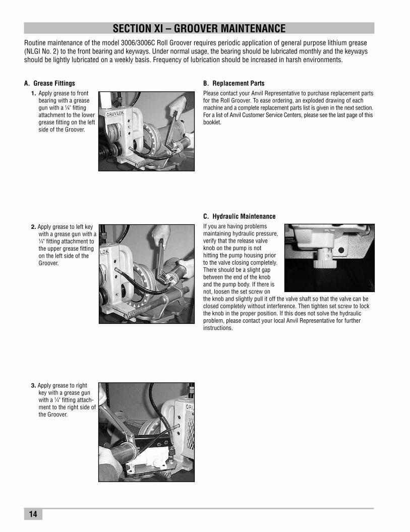
C. Hydraulic MaintenanceIf you are having problemsmaintaining hydraulic pressure,verify that the release valve knob on the pump is nothitting the pump housing priorto the valve closing completely.There should be a slight gapbetween the end of the knoband the pump body. If there isnot, loosen the set screw onthe knob and slightly pull it off the valve shaft so that the valve can beclosed completely without interference. Then tighten set screw to lockthe knob in the proper position. If this does not solve the hydraulicproblem, please contact your local Anvil Representative for furtherinstructions.
SECTION XI – GROOVER MAINTENANCERoutine maintenance of the model 3006/3006C Roll Groover requires periodic application of general purpose lithium grease (NLGI No. 2) to the front bearing and keyways. Under normal usage, the bearing should be lubricated monthly and the keyways should be lightly lubricated on a weekly basis. Frequency of lubrication should be increased in harsh environments.
A. Grease Fittings1. Apply grease to front
bearing with a grease gun with a 1⁄4" fitting attachment to the lower grease fitting on the left side of the Groover.
2. Apply grease to left key with a grease gun with a 1⁄4" fitting attachment to the upper grease fitting on the left side of the Groover.
3. Apply grease to right key with a grease gun with a 1⁄4" fitting attach-ment to the right side of the Groover.
B. Replacement PartsPlease contact your Anvil Representative to purchase replacement parts for the Roll Groover. To ease ordering, an exploded drawing of each machine and a complete replacement parts list is given in the next section. For a list of Anvil Customer Service Centers, please see the last page of this booklet.
15
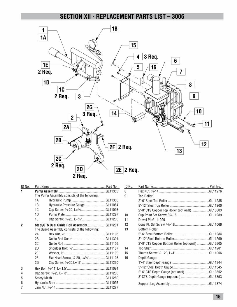
SECTION XII - REPLACEMENT PARTS LIST – 3006
ID No. Part Name ................................................................ Part No.1 Pump Assembly ......................................................GL11355
The Pump Assembly consists of the following:1A Hydraulic Pump .......................................GL113561B Hydraulic Pressure Gauge ........................GL110841C Cap Screw, 1⁄4-20, L= 5⁄8 ............................GL110931D Pump Plate ..............................................GL112971E Cap Screw, 1⁄4-20, L= 1⁄2" ...........................GL11230
2 Steel/CTS Dual Guide Roll Assembly .....................GL11291The Guard Assembly consists of the following:2A Hex Nut, 1⁄2" ..............................................GL111982B Guide Roll Guard ......................................GL113042C Guide Roll ................................................GL111062D Shoulder Bolt, 1⁄2" .....................................GL111072E Washer, 1⁄2" ...............................................GL111092F Flat Head Screw, 1⁄4-20, L=3⁄4" ...................GL111082G Cap Screw, 1⁄4-20,L= 1⁄2" ...........................GL11230
3 Hex Bolt, 5⁄8-11, L= 1.5" ............................................GL110914 Cap Screw, 1⁄4-20,L= 1⁄2" ............................................GL112305 Safety Mesh .............................................................GL112806 Hydraulic Ram .........................................................GL110957 Jam Nut, 7⁄8-14 .........................................................GL11277
ID No. Part Name ................................................................ Part No.8 Hex Nut, 7⁄8-14 ..........................................................GL112769 Top Roller: 2"-6" Steel Top Roller ...............................................GL11285 8"-12" Steel Top Roller .............................................GL11300 2"-8" CTS Copper Top Roller (optional) ....................GL1380310 Cup Point Set Screw, 5⁄16-18 .....................................GL1128911 Dowel Pin GL1129012 Cone Pt. Set Screw, 5⁄16-18 .......................................GL1106613 Bottom Roller: 2"-6" Steel Bottom Roller ..........................................GL11284 8"-12" Steel Bottom Roller ........................................GL11299 2"-8" CTS Copper Bottom Roller (optional) ..............GL1380514 Top Shaft ..................................................................GL1128115 Thumb Screw 1⁄4 - 20, L=1" ......................................GL1105616 Depth Gauge:
1"-4" Steel Depth Gauge ...........................................GL113445"-12" Steel Depth Gauge .........................................GL11345
2"-6" CTS Depth Gauge (optional) ............................GL13852 8" CTS Depth Gauge (optional) ................................GL13853
Support Leg Assembly .............................................GL11374
4
2 Req.
2 Req.
2 Req.
2 Req.
3 Req.
2 Req.
2 Req.
3 Req.
5
15
1B
166
7
8
9
10
11
12 13
2F
2E2D
2C
2B
2A
2
2G14
31C
1A1
1D
1E

16
SECTION XII - REPLACEMENT PARTS LIST – 3006C
ID No. Part Name ................................................................ Part No.
1 Pump Assembly ......................................................GL11355The Pump Assembly consists of the following:
1A Hydraulic Pump .......................................GL11356
1B Hydraulic Pressure Gauge ........................GL11084
1C Cap Screw, 1⁄4-20, L= 5⁄8 ............................GL11093
1D Pump Plate ..............................................GL11297
1E Cap Screw, 1⁄4-20, L= 1⁄2" ...........................GL11230
2 Advanced Copper Guide Roll Assembly (IPS Copper) .GL11352The Guard Assembly consists of the following:
2A Hex Nut, 1⁄2" ..............................................GL11198
2B Guide Roll Guard ......................................GL11304
2C Guide Roll ................................................GL11106
2D Shoulder Bolt, 1⁄2" .....................................GL11107
2E Washer, 1⁄2" ...............................................GL11109
2F Flat Head Screw, 1⁄4-20, L=3⁄4" ...................GL11108
2G Cap Screw, 1⁄4-20,L= 1⁄2" ...........................GL11230
2H C-Clip .......................................................GL11078
ID No. Part Name ................................................................ Part No.
3 Hex Bolt, 5⁄8-11, L= 1.5" ...........................................GL11091
4 Cap Screw, 1⁄4-20,L= 1⁄2" ...........................................GL11230
5 Safety Mesh ............................................................GL11280
6 Hydraulic Ram ........................................................GL11095
7 Jam Nut, 7⁄8-14 ........................................................GL11277
8 Hex Nut, 7⁄8-14 .........................................................GL11276
9 2"-6" Advanced Copper Top Roller...........................GL11122
10 Cup Point Set Screw, 5⁄16-18 ....................................GL11289
11 Dowel Pin ................................................................GL11290
12 Cone Pt. Set Screw, 5⁄16-18 ......................................GL11066
13 2"-6" Advanced Copper Bottom Roller .....................GL11349
14 Top Shaft .................................................................GL11281
15 Thumb Screw 1⁄4 - 20, L=1" .....................................GL11056
16 Universal 2"-6" Diameter Gauge ..............................GL11133
Support Leg Assembly ............................................GL11374
4
2 Req.
2 Req.
2 Req.
2 Req.
3 Req.
2 Req.
2 Req.
3 Req.
5
15
1B
6
7
8
9
10
11
12 13
2F
2E2D
2C
2B
2A
2 2G
14
31C
1A1
1D
1E
162H
17
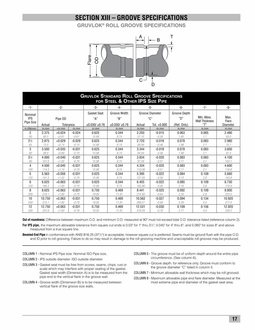
SECTION XIII – GROOVE SPECIFICATIONSGRUVLOK® ROLL GROOVE SPECIFICATIONS
COLUMN 1 - Nominal IPS Pipe size. Nominal ISO Pipe size.
COLUMN 2 - IPS outside diameter. ISO outside diameter.
COLUMN 3 - Gasket seat must be free from scores, seams, chips, rust or scale which may interfere with proper sealing of the gasket. Gasket seat width (Dimension A) is to be measured from the pipe end to the vertical flank in the groove wall.
COLUMN 4 - Groove width (Dimension B) is to be measured between vertical flank of the groove size walls.
Gruvlok Standard Roll Groove Specifications for Steel & OtHer IPS Size Pipe
-1- -2- -3- -4- -5- -6- -7- -8-
Nominal IPS
Pipe Size
Gasket Seat Groove Width Groove Diameter Groove DepthMin. Allow.
Wall Thickness“T”
Max. Flare
Diameter
Pipe OD “A” “B” “C” “D”
Actual Tolerance ±0.030/ ±0.76 ±0.030/ ±0.76 Actual Tol. +0.000 (Ref. Only)In./DN(mm) In./mm +In./mm -In./mm In./mm In./mm In./mm -In./mm In./mm In./mm In./mm
2 2.375 +0.024 -0.024 0.625 0.344 2.250 -0.015 0.063 0.065 2.48050 60.3 +0.61 -0.61 15.88 8.74 57.15 -0.38 1.60 1.7 63.021⁄2 2.875 +0.029 -0.029 0.625 0.344 2.720 -0.018 0.078 0.083 2.98065 73.0 +0.74 -0.74 15.88 8.74 69.09 -0.46 1.98 2.1 75.73 3.500 +0.035 -0.031 0.625 0.344 3.344 -0.018 0.078 0.083 3.60080 88.9 +0.89 -0.79 15.88 8.74 84.94 -0.46 1.98 2.1 91.431⁄2 4.000 +0.040 -0.031 0.625 0.344 3.834 -0.020 0.083 0.083 4.10090 101.6 +1.02 -0.79 15.88 8.74 97.38 -0.51 2.11 2.1 104.14 4.500 +0.045 -0.031 0.625 0.344 4.334 -0.020 0.083 0.083 4.600
100 114.3 +1.14 -0.79 15.88 8.74 110.08 -0.51 2.11 2.1 116.85 5.563 +0.056 -0.031 0.625 0.344 5.395 -0.022 0.084 0.109 5.660
125 141.3 +1.42 -0.79 15.88 8.74 137.03 -0.56 2.13 2.8 143.86 6.625 +0.063 -0.031 0.625 0.344 6.455 -0.022 0.085 0.109 6.730
150 168.3 +1.60 -0.79 15.88 8.74 163.96 -0.56 2.16 2.8 170.98 8.625 +0.063 -0.031 0.750 0.469 8.441 -0.025 0.092 0.109 8.800
200 219.1 +1.60 -0.79 19.05 11.91 214.40 -0.64 2.34 2.8 223.510 10.750 +0.063 -0.031 0.750 0.469 10.562 -0.027 0.094 0.134 10.920250 273.1 +1.60 -0.79 19.05 11.91 268.27 -0.69 2.39 3.4 277.412 12.750 +0.063 -0.031 0.750 0.469 12.531 -0.030 0.109 0.156 12.920300 323.9 +1.60 -0.79 19.05 11.91 318.29 -0.76 2.77 4.0 328.2
TB
DC
OD
Fla
re
A
Out of roundness: Difference between maximum O.D. and minimum O.D. measured at 90° must not exceed total O.D. tolerance listed (reference column 2).
For IPS pipe, the maximum allowable tolerance from square cut ends is 0.03" for 1" thru 31⁄2"; 0.045" for 4" thru 6"; and 0.060" for sizes 8" and above measured from a true square line.
Beveled-End Pipe in conformance with ANSI B16.25 (371⁄2°) is acceptable, however square cut is preferred. Seams must be ground flush with the pipe O.D. and ID prior to roll grooving. Failure to do so may result in damage to the roll grooving machine and unacceptable roll grooves may be produced.
COLUMN 5 - The groove must be of uniform depth around the entire pipe circumference. (See column 6).
COLUMN 6 - Groove depth: for reference only. Groove must conform to the groove diameter “C” listed in column 5.
COLUMN 7 - Minimum allowable wall thickness which may be roll grooved.
COLUMN 8 - Maximum allowable pipe end flare diameter. Measured at the most extreme pipe end diameter of the gasket seat area.

18
SECTION XIII – GROOVE SPECIFICATIONSGRUVLOK® ADVANCED COPPER METHOD: COPPER PREP SPECIFICATIONS
BA T
C
D
ConnectionDiameter
TubeO.D.
Gruvlok Copper prep Roll Groove Specifications for Types K, L, M, and DWV Copper Tubing
-1- -2- -3- -4- -5- -6- -7- -8- -9-
Nominal Tubing
Size
Gasket Seat Groove Width Groove Diameter Groove Depth Allow.Wall
Thickness“T”
Max. Flare
Diameter
Tubing Outside Diameter Tube End Connection Diameter “A” “B” “C” “D”
Actual Tolerance Actual Tolerance ±0.030/ ±0.77 ±0.030/ ±0.77 ActualTol.
+0.000 (Ref. Only)In./DN(mm) In./mm +In./mm -In./mm In./mm +In./mm -In./mm In./mm In./mm In./mm -In./mm In./mm In./mm In./mm
2 2.125 0.002 0.002 2.375 0.045 0.024 0.625 0.344 2.250 -0.015 0.063 0.059 2.44750 54.0 0.05 0.05 60.33 1.14 0.61 15.88 8.74 57.15 -0.381 1.60 1.50 62.1521⁄2 2.625 0.002 0.002 2.875 0.029 0.029 0.625 0.344 2.720 -0.018 0.077 0.065 2.96265 66.7 0.05 0.05 73.03 0.74 0.74 15.88 8.74 69.09 -0.46 1.96 1.65 75.233 3.125 0.002 0.002 3.500 0.035 0.031 0.625 0.344 3.344 -0.018 0.078 DWV 3.56680 79.4 0.05 0.05 88.90 0.89 0.79 15.88 8.74 84.94 -0.46 1.98 90.584 4.125 0.002 0.002 4.500 0.045 0.031 0.625 0.344 4.334 -0.020 0.083 DWV 4.576
100 104.8 0.05 0.05 114.30 1.14 0.79 15.88 8.74 110.08 -0.51 2.11 116.235 5.125 0.002 0.002 5.562 0.056 0.031 0.625 0.344 5.395 -0.022 0.084 DWV 5.650
125 130.2 0.05 0.05 141.27 1.42 0.79 15.88 8.74 137.03 -0.56 2.13 143.516 6.125 0.002 0.002 6.625 0.063 0.031 0.625 0.344 6.455 -0.022 0.085 DWV 6.719
150 155.6 0.05 0.05 168.28 1.60 0.79 15.88 8.74 163.96 -0.56 2.16 170.66
Out of roundness: Difference between maximum O.D. and minimum O.D. measured at 90° must not exceed tolerance listed.
The maximum allowable tolerance from square cut ends is 0.030" for 2" thru 3" and 0.045" for 4" thru 6"; measured from a true square line.
COLUMN 1 - Nominal ASTM B 88 copper tubing size.
COLUMN 2 - Outside diameter of copper tubing in accordance with ASTM B 88.
COLUMN 3 - Outside diameter of Copper Prep roll grooved copper tubing.
COLUMN 4 - Gasket seat and groove must be free from scores, seams, chips, rust or scale which may interfere with proper coupling assembly.
COLUMN 5 - Groove width is to be measured between vertical flank of the groove size walls.
COLUMN 6 - The groove must be of uniform depth around the entire tubing circumference. (See column 7).
COLUMN 7 - Groove depth: for reference only. Groove must conform to the groove diameter “C” listed in column 6.
COLUMN 8 - Minimum allowable copper tube wall thickness which may be prepared to Gruvlok Copper-Prep specifications.
COLUMN 9 - Maximum allowable end flare diameter. Measured at the most extreme tubing end diameter of the gasket seat area.
19
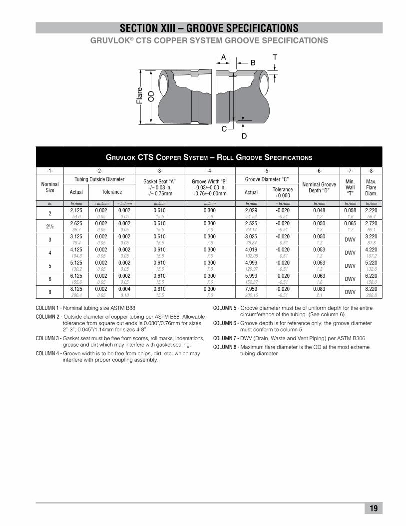
SECTION XIII – GROOVE SPECIFICATIONSGRUVLOK® CTS COPPER SYSTEM GROOVE SPECIFICATIONS
COLUMN 1 - Nominal tubing size ASTM B88
COLUMN 2 - Outside diameter of copper tubing per ASTM B88. Allowable tolerance from square cut ends is 0.030”/0.76mm for sizes 2”-3”; 0.045”/1.14mm for sizes 4-8”
COLUMN 3 - Gasket seat must be free from scores, roll marks, indentations, grease and dirt which may interfere with gasket sealing.
COLUMN 4 - Groove width is to be free from chips, dirt, etc. which may interfere with proper coupling assembly.
COLUMN 5 - Groove diameter must be of uniform depth for the entire circumference of the tubing. (See column 6).
COLUMN 6 - Groove depth is for reference only; the groove diameter must conform to column 5.
COLUMN 7 - DWV (Drain, Waste and Vent Piping) per ASTM B306.
COLUMN 8 - Maximum flare diameter is the OD at the most extreme tubing diameter.
TB
DC
OD
Fla
re
A
gruvlok cts copper system – roll groove specifications
-1- -2- -3- -4- -5- -6- -7- -8-
NominalSize
Tubing Outside Diameter Gasket Seat “A”+/– 0.03 in.+/– 0.76mm
Groove Width “B”+0.03/–0.00 in.+0.76/–0.00mm
Groove Diameter “C”Nominal Groove
Depth “D”
Min.Wall“T”
Max.FlareDiam.Actual Tolerance Actual Tolerance
+0.000In. In./mm + In./mm – In./mm In./mm In./mm In./mm – In./mm In./mm In./mm In./mm
2 2.125 0.002 0.002 0.610 0.300 2.029 -0.020 0.048 0.058 2.22054.0 0.05 0.05 15.5 7.6 51.54 -0.51 1.2 1.6 56.4
21/22.625 0.002 0.002 0.610 0.300 2.525 -0.020 0.050 0.065 2.72066.7 0.05 0.05 15.5 7.6 64.14 -0.51 1.3 1.7 69.1
3 3.125 0.002 0.002 0.610 0.300 3.025 -0.020 0.050 DWV 3.22079.4 0.05 0.05 15.5 7.6 76.84 -0.51 1.3 81.8
4 4.125 0.002 0.002 0.610 0.300 4.019 -0.020 0.053 DWV 4.220104.8 0.05 0.05 15.5 7.6 102.08 -0.51 1.3 107.2
5 5.125 0.002 0.002 0.610 0.300 4.999 -0.020 0.053 DWV 5.220130.2 0.05 0.05 15.5 7.6 126.97 -0.51 1.3 132.6
6 6.125 0.002 0.002 0.610 0.300 5.999 -0.020 0.063 DWV 6.220155.6 0.05 0.05 15.5 7.6 152.37 -0.51 1.6 158.0
8 8.125 0.002 0.004 0.610 0.300 7.959 -0.020 0.083 DWV 8.220206.4 0.05 0.10 15.5 7.6 202.16 -0.51 2.1 208.8

20
TroublesHooting Instructions
Problem Possible Cause Solution
1. Pipe will not stay in grooving rolls
Incorrect pipe positioning.
Improper grooving technique.
Power drive running counterclockwiseModel 3006 / 3007 & 1007.
See "Pipe Set-up & Positioning"
See "Grooving Pipe"
Ridgid 300 check setting in reverseClockwise rotation of pipe
2. Pipe stops rotating during grooving.
Rust or dirt has built up on lower roll.
Worn grooving rolls.
Bottom roll dowel pin is sheared or missing.
Ridgid 300 chuck jaws not engaged properly.
Steel Pipe – Groove Diameter Stop improperly adjusted.
Copper Pipe – Groove Diameter Stop making contact with top surface of Groover.
Remove accumulation from lower roll with stiff wire brush.
Inspect lower rolls for worn knurls, replace if worn.
Replace dowel pin per instructions in Section X.
See "Groover Set-up"
Adjust Groove Diameter Stop to correct IPS.
Verify Groove Diameter Stop Nuts are fully backed off.
3. Pipe flare excessive
Pipe stand adjusted too high.
Tool is tilted forward.
Incorrect pipe stand offset positioning. Pipe isover "tracking".
Warped drive shaft.
See "Pipe Set-up & Positioning"
See "Groover Set-up"
See "Pipe Set-up & Positioning"
The rear collar of the drive shaft is missing. Replace damaged parts.
4.While grooving loud squeaks echo throughthe pipe.
Pipe or Tube not square cut.
Incorrect pipe roller offset positioning Pipe isover "tracking".
Cut pipe or tube ends squarely.
Move pipe stand for proper offset. See "Pipe Set-up& Positioning"
5.During grooving loud thumps or bangs occur about once every revolution of the pipe.
Pipe has a pronounced weld seam. Grind welds flush with pipe surface inside & out 2" back from pipe end.
6. Tool won't groove pipe.
Hand pump is low on oil.
Air in hydraulic system.
Pipe wall thickness exceeds tool's capability.
See "Groover Maintenance"
See "Groover Maintenance"
See "Groover Description"
SECTION XIII – TROUBLESHOOTING

NOTES
B U I L D I N G C O N N E C T I O N S T H A T L A S T
We built our reputation from the ground up.
Anvil’s history stretches back to the mid 1800s,when a company named Grinnell® began providingits customers with the finest quality pipe products.Since 2000, those quality products and services—and the people who provide them—have beenknown as Anvil® International. Anvil® customers receive the quality and integrity that have been building strong connections in both productsand business relationships for over 150 years.
TRUSTEDFOR 150 YEARS
Focused Product Line:
Anvil® Malleable and CastIron Fittings
Anvil® Hangers, Supportsand Struts
Beck Welded Pipe Nipples
Anvil® Seamless PipeNipples
Anvil® Steel Pipe Couplingsand Small Steel Fittings
Merit® Tee-Lets and DropNipples
Gruvlok® Couplings,Fittings and Valves
SPFTM Malleable and Castand Ductile Iron Fittings
SPF TM Grooved Fittings and O’Lets
J.B. Smith Swage Nipplesand Bull Plugs
Catawissa® Wing Unionsand Check Valves
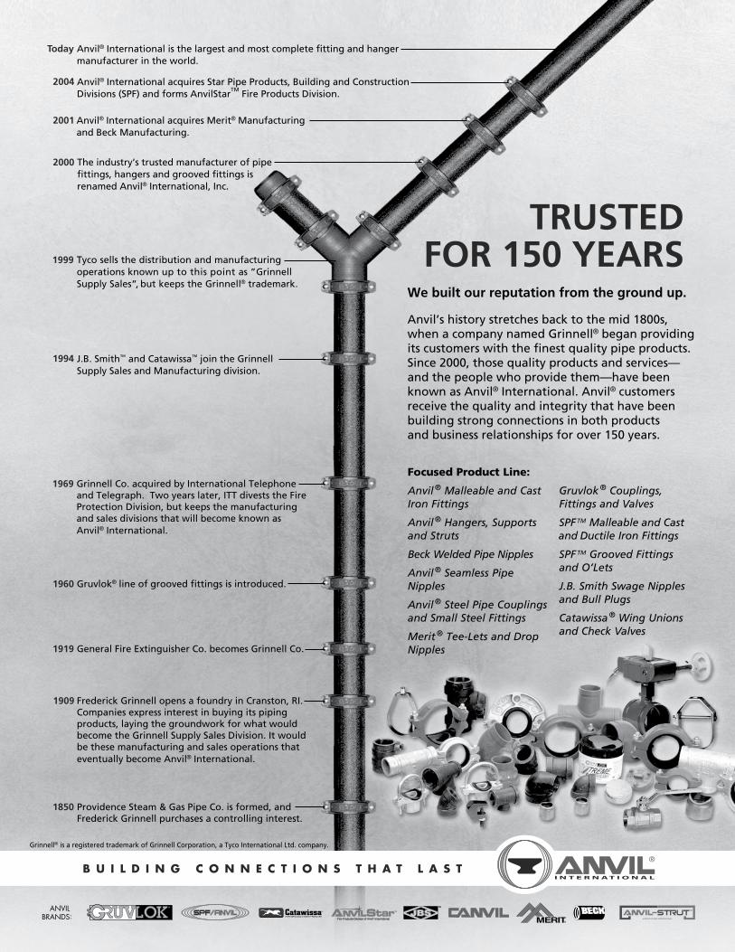
Today Anvil® International is the largest and most complete fitting and hanger manufacturer in the world.
2004 Anvil® International acquires Star Pipe Products, Building and Construction Divisions (SPF) and forms AnvilStar
TM Fire Products Division.
2001 Anvil® International acquires Merit® Manufacturingand Beck Manufacturing.
2000 The industry’s trusted manufacturer of pipefittings, hangers and grooved fittings isrenamed Anvil® International, Inc.
1999 Tyco sells the distribution and manufacturingoperations known up to this point as ”Grinnell Supply Sales”, but keeps the Grinnell® trademark.
1994 J.B. Smith™ and Catawissa™ join the Grinnell Supply Sales and Manufacturing division.
1850 Providence Steam & Gas Pipe Co. is formed, andFrederick Grinnell purchases a controlling interest.
1909 Frederick Grinnell opens a foundry in Cranston, RI.Companies express interest in buying its pipingproducts, laying the groundwork for what wouldbecome the Grinnell Supply Sales Division. It would be these manufacturing and sales operations thateventually become Anvil® International.
1919 General Fire Extinguisher Co. becomes Grinnell Co.
1960 Gruvlok® line of grooved fittings is introduced.
1969 Grinnell Co. acquired by International Telephone and Telegraph. Two years later, ITT divests the FireProtection Division, but keeps the manufacturingand sales divisions that will become known asAnvil® International.
Grinnell® is a registered trademark of Grinnell Corporation, a Tyco International Ltd. company.
ANVIL BRANDS: ®

Anvil® product lines include malleable and cast iron fittings, unions and flanges; seamless steel pipe nipples; steel pipe couplings; universal anvilets; forged steel fittings and unions; pipe hangers and supports; threaded rod; and engineered hangers.
The Gruvlok® product line consists of couplings for grooved and plain-end fittings, butterfly valves and check valves; flanges; pump protection components; pipe grooving tools; as well as copper and stainless steel system components.
Anvil-Strut™ products include a complete line of channel in stock lengths of 10 and 20 feet, with custom lengths available upon request. A variety of fittings and accessories are also offered. All products can be ordered in an assortment of finishes and material choices including SupR-Green™, Zinc Trivalent Chromium, pre-galvanized, hot-dipped galvanized, electro-galvanized, aluminum, plain, and stainless steel.
JB Smith™ is the leading manufacturer of oil country tubular fittings, swages and bull plugs – all meeting API specifications. Offering tubing nipples, casing nipples as well as a full line of traditional line pipe and oil country threads in every schedule, JB Smith is the resource for all your oilfield needs.
Catawissa™ NACE and API approved wing unions for Standard Service are offered in non-pressure seal ends as well as threaded and butt weld, and are interchangeable with most leading union manufacturers. Fully traceable and available with complete mill certifications, Catawissa’s oilfield wing union product line includes the standard ball-and-cone design plus our unique Figure 300 Flat Face design, where space and pipe line separation are a consideration.
AnvilStar™ offers a complete line of products for the fire protection industry, including Gruvlok® couplings, fittings, flanges; valves, and roll groovers; steel pipe nipples and couplings; cast and malleable iron threaded and flanged fittings; pipe hangers and supports; Merit® tee-lets, drop nipples; steel welding flanges; SPF grooved couplings, fittings, and flanges; SPF cast iron and ductile iron threaded fittings, o’lets, steel pipe nipples; and Mueller valves and indicator posts.
The SPF/Anvil™ product line includes a variety of internationally sourced products such as grooved couplings, fittings and flanges, cast iron, malleable iron and ductile iron threaded fittings, steel pipe nipples, as well as o’lets.
The Merit® product line includes a variety of tee-lets, drop nipples, and steel welding flanges for fire protection applications. Most Merit products are UL/ULC Listed, FM Approved, and rated from 175 to 300 psi.
Beck steel pipe nipples and steel pipe couplings are manufactured in accordance with the ASTM A733 Standard Specification for Welded and Seamless Carbon Steel and Stainless Steel Pipe Nipples. Steel pipe couplings are manufactured in accordance with the ASTM A865 Standard Specification for Threaded Couplings, Steel, Black or Zinc-Coated (Galvanized) Welded or Seamless, for Use in Steel Pipe Joints. Beck API couplings are manufactured in accordance with the API Specification for line pipe.
Canvil® manufactures low pressure hexagon reducer bushings, as well as plugs and hex caps up to 1” in diameter in various finishes including Oil Treat, Phosphate and Electro Galvanized. In addition, Canvil manufactures A105 hex or round material in class 3000 and 6000 pound, forged steel couplings and bar stock products offered as either as normalized (A105N) or non-normalized (A105) that are fully traceable for mechanicals and chemistry through our MTR program.
B r a n d s o f a n v i l i n t e r n at i o n a l

#117/Printed in USA/RPI/5M/© Copyright 2009Revision Date: 6.23.09
Corporate offices110 Corporate Drive, Suite 10 P.O. Box 3180 Portsmouth, NH 03802-3180
Tel: 603-422-8000 Fax: 603-422-8033
E-mail: [email protected]
anvil international WorldwideCustomer service CenterTel: 708-885-3000 Fax: 708-534-5441
u.s. regional serviCe Centers
anvil international CanadaCustomer Service Center390 Second AvenueP.O. Box 40Simcoe, Ontario N3Y 4K9
Tel: 519-426-4551Fax: 519-426-5509
Canada serviCe Center
www.anvilintl.com
b u i l d i n g c o n n e c t i o n s t h a t l a s t
northern regionRegional Distribution & Customer Service CenterSeRviCing: Illinois, Indiana, Iowa, Kentucky, Michigan, Minnesota, Nebraska, North and South Dakota, Ohio,West Pennsylvania, West Virginia, Wisconsin
750 Central Avenue University Park, IL 60484
Tel: 708-885-3000 Fax: 708-534-5441 Toll Free: 1-800-301-2701
southern regionRegional Distribution & Customer Service CenterSeRviCing: Alabama, Arkansas, Kansas, Louisiana, Mississippi, Missouri, Oklahoma, Tennessee, Texas
1401 Valley View Lane, Suite 150Irving, TX 75061
Tel: 972-343-9206 Fax: 972-641-8946 Toll Free: 1-800-451-4414
eastern regionRegional Distribution CenterSeRviCing: Connecticut, Delaware, Florida, Georgia, Maine, Maryland, Massachusetts, New Hampshire, New Jersey,New York, North and South Carolina, East Pennsylvania,Rhode Island, Vermont, Virginia
800 Malleable Road Columbia, PA 17512
Western regionRegional Distribution CenterSeRviCing: Alaska, Arizona, California, Colorado, Hawaii, Idaho, Montana, Nevada, New Mexico, Oregon, Utah, Washington, Wyoming
1385 Greg Street Sparks, NV 89431
international sales
Mexico, Puerto rico andlatin americaAbraham Quijada, Sales [email protected]
Tel: +1-281-590-4600
U.S. Customer Service Tel: +1-708-885-3000 Fax: +1-708-534-5441
europe and Middle east regionRick van Meesen, Sales DirectorThe [email protected]
Tel: +31-53-5725570 Fax: +31-53-5725579
U.S. Customer Service Tel: +1-708-885-3000 Fax: +1-708-534-5441


![Menu 2015.pdfRM12 [N] Dishes with nuts ohol Sushi Roll + SPICY SEAFOOD ROLL + DRAGON ROLL IA) DEEP-FRIED SOFT SHELL CRAB ROLL CALIFORNIA ROLL SALMON SKIN ROLL IA) UNAGI ROLL RM47 RM53](https://img.pdfslide.net/doc/110x75/5ed75f27acc46829cb3402b3/menu-2015pdf-rm12-n-dishes-with-nuts-ohol-sushi-roll-spicy-seafood-roll-dragon.jpg)