Embed Size (px)
Citation preview

Comfort Air CurtainsModel CITY
Simply effective
CITY.CEE-en-2014-10-PDF•14102854

Comfort Air CurtainsInviting and comfortable
An open door to a shop or public building breaks down barriers and is inviting. Butwithout proper separation of the indoor and outdoor air, the climate in the buildingwill be affected. Customers and staff will be faced with draughts caused by coldoutside air entering the building, while costly hot indoor air can freely escape to theoutside. In winter a Biddle comfort air curtain warms the cold outside air before itenters the shop, while at the same preventing the warm inside air from escaping,through the open door. This is pleasant, both for customers and staff as well as forthe energy bill. In summer, a continuous re-circulation of indoor air prevents theinfluences from hot outside air on the inner climate. So, also in summer the air curtainsaves energy and maintains a stable inner climate.
Optimal efficiency
Comfort air curtain, model CITY is suitable for buildings on a favourable location withstable weather circumstances, such as shops in sheltered shopping streets. In suchlocations, the air curtain will not need to respond frequently to changing conditions,so it can operate properly at one fixed speed most of the time. Because of the rectifiertechnology the comfort is very high (low air velocity) and warm air stays inside whichresults in an optimal efficiency. The air curtain is easy to control with the 3-speedcontroller. Because of the austere and neutral design the CITY integrates well in allinteriors.
Application
Biddle Comfort Air Curtains are highly suitable for use in shops, supermarkets, publicbuildings, hotels and hospitals.
Comfort air curtains, model CITY
Model CITY provides for optimum climateseparation.
2

Features model CITY
High comfort and efficiency Low sound level Easy to use and maintain Suitable, as standard, for low water temperature (60ºC/40ºC) Ready for operation because of plug & play Clever suspension system for fast mounting Heating coil: hot water, electrical and no heating (ambient) Optional: constant outlet temperature control (2- or 3- way valve)
Fits in any interior
The neutral design ensures that the CITY will fit in any interior. The cassette and recessed models are discreetly integrated into the ceiling. All units are finished in either white or aluminium as standard, but any alternative colour can be provided. The modular concept of the inlet grilles produces a continuous pattern of grilles if multiple units are installed next to each other.
Little maintenance
The filter is accessed by easily removing the air inlet grille. The filter prevents dust from settling on the fans and the heating coil within the unit, thus contributing to the smooth operation of the unit. The filter is easy to clean with a vacuum cleaner.
Easy installation
The CITY model is as standard delivered ready for operation, which makes the unit easy and quick to install. The suspension brackets supplied allow the CITY to hang from mounting rails using threaded rods. The suspension brackets can be moved across the width of the unit, so that the unit can be accurately mounted in the desired position. For wall mounting purposes, wall mounting brackets are available.
3
In buildings with open doors, the Biddleair curtain provides a comfortable innerclimate.

TechnologyWhat happens when a door is open?
When a door is open, the difference between the indoor and outdoor temperaturesmeans that air is exchanged, whereby heat is lost to the outside while, at the same time, cold outside air flows in. In most situations, there is also some underpressure in the building, which results in even more cold air entering through the open door.
What does the air curtain do?
The first function of the air curtain is to prevent heat from being lost to the outside. The unit draws the warm air that is about to escape to outside and blows this air out, straight down to the floor. Circulation ensures that this air stays inside the building.The second function of the air curtain is to heat up the outside air flowing in through the open door to a comfortable temperature level.
Patented Rectifier Technology
All Biddle air curtains come with the patented rectifier technology. This technology ensures that the turbulent air flow from the fans is converted into a practically laminar air stream. This ensures the floor can be reached with far less air, and that the comfort (lower air velocity) and the efficiency are much higher compared with conventional air curtains. An air curtain without a rectifier must, due to the turbulent flow, move muchmore air at higher speed to achieve the same result. This leads to substantial heat loss and to less comfort.
Open door without air curtain
door openingoutside inside
ceiling
20°C5°C
Open door with air curtain and rectifier
door openingoutside inside
ceiling
20°C5°C
Air curtain with rectifier
Source: TNO-research, 1995(Dutch National Research Centre)
The patented rectifier prevents turbulence.
4

W (water)
E (electric)
A (ambient)
SelectionAn air curtain is selected properly if it is able to screen off the entire width and height of the door opening. The air curtain must be at least as wide as the doorway, to prevent cold air bypassing the air stream. In addition, the unit must have sufficient capacity to heat the entering cold outside air to a comfortable temperature level. It is also important for the distance between the air curtain and the door to be as short as possible.
Various options
The CITY is available in three capacities: S(mall), M(edium) and L(arge) which aredesigned for door heights of 2.0 to a maximum of 3.0 m. By installing multiple units next to each other, there is always a solution for any door width. All types come in four widths: 1.0, 1.5, 2.0, and 2.5 m. Biddle can deliver freehanging, recessed and cassette models, which all have a hot-water or electric heating battery.
Type Door Door Heating Models height1 width2 battery
CITY S 200 - 240 cm
CITY M 240 - 280 cm
CITY L 280 - 330 cm
1 mounting height, measured from floor to bottom of unit.2 by banking air curtain units, also a door opening wider than 2.5 m. can be covered.
Colour combinations
The CITY air curtain is as standard available in two colours: white (RAL 9016) with a greyish white (RAL 9002) air inlet grille and in aluminium colour (RAL 9006) for trendy uses. Other colours are available on request.
Accessories
The CITY is delivered with mounting brackets for suspension from the ceiling. The recessed models (type R) are provided with duct connections (the delivery does not include the ducts). For control and mounting purposes, the following additional accessories are available:
• Touch pad controller for one or more units• Low-voltage, two-plug cables: 5, 15, 25 or 35 m• Constant outlet temperature control (2- or 3-way valve)• Door contact switch• Wall mounting brackets
5
Type codeCITY M-150-W-F
CapacityS = Small (up to 2.4 m)M = Medium (up to 2.8 m)L = Large (up to 3.3 m)
Unit width (cm)100 - 150 - 200 - 250
Coil typeW = hot-water heatingE = electric heatingA = ambient
Model typeF = free-hanging modelR = recessed modelC = cassette model
Final selection depends on local circumstances.
free-hanging (F)
recessed (R)
cassette (C)
100 - 150 -
200 - 250 cm

6
Technical data CITY S
Base data CITY S-100 CITY S-150 CITY S-200 CITY S-250max. door width cm 100 150 200 250
max. door height cm 200 - 240 200 - 240 200 - 240 200 - 240
room temperature °C 20 20 20 20
water range °C 90/70 90/70 90/70 90/70
General selection data Speed 1 2 3 1 2 3 1 2 3 1 2 3air displacement m3/h 671 823 1164 1007 1235 1746 1342 1646 2328 1678 2058 2910
heating capacity (water heating)1 kW 3.5 4.3 6.1 5.2 6.4 9.1 7 8.6 12.1 8.7 10.7 15.1
sound pressure level at 3 m dB(A) 34 37 47 36 39 49 37 40 50 38 41 51
Installation data W E W E W E W Eweight model F kg 40 43 58 60 73 78 90 94
model R 54 57 80 82 102 107 126 130
model C 52 55 75 77 96 101 118 122
electrical supply V 230 400 230 400 230 400 230 400
max. heating capacity2 kW 11.6 - 18.9 - 26.2 - 33.4 -
heating capacity3 speed 1 kW - 3.3 - 4.9 - 6.7 - 8.3
speed 2 kW - 6.7 - 9.9 - 13.3 - 16.5
max. water volume (mw1) l/h 513 - 833 - 1153 - 1474 -
max. water pressure loss, incl. valve (∆pw1) kPa 0.4 - 1.3 - 3 - 5.5 -
max. power, motors kW 0.23 0.23 0.35 0.35 0.46 0.46 0.58 0.58
max. power consumption heating kW - 7 - 10.4 - 14 - 17.4
max. current, motors (1 phase) A 1.06 1.06 1.59 1.59 2.12 2.12 2.65 2.65
max. current cons. incl. fans (3 phases) A - 12 - 17.8 - 23.9 - 29.7
Electric controlThe CITY model is equipped with electronic speed control. The standard controller, which features three keys, allows the user to set the desired fan speed easily. The controller of an electrical unit offers two additional keys to operate the electrical elements.
Plug-in-system
The upper side of the unit houses a connector plate with three connectors. The con-troller can be simply connected with the unit's connector plate using a low-voltage cable that has RJ11 plugs. One single controller allows the user to operate a maxi-mum of ten units. The maximum control cable length within a control system is 100 metres. External components such as a timer, a low-limit thermostat, a door switch or a Building Management System (BMS) can be connected to the connector plate as well. The interface controls the speed of the fans via the transformer. In electrically heated units, the interface also controls the heating element.
Connections
To connect hot-water heated units to the mains supply, they come with a fixed, approx. 2m long cable that has a moulded, earthed plug.The CH connections and the connector plate are located at the top of the unit. So, the unit need not be opened during installation.
The touch controller can be mounted to the wall in any desired location

7
Technical data CITY LBase data CITY L-100 CITY L-150 CITY L-200 CITY L-250max. door width cm 100 150 200 250
max. door height cm 280 - 330 280 - 330 280 - 330 280 - 330
room temperature °C 20 20 20 20
water range °C 90/70 90/70 90/70 90/70
General selection data Speed 1 2 3 1 2 3 1 2 3 1 2 3air displacement m3/h 1591 2056 3100 2387 3084 4650 3182 4112 6200 3978 5140 7750
heating capacity (water heating)1 kW 8.3 10.7 16.1 12.4 16 24.2 16.5 21.4 32.2 20.7 26.7 40.3
sound pressure level at 3 m dB(A) 36 43 53 38 45 54 39 46 56 40 47 57
Installation data W E W E W E W Eweight model F kg 63 69 94 104 119 137 151 170
model R 81 87 139 149 153 171 194 213
model C 79 85 116 126 149 167 188 207
electrical supply V 230 400 230 400 230 400 230 400
max. heating capacity2 kW 24.9 - 40.7 - 56.6 - 72.5 -
heating capacity3 speed 1 kW - 10 - 14.8 - 20.0 - 24.8
speed 2 kW - 20 - 29.6 - 39.9 - 49.6
max. water volume (mw1) l/h 1096 - 1794 - 2495 - 3197 -
max. water pressure loss incl. valve (∆pw1) kPa 1.2 - 3.5 - 7.6 - 13.8 -
max. power, motors kW 0.75 0.75 1.13 1.13 1.5 1.5 1.88 1.88
max. power consumption heating kW - 21 - 31.2 - 42 - 52.2
max. current, motors (1 phase) A 3.3 3.3 4.95 4.95 6.6 6.6 8.25 8.25
max. current cons. incl. fans (3 phases) A - 33.7 - 50.2 - 67.5 - 83.9
Technical data CITY MBase data CITY M-100 CITY M-150 CITY M-200 CITY M-250max. door width cm 100 150 200 250
max. door height cm 240 - 280 240 - 280 240 - 280 240 - 280
room temperature °C 20 20 20 20
water range °C 90/70 90/70 90/70 90/70
General selection data Speed 1 2 3 1 2 3 1 2 3 1 2 3air displacement m3/h 875 1223 1605 1313 1835 2408 1750 2446 3210 2188 3058 4013
heating capacity (water heating)1 kW 4.6 6.4 8.4 6.8 9.5 12.5 9.1 12.7 16.7 11.4 15.9 20.8
sound pressure level at 3 m dB(A) 35 44 50 36 46 51 38 47 53 39 48 54
Installation data W E W E W E W Eweight model F kg 44 45 63 67 82 87 97 106
model R 59 60 85 89 111 116 133 142
model C 56 57 80 84 105 110 125 134
electrical supply V 230 400 230 400 230 400 230 400
max. heating capacity2 kW 14.2 - 23.2 - 32.2 - 41.2 -
heating capacity3 speed 1 kW - 5 - 7.4 - 10 - 12.4
speed 2 kW - 8.3 - 12.4 - 16.6 - 20.7
max. water volume (mw1) l/h 627 - 1023 - 1420 - 1818 -
max. water pressure loss, incl. valve (∆pw1) kPa 0.6 - 1.9 - 4.3 - 8.1 -
max. power, motors kW 0.37 0.37 0.56 0.56 0.75 0.75 0.94 0.94
max. power consumption heating kW - 8.75 - 13 - 17.5 - 21.75
max. current, motors (1 phase) A 1.64 1.64 2.46 2.46 3.28 3.28 4.1 4.1
max. current cons, incl. fans (3 phases) A - 15.2 - 22.5 - 30.3 - 37.7
1 Heating capacity is based on an outlet temperature of 35°C. For good functioning, Biddle recommends the accessory ‘constant outlet temperature control’.2 To be used only for deviating water range, see page 8.3 Speed 2 of the heating capacity is only possible with speed 2 and 3 of the unit. Outlet temperature is limited at 40°C.

8
Water volume
The water volumes stated in the tables on page 6 and 7 are based on a water range of 90/70°C and a room temperature of 20°C. If different values are concerned, the water volume may be roughly calculated using the formula below. To do so, the heating capacity must first be calculated (see above).
Water pressure loss
The water pressure loss stated in the tables on page 6 and 7 is based on a water range of 90/70 °C. If different water temperatures are concerned, the water pressure loss may be roughly calculated using the formula below. To do so, the water volume must first be calculated (see page 7).
Sound
The sound data stated in the tables on page 6 and 7 are based on the direct field, in situations with open doors and sound-absorbing ceilings. Sound data for other condi-tions may be determined by adding the following values to the table values below. Closed door: + 1 à 2 dB(A), Acoustical “hard” ceiling: + 2 à 3 dB(A).For other distances, or for multiple units next to each other, see table below.
Total unit width
Distance 1.0 m 1.5 m 2.0 m 2.5 m 3.0 m 3.5 m
1.0 m +4.8 +6.2 +7.1 +7.6 +8.0 +8.3 2.0 m +1.8 +3.4 +4.5 +5.3 +6.0 +6.4 3.0 m 0 +1.7 +2.9 +3.8 +4.5 +5.0 4.0 m -2.5 -0.8 +0.4 +1.4 +2.1 +2.7 5.0 m -4.4 -2.7 -1.5 -0.5 +0.2 +0.8 Correction factors for sound pressure in dB(A)
Explanation formula:Δpw1
= water pressure loss, table valuesΔpw2
= water pressure lossmw1
= water volume, table valuesmw2
= water volume (see formula)
Explanation formula:mw = water volume [l/h]Q = heating capacity [kW]ρw = density of water at 90ºC (=0,984) [kg/l]cpw = specific heat of water (=4,18) [kJ/kgºC]ΔTw =
temperature difference water [°C]
Explanation of technical data Heating capacity
The maximum heating capacity stated in the tables on page 6 and 7 are based on a water range of 90/70°C. If different water temperatures are concerned, the max. heating capacity may be multiplied by the factors from the table alongside. The air displacement and the heating capacities for each speed from the table on page 6-7 are lower, by 10% at the most, for electrically heated units.
Boiler capacity
For selecting the CH boiler one may depart from the heating capacity at an air outlet temperature of 35°C.
Water range Room temp. ºC +15 +18 +20 90/70 ºC 1.10 1.04 1 80/60 ºC 0.90 0.83 0.79 70/50 ºC 0.69 0.63 0.59 60/50 ºC 0.67 0.61 0.57 50/40 ºC 0.48 0.42 0.38
mw = • 3600 [ l /h ] Q
ρw cpw ΔTw
Δ pw2 = Δ pw1 • mw1(mw2 )2 [kPa]

9
Dimensional sketchesfree-hanging model (F)
Notes• All dimensions in mm.• The 2500 mm wide units have 3 suspension brackets, the third one is at the mid-point.
Return
Supply
Air vent
Air inlet grillewith filter
Connection G1”female thread
500
250250
Connectorconnection
40
ø 9.2
100
A
197
B
D
L
H27
U
Type L H D U A B
CITY S/M 1000-1500- 270 590 93 171 119
CITY L 2000-2500 370 774 124.5 245.5 200
Air outlet grillewith rectifier
10
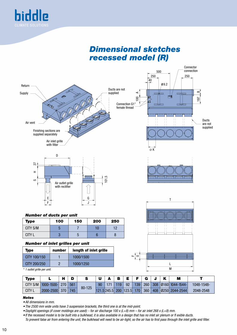
Dimensional sketchesrecessed model (R)
Notes• All dimensions in mm.• The 2500 mm wide units have 3 suspension brackets, the third one is at the mid-point.• Daylight openings (if cover moldings are used): - for air discharge 100 x (L+8) mm – for air inlet 268 x (L+8) mm.• If the recessed model is to be built into a bulkhead, it is also available in a design that has no inlet air plenum or fl exible ducts. To prevent false air from entering the unit, the bulkhead will need to be air-tight, so the air has to first pass through the inlet grille and filter.
* 1 outlet grille per unit.
Return
Supply
Air vent
Air inlet grillewith filter
Air outlet grillewith rectifier
Finishing sections aresupplied separately
B19
7
Ducts are notsupplied
Connection G1”female thread
500250 250
40ø 9.2
Connectorconnection
Ductsare notsupplied
ø K
T
L
M
F U
D
100
A
101,
5
H27
S
EF J
G
Type 100 150 200 250
CITY S/M 5 7 10 12
CITY L 3 5 6 8
Type number length of inlet grille
CITY 100/150 1 1000/1500
CITY 200/250 2 1000/1250
Number of ducts per unit
Number of inlet grilles per unit
Type L H D S U A B E F G J K M T
CITY S/M 1000-1500- 270 561 90 171 119 92 139 260 308 Ø160 1044-1544- 1048-1548-
CITY L 2000-2500 370 745 121.5 245.5 200 123.5 170 360 408 Ø250 2044-2544 2048-254880-125

11
Dimensional sketchescassette model (C)
Notes• All dimensions in mm.• The 2500 mm wide units have 3 suspension brackets, the third one is at the mid-point.• Daylight openings if cover moldings are used in a suspended ceiling: (L+8) x 829 mm.
* 1 outlet grille per unit
Return
Supply
Air vent
Air inlet grillewith filter
Air outlet grille with rectifier
Finishing section,width 4 mmFinishing sections
are suppliedseperately
B19
7
250 25040
ø 9.2
Connectorconnection
L
L
H27
D
E U
FG
100
A
Type number length of inlet grille
CITY 100/150 1 1000/1500
CITY 200/250 2 1000/1250
Number of inlet grilles per unit
Eye bolt M6
Connection G1” femalethread
D
Type L H D U A B E F G
CITY S/M 1000-1500- 270 821 93 171 119 150 411 260
CITY L 2000-2500 370 1105 124.5 245.5 200 181.5 563.5 360

SpecificationsCasing
The casing is made of zinc-plated sheet steel, extra strengthened to minimise vibration, and it has an inspection panel in the bottom. The plastic air inlet grilles have a perforated zinc-plated steel insert. The unit is as standard available in the following colours: a combination of white (RAL 9016) and greyish white (RAL 9002), and in aluminium colour (RAL 9006). Other RAL colours are available on request.
Motor / fan assembly Two or more (depending on type) dual-inlet, vibration-free centrifugal fans. Each fan is driven by a suspended rotor motor on ball bearings. The fan casing and the impeller are made of zinc coated plate steel. The motor is manufactured according to EN 60-335-1, protection class IP44 (CITY S) or IP54 (CITY M/L), and insulation class F.The motors are, as a standard, fitted with thermal contacts. These thermal contacts will break the circuit of the motor when the maximum permissible motor temperature is exceeded.
Coil The 2-row LPHW heating coil is made up of 3/8" copper pipes and aluminium fins. The water supply connections are G1" female thread. The test pressure is 30 bars and the operating pressure is 16 bars max. at 120 °C. The electric heating coil is composed of aluminium fins. The coil is controlled by the electronic control unit, and is fitted with overload protection. When the unit is switched off, the fans will continue to rotate until the fins have cooled off sufficiently.
• ISO 9001• ISO 14001
Subject to change
CITY.CEE-en-2014-10-PDF•14102854
Biddle GmbHEmil-Hoffmann-Strasse 55-5950996 CologneGermanyT +49 2236 9690-12F +49 2236 9690-10E [email protected] www.biddle.info