Embed Size (px)
Citation preview

SERVICE MANUAL
HORIZONTAL CRANKSHAFT
COMMAND CH11-16

Contents
Section 1. Safety and General Information ............................................................................
Section 2. Tools & Aids ............................................................................................................
Section 3. Troubleshooting .....................................................................................................
Section 4. Air Cleaner and Air Intake System ........................................................................
Section 5. Fuel System and Governor ....................................................................................
Section 6. Lubrication System ................................................................................................
Section 7. Retractable Starter .................................................................................................
Section 8. Electrical System and Components .....................................................................
Section 9. Disassembly ...........................................................................................................
Section 10. Inspection and Reconditioning ...........................................................................
Section 11. Reassembly...........................................................................................................
1
2
3
4
5
6
7
8
9
10
11

1.1
Section 1Safety and General Information
1
Safety Precautions
To ensure safe operation please read the following statements and understand their meaning. Alsorefer to your equipment manufacturer's manual for other important safety information. This manualcontains safety precautions which are explained below. Please read carefully.
WARNINGWarning is used to indicate the presence of a hazard that can cause severe personal injury, death,or substantial property damage if the warning is ignored.
CAUTIONCaution is used to indicate the presence of a hazard that will or can cause minor personal injury orproperty damage if the caution is ignored.
NOTENote is used to notify people of installation, operation, or maintenance information that is importantbut not hazard-related.
For Your Safety!These precautions should be followed at all times. Failure to follow these precautions could result in injury toyourself and others.
Rotating Parts!Keep hands, feet, hair, and clothingaway from all moving parts to preventinjury. Never operate the engine withcovers, shrouds, or guards removed.
Hot Parts!Engine components can get extremelyhot from operation. To prevent severeburns, do not touch these areas whilethe engine is running - or immediatelyafter it is turned off. Never operate theengine with heat shields or guardsremoved.
Accidental Starts!Disabling engine. Accidentalstarting can cause severe injury ordeath. Before working on the engine orequipment, disable the engine asfollows: 1) Disconnect the spark pluglead(s). 2) Disconnect negative (-)battery cable from battery.
Accidental Starts can cause severe
injury or death.
Disconnect and ground spark pluglead before servicing.
WARNING
Rotating Parts can cause severeinjury.
Stay away while engine is inoperation.
WARNING
Hot Parts can cause severe burns.
Do not touch engine while operatingor just after stopping.
WARNING
Section 1Safety and General Information

1.2
Section 1Safety and General Information
Lethal Exhaust Gases!Engine exhaust gases containpoisonous carbon monoxide. Carbonmonoxide is odorless, colorless, and cancause death if inhaled. Avoid inhalingexhaust fumes, and never run theengine in a closed building or confinedarea.
Explosive Gas!Batteries produce explosive hydrogengas while being charged. To prevent afire or explosion, charge batteries onlyin well ventilated areas. Keep sparks,open flames, and other sources ofignition away from the battery at alltimes. Keep batteries out of the reach ofchildren. Remove all jewelry whenservicing batteries.
Before disconnecting the negative(-) ground cable, make sure all switchesare OFF. If ON, a spark will occur atthe ground cable terminal which couldcause an explosion if hydrogen gas orgasoline vapors are present.
Spring Under Tension!Retractable starters contain a powerful,recoil spring that is under tension.Always wear safety goggles whenservicing retractable starters andcarefully follow instructions in theRetractable Starter Section 7 for relievingspring tension.
Explosive Fuel!Gasoline is extremely flammable andits vapors can explode if ignited. Storegasoline only in approved containers,in well ventilated, unoccupiedbuildings, away from sparks or flames.Do not fill the fuel tank while theengine is hot or running, since spilledfuel could ignite if it comes in contactwith hot parts or sparks from ignition.Do not start the engine near spilledfuel. Never use gasoline as a cleaningagent.
Flammable Solvents!Carburetor cleaners and solvents areextremely flammable. Keep sparks,flames, and other sources of ignitionaway from the area. Follow the cleanermanufacturer’s warnings andinstructions on its proper and safe use.Never use gasoline as a cleaning agent.
Explosive Fuel can cause fires andsevere burns.
Do not fill the fuel tank while theengine is hot or running.
WARNING
Carbon Monoxide can cause severe
nausea, fainting or death.Avoid inhaling exhaust fumes, andnever run the engine in a closedbuilding or confined area.
WARNING WARNING
Explosive Gas can cause fires andsevere acid burns.
Charge battery only in a wellventilated area. Keep sources ofignition away.
Cleaning Solvents can cause severeinjury or death.
Use only in well ventilated areasaway from ignition sources.
WARNING
Electrical Shock can cause injury.
Do not touch wires while engine isrunning.
CAUTION
Uncoiling Spring can cause severeinjury.
Wear safety goggles or faceprotection when servicingretractable starter.
WARNING
Electrical Shock!Never touch electrical wires orcomponents while the engine isrunning. They can be sources ofelectrical shock.

1.3
Section 1Safety and General Information
1
Engine Identification NumbersWhen ordering parts, or in any communicationinvolving an engine, always give the Model,Specification, and Serial Numbers, including lettersuffixes if any.
The engine identification numbers appear on a decal,or decals, affixed to the engine shrouding. See Figure1-1. An explanation of these numbers is shown inFigure 1-2.
Figure 1-2. Explanation of Engine Identification Numbers.
Figure 1-1. Engine Identification Decal Location.
B. Spec. No.Engine Model CodeCode Model16 CH1119 CH12.522 CH1318 CH1444 CH1545 CH16
Variation ofBasic Engine
1903
A. Model No.Command EngineHorizontal CrankshaftHorsepower11 = 11 HP12.5 = 12.5 HP13 = 13 HP14 = 14 HP15 = 15 HP16 = 16 HP
Version CodeS = Electric StartT = Retractable StartST = Electric/Retractable StartGT = Generator Application/Retractable StartGS = Generator Application/Electric StartPT = Pump/Retractable StartRT = Gear Reduction/Retractable Start
C H 12.5 ST
Factory CodeC. Serial No.
Year Manufactured CodeCode Year20 199021 199122 199223 199324 199425 199526 199627 199728 1998
2005810334
MODEL NO.SPEC. NO.SERIAL NO.REFER TO OWNER'S MANUAL FORSAFETY, MAINTENANCE SPECSAND ADJUSTMENTS. FOR SALESAND SERVICE IN US/CANADACALL: 1-800-544-2444.
www.kohlerengines.com
KOHLER CO. KOHLER, WI USA
CH12.5ST1903 2005810334
ABC
IdentificationDecal
Code Year29 199930 200031 200132 200233 200334 200435 200536 200637 2007

1.4
Section 1Safety and General Information
Oil RecommendationsUsing the proper type and weight of oil in thecrankcase is extremely important. So is checking oildaily and changing oil regularly. Failure to use thecorrect oil, or using dirty oil, causes premature enginewear and failure.
Oil TypeUse high-quality detergent oil of API (AmericanPetroleum Institute) service class SG, SH, SJ, orhigher. Select the viscosity based on the airtemperature at the time of operation as shown in thefollowing table.
NOTE: Using other than service class SG, SH, SJ, orhigher oil or extending oil change intervalslonger than recommended can cause enginedamage.
NOTE: Synthetic oils meeting the listedclassifications may be used with oil changesperformed at the recommended intervals.However to allow piston rings to properlyseat, a new or rebuilt engine should beoperated for at least 50 hours using standardpetroleum based oil before switching tosynthetic oil.
A logo or symbol on oil containers identifies the APIservice class and SAE viscosity grade. See Figure 1-3.
Fuel Recommendations
WARNING: Explosive Fuel!Gasoline is extremely flammable and its vapors can explode ifignited. Store gasoline only in approved containers, in wellventilated, unoccupied buildings, away from sparks or flames.Do not fill the fuel tank while the engine is hot or running,since spilled fuel could ignite if it comes in contact with hotparts or sparks from ignition. Do not start the engine nearspilled fuel. Never use gasoline as a cleaning agent.
General RecommendationsPurchase gasoline in small quantities and store inclean, approved containers. A container with acapacity of 2 gallons or less with a pouring spout isrecommended. Such a container is easier to handleand helps eliminate spilling during refueling.
Do not use gasoline left over from the previous season,to minimize gum deposits in your fuel system and toensure easy starting.
Do not add oil to the gasoline.
Do not overfill the fuel tank. Leave room for the fuel toexpand.
Fuel TypeFor best results, use only clean, fresh, unleadedgasoline with a pump sticker octane rating of 87 orhigher. In countries using the Research method, itshould be 90 octane minimum.
Unleaded gasoline is recommended, as it leaves lesscombustion chamber deposits. Leaded gasoline maybe used in areas where unleaded is not available andexhaust emissions are not regulated. Be awarehowever, that the cylinder head will require morefrequent service.
Gasoline/Alcohol blendsGasohol (up to 10% ethyl alcohol, 90% unleadedgasoline by volume) is approved as a fuel for Kohlerengines. Other gasoline/alcohol blends are notapproved.
Gasoline/Ether blendsMethyl Tertiary Butyl Ether (MTBE) and unleadedgasoline blends (up to maximum of 15% MTBE byvolume) are approved as a fuel for Kohler engines.Other gasoline/ether blends are not approved.
Figure 1-3. Oil Container Logo.
Refer to Section 6 Lubrication System for detailed oilcheck, oil change, and oil filter procedures.
*Use of synthetic oil having 5W-20 or 5W-30 rating isacceptable, up to 4°C (40°F).
**Synthetic oils will provide better starting inextreme cold below 23°C (-10°F).
** *

1.5
Section 1Safety and General Information
1
Periodic Maintenance
1Perform these maintenance procedures more frequently under extremely dusty, dirty conditions.2Only required for Denso starters. Not necessary on Delco starters. Have a Kohler Engine Service Dealer perform this service.
StorageIf the engine will be out of service for two months ormore, use the following storage procedure:
1. Clean the exterior surfaces of the engine.
2. Change the oil and oil filter while the engine isstill warm from operation. See Change Oil andOil Filter in Section 6.
3. The fuel system must be completely emptied, orthe gasoline must be treated with a stabilizer toprevent deterioration. If you choose to use astabilizer, follow the manufacturersrecommendations, and add the correct amountfor the capacity of the fuel system. Fill the fueltank with clean, fresh gasoline. Run the enginefor 2-3 minutes to get stabilized fuel into thecarburetor.
To empty the system, run the engine until thetank and system are empty.
4. Remove the spark plug. Add one tablespoon ofengine oil into the spark plug hole. Install theplug, but do not connect the plug lead. Crank theengine two or three revolutions.
5. Remove the spark plug. Cover the spark plughole with your thumb, and turn the engine overuntil the piston is at the top of its stroke.(Pressure against thumb is greatest.) Reinstallthe plug, but do not connect the plug lead.
6. Store the engine in a clean, dry place.
Maintenance ScheduleThe following required maintenance procedures should be performed at the frequency stated in the table andshould also be included as part of any seasonal tune-up.
WARNING: Accidental Starts!Disabling engine. Accidental starting can cause severe injury or death. Before working on the engine or equipment,disable the engine as follows: 1) Disconnect the spark plug lead(s). 2) Disconnect negative (-) battery cable from battery.
Frequency Maintenance Required Refer to:
• Fill fuel tank.• Check oil level.• Check air cleaner for dirty1, loose, or damaged parts.• Check air intake and cooling areas, clean as necessary1.
Daily or BeforeStarting Engine
Section 5Section 6Section 4Section 4
• Service precleaner element1.Every 25 Hours Section 4
• Replace air cleaner element1.• Change oil1.• Remove cooling shrouds and clean cooling areas1.
Every100 Hours
Section 4Section 6Section 4
• Change oil filter.• Check spark plug condition and gap.• Replace fuel filter.
Every200 Hours
Section 6Section 8Section 5
Annually or Every500 Hours
• Have bendix starter drive serviced2.• Have solenoid shift starter disassembled and cleaned2.
Section 8Section 8
Every 50 Hours • Check oil level in gear reduction unit. Section 6

1.6
Section 1Safety and General Information
Figure 1-4. Typical Engine Dimensions.
Dimensions in millimeters.Inch equivalents shown in ( ).

1.7
Section 1Safety and General Information
1
General Specifications1
Power (@ 3600 RPM, exceeds SAE J1940 HP standards)CH11 .......................................................................................................... 8.20 kW (11 HP)CH12.5 ....................................................................................................... 9.33 kW (12.5 HP)CH13 .......................................................................................................... 9.75 kW (13 HP)CH14 .......................................................................................................... 10.50 kW (14 HP)CH15 .......................................................................................................... 11.20 kW (15 HP)CH16 .......................................................................................................... 11.90 kW (16 HP)
Peak Torque (@ RPM indicated)CH11 (@ 2400 RPM) ................................................................................. 26.7 N·m (19.7 ft. lb)CH12.5 (@ 2500 RPM) .............................................................................. 27.8 N·m (20.5 ft. lb)CH13 (@ 2400 RPM) ................................................................................. 28.8 N·m (21.2 ft. lb)CH14 (@ 2500 RPM) ................................................................................. 27.8 N·m (21.3 ft. lb)CH15 (@ 2400 RPM) ................................................................................. 34.3 N·m (25.3 ft. lb)CH16 (@ 2400 RPM) ................................................................................. 33.9 N·m (25.0 ft. lb)
BoreCH11, CH12.5, CH13, CH14 .................................................................... 87 mm (3.43 in.)CH15, CH16 .............................................................................................. 90 mm (3.54 in.)
Stroke ................................................................................................................ 67 mm (2.64 in.)
DisplacementCH11, CH12.5, CH13, CH14 .................................................................... 398 cc (24.3 cu. in.³)CH15, CH16 .............................................................................................. 426 cc (26.0 cu. in.³)
Compression Ratio ......................................................................................... 8.5:1
Weight .............................................................................................................. 40 kg (88.3 lb.)
Max. Oil Capacity (w/filter) .......................................................................... 1.9 L (2.0 qt.)
Lubrication ...................................................................................................... full pressure w/full flow filter
Air CleanerBase Nut Torque .............................................................................................. 9.9 N·m (88 in. lb.)
Angle of Operation - Maximum (at full oil level)Intermittent - All Directions ......................................................................... 35°Continuous - All Directions .......................................................................... 25°
Balance ShaftEnd Play (Free) ................................................................................................ 0.0575/0.3625 mm (0.0023/0.0137 in.)Running Clearance ......................................................................................... 0.025/0.1520 mm (0.0009/0.0059 in.)
Bore I.D.New ........................................................................................................... 20.000/20.025 mm (0.7874/0.7884 in.)Max. Wear Limit ...................................................................................... 20.038 mm (0.7889 in.)
Balance Shaft Bearing Surface O.D.New ........................................................................................................... 19.962/19.975 mm (0.7859/0.7864 in.)Max. Wear Limit ...................................................................................... 19.959 mm (0.7858 in.)
1Values are in Metric units. Values in parentheses are English equivalents. Lubricate threads with engine oil prior toassembly.

1.8
Section 1Safety and General Information
CamshaftEnd Play (Free) ................................................................................................ 0.0875/0.3925 mm (0.0034/0.0154 in.)End Play (with Shims) ................................................................................... 0.0762/0.1270 mm (0.0030/0.0050 in.)Running Clearance ......................................................................................... 0.025/0.1050 mm (0.00098/0.0041 in.)
Bore I.D.New ........................................................................................................... 20.000/20.025 mm (0.7874/0.7884 in.)Max. Wear Limit ...................................................................................... 20.038 mm (0.7889 in.)
Camshaft Bearing Surface O.D.New ........................................................................................................... 19.962/19.975 mm (0.7859/0.7864 in.)Max. Wear Limit ...................................................................................... 19.959 mm (0.7858 in.)
CarburetorFuel Bowl Nut Torque .................................................................................... 5.1-6.2 N·m (45-55 in. lb.)
ChargingStator Mounting Screw Torque .................................................................... 6.2 N·m (55 in. lb.)
Closure PlateOil Filter Tightening ....................................................................................... 3/4-1 turn after gasket contacts.
Oil Filter Adapter Fastener Torque .............................................................. 11.3 N·m (100 in. lb.)
Oil Filter Drain Plug (1/8" NPT) Torque ....................................................... 7.3-9.0 N·m (65-80 in. lb.)
Closure Plate Fastener Torque ...................................................................... 24.4 N·m (216 in. lb.)
Oil Sentry Pressure Switch Torque .............................................................. 6.8 N·m (60 in. lb.)
Oil Pump Cover Fastener Torque² ............................................................... 4.0,6.2 N·m (35,55 in. lb.)
Connecting RodCap Fastener Torque
6 mm straight shank bolt ....................................................................... 11.3 N·m (100 in. lb.)8 mm straight shank bolt ....................................................................... 22.6 N·m (200 in. lb.)8 mm step-down type bolt .................................................................... 14.7 N·m (130 in. lb.)
Connecting Rod-to-Crankpin Running Clearance at 21°C (70°F)New ........................................................................................................... 0.030/0.055 mm (0.0012/0.0022 in.)Max. Wear Limit ...................................................................................... 0.07 mm (0.0025 in.)
Connecting Rod-to-Crankpin Side Clearance ............................................ 0.18/0.41 mm (0.007/0.016 in.)
Connecting Rod-to-Piston Pin Running Clearance 21°C (70°F) ............... 0.015/0.028 mm (0.0006/0.0011 in.)
Piston Pin End I.D.New ........................................................................................................... 19.015/19.023 mm (0.7486/0.7489 in.)Max. Wear Limit ...................................................................................... 19.036 mm (0.7495 in.)
CrankcaseGovernor Cross Shaft Bore I.D.
New ........................................................................................................... 6.025/6.050 mm (0.2372/0.2382 in.)Max. Wear Limit ...................................................................................... 6.063 mm (0.2387 in.)
2For self-tapping (thread-forming) fasteners, the higher torque value is for installation into a new cored (non-threaded) hole. The lower torque value is for installation into a used or threaded hole.

1.9
Section 1Safety and General Information
1
CrankshaftEnd Play (Free) ................................................................................................ 0.0575/0.4925 mm (0.0022/0.0193 in.)End Play (Thrust Bearing with Shims) ....................................................... 0.0500/0.5300 mm (0.0019/0.0208 in.)
Crankshaft Bearing I.D. (In Crankcase)Sleeve Bearing (Installed) - New ........................................................... 44.965/45.003 mm (1.7703/1.7718 in.)Sleeve Bearing - Max. Wear Limit ......................................................... 45.016 mm (1.7723 in.)Parent Material (No Sleeve Bearing) - New ........................................ 44.965/44.990 mm (1.7703/1.7713 in.)Parent Material (No Sleeve Bearing) - Max. Wear Limit ................... 45.003 mm (1.7718 in.)
Crankshaft to Bearing Running Clearance - NewSleeve Bearing .......................................................................................... 0.030/0.090 mm (0.0011/0.0035 in.)Parent Material (No Sleeve Bearing) .................................................... 0.030/0.077 mm (0.0011/0.0030 in.)
Crankshaft Bearing I.D. (In Closure Plate)Sleeve Bearing (Installed) - New ........................................................... 41.960/42.035 mm (1.6519/1.6549 in.)Sleeve Bearing - Max. Wear Limit ......................................................... 42.048 mm (1.6554 in.)Parent Material (No Sleeve Bearing) - New ........................................ 41.965/42.003 mm (1.6521/1.6536 in.)Parent Material (No Sleeve Bearing) - Max. Wear Limit ................... 42.015 mm (1.6541 in.)
Crankshaft Bore (In Closure Plate) to Crankshaft Running Clearance - NewSleeve Bearing .......................................................................................... 0.025/0.1200 mm (0.00098/0.00472 in.)Parent Material (No Sleeve Bearing) .................................................... 0.030/0.0880 mm (0.0011/0.0034 in.)
Flywheel End Main Bearing JournalO.D. - New ................................................................................................ 44.913/44.935 mm (1.7682/1.7691 in.)O.D. - Max. Wear Limit ........................................................................... 44.84 mm (1.765 in.)Max. Taper ................................................................................................ 0.022 mm (0.0009 in.)Max. Out-of-Round ................................................................................. 0.025 mm (0.0010 in.)
Closure Plate End Main Bearing JournalO.D. - New ................................................................................................ 41.915/41.935 mm (1.6502/1.6510 in.)O.D. - Max. Wear Limit ........................................................................... 41.86 mm (1.648 in.)Max. Taper ................................................................................................ 0.020 mm (0.0008 in.)Max. Out-of-Round ................................................................................. 0.025 mm (0.0010 in.)
Connecting Rod JournalO.D. - New ................................................................................................ 38.958/38.970 mm (1.5338/1.5343 in.)O.D. - Max. Wear Limit ........................................................................... 38.94 mm (1.5328 in.)Max. Taper ................................................................................................ 0.012 mm (0.0005 in.)Max. Out-of-Round ................................................................................. 0.025 mm (0.0010 in.)
Crankshaft T.I.R.PTO End, Crank in Engine ...................................................................... 0.304 mm (0.012 in.)Entire Crank, in V-Blocks ....................................................................... 0.10 mm (0.0039 in.)
Cylinder BoreCylinder Bore I.D.
NewCH11-14 .................................................................................................. 87.000/87.025 mm (3.4252/3.4262 in.)CH15, CH16 ............................................................................................ 90.000/90.025 mm (3.5433/3.5442 in.)
Max. Wear LimitCH11-14 .................................................................................................. 87.063 mm (3.4277 in.)CH15, CH16 ............................................................................................ 90.063 mm (3.5457 in.)

1.10
Section 1Safety and General Information
Cylinder Bore I.D. cont'd.Max. Out-of-RoundCH11-14 .................................................................................................. 0.12 mm (0.0047 in.)CH15, CH16 ............................................................................................ 0.12 mm (0.0047 in.)
Max. TaperCH11-14 .................................................................................................. 0.05 mm (0.0020 in.)CH15, CH16 ............................................................................................ 0.05 mm (0.0020 in.)
Cylinder HeadCylinder Head Fastener Torque (torque in 2 increments) ........................ 24,48.9 N·m (18,36 ft. lb.)
Max. Out-of-Flatness ...................................................................................... 0.076 mm (0.003 in.)
Rocker Pedestal Fastener Torque ................................................................. 9.9 N·m (88 in. lb.)
Electric StarterThru Bolt Torque
UTE/Johnson Electric, Eaton (Inertia Drive) ..................................... 4.5-5.7 N·m (40-50 in. lb.)Nippondenso (Solenoid Shift) ............................................................ 4.5-7.5 N·m (40-84 in. lb.)Delco-Remy (Solenoid Shift) ............................................................... 5.6-9.0 N·m (49-79 in. lb)
Drive Pinion Fastener Torque (some Inertia Drive Starters) .................... 15.3 N·m (135 in. lb.)
Brush Holder Mounting Screw TorqueDelco-Remy Starter ............................................................................. 2.5-3.3 N·m (22-29 in. lb.)
Solenoid (Starter)Mounting Hardware Torque
Nippondenso Starter .......................................................................... 6.0-9.0 N·m (53-79 in. lb.)Delco-Remy Starter ............................................................................. 4.0-6.0 N·m (35-53 in. lb.)
Nut, Positive (+) Brush Lead TorqueNippondenso Starter .......................................................................... 8.0-12.0 N·m (71-106 in. lb)Delco-Remy Starter ............................................................................. 6.0-9.0 N·m (53-79 in. lb.)
Fan/FlywheelFan Fastener Torque ....................................................................................... 9.9 N·m (88 in. lb.)
Flywheel Retaining Screw Torque ............................................................... 66.4 N·m (49 ft. lb.)
Fuel PumpFuel Pump/Cover Fastener Screw Torque .................................................. 9.0 N·m (80 in. lb.) into new holes
4.2-5.1 N·m (37-45 in. lb.) into used holesFuel TankFuel Tank Fastener Torque ............................................................................. 7.3 N·m (65 in. lb.)
GovernorGovernor Cross Shaft to Crankcase Running Clearance ......................... 0.025/0.075 mm (0.0010/0.0030 in.)
Governor Cross Shaft O.D.New ........................................................................................................... 5.975/6.000 mm (0.2352/0.2362 in.)Max. Wear Limit ...................................................................................... 5.962 mm (0.2347 in.)
Governor Gear Shaft-to-Governor Gear Running Clearance ................. 0.015/0.140 mm (0.0006/0.0055 in.)
Governor Gear Shaft O.D.New ........................................................................................................... 5.990/6.000 mm (0.2358/0.2362 in.)Max. Wear Limit ...................................................................................... 5.977 mm (0.2353 in.)

1.11
Section 1Safety and General Information
1
IgnitionSpark Plug Type (Champion® or equivalent) ............................................. RC12YC or Platinum 3071
Spark Plug GapCH11-15 .................................................................................................... 1.02 mm (0.040 in.)CH16 .......................................................................................................... 0.76 mm (0.030 in.)
Spark Plug Torque .......................................................................................... 38.0-43.4 N·m (28-32 ft. lb.)
Ignition Module Air Gap ............................................................................... 0.203/0.305 mm (0.008/0.012 in.)
Ignition Module Fastener Torque ................................................................. 4.0 N·m (35 in. lb.) into new holes6.2 N·m (55 in. lb.) into used holes
MufflerMuffler Retaining Nuts .................................................................................. 24.4 N·m (216 in. lb.)
Piston, Piston Rings, and Piston PinPiston-to-Piston Pin (selective fit) ............................................................... 0.006/0.017 mm (0.0002/0.0007 in.)
Piston Pin Bore I.D.New ........................................................................................................... 19.006/19.012 mm (0.7483/0.7485 in.)Max. Wear Limit ...................................................................................... 19.025 mm (0.7490 in.)
Piston Pin O.D.New ........................................................................................................... 18.995/19.000 mm (0.7478/0.7480 in.)Max. Wear Limit ...................................................................................... 18.994 mm (0.74779 in.)
Top Compression Ring-to-Groove Side ClearanceCH11-14 .................................................................................................... 0.040/0.105 mm (0.0016/0.0041 in.)CH15, CH16 .............................................................................................. 0.060/0.105 mm (0.0023/0.0041 in.)
Middle Compression Ring-to-Groove Side ClearanceCH11-14 .................................................................................................... 0.040/0.072 mm (0.0016/0.0028 in.)CH15, CH16 .............................................................................................. 0.040/0.085 mm (0.0015/0.0002 in.)
Oil Control Ring-to-Groove Side ClearanceCH11-14 .................................................................................................... 0.551/0.675 mm (0.0217/0.0266 in.)CH15, CH16 .............................................................................................. 0.176/0.026 (0.0069/0.0010 in.)
Top and Center Compression Ring End GapNew Bore
CH11-14 ................................................................................................ 0.3/0.5 mm (0.012/0.020 in.)CH15, CH16 .......................................................................................... 0.27/0.51 mm (0.010/0.020 in.)
Used Bore (Max.) ...................................................................................... 0.77 mm (0.030 in.)
Piston Thrust Face O.D.New
CH11-143 ............................................................................................... 86.941/86.959 mm (3.4229/3.4236 in.)CH15, CH164 ......................................................................................... 89.951/89.969 mm (3.5413/3.5420 in.)
Max. Wear LimitCH11-14 ................................................................................................ 86.814 mm (3.4179 in.)CH15, CH16 .......................................................................................... 89.824 mm (3.5363 in.)
3Measure 6 mm (0.236 in.) above the bottom of the piston skirt at right angles to the piston pin.4Measure 8 mm (0.314 in.) above the bottom of the piston skirt at right angles to the piston pin.

1.12
Section 1Safety and General Information
Piston Thrust Face-to-Cylinder Bore Running Clearance - NewCH11-14 .................................................................................................... 0.041/0.044 mm (0.0016/0.0017 in.)CH15, CH16 .............................................................................................. 0.031/0.043 mm (0.0012/0.0016 in.)
Retractable StarterCenter Screw Torque ...................................................................................... 7.4-8.5 N·m (65-75 in. lb.)
Throttle/Choke ControlsGovernor Control Lever Fastener Torque .................................................. 9.9 N·m (88 in. lb.)
Speed Control Bracket Assembly Fastener Torque² .................................. 7.3-10.7 N·m (65-95 in. lb.)
Valve Cover/Rocker ArmsValve Cover Fastener Torque² ...................................................................... 7.3-10.7 N·m (65-95 in. lb.)
Rocker Arm I.D.New ........................................................................................................... 15.837/16.127 mm (0.63/0.64 in.)Max. Wear Limit ...................................................................................... 16.13 mm (0.640 in.)
Rocker Shaft O.D.New ........................................................................................................... 15.90/15.85 mm (0.63 in.)Max. Wear Limit ...................................................................................... 15.727 mm (0.619 in.)
Valves and Valve LiftersHydraulic Valve Lifter to Crankcase Running Clearance ........................ 0.0124/0.0501 mm (0.0005/0.0020 in.)
Intake Valve Stem-to-Valve Guide Running Clearance ........................... 0.038/0.076 mm (0.0015/0.0030 in.)
Exhaust Valve Stem-to-Valve Guide Running Clearance ........................ 0.050/0.088 mm (0.0020/0.0035 in.)
Intake Valve Guide I.D.New ........................................................................................................... 7.038/7.058 mm (0.2771/0.2779 in.)Max. Wear Limit ...................................................................................... 7.134 mm (0.2809 in.)
Exhaust Valve Guide I.D.New ........................................................................................................... 7.038/7.058 mm (0.2771/0.2779 in.)Max. Wear Limit ...................................................................................... 7.159 mm (0.2819 in.)
Valve Guide Reamer SizeSTD ............................................................................................................. 7.048 mm (0.2775 in.)0.25 mm O.S. ............................................................................................. 7.298 mm (0.2873 in.)
Intake Valve Minimum Lift ........................................................................... 8.96 mm (0.353 in.)
Exhaust Valve Minimum Lift ....................................................................... 9.14 mm (0.360 in.)
Nominal Valve Seat Angle ............................................................................ 45°
2For self-tapping (thread-forming) fasteners, the higher torque value is for installation into a new cored (non-threaded) hole. The lower torque value is for installation into a used or threaded hole.

1.13
Section 1Safety and General Information
1
General Torque Values
Metric Fastener Torque Recommendations for Standard Applications
SizeM4 1.2 (11) 1.7 (15) 2.9 (26) 4.1 (36) 5.0 (44) 2.0 (18)M5 2.5 (22) 3.2 (28) 5.8 (51) 8.1 (72) 9.7 (86) 4.0 (35)M6 4.3 (38) 5.7 (50) 9.9 (88) 14.0 (124) 16.5 (146) 6.8 (60)M8 10.5 (93) 13.6 (120) 24.4 (216) 33.9 (300) 40.7 (360) 17.0 (150)
Tightening Torque: N·m (ft. lb.) + or - 10%
Property Class
M10 21.7 (16) 27.1 (20) 47.5 (35) 66.4 (49) 81.4 (60) 33.9 (25)M12 36.6 (27) 47.5 (35) 82.7 (61) 116.6 (86) 139.7 (103) 61.0 (45)M14 58.3 (43) 76.4 (55) 131.5 (97) 184.4 (136) 219.7 (162) 94.9 (70)
NoncriticalFasteners
Into Aluminum
NoncriticalFasteners
Into Aluminum
Tightening Torque: N·m (in. lb.) + or - 10%Property Class
N·m = in. lb. x 0.113N·m = ft. lb. x 1.356in. lb. = N·m x 8.85ft. lb. = N·m x 0.737
TorqueConversions
4.8 5.8 8.8 10.9 12.9
4.8 5.8 8.8 10.9 12.9
Oil Drain Plugs Tightening Torque: N·m (English Equiv.)Size1/8" NPT1/4"3/8"1/2"3/4"X-708-1
Into Cast Iron–
17.0 (150 in. lb.)20.3 (180 in. lb.)27.1 (20 ft. lb.)33.9 (25 ft. lb.)
27.1/33.9 (20/25 ft. lb.)
Into Aluminum4.5 (40 in. lb.)
11.3 (100 in. lb.)13.6 (120 in. lb.)17.6 (13 ft. lb.)21.7 (16 ft. lb.)
27.1/33.9 (20/25 ft. lb.)

2.1
Section 2Tools & Aids
2
Section 2Tools & Aids
Certain quality tools are designed to help you perform specific disassembly, repair, and reassembly procedures.By using tools designed for the job, you can properly service engines easier, faster, and safer! In addition, you’llincrease your service capabilities and customer satisfaction by decreasing engine downtime.
Here is the list of tools and their source.
Separate Tool Suppliers:Kohler ToolsContact your sourceof supply.
SE Tools415 Howard St.Lapeer, MI 48446Phone 810-664-2981Toll Free 800-664-2981Fax 810-664-8181
Design Technology Inc.768 Burr Oak DriveWestmont, IL 60559Phone 630-920-1300
slooT
noitpircseD .oNtraP/ecruoS
)seireSM&K(looTgnimiTraeGecnalaB.enignegnilbmessanehwnoitisopdemitnisraegecnalabdlohoT
S-6055452relhoK)753-YylremroF(
etalPyalpdnEtfahsmaC.yalpdnetfahsmacgnikcehcroF
50428-RLKslooTES
retseTnwodkaeLrednilyC.nrowerasevlavro,sgnir,notsip,rednilycfidnanoitneternoitsubmocgnikcehcroF
S-5016752relhoK
erawtfoScitsongaiD)IFE(noitcejnIleuFcinortcelE.CPpotkseDropotpaLhtiwesU
S-3216752relhoK
IFE tiKecivreS.enigneIFEnapugnittesdnagnitoohselbuortroF
S-1016742relhoK
elbaliavAstnenopmoClaudividnIretseTerusserP
thgiLdioNretpadA°09
sreilPpmalCrekiteOeriWdeR,gulPedoCeriWeulB,gulPedoC
.cnIygolonhceTngiseD910-ITD120-ITD320-ITD520-ITD720-ITD920-ITD
)seireSSC(looTgnidloHleehwylF 70428-RLKslooTES
relluPleehwylF.enignemorfleehwylfevomeroT
80428-RLKslooTES
hcnerWpartSleehwylF.lavomergnirudleehwylfdlohoT
90428-RLKslooTES

2.2
Section 2Tools & Aids
).tnoc(slooT
noitpircseD .oNtraP/ecruoS
looTretfiLevlaVciluardyH.sretfilciluardyhllatsnidnaevomeroT
S-8316752relhoK
retseTmetsySnoitingI.DCtpecxe,smetsysllanotuptuognitsetroF
.metsysnoitingi)DC(egrahcsideviticapacnotuptuognitsetroFS-1055452relhoKS-2055442relhoK
)seireSM&K(hcnerWtesffO.stungniniaterlerrabrednilycllatsnierdnaevomeroT
01428-RLKslooTES
tiKtseTerusserPliO.erusserplioyfirevdnatsetoT
S-6016752relhoK
)tnerructlov021(retseTrotalugeR-reifitceR)tnerructlov042(retseTrotalugeR-reifitceR
.srotaluger-reifitcertsetotdesU
S-0216752relhoKS-1416752relhoK
elbaliavAstnenopmoClaudividnIssenraHtseTrotalugeRORP-SC
edoiDhtiwssenraHtseTrotalugeRlaicepS
.cnIygolonhceTngiseD130-ITD330-ITD
retseT)MAS(eludoMecnavdAkrapSKRAPS-TRAMShtiwsenigneno)MASDdnaMASA(MASehttsetoT
.™
S-0416752relhoK
)tfihSdioneloS(looTgnidloHhsurBretratS.gnicivresgnirudsehsurbdlohoT
61428-RLKslooTES
)evirDaitrenI(looTgniRgniniateRretratS.)sretratsOCSAFgnidulcxe(sgnirgniniaterevirdllatsnierdnaevomeroT
S-8116752relhoK
)sretratSllA(tiKgnicivreSretratS.sehsurbdnasgnirgniniaterevirdllatsnierdnaevomeroT
11428-RLKslooTES
elbaliavAtnenopmoClaudividnI)tfihSdioneloS(looTgnidloHhsurBretratS
61428-RLKslooTES
)evitcudnIlatigiD(retemohcaT.enignenafo)MPR(deepsgnitarepognikcehcroF
.cnIygolonhceTngiseD011-ITD
retseTerusserP/muucaV.retemonamretawaotevitanretlA
S-2216752relhoK
)seireSM&K(remaeRediuGevlaV.noitallatsniretfasediugevlavgnizisroF
31428-RLKslooTES
)CHO,dnammoC,sigeA,egaruoC(tiKecivreSediuGevlaV.sediugeulavnrowgnicivresroF
51428-RLKslooTES

2.3
Section 2Tools & Aids
2
sdiA
noitpircseD .oNtraP/ecruoS
tnacirbuLtfahsmaC )316ZZrapslaV( S-4175352relhoK
esaerGcirtceleiD )166GdraugavoN/EG( S-1175352relhoK
esaerGcirtceleiD )orP-leF( leS-irbuL
tnacirbuLevirDretratScirtcelE )evirDaitrenI( S-1075325relhoK
tnacirbuLevirDretratScirtcelE )tfihSdioneloS( S-2075325relhoK
tnalaeSenociliSVTRetitcoL ® .resnepsidlosoreazo4niydoByvaeH0095
.esurofdevorppaera,detsilesohtsahcus,stnalaesVTRtnatsiserlio,desab-emixoylnOetitcoL ® .scitsiretcarahcgnilaestsebrofdednemmocerera0195ro0095.soN
etitcoL ® 0195etitcoL ® 895kcalBartlUetitcoL ® 785eulBartlUetitcoL ® reppoCartlU
S-7079552relhoK
tnacirbuLevirDenilpS S-2175352relhoK

2.4
Section 2Tools & Aids
Special Tools You Can Make
Flywheel Holding ToolA flywheel holding tool can be made out of an oldjunk flywheel ring gear as shown in Figure 2-1, andused in place of a strap wrench.
1. Using an abrasive cut-off wheel, cut out a sixtooth segment of the ring gear as shown.
2. Grind off any burrs or sharp edges.
3. Invert the segment and place it between theignition bosses on the crankcase so that the toolteeth engage the flywheel ring gear teeth. Thebosses will lock the tool and flywheel inposition for loosening, tightening or removingwith a puller.
Figure 2-1. Flywheel Holding Tool.
Rocker Arm/Crankshaft ToolA spanner wrench to lift the rocker arms or turn thecrankshaft may be made out of an old junk connectingrod.
1. Find a used connecting rod from a 10 HP orlarger engine. Remove and discard the rod cap.
2. Remove the studs of a Posi-Lock rod or grind offthe aligning steps of a Command rod, so the jointsurface is flat.
3. Find a 1 in. long capscrew with the correctthread size to match the threads in theconnecting rod.
4. Use a flat washer with the correct I.D. to slip onthe capscrew and approximately 1” O.D. (KohlerPart No. 12 468 05-S). Assemble the capscrewand washer to the joint surface of the rod, asshown in Figure 2-2.
Figure 2-2. Rocker Arm/Crankshaft Tool.

3.1
Section 3Troubleshooting
3
Section 3Troubleshooting
Troubleshooting GuideWhen troubles occur, be sure to check the simplecauses which, at first, may seem too obvious to beconsidered. For example, a starting problem could becaused by an empty fuel tank.
Some common causes of engine trouble are listedbelow. Use these to locate the causing factors.
Engine Cranks But Will Not Start1. Empty fuel tank.2. Fuel shut-off valve closed.3. Dirt or water in the fuel system.4. Clogged fuel line.5. Spark plug lead disconnected.6. Key switch or kill switch in off position.7. Faulty spark plug.8. Faulty ignition module.9. Choke not closing.
10. Faulty oil sending unit.
Engine Starts But Does Not Keep Running1. Restricted fuel tank vent.2. Dirt or water in the fuel system.3. Faulty choke or throttle controls/cable.4. Loose wires or connections that short the kill
terminal of ignition module to ground.5. Faulty cylinder head gasket.6. Faulty fuel pump.7. Faulty carburetor.8. Faulty fuel pump.
Engines Starts Hard1. Hydrostatic transmission not in neutral/PTO
drive is engaged.2. Dirt or water in the fuel system.3. Clogged fuel line.4. Loose or faulty wires or connections.5. Faulty choke or throttle controls/cables.6. Faulty spark plug.7. Low compression.8. Faulty Automatic Compression Release (ACR)
mechanism.
Engine Will Not Crank1. Hydrostatic transmission not in neutral/PTO
drive is engaged.2. Battery is discharged.3. Safety interlock switch is engaged.4. Loose or faulty wires or connections.5. Faulty key switch or ignition switch.6. Faulty electric starter/starter solenoid.7. Retractable starter not engaging in drive cup.8. Seized internal engine components.
Engine Runs But Misses1. Dirt or water in the fuel system.2. Spark plug lead disconnected.3. Loose wires or connections that intermittently
short the kill terminal of ignition module toground.
4. Engine overheated.5. Faulty ignition module.
Engine Will Not Idle1. Restricted fuel tank cap vent.2. Dirt or water in the fuel system.3. Faulty spark plug.4. Idle fuel adjusting needle improperly set.5. Idle speed adjusting screw improperly set.6. Low compression.7. Stale fuel and/or gum in carburetor.
Engine Overheats1. Air intake or grass screen, cooling fins, or cooling
shrouds clogged.2. Excessive engine load.3. Low crankcase oil level.4. High crankcase oil level.5. Faulty carburetor.6. Lean fuel condition.7. Restricted exhaust.

3.2
Section 3Troubleshooting
Engine Knocks1. Excessive engine load.2. Low crankcase oil level.3. Old or improper fuel.4. Internal wear or damage.
Engine Loses Power1. Low crankcase oil level.2. High crankcase oil level.3. Dirty air cleaner element.4. Dirt or water in the fuel system.5. Excessive engine load.6. Engine overheated.7. Faulty spark plug.8. Low compression.9. Exhaust restriction.
Engine Uses Excessive Amount Of Oil1. Incorrect oil viscosity/type.2. Crankcase overfilled.3. Clogged or improperly assembled breather.4. Worn or broken piston rings.5. Worn cylinder bore.6. Worn valve stems or valve guides.
External Engine InspectionBefore cleaning or disassembling the engine, make athorough inspection of its external appearance andcondition. This inspection can give clues to whatmight be found inside the engine (and the cause)when it is disassembled.
• Check for buildup of dirt and debris on thecrankcase, cooling fins, grass screen and otherexternal surfaces. Dirt or debris on these areas arecauses of overheating.
• Check for obvious fuel and oil leaks, anddamaged components. Excessive oil leakage canindicate a clogged or improperly assembledbreather, worn or damaged seals and gaskets, orloose or improperly torqued fasteners.
• Check the air cleaner cover and base for damageor indications of improper fit and seal.
• Check the air cleaner element. Look for holes,tears, cracked or damaged sealing surfaces, orother damage that could allow unfiltered air intothe engine. Also note if the element is dirty orclogged. These could indicate that the engine hasbeen underserviced.
• Check the carburetor throat for dirt. Dirt in thethroat is further indication that the air cleaner isnot functioning properly.
• Check that the oil level is within the operatingrange on the dipstick, or if it is low or overfilled.
• Check the condition of the oil. Drain the oil into acontainer - the oil should flow freely. Check formetal chips and other foreign particles.
Sludge is a natural by-product of combustion; asmall accumulation is normal. Excessive sludgeformation could indicate the oil has not beenchanged at the recommended intervals, theincorrect type or weight of oil was used, overrichcarburetion, and weak ignition, to name a few.
Cleaning the EngineAfter inspecting the external condition of the engine,clean the engine thoroughly before disassembling it.Also clean individual components as the engine isdisassembled. Only clean parts can be accuratelyinspected and gauged for wear or damage. There aremany commercially available cleaners that willquickly remove grease, oil, and grime from engineparts. When such a cleaner is used, follow themanufacturer’s instructions and safety precautionscarefully.
Make sure all traces of the cleaner are removed beforethe engine is reassembled and placed into operation.Even small amounts of these cleaners can quicklybreak down the lubricating properties of engine oil.

3.3
Section 3Troubleshooting
3
2. Start the engine and run at no-load, high idlespeed (3200 to 3750 RPM).
3. Open the clamp and note the water level in thetube.
The level in the engine side should be a minimumof 10.2 cm (4 in.) above the level in the open side.
If the level in the engine side is the same as theopen side (no vacuum), or the level in the engineside is lower than the level in the open side(pressure), check for the conditions in the tablebelow.
4. Close the shut-off clamp before stopping theengine.
To perform the test with the vacuum/pressuregauge, insert the stopper as in step 1. Insert thebarbed gauge fitting into the hole in the stopper.Be sure the gauge needle is at "0". Run the engine,as in step 2, and observe the gauge reading.Needle movement to the left of "0" is a vacuum,and movement to the right indicates a pressure.
Basic Engine Tests
Crankcase Vacuum TestA partial vacuum should be present in the crankcasewhen the engine is operating at normal temperatures.Pressure in the crankcase (normally caused by aclogged or improperly-assembled breather) can causeoil to be forced out at oil seals, gaskets, or otheravailable spots.
Crankcase vacuum is best measured with a watermanometer or vacuum/pressure test gauge. SeeSection 2. Complete instructions are provided with thetesters.
Test the crankcase vacuum with the manometer asfollows:
1. Insert the rubber stopper into the oil fill hole. Besure the pinch clamp is installed on the hose anduse the tapered adapters to connect the hosebetween the stopper and one of the manometertubes. Leave the other tube open to theatmosphere. Check that the water level in themanometer is at the "0" line. Make sure the pinchclamp is closed.
Possible Cause
1. Crankcase breather clogged or inoperative.
2. Seals and/or gaskets leaking. Loose or improperlytorqued fasteners.
3. Piston blowby or leaky valves. Confirm withcylinder leakdown test.
4. Restricted exhaust.
Incorrect Vacuum in Crankcase
Solution
1. Disassemble breather, clean parts thoroughly,reassemble, and recheck pressure.
2. Replace all worn or damaged seals and gaskets.Make sure all fasteners are tightened securely. Useappropriate torque values and sequences whennecessary.
3. Recondition piston, rings, cylinder bore, valves,and valve guides.
4. Repair/replace restricted muffler/exhaust system.

3.4
Section 3Troubleshooting
Compression TestThese engines are equipped with an automaticcompression release (ACR) mechanism. Because of theACR mechanism, it is difficult to obtain an accuratecompression reading. As an alternate, use theleakdown test described below.
Cylinder Leakdown TestA cylinder leakdown test can be a valuable alternativeto a compression test. By pressurizing the combustionchamber from an external air source you candetermine if the valves or rings are leaking, and howbadly.
The tester is a relatively simple, inexpensive leakdowntester for small engines. The tester includes a quickdisconnect for attaching the adapter hose and aholding tool.
Leakdown Test Instructions1. Run engine for 3-5 minutes to warm it up.
2. Remove spark plug and air filter from engine.
3. Rotate crankshaft until piston is at top deadcenter of compression stroke. You will need tohold the engine in this position while testing. Theholding tool supplied with the tester can be usedif the PTO end of the crankshaft is accessible.Slide the holding tool onto the crankshaft. SeeTT-364-A. Install a 3/8" breaker bar into the
square hole of the holding tool, so it isperpendicular to both the holding tool andcrankshaft PTO.
If the flywheel end is more accessible, you canuse a breaker bar and socket on the flywheel nut/screw to hold it in position. You may need anassistant to hold the breaker bar during testing. Ifthe engine is mounted in a piece of equipment,you may be able to hold it by clamping orwedging a driven component. Just be certain thatthe engine cannot rotate off of TDC in eitherdirection.
4. Install the adapter into the spark plug hole, butdo not attach it to the tester at this time.
5. Connect an adequate air source of at least 50 psito the tester.
6. Turn the regulator knob in the increase(clockwise) direction until the gauge needle is inthe yellow “set” area at the low end of the scale.
7. Connect tester quick-disconnect to the adapterhose while firmly holding the engine at TDC.Note the gauge reading and listen for escaping airat the carburetor intake, exhaust outlet, andcrankcase breather.
8. Check your test results against the table below:
Leakdown Test ResultsAir escaping from crankcase breather .............................................. Defective rings or worn cylinder walls.Air escaping from exhaust system ..................................................... Defective exhaust valve.Air escaping from carburetor .............................................................. Defective intake valve.Gauge reading in “low” (green) zone ................................................ Piston rings and cylinder in good condition.Gauge reading in “moderate” (yellow) zone .................................... Engine is still usable, but there is some wear
present. Customer should start planning foroverhaul or replacement.
Gauge reading in “high” (red) zone .................................................. Rings and/or cylinder have considerable wear.Engine should be reconditioned or replaced.

4.1
Section 4Air Intake and Air Cleaner System
4
Section 4Air Cleaner and Air Intake System
Air Cleaner
GeneralThese engines are equipped with a replaceable, high-density paper air cleaner element. Most are alsoequipped with an oiled-foam precleaner whichsurrounds the paper element. See Figures 4-1 and 4-2.
ServiceCheck the air cleaner daily or before starting theengine. Check for and correct any buildup of dirt anddebris, along with loose or damaged components.
NOTE: Operating the engine with loose or damagedair cleaner components could allowunfiltered air into the engine, causingpremature wear and failure.
Precleaner ServiceIf so equipped, wash and reoil the precleaner every 25hours of operation (more often under extremely dustyor dirty conditions).
To service the precleaner, perform the following steps:
1. Loosen the cover retaining knob and remove thecover.
2. Remove the foam precleaner from the paper aircleaner element.
3. Wash the precleaner in warm water withdetergent. Rinse the precleaner thoroughly untilall traces of detergent are eliminated. Squeeze outexcess water (do not wring). Allow the precleanerto air dry.
4. Saturate the precleaner with new engine oil.Squeeze out all excess oil.
5. Reinstall the precleaner over the paper air cleanerelement.
6. Reinstall the air cleaner cover. Secure the coverwith the retaining knob.
Figure 4-1. Air Cleaner Housing Components.
Figure 4-2. Air Cleaner Elements.
Air CleanerCover
Air CleanerCover Knob
Air Cleaner Base
Element CoverWing Nut
Foam Precleaner
Paper Element
ElementCover

4.2
Section 4Air Cleaner and Air Intake System
Paper Element ServiceEvery 100 hours of operation (more often underextremely dusty or dirty conditions), replace the paperelement. Follow these steps:
1. Loosen the cover retaining knob and remove thecover.
2. Remove the wing nut, element cover, and aircleaner element.
3. Remove the precleaner (if so equipped) from thepaper element. Service the precleaner asdescribed in “Precleaner Service”.
4. Do not wash the paper element or usepressurized air, as this will damage the element.Replace a dirty, bent, or damaged element with agenuine Kohler element. Handle new elementscarefully; do not use if the sealing surfaces arebent or damaged.
5. Check the rubber sleeve seal for any damage ordeterioration. Replace as necessary. A new sealcomes packed with each replacement element.
6. Reinstall the paper element, precleaner, elementcover, and wing nut.
7. Reinstall the air cleaner cover and secure with thetwo latches or the retaining knob.
Inspect Air Cleaner ComponentsWhenever the air cleaner cover is removed, or thepaper element or precleaner are serviced, check thefollowing areas/components:
Air Cleaner Base - Make sure the base is secured andnot cracked or damaged. Since the air cleaner base andcarburetor are secured to the intake port withcommon hardware, it is extremely important that thenuts securing these components are tight at all times.
Breather Tube - Make sure the breather tube isinstalled to both the air cleaner base and valve cover.
DisassemblyThe following procedure is for complete disassemblyof all air cleaner components.
1. Loosen the air cleaner cover retaining knob andremove the air cleaner cover.
2. Remove the wing nut, element cover, and aircleaner element.
3. If so equipped, remove the precleaner from thepaper element.
4. Disconnect the breather hose from the valvecover.
5. Remove the air cleaner base mounting nuts, aircleaner base, and gasket.
6. If necessary, remove the self-tapping screws andelbow from air cleaner base.
ReassemblyThe following procedure is for complete assembly ofall air cleaner components.
1. Install the elbow and self-tapping screws to aircleaner base.
2. Install the gasket, air cleaner base, and basemounting nuts. Torque the nuts to 9.9 N·m(88 in. lb.).
3. Connect the breather hose to the valve cover (andair cleaner base). Secure with hose clamps.
4. If so equipped, install the precleaner (washed andoiled) over the paper element.
5. Install the air cleaner element, element cover, andwing nut.
6. Install the air cleaner cover and air cleaner coverretaining knob. Tighten the knob securely.
Air Intake/Cooling SystemTo ensure proper cooling, make sure the grass screen,cooling fins, and other external surfaces of the engineare kept clean at all times.
Every 100 hours of operation (more often underextremely dusty or dirty conditions), remove theblower housing and other cooling shrouds. Clean thecooling fins and external surfaces as necessary. Makesure the cooling shrouds are reinstalled.
NOTE: Operating the engine with a blocked grassscreen, dirty or plugged cooling fins, and/orcooling shrouds removed, will cause enginedamage due to overheating.

5.1
Section 5Fuel System and Governor
5
Section 5Fuel System and Governor
Description
WARNING: Explosive Fuel!Gasoline is extremely flammable and its vapors can explodeif ignited. Store gasoline only in approved containers, inwell ventilated, unoccupied buildings, away from sparks orflames. Do not fill the fuel tank while the engine is hot orrunning, since spilled fuel could ignite if it comes in contactwith hot parts or sparks from ignition. Do not start theengine near spilled fuel. Never use gasoline as a cleaningagent.
Fuel System ComponentsThe typical fuel system and related componentsinclude the following:
• Fuel Tank • Fuel Lines• In-Line Fuel Filter • Fuel Pump• Carburetor
OperationThe fuel from the tank is moved through the in-linefilter and fuel lines by the fuel pump. On engines notequipped with a fuel pump, the fuel tank outlet islocated above the carburetor inlet; gravity moves thefuel.
Fuel then enters the carburetor float bowl and ismoved into the carburetor body. There, the fuel ismixed with air. This fuel-air mixture is then burnedin the engine combustion chamber.
Fuel FilterMost engines are equipped with an in-line fuel filter.Periodically inspect the filter and replace with agenuine Kohler filter every 200 operating hours.
Fuel LineIn compliance with CARB Tier III EmissionRegulations, these engines with a Familyidentification number beginning with 6 or greater(see Figure 5-1), must use Low Permeation SAE 30 R7rated fuel line; certified to meet CARB requirements.Standard fuel line may not be used. Orderreplacement hose by part number through a KohlerEngine Service Dealer.
KOHLER CO. KOHLER, WISCONSIN USA
EMISSION COMPLIANCE PERIOD:EPA: CARB:CERTIFIED ON:REFER TO OWNER'S MANUAL FOR HP RATING,SAFETY, MAINTENANCE AND ADJUSTMENTS
1-800-544-2444 www.kohlerengines.com
FAMILY 6 KHXS.XXXX PHTYPE APPDISPL. (CC)MODEL NO.SPEC. NO.SERIAL NO.BUILD DATEOEM PROD. NO.
IMPORTANT ENGINE INFORMATIONTHIS ENGINE MEETS U.S. EPA AND CA 2005 ANDLATER AND EC STAGE II (SN:4) EMISSION REGSFOR SI SMALL OFF–ROAD ENGINES
N11236
Figure 5-1. "Family" Number Location.

5.2
Section 5Fuel System and Governor
Fuel Pump
GeneralMost engines are equipped with an optionalmechanically operated fuel pump. On applicationsusing a gravity feed fuel system, the fuel pumpmounting pad is covered with a metal plate.
The fuel pump body is constructed of nylon. Thenylon body insulates the fuel from the enginecrankcase. This prevents the fuel from vaporizinginside the pump.
OperationThe mechanical pump is operated by a lever whichrides on the engine camshaft. The lever transmits apumping action to the diaphragm inside the pumpbody. On the downward stroke of the diaphragm, fuelis drawn in through the inlet check valve. On theupward stroke of the diaphragm, fuel is forced outthrough the outlet check valve. See Figure 5-2.
Figure 5-2. Cutaway - Typical Fuel Pump.
Diaphragm Inlet Check Valve
Fuel PumpLever
CamshaftOutlet Check Valve
Test Conclusion1. Check for the following:
a. Make sure the fuel tank contains clean, fresh,proper fuel.
b. Make sure the vent in fuel tank cap is open.c. Make sure the fuel valve is open.
4. Check the operation of fuel pump.a. Remove the fuel line from the inlet fitting of
carburetor.b. Crank the engine several times and observe
flow.
2. If there is fuel at the tip of the spark plug, fuel isreaching the combustion chamber.
If there is no fuel at the tip of the spark plug,check for fuel flow from the fuel tank. (Test 3)
3. If fuel does flow from the line, check for faultyfuel pump. (Test 4)
If fuel does not flow from the line, check forclogged fuel tank vent, fuel pick-up screen, in-linefilter, shut-off valve, and fuel lines.
4. If fuel does flow from the line, check for faultycarburetor. (Refer to the “Carburetor” portions ofthis section.)
If fuel does not flow from the line, check forclogged fuel line. If the fuel line is unobstructed,the fuel pump is faulty and must be replaced.
2. Check for fuel in the combustion chamber.a. Disconnect and ground spark plug lead.b. Close the choke on the carburetor.c. Crank the engine several times.d. Remove the spark plug and check for fuel at
the tip.
3. Check for fuel flow from the tank to the fuel pump.a. Remove the fuel line from the inlet fitting of
fuel pump.b. Hold the line below the bottom of the tank.
Open the shut-off valve (if so equipped) andobserve flow.
Fuel System TestsWhen the engine starts hard, or turns over but will not start, it is possible that the problem is in the fuelsystem. To find out if the fuel system is causing the problem, perform the following tests.
Troubleshooting - Fuel System Related Causes

5.3
Section 5Fuel System and Governor
5
Replacing the Fuel PumpNonmetallic fuel pumps are not serviceable and mustbe replaced when faulty. Replacement pumps areavailable in kits that include the pump, fittings, andmounting gasket.
1. Disconnect the fuel lines from the inlet and outletfittings.
2. Remove the hex flange screws, fuel pump, andgasket.
3. If necessary, remove the fittings from the pumpbody.
4. Install Fittings
Threaded Fittingsa. Apply a small amount of Permatex® Aviation
Perm-a-Gasket (or equivalent) gasoline-resistant thread sealant to the threads offittings. Turn the fittings into the pump 5 fullturns; continue turning the fittings in thesame direction until the desired position isreached.
Lock-in FittingsThe inlet and outlet hose fittings must beinstalled into the fuel pump prior to mounting.The pump housing incorporates a special lockingfeature to retain the fittings. The release tabsmust be depressed when the fittings are installedor removed, to avoid damage to the fitting O-Rings and a potential fuel leak. Do not attempt toinstall or force the fittings into place withoutfirst depressing the tabs. There is a snap ringincluded with the new fuel pump kit that willserve as a tool for this purpose.
a. Note the direction arrows molded into thepump housing and position the snap ring sothe ends depress the two square release tabsat the inlet end. See Figure 5-3.
Figure 5-3.
b. Lubricate the O-Ring on each fitting with oil.
c. Insert the 90° fitting until the toothed flange isjust outside of the pump body. Rotate thefitting to the desired orientation and thenapply pressure to seat/snap it into thehousing. The flange face will be flush with theend of the housing.
d. Transfer the snap ring to the opposite end andrepeat the sequence to install the straightfitting. Remove the snap ring.
5. Clean off any remaining gasket material from thefuel pump mounting surface. Refer to the pumpinstallation instructions to determine if the extraspacer and gasket are required to mount the newpump. Install new gasket, fuel pump, and hexflange screws.
NOTE: Make sure the fuel pump lever ispositioned to the RIGHT of the camshaft(when looking at fuel pump mountingpad). Damage to the fuel pump, andsubsequent severe engine damage couldresult if the lever is positioned to the leftof the camshaft.
Torque the hex flange screws as follows:
Into new holes–9.0 N·m (80 in. lb.).
Into used holes–4.2-5.1 N·m (37-45 in. lb.).
6. Connect the fuel lines to the inlet and outletfittings.

5.4
Section 5Fuel System and Governor
Figure 5-4. Carburetor Adjustment.
WARNING: Explosive Fuel!Gasoline is extremely flammable and its vapors can explodeif ignited. Store gasoline only in approved containers, inwell ventilated, unoccupied buildings, away from sparks orflames. Do not fill the fuel tank while the engine is hot orrunning, since spilled fuel could ignite if it comes in contactwith hot parts or sparks from ignition. Do not start theengine near spilled fuel. Never use gasoline as a cleaningagent.
CarburetorsThese engines, based upon when produced, areequipped with either an adjustable main jetcarburetor, or an emission compliant fixed jetcarburetor manufactured be Walbro or Nikki. SeeFigure 5-4.
Walbro carburetors have a low idle speed screw and alow idle fuel adjusting needle. Nikki carburetors onlyhave a low idle speed screw. Certified carburetors willhave fixed idle fuel or a limiter cap on the idle fueladjusting needle.
TroubleshootingIf engine troubles are experienced that appear to befuel system related, check the following areas beforeadjusting or disassembling the carburetor.
• Make sure the fuel tank is filled with clean, freshgasoline.
• Make sure the fuel tank cap vent is not blockedand that it is operating properly.
• Make sure fuel is reaching the carburetor. Thisincludes checking the fuel shut-off valve, fueltank filter screen, in-line fuel filter, fuel lines, andfuel pump for restrictions or faulty componentsas necessary.
• Make sure the air cleaner base and carburetor issecurely fastened to the engine using gaskets ingood condition.
• Make sure the air cleaner element is clean and allair cleaner components are fastened securely.
• Make sure the ignition system, governor system,exhaust system, and throttle and choke controlsare operating properly.
If the engine is still hard-to-start, runs roughly, orstalls at low idle speed, it may be necessary to adjustor service the carburetor.
Walbro
Nikki
Low Idle SpeedAdjustment Screw
Low Idle FuelAdjustment Needle
Low Idle SpeedAdjustment Screw

5.5
Section 5Fuel System and Governor
5
Condition Possible Cause/Probable Remedy
3. Engine runs lean(indicated by misfiring,loss of speed and power,governor hunting, orexcessive throttleopening).
1. Engine starts hard, orruns roughly or stalls atidle speed.
2. Engine runs rich(indicated by black,sooty exhaust smoke,misfiring, loss of speedand power, governorhunting, or excessivethrottle opening).
4. Fuel leaks fromcarburetor.
1. Low idle fuel mixture or speed are improperly adjusted. Adjust the low idlespeed screw, then adjust the low idle fuel needle (adjustable carburetors), orclean the carburetor as required (fixed jet carburetors).
2a. Choke partially closed during operation. Check the choke lever/linkage/self-relieving mechanism to ensure choke is operating properly.
b. Low idle fuel mixture is incorrect. Adjust low idle speed screw, then adjustlow idle fuel needle (adjustable carburetors), or clean the carburetorpassages as required (fixed jet carburetors).
c. Float level is set too high. With fuel bowl removed and carburetor inverted,the exposed surface of float must be parallel with the bowl gasket surface ofthe carburetor body.
d. Dirt under the fuel inlet needle. Remove needle; clean needle and seat andblow with compressed air.
e. Air filter dirty or restricted.
f. Bowl vent or air bleeds plugged. Remove fuel bowl, low idle fuel adjustingneedle, (not on all models), and welch plugs. Clean vent, ports, passages andair bleeds. Blow out all passages with clean, compressed air.
g. Leaky, cracked, or damaged float. Submerge float to check for leaks.
3a. Low idle fuel mixture incorrect. Adjust the low idle speed screw, then adjustlow idle fuel needle (adjustable carburetors), or clean the carburetorpassages as required (fixed jet carburetors).
b. Float level is set too low. With fuel bowl removed and carburetor inverted,the exposed surface of float must be parallel with the bowl gasket surface ofthe carburetor body.
c. Idle holes plugged; dirt in fuel delivery channels. Remove fuel bowl, low idlefuel adjusting needle (not on all models) and welch plugs. Clean main fuel jetand all passages; blow out cleaned compressed air.
4a. Float level set too high. See Remedy 2c.
b. Dirt under fuel inlet needle. See Remedy 2d.
c. Bowl vent plugged. Remove fuel bowl and clean bowl vent. Blow out withcompressed air.
d. Float is cracked or damaged. Replace float.
e. Bowl gasket damaged. Replace gasket.
f. Bowl screw or shut-off solenoid loose or gasket damaged. Tighten/torquescrew to specifications.

5.6
Section 5Fuel System and Governor
AdjustmentNOTE: Carburetor adjustments should be made
only after the engine has warmed up.
Emission Compliant Non-Adjustable CarburetorsIn compliance with current government emissionstandards, carburetors on later production enginesare calibrated to deliver the correct fuel-to-airmixture to the engine under all operating conditions,without external adjustments, except for low idlespeed (RPM). See Figure 5-5.
Figure 5-5. Emission Compliant Non-Adjustable.
If running performance and troubleshooting indicatesa problem which cannot be rectified by externalmeans, or adjustment of the low idle speed (RPM)setting, carburetor disassembly and cleaning may berequired. The basic disassembly and serviceprocedures for these carburetors remain the same.Refer to pages 5.6 thru 5.10 as required.
Adjust CarburetorLow idle speed (RPM) setting:
1. Place the throttle control into the "idle" or "slow"position. Set the low idle speed to 1500 RPM(±75RPM) by turning the low idle speed adjustingscrew in or out. Check the speed using atachometer.
NOTE: The actual low idle speed depends onthe application - refer to equipmentmanufacture's recommendations. Therecommended low idle speed for basicengines is 1500 RPM.
Low Idle Fuel Needle with Limiter Cap Adjustment:Some emission compliant carburetors have a limitercap on the low idle fuel adjustment screw. Adjustmentis limited to the range established by the cap. Do notattempt to remove or adjust beyond the limits. SeeFigure 5-6.
Figure 5-6.
Adjustable CarburetorsThe carburetor on these engines is designed to deliverthe correct fuel-to-air mixture to the engine under alloperating conditions. Adjustable model carburetorscontain adjustment screws for the high and idlemixtures. If the engine is hard starting, runs roughlyor stalls at low idle speed, it may be necessary toadjust, clean or service the carburetor.
Adjust ToMidpoint
Rich
Lean
Low Idle SpeedAdjusting Screw
Low IdleFuelAdjustingNeedle
High Speed(RPM)AdjustingScrew
Figure 5-7. Adjustable Main Jet Carburetor.

5.7
Section 5Fuel System and Governor
5
Adjust Carburetor (Adjustable Main Jet)1. With the engine stopped turn the low and high
idle fuel adjusting needles in (clockwise) untilthey bottom lightly.
NOTE: The tip of the idle fuel and high idle fueladjusting needles are tapered to criticaldimensions. Damage to the needles andthe seats in carburetor body will result ifthe needles are forced.
2. Preliminary Settings: Turn the adjusting needlesout (counterclockwise) from lightly bottomed tothe positions shown in the chart.
CH11 CH12.5 CH14
Idle
High Speed
1-1/4
1-1/2 1-1/41-1/2
1-1/4 1-3/4
Turns
3. Start the engine and run at half-throttle for 5 to10 minutes to warm up. The engine must bewarm before making final settings. Check thatthe throttle and choke plates can fully open.
4. High Speed Fuel Needle Setting: Place thethrottle into the “fast” position. If possible placethe engine under load. Turn the high idle fueladjusting needle in (slowly) until engine speeddecreases and then back out approximately 1/4turn for best high-speed performance.
5. Low Idle Speed Setting: Place the throttle controlinto the “idle” or “slow” position. Set the lowidle speed to 1500 RPM *(± 75 RPM) by turningthe low idle speed adjusting screw in or out.Check the speed using a tachometer.
*NOTE: The actual low idle speed depends onthe application - refer to equipmentmanufacturer’s recommendations. Therecommended low idle speed for basicengines is 1500 RPM. To ensure bestresults when setting the low idle fuelneedle the low idle speed should notexceed 1500 RPM (± 75 RPM).
6. Low Idle Fuel Needle Setting: Place the throttleinto the “idle” or “slow” position. Turn the lowidle fuel adjusting needle in (slowly) until enginespeed decreases, and then back outapproximately 1/8 to 1/4 turn to obtain the bestlow speed performance.
7. Recheck the idle speed using a tachometer.Readjust the speed as necessary.
Adjust Carburetors Only

5.8
Section 5Fuel System and Governor
3. Remove the low idle fuel adjusting needle andspring, from the carburetor body, if not capped orcontaining an adjustment limiter. Remove the idlespeed adjusting screw and spring.
Further disassembly to remove the welch plug,fuel inlet seat, throttle plate and shaft, and chokeplate and shaft is recommended only if theseparts are to be cleaned or replaced.
Figure 5-8. Adjustable Main Jet Carburetor - Exploded View.
Disassembly1. Remove the power screw, needle and spring,
main jet, power screw gasket and fuel bowl.
2. Remove the bowl gasket, float shaft, float, andfuel inlet needle.
Throttle Lever and Shaft
Choke Lever and Shaft
Choke Plate
Float
Float Shaft
Bowl Gasket
Fuel Bowl
Bowl Retaining Screw
Bowl Retaining Screw
Fuel InletNeedle
Fuel InletSeatLow Idle Fuel Adjusting
Needle and Spring
Low Idle Speed AdjustingScrew and Spring
Throttle PlateScrew(s)
ThrottlePlate
Dust Seal
Choke Return Spring
Fuel ShutoffSolenoid Installed
Inset

5.9
Section 5Fuel System and Governor
5
Welch Plug RemovalIn order to clean the “off-idle” ports and bowl ventthoroughly, remove the welch plug covering theseareas.
Use Tool No. KLR1018 and the following procedure toremove the welch plug. See Figure 5-9.
1. Pierce the welch plug with the tip of the tool.
NOTE: To prevent damage to the carburetor, donot allow the tool to strike the carburetorbody.
2. Pry out the welch plug with the tip of the tool.
Figure 5-9. Removing Welch Plug.
Fuel Inlet Seat RemovalTo remove the fuel inlet seat, pull it out of thecarburetor body using a screw, drill bit, or similar tool.
NOTE: Always install a new fuel inlet seat. Do notreinstall a seat that has been removed.
Choke Shaft Removal1. Because the edges of the choke plate are beveled,
mark the choke plate and carburetor body toensure correct reassembly. See Figure 5-10.
Also take note of the choke plate position in bore,and the position of the choke lever and chokereturn spring.
Figure 5-10. Marking Choke Plate and CarburetorBody.
2. Grasp the choke plate with a pliers. Pull it out ofthe slot in the choke shaft. See Figure 5-11.
Figure 5-11. Removing Choke Plate.
3. Remove the choke shaft and choke return spring.
Throttle Shaft Removal1. Because the edges of the throttle plate are
beveled, mark the throttle plate and carburetorbody to ensure correct reassembly.
Also take note of the throttle plate position inbore, and the position of the throttle lever.
2. Carefully and slowly remove the screws securingthe throttle plate to the throttle shaft. Remove thethrottle plate.
3. File off any burrs which may have been left onthe throttle shaft when the screws were removed.Do this before removing the throttle shaft fromthe carburetor body.
Choke Plate
Choke Plate
Carburetor Body
Tool No. KLR1018Pry Out Plug
Pierce PlugWith Tip
Welch Plug
Do Not Allow TipTo StrikeCarburetor Body

5.10
Section 5Fuel System and Governor
4. Remove the throttle lever/shaft assembly withfoam dust seal.
Cleaning
WARNING: Flammable Solvents!Carburetor cleaners and solvents are extremely flammable.Keep sparks, flames, and other sources of ignition awayfrom the area. Follow the cleaner manufacturer’s warningsand instructions on its proper and safe use. Never usegasoline as a cleaning agent.
All parts should be cleaned thoroughly using acarburetor cleaner (such as acetone). Make sure allgum deposits are removed from the following areas:
• Carburetor body and bore; especially the areaswhere the throttle plate, choke plate and shaftsare seated.
• Idle fuel and “off-idle” ports in carburetor bore,power screw, bowl vent, and fuel inlet needleand seat.
NOTE: These areas can be cleaned with a pieceof fine wire in addition to cleaners. Becareful not to enlarge the ports, or breakthe wire inside the ports. Blow out allpassages with compressed air.
• Float and float hinge.
• Fuel bowl.
• Throttle plate, choke plate, throttle shaft, andchoke shaft.
NOTE: Do not submerge the carburetor in cleaner orsolvent when fiber, rubber, or foam seals orgaskets are installed. The cleaner maydamage these components.
InspectionCarefully inspect all components and replace thosethat are worn or damaged.
• Inspect the carburetor body for cracks, holes, andother wear or damage.
• Inspect the float for cracks, holes, and missing ordamaged float tabs. Check the float hinge andshaft for wear or damage.
• Inspect the fuel inlet needle and seat for wear ordamage.
• Inspect the tip of the low idle fuel adjustingneedle and power screw needle for wear orgrooves.
• Inspect the throttle and choke shaft and plateassemblies for wear or excessive play.
RepairAlways use new gaskets when servicing orreinstalling carburetors. Repair kits are availablewhich include new gaskets and other components.
Always refer to the Parts Manual for the engine beingserviced to ensure the correct repair kits andreplacement parts are ordered.
Reassembly
Throttle Shaft Installation1. Install the foam dust seal on the throttle shaft.
2. Insert the throttle lever/shaft assembly into thecarburetor body. Position the cutout portion ofthe shaft so it faces the carburetor mountingflange.
3. Install the throttle plate to the throttle shaft. Makesure the plate is positioned properly in the boreas noted and marked during disassembly. ApplyLoctite® No. 609 to the threads of the throttleplate retaining screws. Install the screws so theyare slightly loose.
Figure 5-12. Installing the Throttle Lever/Shaft.
Apply Pressure WhenTightening Screws

5.11
Section 5Fuel System and Governor
5
4. Apply finger pressure to the throttle lever/shaftto keep it firmly seated against the pivot in thecarburetor body. Rotate the throttle shaft until thethrottle plate closes the bore around its entireperimeter; then tighten the screws. See Figure 5-12.
5. Operate the throttle lever. Check for bindingbetween the throttle plate and carburetor bore.Loosen the screws and adjust the throttle plate asnecessary.
Torque the screws to 0.9-1.4 N·m (8-12 in. lb.).
Choke Shaft Installation1. Install the choke return spring to the choke shaft.
2. Insert the choke lever with return spring into thecarburetor body.
3. Rotate the choke lever approximately 1/2 turncounterclockwise. Make sure the choke returnspring hooks on the carburetor body.
4. Position the choke plate as noted and markedduring disassembly. Insert the choke plate intothe slot in the choke shaft. Make sure the chokeshaft is locked between the tabs on the chokeplate.
Fuel Inlet Seat InstallationPress the fuel inlet seat into the bore in carburetorbody until it bottoms.
Welch Plug InstallationUse Tool KLR1019 and install new plugs as follows:
1. Position the carburetor body with the welch plugcavity to the top.
2. Place a new welch plug into the cavity with theraised surface up.
3. Use the end of the tool that is about the samesize as the plug and flatten the plug. Do notforce the plug below the surface of the cavity.See Figure 5-13.
4. After the plug is installed, seal it with glyptal (oran equivalent sealant). Allow the sealant to dry.
NOTE: If a commercial sealant is not available,fingernail polish can be used.
Figure 5-13. Installing Welch Plug.
Carburetor Reassembly1. Install the low idle speed adjusting screw and
spring.
2. Non-Emission Compliant Carburetors Only -
a. Install the low idle fuel adjusting needle andspring. Turn the adjusting needle in (clockwise) until it bottoms lightly.
NOTE: The tip of the idle fuel adjustingneedle is tapered to criticaldimensions. Damage to the needleand the seat in carburetor body willresult if the needle is forced.
b. Turn the low idle fuel adjusting needle out(counterclockwise) as specified in the“Adjustment” portion of this section.
3. Attach the fuel inlet needle to the float. Lower thefloat/needle into the carburetor body. See Figure5-14.
4. Install the float shaft.
Figure 5-14. Installing Float and Fuel Inlet Needle.
Float
Fuel InletNeedle
Tool KLR1019
Carburetor Body
New Welch Plug

5.12
Section 5Fuel System and Governor
5. Install the bowl gasket, fuel bowl, bowl retainergasket, and bowl screw/shut-off solenoid/powerscrew, as equipped. Torque to: 5.1-6.2 N·m(45-55 in. lb.).
High Altitude OperationWhen operating the engine at altitudes of 1830 m(6000 ft.) and above, the main fuel mixture tends toget overrich. An overrich mixture can causeconditions such as black, sooty exhaust smoke,misfiring, loss of speed and power, poor fuel economy,and poor or slow governor response.
To compensate for the effects of high altitude, a specialhigh altitude main fuel jet can be installed. Highaltitude jets are sold in kits which include the jet andnecessary gaskets. Refer to the parts manual for theengine being serviced for the correct kit number.
Fuel Shut-Off SolenoidSome gasoline fueled engines are equipped with theoptional fuel shutoff solenoid which is installed inplace of the bowl retaining screw or main jet (power)screw, to eliminate backfiring when the engine is shutdown. If backfiring occurs on engines equipped withthis solenoid, check the battery first to insure that it isnot discharged or faulty. A minimum of 7.3 volts D.C.is required to activate the solenoid. Also check to seethat the ground lead from the carburetor body isproperly connected to the carburetor mounting studor the plated (silver) baffle screw. If these check out,the solenoid should be removed for bench testing.Remember to shut off fuel and catch any fuel spillingfrom the carburetor as the solenoid is removed.
Below is a simple test made with the engine off thatcan determine if the solenoid is functioning properly.Use a separate switched 12 volt power supply to test.
1. Shut off the fuel and remove the solenoid fromthe carburetor. When the solenoid is loosened andremoved, gas will leak out of the carburetor. Havea container ready to catch the fuel.
2. Blow/clean off solenoid using clean, compressedair.
CAUTIONDo this test away from any fuel/vapors to prevent anaccident.
3. Attach a jumper wire with alligator clips betweenthe solenoid black ground lead and the groundlead/location of the switched 12 volt powersupply.
4. With the switched 12 volt power supply "off",insert a 1/4 male spade terminal into theterminal end of the red power lead. Connect theexposed terminal to the positive (+) powersupply lead/connection.
5. Turn "on" the power supply. If the pin of thesolenoid retracts the solenoid is good. Performtest (switch off-on), a minimum of 6 times toverify operating performance.
Self-Relieving Choke ServiceOn carburetors featuring the self-relieving choke, asshown in cutaway of Figure 5-15, the choke plate issecured to the choke shaft with two screws. Oncarburetors without this feature, the choke plate fitsinto a slot in the shaft. Use the following procedure toreplace the self-relieving choke components usingChoke Repair Kit No. 12 757 11 for gasolinecarburetors.
Figure 5-15. Cutaway View Showing Self-RelievingChoke Carburetor.
Removing Old Parts1. Remove the black dust cover. This cover snaps on
and off.
2. Remove and discard the two screws fasteningthe choke plate to the choke shaft.
3. Remove and discard the choke plate and chokeshaft from the carburetor.
Choke LeverDust Cap
Spring
BrassBushing
Stop Pin
Choke ValveScrew

5.13
Section 5Fuel System and Governor
5
4. Remove the upper brass bushing using one of thefollowing procedures:
a. Use a slide hammer type bearing puller.
b. Use a #3 (for 5-32 dia. hole) screw extractor.Secure extractor in a vise. Turn carburetor onto the extractor. While pulling on thecarburetor, lightly tap the carburetor castingwith a hammer or use a size 12-28 tap if a #3screw extractor is not available.
Installing Kit Parts
WARNING: Prevent Eye Injury!Suitable eye protection (safety glasses, goggles, or faceshield) should be worn for any procedure involving the useof compressed air, punches, hammers, chisels, drills, orgrinding tools.
1. Before installing kit parts, thoroughly clean thecarburetor body with compressed air.
2. Install the new bushing through the new leverand align the slot in the bottom of the lever overthe lever stop pin. To insure the proper alignmentof the upper bushing and the lower shaft hole usea 3/16 diameter drill blank to align the bushing asit is pressed into the casting.
3. Install choke shaft and spring assembly with thelower spring tang installed in the second notchfrom the right. See Figure 5-16.
Figure 5-16. Choke Lever with Cap Removed.
4. Loosely attach the choke plate to the choke shaftusing the two screws provided in the chokerepair kit. Apply Loctite® No. 609 to the threadsof the choke plate retaining screws. Secure thesescrews ONLY after the choke plate is properlyaligned in the choke plate bore. To align chokeplate, insert a 0.010 in. shim between the top rightedge of the choke plate and bore. See Figure5-17. Then while pushing down on the top of thechoke shaft, tighten screws securely.
Figure 5-17. Measuring Clearance (Air CleanerRemoved For Clarity).
5. Check choke shaft and choke plate for freedom ofmovement by performing the following:
a. Using the choke lever, close the choke plate.The choke lever and choke plate should movein unison.
b. While holding the choke lever in the closedposition, push on the long side of the chokeplate. The choke plate should open and springclosed freely.
c. While holding the choke lever in the wideopen position, the choke plate should beagainst the wide open choke plate stop pin.
6. Install new dust cover by pushing it down until itsnaps into place.
7. After the carburetor is reinstalled on the engine,recheck choke system for freedom of movementby moving the wire link in the direction to closethe choke the wire link in the direction to closethe choke and releasing it. The link should movefreely in both directions.
GovernorThese engines are equipped with a centrifugalflyweight mechanical governor. It is designed to holdthe engine speed constant under changing loadconditions. The governor gear/flyweight mechanism ismounted inside the crankcase and is driven off thegear on the camshaft.
OperationCentrifugal force acting on the rotating governor gearassembly causes the flyweights to move outward asspeed increases and inward as speed decreases. As theflyweights move outward, they cause the regulatingpin to move outward.
Bottom ofSpring inPosition 2
Top View ShowingSpring Position

5.14
Section 5Fuel System and Governor
The regulating pin contacts the tab on the cross shaft,causing the shaft to rotate when the engine speedchanges. One end of the cross shaft protrudes throughthe side of the crankcase. Through external linkageattached to the cross shaft, the rotating action istransmitted to the throttle lever of the carburetor.
When the engine is at rest, and the throttle is in the‘‘fast’’ position, the tension of the governor springholds the throttle plate open. When the engine isoperating (the governor gear assembly is rotating), theforce applied by the regulating pin against the crossshaft tends to close the throttle plate. The governorspring tension and the force applied by the regulatingpin are in ‘‘equilibrium’’ during operation, holding theengine speed constant.
When load is applied and the engine speed (andgovernor gear speed) decreases, the governor springtension moves the governor arm to open the throttleplate wider. This allows more fuel into the engine;increasing engine speed. This action takes place veryrapidly, so a reduction in speed is hardly noticed. Asthe speed reaches the governed setting, the governorspring tension and the force applied by the regulatingpin will again be in equilibrium. This maintains theengine speed at a relatively constant level.
The governor speed setting is determined by theposition of the throttle control. It can be variable orconstant, depending on the application.
Initial AdjustmentMake this initial adjustment whenever the governorarm is loosened or removed from the cross shaft. Toensure proper setting, make sure the throttle linkage isconnected to the governor arm and the throttle leveron the carburetor. The carburetor and air cleanershould be positively secured on the mounting studs,eliminating any possible movement when adjustmentis being made. See Figure 5-18.
1. Pull the governor lever away from thecarburetor (wide open throttle).
2. Insert a nail in the cross shaft hole or grasp thecross shaft flats with a pliers and turn the shaftcounterclockwise as far as it will go.
3. Tighten the hex nut securely.
Sensitivity AdjustmentGovernor sensitivity is adjusted by repositioning thegovernor spring in the holes in the governor lever. Ifspeed surging occurs with a change in load, thegovernor is set too sensitive. If a big drop in speedoccurs when normal load is applied, the governorshould be set for greater sensitivity.
Remote Throttle and Choke Adjustment1. Adjust the throttle lever. See this section.
2. Install remote throttle cable in hole in the throttlelever. See Figure 5-19.
Figure 5-18. Governor Adjustment (Air CleanerRemoved for Clarity).
GovernorLever
Hex NutCross Shaft
Figure 5-19. Remote Throttle and ChokeAdjustment.
3. Install remote choke cable in hole in the chokelever.
4. Secure remote cables loosely with the cableclamps.
5. Position the throttle cable so that the throttle leveris against stop.
6. Tighten the throttle cable clamp.
7. Position the choke cable so that the carburetorchoke plate is fully closed.
8. Tighten the choke cable clamp.
9. Check carburetor idle speed. See AdjustingCarburetor in this section.

6.1
Section 6Lubrication System
6
Section 6Lubrication System
Oil RecommendationsUsing the proper type and weight of oil in thecrankcase is extremely important. So is checking oildaily and changing oil regularly. Failure to use thecorrect oil, or using dirty oil, causes premature enginewear and failure.
Oil TypeUse high-quality detergent oil of API (AmericanPetroleum Institute) service class SG, SH, SJ, orhigher. Select the viscosity based on the airtemperature at the time of operation as shown in thefollowing table.
NOTE: Using other than service class SG, SH, SJ,or higher oil or extending oil changeintervals longer than recommended cancause engine damage.
NOTE: Synthetic oils meeting the listedclassifications may be used with oilchanges performed at the recommendedintervals. However to allow piston ringsto properly seat, a new or rebuilt engineshould be operated for at least 50 hoursusing standard petroleum based oilbefore switching to synthetic oil.
A logo or symbol on oil containers identifies the APIservice class and SAE viscosity grade.
Figure 6-1. Oil Container Logo.
Check Oil Level1. Make sure the engine is stopped, level, and is cool
so the oil has had time to drain into the sump.
2. To keep dirt, grass clippings, etc., out of theengine, clean the area around the oil fill cap/dipstick before removing it.
3. Remove the oil fill cap/dipstick; wipe oil off.
For engines with a press-on style dipstick:Reinsert the dipstick into the tube and press ontothe tube See Figure 6-2 (A).
For engines with a thread-on style dipstick:Reinsert the dipstick into the tube and rest the oilfill cap on the tube. Do not thread the cap ontothe tube. See Figure 6-2 (B).
Figure 6-2. Checking Oil Level.
*Use of synthetic oil having 5W-20 or 5W-30 rating isacceptable, up to 4°C (40°F).
**Synthetic oils will provide better starting inextreme cold below -23°C (-10°F).
** *
A B

6.2
Section 6Lubrication System
5. Fill the crankcase, with new oil of the propertype, to the “F” mark on the dipstick. Alwayscheck the level with the dipstick before addingmore oil.
6. Reinstall the oil fill cap/dipstick.
Figure 6-3. Oil Level Dipstick.
5. If the level is low, add oil of the proper type, up tothe “F” mark on the dipstick. Always check thelevel with the dipstick before adding more oil.
NOTE: To prevent extensive engine wear ordamage, always maintain the proper oillevel in the crankcase. Never operate theengine with the oil level below the “L”mark or over the “F” mark on thedipstick.
Oil Sentry™Some engines are equipped with an optional OilSentry™ oil pressure monitor. If the oil pressure getslow, Oil Sentry™ will either shut off the engine oractivate a warning signal, depending on theapplication.
Change Oil and Oil Filter
Change OilChange oil after every 100 hours of operation. Refillwith service class SG, SH, SJ, or higher oil as specifiedin the “Viscosity Grades” table.
Change the oil as follows:
1. Run engine until warm.
2. Remove the oil drain plug and oil fill cap/dipstick.Be sure to allow ample time for completedrainage.
3. Make sure the engine is level when filling,checking, and changing the oil.
4. Reinstall the drain plug. Make sure it is tightenedto7.3-9.0 N·m (65-80 in. lb.) torque.
Figure 6-4. Oil Drain Plug Locations, Oil Filter, andOptional Oil Sentry™ Switch.
Oil FilterThese engines are equipped with a full-flow oil filter.See Figure 6-5.
The oil filter helps remove sludge and othercombustion by-products from the oil. It also extendsthe oil change interval and cools the oil.
Oil Filter
Figure 6-4. Oil Filter and Oil Sentry™.
Change Oil FilterReplace the oil filter at least every other oil change(every 200 hours of operation). Always use a genuineKohler oil filter. Replace the oil filter as follows.
OperatingRange
“F” Mark
4. Remove the dipstick and check the oil level.
The oil level should be up to, but not over, the “F”mark on the dipstick. See Figure 6-3.

6.3
Section 6Lubrication System
6
1. Drain the oil from the engine crankcase.
2. Allow the oil filter to drain.
3. Before removing the oil filter, clean the areaaround the oil filter to keep dirt and debris out ofthe engine. Remove the old oil filter. Wipe off thesurface where the oil filter mounts.
4. Place a new replacement filter in a shallow panwith the open end up. Pour new oil of the propertype in through the threaded center hole. Stoppouring when the oil reaches the bottom of thethreads. Allow a minute or two for the oil to beabsorbed by the filter material.
5. Apply a thin film of clean oil to the rubber gasketon the new filter.
6. Install the replacement oil filter. Tighten the oilfilter until the rubber gasket contacts the filteradapter, then turn the filter an additional3/4 to 1 turn.
7. Reinstall the drain plug and torque it to7.3-9.0 N·m (65-80 in. lb.).
8. Fill the crankcase with new oil of the proper typeto the "F" mark on the dipstick.
9. Start the engine and check for oil leaks. Correctany leaks before returning the engine to service.Check oil level to be sure it is up to but not overthe "F" mark.
Full Pressure Lubrication System
OperationThis engine uses a full-pressure lubrication systemthat delivers oil, under pressure, to the crankshaft,camshaft, balance shaft, and connecting rod bearingsurfaces. In addition to lubricating the bearingsurfaces, the lubrication system operates the hydraulicvalve lifters.
A high efficiency Gerotor™ oil pump is located in theclosure plate and is driven directly by the balanceshaft. The oil pump maintains high oil flow and oilpressure, even at low speeds and high operatingtemperatures. A pressure relief valve in the closureplate limits the maximum pressure of the system.
For a cold engine at start up, the oil pressure canreach up to 60 psi. For a warm engine (normaloperating temperature), at idle speed, the oil pressurecan go down to 12 psi.
ServiceRemove the oil pump cover on the PTO side of theclosure plate to service the rotors.
The closure plate must be removed to service the oilpickup and oil pressure relief valve.
See Figures 6-6, 6-7, 6-8, and 6-9. Also refer to theDisassembly and Reassembly sections for lubricationsystem components removal and installationprocedures.
Inner Rotor
Balance ShaftOuter Rotor
Figure 6-6. Gerotor™ Oil Pump.
Oil Pickup
Figure 6-7. Oil Pickup.
Relief ValveBracket
Hex SocketScrew
Spring
Piston
Valve Body
Figure 6-8. Original Design Oil Pressure Relief.

6.4
Section 6Lubrication System
TestingThe Oil Sentry™ pressure monitor is a normallyclosed type switch. It is calibrated to open (breakcontact) with increasing pressure and close (makecontact) with decreasing pressure within the range of3.0/5.0 psi.
Compressed air, a pressure regulator, pressure gauge,and a continuity tester are required to test the switch.
1. Connect the continuity tester across the bladeterminal and the metal case of switch. With 0 psipressure applied to the switch, the tester shouldindicate continuity (switch closed).
2. Gradually increase the pressure to the switch.The tester should indicate a change to nocontinuity (switch open) as the pressureincreases through the range of 3.0/5.0 psi.
The switch should remain open as the pressure isincreased to 90 psi maximum.
3. Gradually decrease the pressure to the switch.The tester should indicate a change to continuity(switch closed) as the pressure decreases throughthe range of 3.0/5.0 psi; approaching 0 psi.
If the switch does not operate as specified,replace the switch.
Reduction Gear UnitsOn engines with a reduction gear unit, remove the oilplug on the lower part of cover every 50 hours ofoperation to check oil level. With the engine level, theoil level of the unit should be up to the bottom of theoil plug hole. To add oil, remove the vented plug at thetop of the unit. Use AGMA No. 7 EP oil in thereduction gear unit. Following are a few productsthat meet this spec:
Mobilgear 634Pennzoil Super Maxol "S"Pennzoil Maxol EP Gear OilPennzoil Super Maxol EP Gear OilPennzoil Super Pennztac EP Gear Oil
Figure 6-9. New Relief Valve.
Oil Sentry™ Oil Pressure MonitorSome engines are equipped with an optional OilSentry™ oil pressure monitor. See Figure 6-5. OilSentry™ will either stop the engine or activate a “lowoil” warning light, if the oil pressure gets low. ActualOil Sentry™ use will depend on the engineapplication.
OperationOn stationary or unattended applications (pumps,generators, etc.), the pressure switch can be used toground the ignition module to stop the engine.
On vehicular applications (lawn tractors, mowers,etc.), the pressure switch can be used to activate a lowoil warning light.
NOTE: Oil Sentry™ is not a substitute for checkingthe oil level BEFORE EACH USE. Make surethe oil level is maintained up to the “F” markon the dipstick.
InstallationThe pressure switch is installed in the oil filteradapter, in one of the main oil galleries of the closureplate see Figure 6-5. On engines not equipped with OilSentry™, the installation hole is sealed with a 1/8-27N.P.T.F. pipe plug.
1. Apply Loctite® No. 592 pipe sealant with Teflon®
(or equivalent) to the threads of the switch.
2. Install the switch into the tapped hole in oil filteradapter.
3. Torque the switch to 6.8 N·m (60 in. lb.).

Section 7Retractable Starter
7
7.1
Section 7Retractable Starter
WARNING: Spring Under Tension!Retractable starters contain a powerful, recoil spring that is under tension. Always wear safety goggles when servicingretractable starters and carefully follow instructions in this section for relieving spring tension.
Figure 7-1. Retractable Starter - Exploded View.
Starter Removal1. Remove the five hex flange screws securing the
starter to the blower housing.
2. Remove the starter.
Starter Installation1. Install the retractable starter and five hex flange
screws to the blower housing. Leave the screwsslightly loose.
2. Pull the starter handle out until the pawls engagein the drive cup. Hold the handle in this positionand tighten the screws securely. See Figure 7-2.
Figure 7-2. Removing Retractable Starter.
Rope ReplacementThe rope can be replaced without complete starterdisassembly.
1. Remove the starter from the engine blowerhousing.
2. Pull the rope out approximately 12" and tie atemporary (slip) knot in it to keep it fromretracting into the starter. See Figure 7-3.
Handle withRope Retainer
Pulley
Slip KnotHandle
Knot
RopeRetainer
Starter Housing
Rope
Spring andKeeper
HexFlangeScrews
CenterScrew
Pawl (dog)Repair Kit
Drive Cup
Figure 7-3. Removing Starter Handle.

Section 7Retractable Starter
7.2
Center Screwand Washer
Disassembly
WARNING: Spring Under Tension!Do remove the center screw from starter until the springtension is released. Removing the center screw before releasingspring tension, or improper starter disassembly, can cause thesudden and potentially dangerous release of the spring. Followthese instructions carefully to ensure personal safety andproper starter disassembly. Make sure adequate face protectionis worn by all persons in the area.
1. Release spring tension and remove starter rope(refer to “Rope Replacement”, steps 2 through 5).
2. Remove the center screw, washer, and pawlretainer. See Figure 7-5.
3. Remove the rope retainer from inside the starterhandle. Untie the single knot and remove therope retainer and handle.
4. Hold the pulley firmly and untie the slip knot.Allow the pulley to rotate slowly as the springtension is released.
5. When all spring tension on the starter pulley isreleased, remove the rope from the pulley.
6. Tie a single knot in one end of the new rope.
7. Rotate the pulley counterclockwise (when viewedfrom pawl side of pulley) until the spring is tight.(Approximately 6 full turns of pulley.)
8. Rotate the pulley clockwise until the rope hole inpulley is aligned with rope guide bushing ofstarter housing.
NOTE: Do not allow the pulley/spring tounwind. Use a C-clamp to hold thepulley in position.
9. Insert the new rope through the rope hole instarter pulley and rope guide bushing of housing.See Figure 7-4.
Figure 7-4. Installing Rope.
10. Tie a slip knot approximately 12" from the freeend of rope. Hold the pulley firmly and allow itto rotate slowly until the slip knot reaches theguide bushing of housing.
11. Slip the handle and rope retainer onto the rope.Tie a single knot at the end of the rope. Install therope retainer into the starter handle.
12. Untie the slip knot and pull on the handle untilthe rope is fully extended. Slowly retract the ropeinto the starter.
Qty Description 1 1 1 1 1 1 1
Pawl RetainerCenter ScrewPawl (Dog) SpringBrake SpringStarter Pawl (Dog)Brake WasherWasher
Pawl Retainer
Keep Pulleyfrom Rotating
Rope GuideBushing
Rope Holein Pulley
13. When the spring is under proper tension, therope will retract fully and the handle will stopagainst the starter housing.
Pawls (Dogs) ReplacementThe starter must be completely disassembled toreplace the starter pawls. A pawl repair kit is availablewhich includes the following components:
Pawl Repair Kit Contains:
Figure 7-5. Center Screw, Washer and PawlRetainer.

Section 7Retractable Starter
7
7.3
3. Remove the brake spring and brake washer. SeeFigure 7-6.
Figure 7-6. Brake Spring and Washer, Pawls, andPawl Springs.
4. Carefully note the positions of the pawls andpawl springs before removing them.
5. Remove the pawls and pawl springs from thestarter pulley.
6. Rotate the pulley clockwise 2 full turns. This willensure the spring is disengaged from the starterhousing.
7. Hold the pulley into the starter housing. Invertthe pulley/housing so the pulley is away fromyour face, and away from others in the area.
8. Rotate the pulley slightly from side to side andcarefully separate the pulley from the housing.See Figure 7-7.
Figure 7-7. Removing Pulley from Housing.
If the pulley and the housing do not separateeasily, the spring could be engaged in the starterhousing, or there is still tension on the spring.Return the pulley to the housing and repeat step5 before separating the pulley and housing.
Brake Spring andBrake Washer
PawlsPawlSpring
Housing
Pulley
9. Note the position of the spring and keeperassembly in the pulley. See Figure 7-8.
RopeHole inPulley
Outer SpringHook
Spring &Keeper
Figure 7-8. Position of Spring, and Keeper inPulley.
10. Remove the spring and keeper assembly from thepulley as a package.
CAUTION: Spring Under Tension!Do not remove the spring from the keeper. Severe personalinjury could result from the sudden uncoiling of the spring.
Inspection and Service1. Carefully inspect the rope, pawls, housing, center
screw, and other components for wear ordamage.
2. Replace all worn or damaged components. Useonly genuine Kohler replacement parts asspecified in the Parts Manual. All componentsshown in Figure 7-1, are available as serviceparts. Do not use nonstandard parts.
3. Do not attempt to rewind a spring that has comeout of the keeper. Order and install a new springand keeper assembly.
4. Clean all old grease and dirt from the startercomponents.
Reassembly1. Make sure the spring and center shaft are
lubricated with grease. Place the spring andkeeper assembly inside the pulley (with springtoward pulley). See Figure 7-8.
2. Install the pulley with spring and keeperassembly into the starter housing. See Figure 7-9.
3. Make sure the pulley is fully seated against thestarter housing. Do not wind the pulley andrecoil spring at this time.

Section 7Retractable Starter
7.4
Figure 7-10. Installing Pawls and Pawl Springs.
5. Place the brake washer in the recess in starterpulley; over the center shaft.
6. Lubricate the brake spring sparingly withgrease. Place the spring on the plain washer.(Make sure the threads in center shaft remainclean, dry, and free of grease and oil.) See Figure7-6.
7. Apply a small amount of Loctite® No. 271 to thethreads of the center screw. Install the centerscrew, with washer and retainer, to the centershaft. Torque the screw to 7.4-8.5 N·m(65-75 in. lb.).
8. Tension the spring and install the rope andhandle as instructed in steps 6 through 12 under“Rope Replacement.”
9. Install the starter to the engine blower housing.See Figure 7-11.
Figure 7-9. Installing Pulley and Spring intoHousing.
4. Install the pawl springs and pawls into thestarter pulley. See Figure 7-10.
Pulley &Spring
Housing
Pawl
PawlSpring
Figure 7-11.

8.1
Section 8Electrical System and Components
8
Section 8Electrical System and Components
3. Check the gap using a wire feeler gauge. Adjustthe gap by carefully bending the groundelectrode. See Figure 8-1. Gap CH11-15 plugs to1.02 mm (0.040 in.). Gap CH16 plugs to 0.76 mm(0.030 in.).
NOTE: LP equipped engines should have aspark plug gap of 0.4572 (0.018 in.).
This section covers the operation, service, and repairof the electrical system components. Systems andcomponents covered in this section are:
• Spark Plug• Battery and Charging System• Electronic CD Ignition System• Electric Starter
Spark PlugEngine misfire or starting problems are often causedby a spark plug that has improper gap setting or is inpoor condition.
This engine is equipped with the following sparkplug:
Type: The standard spark plug is a Champion®
RC12YC (Kohler Part No. 12 132 02-S).A high-performance spark plug, Champion®
Platinum 3071 (used on Pro Series engines,Kohler Part No. 25 132 12-S) is also available.Equivalent alternate brand plugs can also beused.
Gap: CH11-15 1.02 mm (0.040 in.)CH16 0.76 mm (0.030 in.)
Thread Size: 14 mmReach: 19.1 mm (3/4 in.)Hex Size: 15.9 mm (5/8 in.)
Spark Plug ServiceService the spark plug every 200 hours of operation.
1. Before removing the spark plug, clean the areaaround the base of the plug to keep dirt anddebris out of the engine.
2. Remove the plug and check its condition. Replacethe plug if worn or reuse is questionable.
NOTE: Do not clean the spark plug in a machineusing abrasive grit. Some grit couldremain in the spark plug and enter theengine causing extensive wear anddamage.
Figure 8-1. Servicing Spark Plug.
4. Reinstall the spark plug into the cylinder head.Torque the spark plug to 38.0-43.4 N·m(28-32 ft. lb.).
Wire Gauge
GroundElectrode
Spark Plug
Gap

8.2
Section 8Electrical System and Components
InspectionInspect the spark plug when it is removed from thecylinder head. The deposits on the tip are anindication of the general condition of the piston rings,valves, and carburetor.
Normal and fouled plugs are shown in the followingphotos.
Normal: A plug taken from an engine operating undernormal conditions will have light tan or gray coloreddeposits. If the center electrode is not worn, a plug inthis condition could be regapped and reused.
Carbon Fouled: Soft, sooty, black deposits indicateincomplete combustion. Incomplete combustion isusually caused by overrich carburetion, weak ignition,or poor compression.
Worn: On a worn plug, the center electrode will berounded and the gap will be eroded .010" or morethan the correct gap.
Wet Fouled: A wet plug is caused by excess fuel, or oilin the combustion chamber. Excess fuel could becaused by operating the engine with too much choke.Oil in the combustion chamber is usually caused byworn piston rings or valve guides.
Chalky White Deposits: Chalky white coloreddeposits indicate overheating. This condition isusually accompanied by excessive gap erosion. Aclogged grass screen, clogged cooling fins, and leancarburetion are some causes of overheating.

8.3
Section 8Electrical System and Components
8
Battery
GeneralA 12 volt battery with a rating of approximately 32amp hours/250 cold cranking amps is normally used.Refer to the operating instructions of the equipmentthis engine powers for specific information.
Recharge the battery if the charge is not sufficient tocrank the engine.
NOTE: Do not attempt to jump start the engine withanother battery. Starting the engine withbatteries larger than those recommended canburn out the starter motor.
Battery MaintenanceRegular maintenance will ensure the battery willaccept and hold a charge.
WARNING: Dangerous Acid, ExplosiveGases!
Batteries contain sulfuric acid. To prevent acid burns, avoidcontact with skin, eyes, and clothing. Batteries produceexplosive hydrogen gas while being charged. To prevent afire or explosion, charge batteries only in well ventilatedareas. Keep sparks, open flames, and other sources ofignition away from the battery at all times. Keep batteriesout of the reach of children. Remove all jewelry whenservicing batteries.
Before disconnecting the negative (-) ground cable, make sureall switches are OFF. If ON, a spark will occur at the groundcable terminal which could cause an explosion if hydrogen gasor gasoline vapors are present.
1. Regularly check the level of electrolyte. Adddistilled water as necessary to maintain therecommended level.
NOTE: Do not overfill the battery. Poorperformance or early failure due to lossof electrolyte will result.
2. Keep the cables, terminals, and external surfacesof battery clean. A build-up of corrosive acid orgrime on the external surfaces can self-dischargethe battery. Self-discharging happens rapidlywhen moisture is present.
3. Wash the cables, terminals, and external surfaceswith a baking soda and water solution. Rinsethoroughly with clear water.
NOTE: Do not allow the baking soda solution toenter the cells as this will destroy theelectrolyte.
Battery TestTest the battery voltage by connecting a DC voltmeteracross the battery terminals - crank the engine. If thebattery drops below 9 volts while cranking, thebattery is discharged or faulty. Refer to Figure 8-2.
Figure 8-2. Checking Battery Voltage.
DC Voltmeter
Battery

8.4
Section 8Electrical System and Components
Electronic Magneto Ignition System, CH11-15 Engines
These engines are equipped with a dependableelectronic magneto ignition system. The systemconsists of the following components:
• A magnet assembly which is permanentlyaffixed to the flywheel.
• An electronic magneto ignition module whichmounts on the engine crankcase.
• A kill switch (or key switch) which grounds themodule to stop the engine.
• A spark plug.
KillTerminal (B)
Spark PlugTerminal (C)
Kill Switch orOff Position ofKey Switch
Air Gap0.2-0.3 mm(0.008-0.012 in.)
Flywheel
Magnet
IgnitionModule
SparkPlug
Lamination(A)
Figure 8-3. Electronic Magneto Ignition System, CH11-15 Engines.
OperationAs the flywheel rotates and the magnet assemblymoves past the ignition module, a low voltage isinduced in the primary windings of the module.When the primary voltage is precisely at its peak, themodule induces a high voltage in its secondarywindings. This high voltage creates a spark at the tipof the spark plug. This spark ignites the fuel-airmixture in the combustion chamber.
The timing of the spark is automatically controlled bythe module. Therefore, other than periodicallychecking/replacing the spark plug, no maintenance,timing, or adjustments are necessary or possible withthis system.
In the event starting problems should occur whichare not corrected by replacing the spark plug, refer tothe following Troubleshooting Guide for troubleanalysis procedures.
Spark Plug Boot

8.5
Section 8Electrical System and Components
8
Problem
Engine Will Not
Start
Test
1. Make sure the spark plug lead is connected
to the spark plug.
4. Measure the resistance of module secondaryusing an ohmmeter (see Figures 8-3 and 8-4):
Connect one ohmmeter lead to laminations(A). Connect the other lead to the spark plugterminal of high-tension lead (C). With
ohmmeter leads connected in this manner,the resistance of secondary should be7,900 to 18,400 ohms.
NOTE: This test cannot be performed unless
module has been fired at least once.
Conclusion
2. If plug is in good condition, check/adjustgap and reinstall.
2. Check the condition of spark plug. Make suregap is set correctly. See Page 8.1.
3. Check ignition module using test plug. (Referto Section 2 - “Tools & Aids).”
a. Remove the high-tension lead from theengine spark plug and connect it to thetest plug.
NOTE: To maintain engine speedsnormally obtained duringcranking, do not remove theengine spark plug.
b. Make sure the engine ignition switch, killswitch, or key switch is in the run position.
c. Crank the engine and observe the testplug. Visible and audible sparks should beproduced.
4. If the resistance is low or 0 ohms, themodule secondary is shorted. Replace themodule.
If the resistance is high or infinity ohms, themodule secondary is open. Replace themodule.
If the resistance is within the specified
range, the module secondary is OK.
3. If visible and audible sparks are produced,the ignition module is OK.
If visible and audible sparks are notproduced:
a. Make sure the engine ignition switch, killswitch, or key switch is in the runposition.
b. Check wires and terminals of ignitionmodule and other components foraccidental grounding and damagedinsulation.
c. If wires and terminals are OK, theignition module is probably faulty andshould be replaced. Test module furtherusing an ohmmeter (Test 4).
Figure 8-4. Testing Module Secondary.
Magneto Ignition System Troubleshooting GuideThe following guide will help locate and correct ignition system-related starting problems. Refer to Section 2,“Tools & Aids” for ignition system tester.
NOTE: Use a low-voltage (2 volts or less) ohmmeter when ohmmeter is required. Always zero ohmmeter oneach scale before testing to ensure accurate readings.
Ignition Module Removal and InstallationRefer to the Disassembly and Reassembly sections forcomplete ignition module removal and installationprocedures.

8.6
Section 8Electrical System and Components
Electronic Ignition System with Spark Advance (Smart Spark™), CH16 Engines
Figure 8-5. Capacitive Discharge Ignition System with Spark Advance.
CH16 engines are equipped with an electroniccapacitive discharge ignition system with electronicspark advance. A typical application (Figures 8-5 and8-6) consists of the following components.
• A magnet assembly which is permanentlyaffixed to the flywheel.
• An electronic, capacitive discharge ignitionmodule which mounts on the engine crankcase.
• A spark advance module which mounts to theengine shrouding.
• A 12 volt battery which supplies current to thespark advance module.
• A kill switch (or key switch) which grounds thespark advance module to stop the engine.
• A spark plug.
Figure 8-6. Smart Spark™ Components.
OperationAs the flywheel rotates, the magnet grouping passesthe input coil (L1) of the ignition module, inducingenergy in the coil. The resultant pulse is rectified bydiode (D1) and charges capacitor (C1). Current fromthe same pulse also travels through the brown lead tothe spark advance module (SAM), and enters theinput of the conditioning circuit. The conditioningcircuit shapes this pulse, putting it in a useable formfor the other circuits. The conditioned pulse starts thecharge pump, which charges a capacitor in linearfashion, directly related to engine speed. The pulsealso resets the delay circuit. The comparator is offduring this period.
When the flywheel magnet group has passed theinput coil, and the original pulse drops back to zero,the capacitor in the delay circuit begins to charge offof the power source. When the charge on the delaycapacitor exceeds the charge pump capacitor, thecomparator changes state and activates the pulsegenerator, The generated pulse returns to the ignitionmodule through the yellow lead and turns on thesemiconductor switch (SCS), completing the circuitsbetween the charging capacitor (C1) and thetransformer (T1). The charging capacitor dischargesinto the transformer primary (P), inducing a high-voltage pulse in the transformer secondary (S). Thehigh-voltage pulse arcs across the spark plug gap,igniting the fuel-air mixture in the combustionchamber. The longer it takes the delay circuit tosurpass the reference voltage in the charge pumpcapacitor, the later the trigger pulse will occur,retarding the timing accordingly.
Kill Switch or OffPosition of Key Switch
Air Gap(0.2/0.3 mm)0.008/0.012 in.
FlywheelMagnet
Ignition Module
Spark Plug
12 Volt Battery
Spark Advance Module

8.7
Section 8Electrical System and Components
8
The trigger pulse exiting the SAM activates the reset circuit, discharging the capacitor and resetting the circuitsfor the next cycle.
SparkAdvanceModule(SAM)
L1
R1
SCS
D1 YellowBrown C1
T1
P S
SparkPlug
ChargePump
ResetCircuit
Comparator
DelayCircuit
ConditioningCircuit
BrownFromInputCoil
PowerSource
PulseGenerator
V+ (7.2 V)
Green orBlack
B+ (12 VDC)
Red
Yellow To Semi-ConductorSwitch
Figure 8-7.
Troubleshooting CD Ignition SystemsThe CD ignition system is designed to be trouble-freefor the life of the engine. Other than periodicallychecking/replacing the spark plug, no maintenance ortiming adjustment is necessary or possible.Mechanical systems do occasionally fail or breakdown, however, so the following troubleshootinginformation is provided to help you get to the root ofa reported problem.
Reported ignition problems are most often due topoor connections. Before beginning the test procedure,check all external wiring. Be certain all ignition-related wires are connected, including the spark pluglead. Be certain all terminal connections fit snugly.Make sure the ignition switch is in the run position.
NOTE: The CD ignition systems are sensitive toexcessive load on the kill lead. If a customercomplains of hard starting, low power, ormisfire under load, it may be due to excessivedraw on the kill circuit. Disconnect anyauxiliary kill wires or safety switchesconnected to the kill circuit and operate theengine to determine if the reported problemis gone.
NOTE: The spark advance module (SAM), used withSmart Spark™, requires an external powersource of at least 7.2 volts DC. If you areinstalling a replacement battery on a unitthat has an engine with Smart Spark™, becertain the battery is fully charged prior toinstallation.

8.8
Section 8Electrical System and Components
Testing of Smart Spark™ Ignition SystemsThe following procedure is provided fortroubleshooting ignition problems on CH16 engines.It will allow you to pinpoint the failed components.
Special Tools Required:• Ignition System Tester* (see Section 2)• Multi-meter (digital)• Spark Advance Module Tester* (see Section 2)
Specifications Required:• Spark plug gap 0.76 mm (0.030 in.)• Ignition module air gap 0.008-0.012" (0.010")
*NOTE: Ignition system tester must be used to testSmart Spark™ ignition. Use of any othertester can result in inaccurate findings.Battery on unit must be fully charged andproperly connected before making any ofthese tests. Be sure drive is in neutral and allexternal loads are disconnected.
Preliminary TestTo be certain the reported problem is in the engineignition system, it should be isolated from the unit,as follows.
1. Locate the plug connectors where the wiringharnesses from the engine and unit are joined.Separate the connectors and remove the whitekill lead from the engine connector. Rejoin theconnectors, and position or insulate the kill leadterminal so it cannot touch ground. Try to startthe engine to verify whether the reportedproblem is still present.
a. If the problem is gone, the electrical systemon the unit is suspect. Check the key switch,wires, connections, safety interlocks, etc.
b. If the problem persists, continue with thefollowing troubleshooting procedure. Leavethe kill lead isolated until all testing iscompleted.
Troubleshooting Procedure1. Disconnect spark plug lead and attach it to
ignition system tester. Attach tester clip to agood ground, not to the spark plug.
2. Crank the engine and observe tester for spark. Donot touch tester while cranking.
3. If no spark is observed, verify that spark advancemodule (SAM) is getting proper voltage.
a. Return to the connector where the engineand unit wiring harnesses are joined andfind the double red lead in the back of theengine connector. Using a DC voltmeter witha probe lead, test the voltage at the terminalon the double red lead with the key switchin both the start and run positions. At least7.2 volts must be present. If voltage is low,proceed to step 4. If voltage is above 7.2,proceed to step 5.
4. Remove the blower housing from the engine.
a. Trace the black ground lead from the SAMand check that the ground tab and terminalconnections are all tight. Recheck voltage atengine connector. If voltage is still low, checkbattery, key switch, and wiring on unit.
b. When you are certain there is propervoltage at the connector, retest for spark. Ifthere is still no spark, proceed to step 5.
5. If you skipped step 4, remove the blower housingat this time. Check all leads and connections fromthe SAM to the wiring harness and from the SAMto the ignition module. Pay special attention tothe connection in the red lead, as the connectorscan be misaligned in a way that the terminalsdon't make contact. Correct any problems foundwith the wiring or connections and retest forspark. If no wiring problems were found, or thereis still no spark, proceed to step 6.
6. Zero ohmmeter and perform the followingresistance checks on the ignition module. Moduleshould be at room temperature (70° F).
a. Remove the brown lead and test resistancefrom the wide tab to the laminations.Resistance should be 145-160 ohms.
b. Remove the yellow lead and test resistancefrom the narrow tab to the laminations.Resistance should be 900-1000 ohms.
c. Test resistance from the spark plug leadterminal to the laminations. Resistanceshould be 3800-4400 ohms.
If any of the resistance readings are outside of thespecified ranges, replace the ignition module. If theresistance readings are all good, test the SAM usingthe instructions that came with the SAM tester.

8.9
Section 8Electrical System and Components
8
Electrical Systems Wiring Diagrams andBattery Charging SystemsThis engine is equipped with a regulated batterycharging system.
Refer to the following wiring diagram andtroubleshooting guide to test and service this system.
NOTE: Observe the following guidelines to preventdamage to the electrical system andcomponents.
1. Make sure the battery polarity is correct. Anegative (-) ground system is used.
2. Disconnect the rectifier-regulator leads and/orwiring harness plug before doing electricwelding on the equipment powered by theengine. Also disconnect other electricalaccessories in common ground with the engine.
3. Prevent the stator (AC) leads from touching orshorting while the engine is running. This coulddamage the stator.
Electric Start Engines, 15/20 amp Battery Charging SystemGround-to-Kill Lead (White)
(Violet)
(Blue)
(Red)
S
B
RA
M
GND
Keyswitch
OptionalOil SentrySwitch(IndicatorLight)
OptionalOil SentrySwitch(Shutdown)
Battery Solenoid Starter
OptionalFuse
OptionalAmmeter
B+
RectifierRegulator
AC
AC
IgnitionModule
SparkPlug
FlywheelStator
+
Figure 8-8. Wiring Diagram - Electric Start Engines, 15/20 amp Battery Charging System.
Figure 8-9. 15/20 amp Stator and Rectifier-Regulator.
Rectifier-Regulator
AC
B+AC
15 Amp Stator
AC Leads

8.10
Section 8Electrical System and Components
Troubleshooting Guide - 15/20 amp Battery Charging SystemNOTE: Zero ohmmeters and voltmeters on each scale to ensure accurate readings. Voltage tests should be
made with the engine running at 3600 RPM - no load. The battery must be fully charged.
1. If the voltage is 14.7 volts or less, thecharging system is OK; the battery isunable to hold a charge, or there is a badconnection between the rectifier-regulatorand battery. Check the wiring harness;service or replace the battery asnecessary.
If the voltage is more than 14.7 volts, therectifier-regulator is faulty. Replace therectifier-regulator.
Problem
NoCharge
toBattery
Test
1. Insert an ammeter in the B+ lead from rectifier-regulator. With engine running at 3600 RPM andB+ connected, measure the voltage from B+ (atterminal on rectifier-regulator) to ground usinga DC voltmeter.
If the voltmeter is 13.8 volts or more, place aminimum load of 5 amps* on the battery toreduce the voltage. Observe the ammeter.
*NOTE: Turn on lights (if 60 watts or more) orplace a 2.5 ohm, 100 watt resistor
across the battery terminals.
3a. With the engine stopped, measure theresistance across stator leads using anohmmeter.
3b. With the engine stopped, measure theresistance from each stator lead to groundusing an ohmmeter.
1. With the engine running at 3600 RPM, measurethe voltage from B+ lead to ground using a DCvoltmeter.
Conclusion
1. If the charge rate increases when load isapplied, the charging system is OK and thebattery was fully charged.
If the charge rate does not increase whenload is applied, test the stator and rectifier-regulator (tests 2 and 3).
2. If the voltage is 28 volts or more, thestator is OK. The rectifier-regulator isfaulty. Replace the rectifier-regulator.
If the voltage is less than 28 volts, thestator is probably faulty. Test statorfurther using an ohmmeter (test 3).
BatteryContinuouslyCharges atHigh Rate
2. Remove the connector from the rectifier-regulator. With the engine running at 3600 RPM,measure the AC voltage across stator leadsusing an AC voltmeter.
3a. If the resistance is 0.1/0.2 ohms, thestator is OK.
IF the resistance is infinity ohms, thestator is open. Replace the stator.
3b. If the resistance is infinity ohms (nocontinuity), the stator is OK (not shortedto ground).
If resistance (or continuity) is measured,the stator leads are shorted to ground.Replace the stator.

8.11
Section 8Electrical System and Components
8
Electric StartersSome engines in this series use inertia drive startingmotors while others use solenoid shift type. Inertiadrive types are covered first and the solenoid shifttype is covered starting on page 8.16.
NOTE: Do not crank the engine continuously formore than 10 seconds at a time. If the enginedoes not start, allow a 60 second cool downperiod between starting attempts. Failure tofollow these guidelines can burn out thestarter motor.
NOTE: If the engine develops sufficient speed todisengage the starter but does not keeprunning (a false start), the engine rotationmust be allowed to come to a complete stopbefore attempting to restart the engine. If thestarter is engaged while the flywheel isrotating, the starter pinion and flywheel ringgear may clash, resulting in damage to thestarter.
NOTE: If the starter does not crank the engine, shutoff the starter immediately. Do not makefurther attempts to start the engine until thecondition is corrected. Do not attempt tojump start the engine with another battery.Starting with batteries larger than thoserecommended can burn out the startermotor.
NOTE: Do not drop the starter or strike the starterframe. Doing so can damage the ceramicpermanent magnets inside the starter frame.
Starter Removal and InstallationRefer to the Disassembly and Reassembly sections forstarter removal and installation procedures.
Inertia Drive Electric StarterThis subsection covers the operation,troubleshooting, and repair of the inertia drivepermanent magnet electric starter.
Troubleshooting Guide
Problem
Starter DoesNot Energize
StarterEnergizes ButTurns Slowly
Possible Fault
Battery
Wiring
Correction
1. Check the specific gravity of battery. If low, recharge or replacebattery as necessary.
1. Clean corroded connections and tighten loose connections.
2. Replace wires in poor condition and with frayed or brokeninsulation.
Starter Switch orSolenoid
Battery
Brushes
Transmission orEngine
1. Bypass the switch or solenoid with a jumper cable. If startercranks normally, replace the faulty components.
1. Check the specific gravity of battery. If low, recharge or replacebattery as necessary.
1. Check for excessively dirty or worn brushes and commutator.Clean using a coarse cloth (not emery cloth).
2. Replace brushes if excessively or unevenly worn.
1. Make sure the clutch or transmission is disengaged or placed inneutral. This is especially important on equipment withhydrostatic drive. The transmission must be exactly in neutral toprevent resistance which could keep the engine from starting.
2. Check for seized engine components such as the bearings,connecting rod, and piston.

8.12
Section 8Electrical System and Components
Operation - Inertia Drive StartersWhen power is applied to the starter, the armaturerotates. As the armature rotates, the drive pinionmoves out on the splined drive shaft and into meshwith the flywheel ring gear. When the pinion reachesthe end of the drive shaft, it rotates the flywheel andcranks the engine.
When the engine starts, the flywheel rotates fasterthan the starter armature and drive pinion. Thismoves the drive pinion out of mesh with the ring gearand into the retracted position. When power isremoved from the starter, the armature stopsrotating and the drive pinion is held in the retractedposition by the anti-drift spring.
Starter Drive ServiceEvery 500 hours of operation (or annually, whicheveroccurs first), clean and lubricate the splines on thestarter drive shaft. If the drive pinion is worn, or haschipped or broken teeth, if must be replaced. SeeFigure 8-10.
If is not necessary to completely disassemble thestarter to service the drive components.
Style "A" Drive Service1. Remove the starter from the engine and remove
the dust cover.
2. Hold the drive pinion in a vice with soft jawswhen removing and installing the stop nut. Thearmature will rotate with the nut until the drivepinion stops against internal spacers.
NOTE: Do not overtighten the vise as this candistort the drive pinion.
3. Remove the stop nut, stop gear spacer, anti-driftspring, dust cover spacer, and drive pinion.
4. Clean the splines on the drive shaft thoroughlywith solvent. Dry the splines thoroughly.
5. Apply a small amount of Kohler electric starterdrive lubricant, (see Section 2) to the splines. Theuse of other lubricants may cause the drivepinion to stick or bind.
6. Apply a small amount of Loctite® No. 271 to thestop nut threads.
Style "B"
Style "A" Style "B"
Style "A"
Dust Cover
Stop Nut
Stop Gear Spacer
Anti-Drift Spring
Dust Cover Spacer
Drive Pinion
Dust Cover
Retaining Ring
Anti-Drift Spring
Dust Cover Spacer
Drive Pinion
Spring Retainer
Drive Nut (Collar)
7. Install the drive pinion, dust cover spacer, anti-drift spring, stop gear spacer, and stop nut.Torque the stop nut to 17.0-19.2 N·m(150-170 in. lb.). Reinstall the dust cover.
Figure 8-10. Inertia Drive Electric Starter.

8.13
Section 8Electrical System and Components
8
Style "B" Drive Service1. The rubber dust cover has a molded lip on the
inside that snaps into a groove in the dust coverspacer (see Figure 8-11). Turn the drive pinionclockwise until it reaches the fully extendedposition. While holding it in the extendedposition, grasp the tip of the dust cover with apliers or vise grip and pull it free from the spacer.
Figure 8-12. Assembling Inner Half of Tool AroundArmature Shaft and Retaining Ring.
5. Thread the center screw into the removal tooluntil you feel resistance. Use a wrench (1 1/8" oradjustable) to hold the base of the removal tool.Use another wrench or socket (1/2" or 13 mm) toturn the center screw clockwise (see Figure 8-13).The resistance against the center screw will tellyou when the retaining ring has popped out ofthe groove in the armature shaft.
Figure 8-11. Drive Components, "Bonded" InertiaDrive Starter.
2. Disassemble the snap ring removal tool (seeSection 2).
3. Again referring to Figure 8-11, grasp the springretainer and push it toward the starter,compressing the anti-drift spring and exposingthe retaining ring.
4. Holding the spring retainer in the retractedposition, assemble the inner halves of theremoval tool around the armature shaft withthe retaining ring in the inner groove (seeFigure 8-12). Slide the collar over the innerhalves to hold them in position.
Figure 8-13. Holding Tool and Turning CenterScrew (Clockwise) to Remove Retaining Ring.
6. Remove the drive components from thearmature shaft, paying attention to the sequence.If the splines are dirty, clean them with solvent.
7. The splines should have a light film of lubricant.Relubricate as necessary with Kohler bendixstarter lubricant (see Section 2). Reinstall orreplace the drive components, assembling themin the same sequence as they were removed.
Dust Cover
SpringRetainer
RetainingRing
Anti-DriftSpring
Dust Cover Spacer
Drive Nut (Collar)
DrivePinion
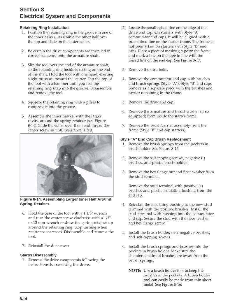
8.14
Section 8Electrical System and Components
Retaining Ring Installation1. Position the retaining ring in the groove in one of
the inner halves. Assemble the other half overthe top and slide on the outer collar.
2. Be certain the drive components are installed incorrect sequence onto the armature shaft.
3. Slip the tool over the end of the armature shaft,so the retaining ring inside is resting on the endof the shaft. Hold the tool with one hand, exertingslight pressure toward the starter. Tap the top ofthe tool with a hammer until you feel theretaining ring snap into the groove. Disassembleand remove the tool.
4. Squeeze the retaining ring with a pliers tocompress it into the groove.
5. Assemble the inner halves, with the largercavity, around the spring retainer (see Figure8-14). Slide the collar over them and thread thecenter screw in until resistance is felt.
Figure 8-14. Assembling Larger Inner Half AroundSpring Retainer.
6. Hold the base of the tool with a 1 1/8" wrenchand turn the center screw clockwise with a 1/2"or 13 mm wrench to draw the spring retainer uparound the retaining ring. Stop turning whenresistance increases. Disassemble and remove thetool.
7. Reinstall the dust cover.
Starter Disassembly1. Remove the drive components following the
instructions for servicing the drive.
2. Locate the small raised line on the edge of thedrive end cap. On starters with Style "A"commutator end caps, it will be aligned with apremarked line on the starter frame. The frame isnot premarked on starters with Style "B" endcaps. Place a piece of masking tape on the frameand mark a line on the tape in line with theraised line on the end cap. See Figure 8-17.
3. Remove the thru bolts.
4. Remove the commutator end cap with brushesand brush springs (Style "A"). Style "B" end capsremove as a separate piece with the brushes andcarrier remaining in the frame.
5. Remove the drive end cap.
6. Remove the armature and thrust washer (if soequipped) from inside the starter frame.
7. Remove the brush/carrier assembly from theframe (Style "B" end cap starters).
Style "A" End Cap Brush Replacement1. Remove the brush springs from the pockets in
brush holder. See Figure 8-15.
2. Remove the self-tapping screws, negative (-)brushes, and plastic brush holder.
3. Remove the hex flange nut and fiber washer fromthe stud terminal.
Remove the stud terminal with positive (+)brushes and plastic insulating bushing from theend cap.
4. Reinstall the insulating bushing to the new studterminal with the positive brushes. Install thestud terminal with bushing into the commutatorend cap. Secure the stud with the fiber washerand hex flange screw.
5. Install the brush holder, new negative brushes,and self-tapping screws.
6. Install the brush springs and brushes into thepockets in brush holder. Make sure thechamfered sides of brushes are away from thebrush springs.
NOTE: Use a brush holder tool to keep thebrushes in the pockets. A brush holdertool can easily be made from thin sheetmetal. See Figure 8-16.

8.15
Section 8Electrical System and Components
8
Figure 8-15. Style "A" Commutator End Cap withBrushes.
Figure 8-17. Starter Assembly Match Marks.
For Style "A" Commutator End Caps:4. Install the brush holder tool to keep the brushes
in the pockets of the commutator end cap.
5. Align the match marks on the commutator endcap and starter frame. Hold the drive end andcommutator end caps firmly to the starter frame.Remove the brush holder tool.
For Style "B" Commutator End Caps:4. If the brush assembly is not being replaced,
position the brushes in their pockets in thecarrier, move them to the retracted position, andinstall carton staples to retain them. See Figure8-18.
5. Align the terminal stud block with the notch inthe starter frame and slide the brush/carrierassembly into the frame. The commutator willpush the carton staples out as the brushassembly is inserted. Position the end cap overthe brush assembly, so the holes for the thrubolts are aligned with those in the brush carrier.
Self-TappingScrew
Negative(-) Brush
Stud Terminal with Positive (+) Brushes
Negative (-) Brush
Self-TappingScrew
Brush Springs(Under Brushes)
1 3/4"
Sheet Metal BrushHolder Tool
Brush Holder Tool InstalledOver Brushes and End Cap
1/2"
1"
2 1/2"
Figure 8-16. Brush Holder Tool (Style "A" End Cap).
Style "B" End Cap Brush ReplacementStarters with Style "B" end caps have the brushes in aplastic carrier housing, separate from the end cap.Replacement brushes come preassembled in thecarrier housing, retained with two carton staples.
Commutator ServiceClean the commutator with a coarse, lint free cloth.Do not use emery cloth.
If the commutator is badly worn or grooved, turn itdown on a lathe or replace the armature.
Starter Reassembly1. Place the thrust washer (if so equipped) over the
drive shaft of the armature.
2. Insert the armature into the starter frame. Makesure the magnets are closer to the drive shaft endof armature. The magnets will hold the armatureinside the frame.
3. Install the drive end cap over the drive shaft.Make sure the match marks on the end cap andstarter frame are aligned. See Figure 8-17.
Figure 8-18. Style "B" Commutator End Cap withBrushes.
6. Install the thru bolts and tighten securely.
7. Lubricate the drive shaft with Kohler bendixstarter drive lubricant (see Section 2). Install thedrive components following the instructions forservicing the drive.
Match Marks

8.16
Section 8Electrical System and Components
Solenoid Shift Electric StartersThe following subsection covers the solenoid shift electric starters. Some of the information in the precedingsubsection relates also to this style of starter, so it is not repeated here. A Nippondenso or Delco-Remy solenoidshift starter may be used. The Nippondenso starter is covered first, and the Delco-Remy starter servicingfollows.
OperationWhen power is applied to the starter the electric solenoid moves the drive pinion out onto the drive shaft andinto mesh with the flywheel ring gear. When the pinion reaches the end of the drive shaft it rotates the flywheeland cranks the engine.
When the engine starts and the start switch is released the starter solenoid is deactivated, the drive lever movesback, and the drive pinion moves out of mesh with the ring gear into the retracted position.
Starter Disassembly1. Disconnect the wire from the solenoid.
2. Remove the hex nuts securing the solenoid, andremove the solenoid from the starter assembly.
3. Remove the two thru bolts.
4. Remove the commutator end cap.
StarterAssembly
Armature
Nut
DriveLever
DustCover
Solenoid
Nut
DrivePinion
DriveEnd Cap
Frame
Wire
Brushes
BrushHolder
Brush Spring
Insulator
CommutatorEnd Cap
ThruBolt
Front StopCollar
Retainer
Rear StopCollar
Figure 8-19. Nippondenso Solenoid Shift Starter.
5. Remove the insulator and brush springs fromthe brush spring holder.
6. Remove the armature from the frame.
7. Remove the drive lever and armature from thedrive end cap.

8.17
Section 8Electrical System and Components
8
NOTE: When removing the lever and armaturebe careful not to lose the thrust washer.
8. The stop collar consists of two similar pieces heldin place by being snapped over a retainer. Theretainer is held in place by a groove in thearmature shaft. To remove the stop collar thetwo pieces must be pried off the retainer.
9. When the stop collars are removed, the retainercan be removed from the armature shaft. ElectricStarter Service Kit (see Section 2) includes aspecial pliers for removing the retainer. Do notreuse the retainer.
Brush ReplacementThe brushes in the starter are part of the starterframe. Brush kit Part No. 52 221 01-S contains fourreplacement brushes and springs. If replacement isnecessary, all four brushes should be replaced.
1. Remove brushes from brush holder, and removebrush holder from frame.
2. Cut the brush lead wire at the edge of the postwith a pair of nippers.
3. File off burrs on the post.
4. The replacement brushes have a solid portion onthem which should be crimped on the post.
5. Solder the crimped portion to the post.
6. Replace the brush holder in the frame and placethe brushes in the brush holder. Reinstall thesprings. Snap the insulator into the brush holderto keep the springs from popping out.
Starter ServiceClean drive lever and armature shaft. Apply Kohlerelectric starter drive lubricant (See Section 2) to leverand shaft.
Starter Reassembly1. Install the drive pinion onto the armature shaft.
2. Slide the stop collar onto the armature shaftbelow the retaining ring groove. Make sure therecessed side of the stop collar is up.
3. Position a new retainer in the groove of thearmature shaft, and carefully tighten with apliers to secure.
NOTE: Always use a new retainer. Do not nickor damage armature shaft.
4. Use an open end wrench and slide the stop collarup, until the recessed section encases theretaining ring and locks the collar into position.See Figure 8-20.
Figure 8-20. Lock Collar around Retaining Ring.
5. Install the thrust washer onto the armature shaftand lightly lubricate the end of the shaft withdrive lubricant.
6. Position the lubricated drive lever around thedrive pinion assembly and insert the assemblyinto the drive end cap. Seat the pivot section ofdrive lever into the corresponding section withinthe housing. See Figure 8-21.
Figure 8-21. Installing Armature.
7. Mount the brush holder to rear of starter frame.Install the four brushes into the correspondingslots. Then carefully work (set) each of the fourbrush springs into position behind the brushes.Slide the rubber insulating grommet onto thesmall corresponding plastic tab on frame. SeeFigure 8-22.

8.18
Section 8Electrical System and Components
Figure 8-22. Mounting Brush Holder to Frame.
8. Position the insulator over the brushes andsprings. Hold it firmly in place so the springs donot come out. See Figure 8-23.
Figure 8-23. Holding Insulator in Place.
9. Stand the armature/drive end cap assembly onend so the commutator end is up. Place brush/armature installation tool over the end of thearmature shaft until it rests against thecommutator. See Figure 8-24.
10. Carefully slide the frame, with the brush plateassembly, down over the tool and onto armatureand drive end cap, aligning the cutout with leversection (on top). The rubber insulating grommetshould also be up. See Figure 8-25.
NOTE: Maintain pressure on the insulatorwhile installing so the springs do notcome out.
Figure 8-25. Installing Frame with Brush PlateAssembly.
11. Remove the tool and install the commutator endcap, aligning the cutout with the insulatinggrommet. See Figure 8-26.
Figure 8-26. Installing End Cap.
12. Install and tighten the two thru bolts.
13. Make sure the dust cover is in place on thesolenoid. Install solenoid, engaging the plungerend with the yoke of the drive lever. Check bypulling solenoid towards the rear. Mount thesolenoid to the starter using the two hex flangenuts. Tighten securely. See Figure 8-27.Figure 8-24. Tool on end of Armature.

8.19
Section 8Electrical System and Components
8
Figure 8-27. Installing Solenoid.
14. Connect the braided (brush) lead to lower mainsolenoid terminal and secure with the hex flangenut. See Figure 8-28.
Figure 8-28. Connecting Brush Lead.
Figure 8-29. Delco-Remy Starter.
Starter Disassembly1. Remove the hex nut and disconnect the positive
(+) brush lead/bracket from the solenoidterminal.
2. Remove the three screws securing the solenoid tothe starter. See Figure 8-30.
Figure 8-30. Removing Solenoid Screws.
3. If the solenoid was mounted with Phillips headscrews, separate the solenoid and plunger springfrom the drive end cap. If the solenoid wasmounted with external Torx head screws, theplunger is part of the solenoid, unhook theplunger pin from the drive lever. Remove thegasket from the recess in the housing. See Figures8-31 and 8-32.
NOTE: Test procedure for checking starter solenoidon pages 8.26 and 8.27.
Figure 8-31. Solenoid Removed From Starter.
Delco-Remy Starters
Some solenoidsare fastenedwith externalTorx headscrews.

8.20
Section 8Electrical System and Components
Figure 8-32. Removing Plunger.
4. Remove the two thru (larger) bolts. See Figure8-33.
Figure 8-33. Removing Thru Bolts.
5. Remove the commutator end plate assembly,containing the brush holder, brushes, springs,and locking caps. Remove the thrust washerfrom inside the commutator end. See Figure 8-34.
Figure 8-34. Removing Commutator End PlateAssembly.
6. Remove the frame from the armature and driveend cap. See Figure 8-35.
Figure 8-35. Starter Frame Removed.
7. Remove the drive lever pivot bushing andbacking plate from the end cap. See Figure 8-36.
Figure 8-36. Removing Pivot Bushing and BackingPlate.
8. Take out the drive lever and pull the armatureout from the drive end cap. See Figure 8-37.
9. Remove the thrust washer from the armatureshaft. See Figure 8-37.

8.21
Section 8Electrical System and Components
8
12. Remove the drive pinion assembly from thearmature.
13. Clean the parts as required.
NOTE: Do not soak the armature or use solventwhen cleaning. Wipe clean using a softcloth, or use compressed air.
Inspection
Drive PinionCheck and inspect the following areas:
a. The pinion teeth for abnormal wear ordamage.
b. The O.D. surface between the pinion and theclutch mechanism for nicks, or irregularitieswhich could cause seal damage.
c. Check the drive clutch by holding the clutchhousing and rotating the pinion. Pinionshould rotate in one direction only.
Brushes and SpringsInspect both the springs and brushes for wear,fatigue, or damage. Measure the length of each brush.The minimum length for each brush is 7.6 mm(0.300 in.). See Figure 8-40. Replace the brushes if theyare worn undersize, or their condition isquestionable.
Figure 8-40. Brush Checking.
Armature1. Clean and inspect the commutator (outer
surface). The mica insulation of the commutatormust be lower than the O.D. surface (undercut) toensure proper operation of the commutator. SeeFigure 8-41.
Figure 8-39. Removing Retaining Ring.
Figure 8-37. Armature and Lever Removed.
10. Push the stop collar down to expose the retainingring. See Figure 8-38.
Figure 8-38. Retaining Ring Details.
11. Remove the retainer from the armature shaft.Save the stop collar.
NOTE: Do not reuse the old retainer.
Wear limit length:7.6 mm (0.300 in.)

8.22
Section 8Electrical System and Components
Figure 8-41. Commutator Mica Inspection.
2. Use an ohmmeter set to the Rx1 scale. Touch theprobes between two different segments of thecommutator, and check for continuity. See Figure8-42. Test all the segments. Continuity must existbetween all or the armature is bad.
Continuity CheckArmatureCoil
InsulationCheck
Figure 8-42. Armature Checks.
3. Check for continuity between the armature coilsegments and the commutator segments. SeeFigure 8-42. There should be no continuity. Ifcontinuity exists between any two, the armatureis bad.
4. Check the armature windings/insulation forshorting.
Shift ForkCheck that the shift fork is complete, and the pivot andcontact areas are not excessively worn, cracked orbroken.
Brush ReplacementThe brushes and springs are serviced as a set (4). UseBrush and Spring Kit, Kohler Part No. 52 221 01-S, ifreplacement is necessary.
1. Perform steps 1-5 in Starter Disassembly.
Commutator O.D.
Mica Insulation
2. Remove the two screws securing the brushholder assembly to the end cap (plate). Note theorientation for reassembly later. See Figure 8-43.Discard the old brush holder assembly.
Figure 8-43. Removing Brush Holder.
3. Clean the component parts as required.
4. The new brushes and springs comepreassembled in a brush holder with aprotective sleeve that will also serve as aninstallation tool. See Figure 8-44.
Figure 8-44. Service Brush Kit.
5. Perform Steps 10-13 in the “Starter Reassembly”sequence. (Installation must be done after thearmature, drive lever and frame are installed, ifthe starter has been disassembled.)
Starter ServiceClean the drive lever and armature shaft. ApplyKohler electric starter drive lubricant (See Section 2)to the lever and shaft (Versilube G322L or Mobil TempSHC 32). Clean and check the other starter parts forwear or damage as required.

8.23
Section 8Electrical System and Components
8
4. Apply a small amount of oil to the bearing in thedrive end cap, and install the armature with thedrive pinion.
5. Lubricate the fork end and center pivot of thedrive lever with drive lubricant (See Section 2).Position the fork end into the space between thecaptured washer and the rear of the pinion.
6. Slide the armature into the drive end cap, and atthe same time seat the drive lever into thehousing.
NOTE: Correctly installed, the center pivot sectionof the drive lever will be flush or below themachined surface of the housing whichreceives the backup washer. See Figure 8-47.
Starter Reassembly1. Apply new drive lubricant (See Section 2) to the
armature shaft splines. Install the drive piniononto the armature shaft.
2. Install and assemble the stop collar/retainerassembly.
a. Install the stop collar down onto thearmature shaft with the counter bore (recess)up.
b. Install a new retainer in the larger (rear)groove of the armature shaft. Squeeze with apliers to compress it in the groove.
c. Slide the stop collar up and lock it into place,so the recess surrounds the retainer in thegroove. If necessary, rotate the pinion outwardon the armature splines against the retainerto help seat the collar around the retainer.
Figure 8-45. Installing Stop Collar/Retainer.
NOTE: Always use a new retainer. Do not reuseold retainers, which have been removed.
3. Install the offset thrust (stop) washer so thesmaller offset of washer faces the retainer/collar.See Figure 8-46.
Figure 8-46. Thrust Washer Installation.
Figure 8-47. Installing Armature and Pivot Lever.
7. Install the backup washer followed by therubber grommet, into the matching recess of thedrive end cap. The molded recesses in thegrommet should be out, matching and alignedwith those in the end cap. See Figure 8-48.
Figure 8-48. Installing Backup Washer andGrommet.

8.24
Section 8Electrical System and Components
8. Install the frame with the small notch forward,onto the armature and drive end cap. Align thenotch with the corresponding section in therubber grommet. Install the drain tube in rearcutout, if it was removed previously. See Figure8-49.
Figure 8-49. Installing Frame and Drain Tube.
9. Install the flat thrust washer onto the commutatorend of the armature shaft. See Figure 8-50.
Figure 8-50. Installing Thrust Washer.
10. Starter reassembly when replacing the Brushes/Brush Holder Assembly:
a. Hold the starter assembly vertically on theend housing, and carefully position theassembled brush holder assembly with thesupplied protective tube, against the end ofthe commutator/armature. The mountingscrew holes in the metal clips must be up/out. Slide the brush holder assembly downinto place around the commutator, and installthe positive (+) brush lead grommet in thecutout of the frame. See Figure 8-51. Save theprotective tube, it may be used for futureservicing.
Figure 8-51. Installing Brush Holder Assembly withSupplied Tube.
Starter reassembly when not replacing the Brushes/Brush Holder Assembly:
a. Carefully unhook the retaining caps from overeach of the brush assemblies. Do not lose thesprings.
Figure 8-52. Removing Retaining Caps.
b. Position each of the brushes back in their slots sothey are flush with the I.D. of the brush holderassembly. Insert Brush Installation Tool withextension, or use the tube described above from aprior brush installation, through the brushholder assembly, so the holes in the metalmounting clips are up/out.
c. Install the brush springs and snap on the fourretainer caps. See Figure 8-53.
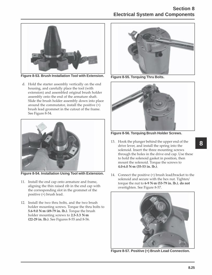
8.25
Section 8Electrical System and Components
8
Figure 8-53. Brush Installation Tool with Extension.
d. Hold the starter assembly vertically on the endhousing, and carefully place the tool (withextension) and assembled original brush holderassembly onto the end of the armature shaft.Slide the brush holder assembly down into placearound the commutator, install the positive (+)brush lead grommet in the cutout of the frame.See Figure 8-54.
Figure 8-54. Installation Using Tool with Extension.
11. Install the end cap onto armature and frame,aligning the thin raised rib in the end cap withthe corresponding slot in the grommet of thepositive (+) brush lead.
12. Install the two thru bolts, and the two brushholder mounting screws. Torque the thru bolts to5.6-9.0 N·m (49-79 in. lb.). Torque the brushholder mounting screws to 2.5-3.3 N·m(22-29 in. lb.). See Figures 8-55 and 8-56.
Figure 8-55. Torquing Thru Bolts.
Figure 8-56. Torquing Brush Holder Screws.
13. Hook the plunger behind the upper end of thedrive lever, and install the spring into thesolenoid. Insert the three mounting screwsthrough the holes in the drive end cap. Use theseto hold the solenoid gasket in position, thenmount the solenoid. Torque the screws to4.0-6.0 N·m (35-53 in. lb.).
14. Connect the positive (+) brush lead/bracket to thesolenoid and secure with the hex nut. Tighten/torque the nut to 6-9 N·m (53-79 in. lb.), do notovertighten. See Figure 8-57.
Figure 8-57. Positive (+) Brush Lead Connection.

8.26
Section 8Electrical System and Components
Solenoid Test Procedure
Solenoid Shift Style StartersDisconnect all leads from the solenoid including thepositive brush lead attached to the lower studterminal. Remove the mounting hardware andseparate the solenoid from the starter for testing.
Test 1 Solenoid Pull-In Coil/Plunger ActuationUse a 12 volt power supply and two test leads.Connect one lead to the flat spade S/start terminal onthe solenoid. Momentarily* connect the other lead tothe lower large post terminal. See Figure 8-58.When the connection is made the solenoid shouldenergize (audible click), and the plunger retract.Repeat the test several times. If the solenoid fails toactivate, it should be replaced.
*NOTE: DO NOT leave the 12 volt test leadsconnected to the solenoid for any time overwhat is necessary for performing each of theindividual tests. Internal damage to thesolenoid may otherwise occur.
Figure 8-58. Testing Pull-In Coil/Plunger Actuation.
Test 2 Solenoid Pull-In Coil/Contact Continuity TestUse an ohmmeter set to the audible or Rx2K scale, andconnect the two ohmmeter leads to the two large postterminals. Perform the preceding test (1) and check forcontinuity. See Figure 8-59. The ohmmeter shouldindicate continuity, if no continuity is indicated thesolenoid should be replaced. Repeat test several timesto confirm condition.
12 volt Test LeadsMomentaryConnection Only
Figure 8-59. Testing Pull-In Coil/Solenoid ContactContinuity.
Test 3 Solenoid Hold-In Coil Function TestConnect one 12 volt test lead to the flat spade S/startterminal on the solenoid, and the other lead to thebody or mounting surface of the solenoid. Then,manually push the plunger In and check if the Hold-In coil holds the plunger retracted. See Figure 8-60. Donot allow the test leads to remain connected to thesolenoid for a prolonged period of time. If the plungerfails to stay retracted, the solenoid should bereplaced.
12 volt Test LeadsMomentaryConnection Only
VOM Leads
Figure 8-60. Testing Hold-In Coil/Function Test.
Manually PushPlunger In
12 volt Test LeadsConnect Only LongEnough to Test

8.27
Section 8Electrical System and Components
8
Test 4 Solenoid Hold-In Coil/Contact Continuity TestUse an ohmmeter set to the audible or Rx2K scale, andconnect the two ohmmeter leads to the two large postterminals. Perform the preceding test (3) and check forcontinuity. See Figure 8-61. The meter should indicatecontinuity, if no continuity is indicated the solenoidshould be replaced. Repeat test several times toconfirm condition.
Figure 8-61. Testing Hold-In Coil/Solenoid ContactContinuity.
PlungerPushed In
VOM MeterLeads
12 volt Test Leads

9.1
Section 9Disassembly
9
Section 9Disassembly
GeneralThe following sequence is suggested for completeengine disassembly. This procedure can be varied toaccommodate options or special equipment.
Clean all parts thoroughly as the engine isdisassembled. Only clean parts can be accuratelyinspected and gauged for wear or damage. There aremany commercially available cleaners that willquickly remove grease, oil, and grime from engineparts. When such a cleaner is used, follow theManufacturer’s instructions and safety precautionscarefully.
Make sure all traces of the cleaner are removed beforethe engine is reassembled and placed into operation.Even small amounts of these cleaners can quicklybreak down the lubricating properties of engine oil.
Typical Disassembly Sequence1. Remove spark plug.2. Drain oil and remove oil filter.3. Remove muffler.4. Remove air cleaner.5. Remove throttle control bracket.6. Remove carburetor and governor lever.7. Remove fuel tank.8. Remove retractable starter.9. Remove fuel pump.
10. Remove electrical starter.11. Remove rectifier-regulator.12. Remove Oil Sentry.13. Remove valve cover.14. Remove cylinder head baffle.15. Remove blower housing and baffles.16. Remove carburetor adapter and heat deflector.17. Remove ignition module.18. Remove fuel line.
19. Remove cylinder head, push rods, and gasket.20. Remove drive cup, grass screen, flywheel, and
fan.21. Remove stator and wiring harness.22. Remove closure plate.23. Remove camshaft and hydraulic lifters.24. Remove balance shaft.25. Remove connecting rod and piston.26. Remove crankshaft.27. Remove flywheel end oil seal.28. Remove governor cross shaft and governor gear.
Disconnect Spark Plug LeadNOTE: Pull on boot only, to prevent damage to spark
plug lead.
Drain Oil From Crankcase and RemoveOil Filter
1. Remove the oil drain plug and oil fill cap/dipstick. See Figure 9-1.
2. Allow ample time for the oil to drain from thecrankcase and oil filter.
3. Remove and discard the oil filter.
Figure 9-1. Location of Oil Drain Plug and Filter.
Oil Drain PlugOil Filter
WARNING: Accidental Starts!Disabling engine. Accidental starting can cause severe injury or death. Before working on the engine or equipment,disable the engine as follows: 1) Disconnect the spark plug lead(s). 2) Disconnect negative (-) battery cable from battery.

9.2
Section 9Disassembly
Remove Air Cleaner1. Remove the knob and air cleaner cover. See
Figure 9-4.
Remove Muffler1. Remove the four hex flange screws securing the
muffler to the upper and lower mountingbrackets. See Figures 9-2 and 9-3.
2. Remove the muffler from the mounting bracketsand exhaust inlet pipe.
3. Remove the two hex flange nuts from the exhaustport studs and take off the exhaust inlet pipe andgasket.
Figure 9-2. Removing Muffler.
Figure 9-3. Removing Muffler.
Figure 9-4. Removing Air Cleaner Cover.
2. Remove the wing nut, washer, element cover,element and precleaner. See Figure 9-5.
Figure 9-5. Removing Air Cleaner Elements.
Muffler
Hex FlangeScrews
UpperMufflerBracket
Lower MountingBracket
Hex Flange Screws
Muffler
Knob
Air CleanerCover
AirCleanerBase
Wing Nut
ElementCover
PaperElement
FoamPrecleaner

9.3
Section 9Disassembly
9
3. Remove the hex flange nuts from the mountingstuds, and take off the air cleaner mountingbracket, spitback cup or collector plate, andgasket as equipped. See Figure 9-6.
Figure 9-7. Removing Air Cleaner Base.
Remove Throttle Control Bracket1. Remove the two mounting screws securing the
throttle control bracket and ground lead (somemodels) to the crankcase. See Figure 9-8.
2. Mark the governor spring hole location andunhook the spring from the lever of the throttlecontrol bracket. See Figure 9-8 and 9-9.
Figure 9-6. Removing Spitback Cup and AirCleaner Base.
4. Loosen the hose clamp and disconnect thebreather hose from the rocker arm cover. Removethe air cleaner base from the studs and disconnectthe choke linkage from the carburetor chokelever. See Figure 9-7.
Figure 9-8. Removing Throttle Control Bracket.
Figure 9-9. Removing Spring From Throttle Lever.
Air CleanerBase
Intake Studs
SpitbackCup
ChokeLinkage
AirCleanerBase
MountingScrews Ground
Lead
GovernorSpring
ThrottleBracket Lever

9.4
Section 9Disassembly
Remove Carburetor and Governor Lever
WARNING: Explosive Fuel!Gasoline may be present in the carburetor and fuel system.Gasoline is extremely flammable, and its vapors can explodeif ignited. Keep sparks, open flames, and other sources ofignition away from the engine.
1. Remove the fuel line from the carburetor inletfitting. See Figure 9-10.
Figure 9-10. Removing Fuel Line From Carburetor.
2. Loosen the fastener securing the governor leverto the cross shaft.
3. Remove the carburetor and governor lever, withthe linkage attached, from the engine. See Figure9-11.
Figure 9-11. Removing Carburetor and GovernorLever.
Remove Fuel Tank
WARNING: Explosive Fuel!Gasoline may be present in the carburetor and fuel system.Gasoline is extremely flammable, and its vapors can explodeif ignited. Keep sparks, open flames, and other sources ofignition away from the engine.
1. Turn fuel shut-off valve to OFF (horizontal)position. Disconnect fuel line from valve.
2. Remove hex flange nuts from lower bracket andhex flange screws from upper bracket of fueltank. See Figure 9-12.
Figure 9-12. Removing Fuel Tank.
3. Remove the fuel tank.
Remove Retractable Starter1. Remove the five hex flange screws and retractable
starter. See Figure 9-13.
Figure 9-13. Removing Retractable Starter.
Carburetor
Fuel Line
Carburetor
Governor Leverand Linkage
Upper BracketMounting Screws
Shut-Off ValveLower Bracket
Hex Flange Nuts
RetractableStarter
Hex Flange Screw (5)
Fuel Tank

9.5
Section 9Disassembly
9
Remove Fuel Pump
WARNING: Explosive Fuel!Gasoline may be present in the carburetor and fuel system.Gasoline is extremely flammable, and its vapors can explodeif ignited. Keep sparks, open flames, and other sources ofignition away from the engine.
1. Disconnect the fuel line from the outlet and inletfittings of the fuel pump. See Figure 9-14.
2. Remove the two hex flange screws, fuel pump,and gasket.
2. If starter is mounted on studs with a fuel tank/solenoid bracket. See Figure 9-15.
a. Remove the two hex flange screws throughthe closure plate. Note installation of spacerwasher behind bracket on lower screw. SeeFigure 9-15.
b. Remove the screws securing the starter(pinion) cover to the blower housing. SeeFigure 9-16.
Figure 9-14. Removing Fuel Pump.
Remove Electric Starter
Electric Starter (Bendix Drive or Solenoid Shift)1. Disconnect the lead connected to the stud
terminal on the starter, or both leads from thesolenoid on solenoid shift starters.
Figure 9-16. Removing Starter (pinion) Cover.
c. Slide the starter and spacers off the studs.Note position of ground lead (if used). SeeFigure 9-17.
Figure 9-15. Removing Bendix Drive Starter.
Figure 9-17. Removing Starter and Spacers.
Outlet Inlet
Fuel PumpHex FlangeScrews
Fuel Tank/SolenoidMounting Bracket
StarterTerminal/Lead
Hex FlangeMountingScrews
Spacer
Cover Hex Flange Screws
Spacers
Starter

9.6
Section 9Disassembly
Figure 9-18. Removing Mounting Studs.
If the starter is mounted with two hex flange screws,remove the screws and pull the starter out frombehind the pinion cover.
Figure 9-20. Removing Rectifier-Regulator.
Remove Oil SentryTM
1. Disconnect the lead from the Oil SentryTM switch.
2. Remove Oil SentryTM switch from the oil filteradapter or adapter section of closure plate. SeeFigure 9-21.
Figure 9-19. Starter Mounted With Bolts.
Remove Rectifier-Regulator1. Remove the connector(s) from the rectifier-
regulator. See Figure 9-20.
2. Remove the two hex flange screws securing therectifier-regulator and the attached ground lead(non-metal blower housing only).
d. If removal of the mounting studs is required,use the two hex flange nuts from themounting studs, tightened flange to flange, toremove. See Figure 9-18.
Figure 9-21. Removing Oil SentryTM Switch.
Studs
Hex Flange Nuts
StarterMounting Bolts
Wire Connectors
Rectifier-Regulator
MountingScrews
Oil SentryTM
Switch
Lead

9.7
Section 9Disassembly
9
Remove Valve Cover1. Remove the five hex flange valve cover screws.
Note the assembly orientation of any attachedbrackets (lift, fuel tank, muffler) and loose spacersif used. See Figure 9-22.
NOTE: The valve cover is sealed to the cylinderhead using RTV silicone sealant. Whenremoving valve cover, use care not todamage the gasket surfaces of cover andcylinder head. To break the RTV seal,hold a block of wood against one of theflat faces of the valve cover. Strike thewood firmly with a mallet. If the sealdoesn't break loose after 1 or 2 attempts,repeat the procedure on the other side.
Remove Blower Housing and Baffles1. Remove the hex flange screws from the blower
housing and baffles. Disconnect the wire harnessfrom the key switch, if equipped. Remove theblower housing, intake tube and baffles. SeeFigures 9-24, 9-25, and 9-26.
Figure 9-22. Removing Valve Cover.
Remove Cylinder Head Baffle1. Remove the hex flange screws securing the
cylinder head baffle to the cylinder head. SeeFigure 9-23. Remove the baffle.
Figure 9-24. Removing Intake Side Cylinder Baffle.
Figure 9-25. Removing Starter Side Cylinder Baffle.
Figure 9-23. Removing Cylinder Head Baffle.Figure 9-26. Disconnecting Indicator Light Leadsand Removing Blower Housing.
LiftBracket
Muffler Bracket
Fuel TankBracket
ValveCover
Hex FlangeScrews
CylinderHead Baffle
CylinderBaffle
Cylinder Baffle(Starter Side)
Indicator LightConnectors
BlowerHousing

9.8
Section 9Disassembly
Remove Carburetor Adapter and HeatDeflector
1. Remove the two socket head cap screw securingcarburetor adapter, gaskets and heat deflector tothe cylinder head. See Figure 9-27.
2. Remove the carburetor adapter, heat shield, andgaskets from the engine. See Figure 9-27.
Figure 9-27. Removing Carburetor Adapter andHeat Deflector.
Remove Ignition Module1. Disconnect the kill lead from the ignition module
terminal. See Figure 9-28.
2. Rotate flywheel magnet away from ignitionmodule.
3. Remove the two hex flange screws and ignitionmodule.
Figure 9-29. Removing Fuel Line.
Remove Cylinder Head1. Remove the hex flange screws, spacer (from the
screw by the exhaust port), cylinder head, pushrods, and cylinder head gasket. See Figures 9-30and 9-31. Mark the push rods for reassembly.Discard the screws. Do not reuse.
Figure 9-28. Removing Ignition Module.
Remove Fuel Line1. Remove the hex flange screw, clip, and fuel line.
See Figure 9-29.
Figure 9-31. Removing Cylinder Head Gasket.
Figure 9-30. Removing Cylinder Head.KillLead
KillTerminal
Ignition Module
CylinderHeadGasket
Hex FlangeScrews
Breather ReedRetainer andBreather Reed
Hex FlangeScrew andSpacer
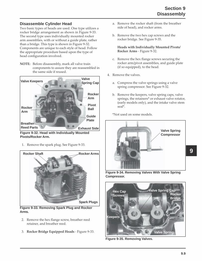
9.9
Section 9Disassembly
9
a. Remove the rocker shaft (from the breatherside of head), and rocker arms.
b. Remove the two hex cap screws and therocker bridge. See Figure 9-35.
Heads with Individually Mounted Pivots/Rocker Arms - Figure 9-32.
c. Remove the hex flange screws securing therocker arm/pivot assemblies, and guide plate(if so equipped), to the head.
4. Remove the valves.
a. Compress the valve springs using a valvespring compressor. See Figure 9-32.
b. Remove the keepers, valve spring caps, valvesprings, the retainers* or exhaust valve rotator,(early models only), and the intake valve stemseal*.
*Not used on some models.
Figure 9-34. Removing Valves With Valve SpringCompressor.
Disassemble Cylinder HeadTwo basic types of heads are used. One type utilizes arocker bridge arrangement as shown in Figure 9-33.The second type uses individually mounted rockerarm assemblies, with or without a guide plate, ratherthan a bridge. This type is shown in Figure 9-32.Components are unique to each style of head. Followthe appropriate procedure based upon the type ofhead configuration involved.
NOTE: Before disassembly, mark all valve traincomponents to assure they are reassembled inthe same side if reused.
Figure 9-32. Head with Individually MountedPivots/Rocker Arm.
1. Remove the spark plug. See Figure 9-33.
Figure 9-33. Removing Spark Plug and RockerArms.
2. Remove the hex flange screw, breather reedretainer, and breather reed.
3. Rocker Bridge Equipped Heads - Figure 9-33.
Figure 9-35. Removing Valves.
Rocker Shaft Rocker Arms
Spark Plugs
Valve SpringCompressor
Hex CapScrews
Valve Spring
ValveSpring Cap
Exhaust Side
RockerArm
PivotBall
Valve Keepers
RockerArm
BreatherReed Parts
GuidePlate
Keepers
Valve Spring CapRockerBridge
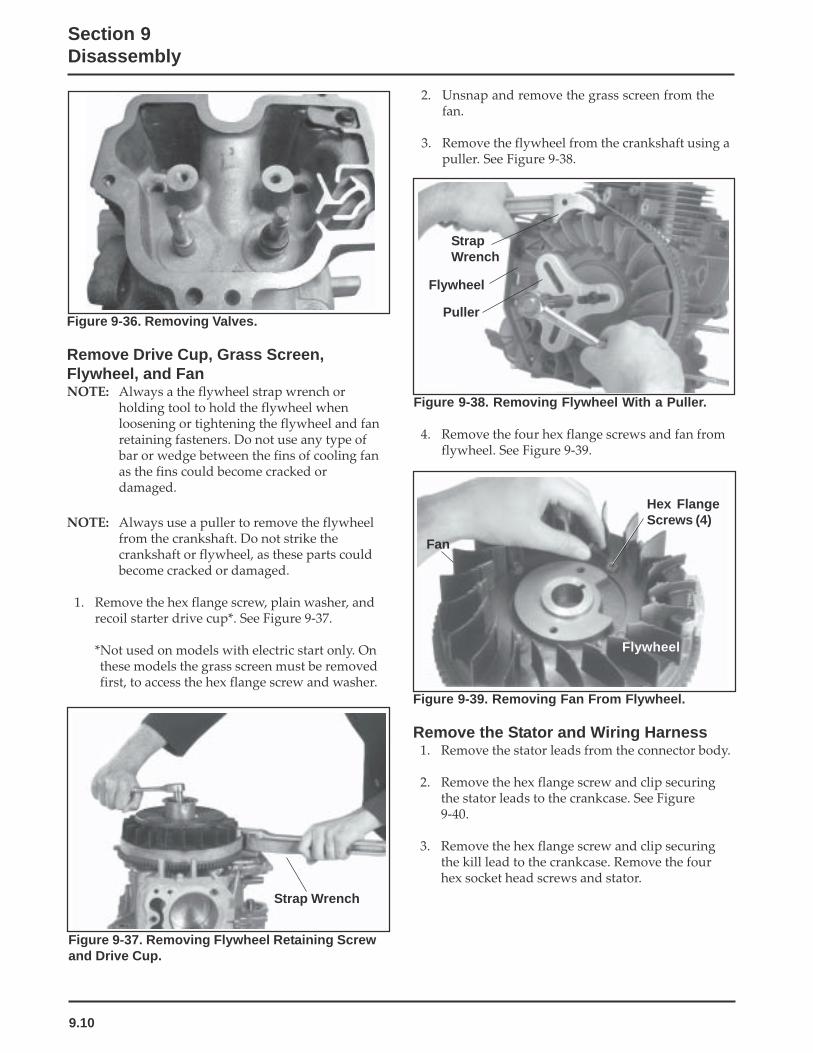
9.10
Section 9Disassembly
Figure 9-36. Removing Valves.
Remove Drive Cup, Grass Screen,Flywheel, and FanNOTE: Always a the flywheel strap wrench or
holding tool to hold the flywheel whenloosening or tightening the flywheel and fanretaining fasteners. Do not use any type ofbar or wedge between the fins of cooling fanas the fins could become cracked ordamaged.
NOTE: Always use a puller to remove the flywheelfrom the crankshaft. Do not strike thecrankshaft or flywheel, as these parts couldbecome cracked or damaged.
1. Remove the hex flange screw, plain washer, andrecoil starter drive cup*. See Figure 9-37.
*Not used on models with electric start only. Onthese models the grass screen must be removedfirst, to access the hex flange screw and washer.
2. Unsnap and remove the grass screen from thefan.
3. Remove the flywheel from the crankshaft using apuller. See Figure 9-38.
Figure 9-37. Removing Flywheel Retaining Screwand Drive Cup.
Figure 9-38. Removing Flywheel With a Puller.
4. Remove the four hex flange screws and fan fromflywheel. See Figure 9-39.
Figure 9-39. Removing Fan From Flywheel.
Remove the Stator and Wiring Harness1. Remove the stator leads from the connector body.
2. Remove the hex flange screw and clip securingthe stator leads to the crankcase. See Figure9-40.
3. Remove the hex flange screw and clip securingthe kill lead to the crankcase. Remove the fourhex socket head screws and stator.
Fan
Hex FlangeScrews (4)
Strap Wrench
StrapWrench
Flywheel
Puller
Flywheel

9.11
Section 9Disassembly
9
Figure 9-40. Removing Stator.
Remove Closure Plate1. Remove the twelve hex flange screws securing the
closure plate to the crankcase. See Figure 9-41.
Figure 9-41. Removing Closure Plate.
2. Locate the splitting notches in the seam of theclosure plate and crankcase. See Figure 9-42. Prythe closure plate from the crankcase using a largeflat-blade screwdriver.
NOTE: Insert the screwdriver only in the splittingnotches. Do not pry on the gasket surfaces ofthe closure plate or crankcase as this cancause leaks.
Remove Oil Pickup, Oil Pressure ReliefValve, Oil Pump, and Oil Seal
1. Remove the oil seal from the closure plate. SeeFigure 9-43.
2. Remove the hex flange screw, clip, oil pickup, andO-Ring seal.
3. Identify the type of oil pressure relief valve used.If the relief valve assembly is like that shown inFigure 9-44, remove the hex socket screw,retaining bracket, valve body, piston, and spring.If the relief valve is like that shown in Figure 9-45removal is not necessary. See the note on the nextpage.
Figure 9-42. Splitting Notch of Closure Plate/Crankcase.
Figure 9-43. Removing Oil Seal and Pickup.
Figure 9-44. Removing Oil Pressure Relief ValveBody, Piston, and Spring (Early Style).
Relief ValveBracket
Hex SocketScrew
Spring
Piston
Valve Body
SplittingNotch
Oil Pickup

9.12
Section 9Disassembly
Figure 9-45. Later Style Oil Pressure Relief Valve.
*NOTE: Later style one-piece relief valves (Figure9-45) are staked in place and do not requireremoval unless replacement is intended.
4. Remove the three hex flange screws, oil pumpcover, O-Ring, and oil pump rotors. See Figure9-46.
Remove Camshaft and Hydraulic Lifters1. Remove the camshaft and shim. See Figure 9-47.
Figure 9-47. Removing Camshaft.
2. Mark or identify the hydraulic lifters as eitherintake or exhaust. See Figure 9-48. Remove thelifters from the crankcase.
NOTE: The intake hydraulic lifter is farthest fromthe crankcase gasket surface. The exhausthydraulic lifter is nearest to the crankcasegasket surface.
Figure 9-46. Removing Oil Pump.
Oil PumpCover
Hex Flange Screws
Oil PumpRotors
O-Ring
Figure 9-48. Identifying Hydraulic Lifters.
NOTE: Do not use a magnet to remove hydrauliclifters.
NOTE: Some applications do not requirecylinder head removal for lifterreplacement.
Exhaust ValveLifter
Intake ValveLifter
Shim
Camshaft
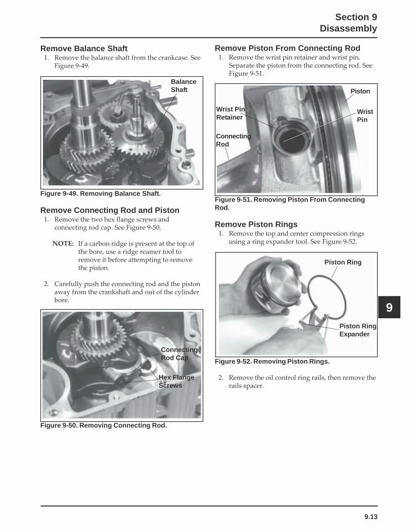
9.13
Section 9Disassembly
9
Remove Balance Shaft1. Remove the balance shaft from the crankcase. See
Figure 9-49.
Figure 9-49. Removing Balance Shaft.
Remove Connecting Rod and Piston1. Remove the two hex flange screws and
connecting rod cap. See Figure 9-50.
NOTE: If a carbon ridge is present at the top ofthe bore, use a ridge reamer tool toremove it before attempting to removethe piston.
2. Carefully push the connecting rod and the pistonaway from the crankshaft and out of the cylinderbore.
Figure 9-50. Removing Connecting Rod.
Remove Piston From Connecting Rod1. Remove the wrist pin retainer and wrist pin.
Separate the piston from the connecting rod. SeeFigure 9-51.
Figure 9-51. Removing Piston From ConnectingRod.
Remove Piston Rings1. Remove the top and center compression rings
using a ring expander tool. See Figure 9-52.
Figure 9-52. Removing Piston Rings.
2. Remove the oil control ring rails, then remove therails spacer.
ConnectingRod Cap
Hex FlangeScrews
Piston Ring
Piston RingExpander
BalanceShaft
Wrist PinRetainer
ConnectingRod
WristPin
Piston

9.14
Section 9Disassembly
Remove Crankshaft1. Remove the woodruff key from the flywheel end
of crankshaft.
2. Remove the crankshaft from the crankcase. SeeFigure 9-53.
Figure 9-53. Removing Crankshaft.
Remove Flywheel End Oil Seal1. Remove the oil seal from crankcase.
Remove Governor Cross Shaft andGovernor Gear
1. Remove the hitch pin and plain washer from thegovernor cross shaft. See Figure 9-54.
2. Remove the cross shaft and plain washer from thecrankcase.
Figure 9-54. Removing Governor Cross Shaft.
3. Remove the governor cross shaft oil seal from thecrankcase. See Figure 9-55.
Figure 9-55. Removing Cross Shaft Oil Seal.
4. If necessary, remove the governor gear andregulating pin. See Figure 9-56.
Cross Shaft Oil Seal
Figure 9-56. Removing Governor Gear.
NOTE: The governor gear is held onto the governorgear shaft by small molded tabs in the gear.When the gear is removed from the shaftthese tabs are destroyed. This will requirereplacement of the gear, therefore, removethe gear only if absolutely necessary (such aswhen reboring, doing major enginerebuilding, etc.).
Crankshaft
Regulating Pin
Governor Gear
Plain Washer
Hitch Pin
PlainWasher
GovernorCross Shaft

10.1
Section 10Internal Components
10
Section 10Inspection and Reconditioning
This section covers the operation, inspection, andrepair/reconditioning of major internal enginecomponents. The following components are notcovered in this section. They are covered in sections oftheir own:
Air Cleaner, Section 4Carburetor & External Governor, Section 5Ignition, Charging & Electric Starter, Section 8
Clean all parts thoroughly. Only clean parts can beaccurately inspected and gauged for wear or damage.There are many commercially available cleaners thatwill quickly remove grease, oil, and grime fromengine parts. When such a cleaner is used, follow themanufacturer’s instructions and safety precautionscarefully. Make sure all traces of the cleaner areremoved before the engine is reassembled and placedinto operation. Even small amounts of these cleanerscan quickly break down the lubricating properties ofengine oil.
Use an aerosol gasket remover, paint stripper, orlacquer thinner to remove any old sealant. Apply thesolvent, allow time for it to work, and then brush thesurface with a brass wire brush. After the old sealantis removed, clean the surface with isopropyl alcohol,lacquer thinner, or aerosol electrical contact cleaner.Do not scrape the surfaces, as any scratches, nicks, orburrs can result in leaks. See Service Bulletin 252 forfurther information.
Refer to A Guide to Engine Rebuilding (TP-2150-A)for additional information. Measurement Guide(TP-2159-B) and Engine Inspection Data Record(TP-2435) are also available; use these to recordinspection results.
Automatic Compression Release (ACR)This engine is equipped with an AutomaticCompression Release (ACR) mechanism. ACR lowerscompression at cranking speeds to make startingeasier.
OperationThe ACR mechanism consists of a lever and controlpin assembly attached to the gear on the camshaft. Atcranking speeds (700 RPM or lower), the control pinprotrudes above the exhaust cam lobe. This pushes theexhaust valve off its seat during the first part of thecompression stroke. The reduced compression resultsin an effective compression ratio during cranking ofabout 2:1.
After starting, engine speed increases to over 700RPM. Centrifugal force moves the lever and thecontrol pin drops into the recess in the exhaust camlobe. When in the recess, the control pin has no effecton the exhaust valve and the engine operates at fullpower.
When the engine is stopped, the spring returns thelever and control pin assembly to the compressionrelease position ready for the next start.
Camshaft
Inspection and ServiceInspect the gear teeth of the camshaft. If the teeth arebadly worn, chipped, or some are missing,replacement of the camshaft and crankshaft will benecessary.
Crankshaft
Inspection and ServiceInspect the gear teeth of the crankshaft. If the teeth arebadly worn, chipped, or some are missing,replacement of the crankshaft will be necessary.
Inspect the crankshaft bearings for scoring, grooving,etc. Do not replace bearings unless they shown signsof damage or are out of running clearancespecifications. If the crankshaft turns easily andnoiselessly, and there is no evidence of scoring,grooving, etc., on the races or bearing surfaces, thebearings can be reused.

10.2
Section 10Internal Components
Inspect the crankshaft keyways. If worn or chipped,replacement of the crankshaft will be necessary.Inspect the crankpin for score marks or metallicpickup. Slight score marks can be cleaned with crocuscloth soaked in oil. If wear limits, as stated in“Specifications and Tolerances” are exceeded, it willbe necessary to either replace the crankshaft or regrindthe crankpin to 0.25 mm (0.010 in.) undersize. Ifreground, a 0.25 mm (0.010 in.) undersize connectingrod (big end) must then be used to achieve properrunning clearance. Measure the crankpin for size,taper, and out-of-round.
Crankcase
Inspection and ServiceCheck all gasket surfaces to make sure they are free ofgasket fragments. Gasket surfaces must also be free ofdeep scratches or nicks.
Check the cylinder bore wall for scoring. In severecases, unburned fuel can cause scuffing and scoring ofthe cylinder wall, washing the necessary lubricatingoils off the piston and cylinder wall. As raw fuel seepsdown the cylinder wall, the piston rings make metal tometal contact with the wall. Scoring of the cylinderwall can also be caused by localized hot spotsresulting from blocking cooling fins or frominadequate or contaminated lubrication.
If the cylinder bore is badly scored, excessively worn,tapered, or out of round, resizing is necessary. Use aninside micrometer to determine amount of wear (referto the “Specifications, Tolerances, and Special TorqueValues”, in Section 1), then select the nearest suitableoversize of either 0.25 mm (0.010 in.) or 0.50 mm(0.020 in.). Resizing to one of these oversizes willallow usage of the available oversize piston and ringassemblies. Initially, resize using a boring bar, then usethe following procedures for honing the cylinder.
HoningWhile most commercially available cylinder hones canbe used with either portable drills or drill presses, theuse of a low speed drill press is preferred as itfacilitates more accurate alignment of the bore inrelation to the crankshaft crossbore. Honing is bestaccomplished at a drill speed of about 250 RPM and60 strokes per minute. After installing coarse stones inhone, proceed as follows:
1. Lower hone into bore and after centering, adjustso that the stones are in contact with the cylinderwall. Use of a commercial cutting-cooling agent isrecommended.
2. With the lower edge of each stone positionedeven with the lowest edge of the bore, start drilland honing process. Move the hone up and downwhile resizing to prevent the formation of cuttingridges. Check the size frequently.
NOTE: Measure the piston diameter and resizethe bore to the piston to obtain thespecified running clearances. Keep inmind the temperatures caused by honingmay cause inaccurate measurements.Make sure the bore is cool whenmeasuring.
3. When the bore is within 0.064 mm (0.0025 in.) ofdesired size, remove the coarse stones andreplace with burnishing stones. Continue withthe burnishing stones until within 0.013 mm(0.0005 in.) of desired size and then use finishstones (220-280 grit) and polish to final size. Acrosshatch should be observed if honing is donecorrectly. The crosshatch should intersect atapproximately 23-33° off the horizontal. Too flatof an angle could cause the rings to skip and wearexcessively, too steep of an angle will result inhigh oil consumption (refer to Figure 10-1).
Figure 10-1. Cylinder Bore Crosshatch afterHoning.
4. After resizing, check the bore for roundness,taper, and size. Use an inside micrometer,telescoping gauge, or bore gauge to takemeasurements. The measurements should betaken at three locations in the cylinder - at the top,middle, and bottom. Two measurements shouldbe taken perpendicular to each other) at each ofthe three locations.
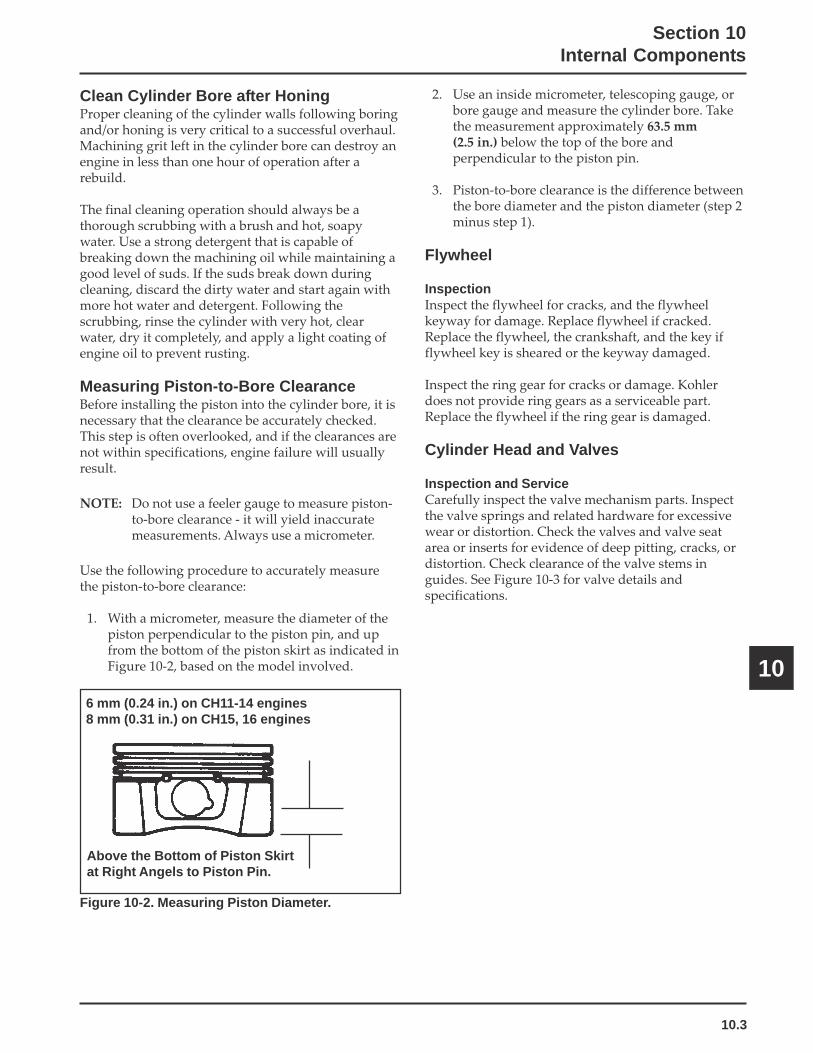
10.3
Section 10Internal Components
10
Clean Cylinder Bore after HoningProper cleaning of the cylinder walls following boringand/or honing is very critical to a successful overhaul.Machining grit left in the cylinder bore can destroy anengine in less than one hour of operation after arebuild.
The final cleaning operation should always be athorough scrubbing with a brush and hot, soapywater. Use a strong detergent that is capable ofbreaking down the machining oil while maintaining agood level of suds. If the suds break down duringcleaning, discard the dirty water and start again withmore hot water and detergent. Following thescrubbing, rinse the cylinder with very hot, clearwater, dry it completely, and apply a light coating ofengine oil to prevent rusting.
Measuring Piston-to-Bore ClearanceBefore installing the piston into the cylinder bore, it isnecessary that the clearance be accurately checked.This step is often overlooked, and if the clearances arenot within specifications, engine failure will usuallyresult.
NOTE: Do not use a feeler gauge to measure piston-to-bore clearance - it will yield inaccuratemeasurements. Always use a micrometer.
Use the following procedure to accurately measurethe piston-to-bore clearance:
1. With a micrometer, measure the diameter of thepiston perpendicular to the piston pin, and upfrom the bottom of the piston skirt as indicated inFigure 10-2, based on the model involved.
2. Use an inside micrometer, telescoping gauge, orbore gauge and measure the cylinder bore. Takethe measurement approximately 63.5 mm(2.5 in.) below the top of the bore andperpendicular to the piston pin.
3. Piston-to-bore clearance is the difference betweenthe bore diameter and the piston diameter (step 2minus step 1).
Flywheel
InspectionInspect the flywheel for cracks, and the flywheelkeyway for damage. Replace flywheel if cracked.Replace the flywheel, the crankshaft, and the key ifflywheel key is sheared or the keyway damaged.
Inspect the ring gear for cracks or damage. Kohlerdoes not provide ring gears as a serviceable part.Replace the flywheel if the ring gear is damaged.
Cylinder Head and Valves
Inspection and ServiceCarefully inspect the valve mechanism parts. Inspectthe valve springs and related hardware for excessivewear or distortion. Check the valves and valve seatarea or inserts for evidence of deep pitting, cracks, ordistortion. Check clearance of the valve stems inguides. See Figure 10-3 for valve details andspecifications.
Figure 10-2. Measuring Piston Diameter.
6 mm (0.24 in.) on CH11-14 engines8 mm (0.31 in.) on CH15, 16 engines
Above the Bottom of Piston Skirtat Right Angels to Piston Pin.

10.4
Section 10Internal Components
Hard starting, or loss of power accompanied by highfuel consumption may be symptoms of faulty valves.Although these symptoms could also be attributed toworn rings, remove and check the valves first. Afterremoval, clean the valve heads, faces, and stems with apower wire brush.
Then, carefully inspect each valve for defects such aswarped head, excessive corrosion, or worn stem end.Replace valves found to be in bad condition.
Valve GuidesIf a valve guide is worn beyond specifications, it willnot guide the valve in a straight line. This may resultin burnt valve faces or seats, loss of compression, andexcessive oil consumption.
Dimension Intake Exhaust
ABCDEFGH
Seat Angle
Insert O.D.
Guide Depth
Guide I.D.
Valve Head Diameter
Valve Face Angle
Valve Margin (Min.)
Valve Stem Diameter
89°
37.987/38.013 mm
6.5 mm
7.033/7.058 mm
35.63/35.37 mm
45°
1.5 mm
6.982/7.000 mm
89°
34.013/33.987 mm
6.5 mm
7.033/7.058 mm
31.63/31.37 mm
45°
1.5 mm
6.970/6.988 mm
To check valve guide to valve stem clearance,thoroughly clean the valve guide and, using a split-ball gauge, measure the inside diameter. Then, usingan outside micrometer, measure the diameter of thevalve stem at several points on the stem where itmoves in the valve guide. Use the largest stemdiameter to calculate the clearance. If the clearanceexceeds 7.134 mm (0.2809 in.) on intake or 7.159 mm(0.2819 in.) on exhaust valve, determine whether thevalve stem or the guide is responsible for the excessiveclearance.
If the valve stem diameter is within specifications,then recondition the valve guide.
Reconditioning Valve GuideThe valve guides in the cylinder head are notremovable. Use a 0.25 mm (0.010 in.) O/S reamer (SeeSection 2).
Intake Valve
C
D
D
H
G
Exhaust Valve
E F
ExhaustInsert
IntakeInsert
G
H
A
AB
B A F E
Figure 10-3. Valve Details.

10.5
Section 10Internal Components
10
Figure 10-4. Standard Valve Seat Cutter.
Lapping ValvesReground or new valves must be lapped in, to providefit. Lightly coat valve face with fine grade of grindingcompound. Use a hand valve grinder with suctioncup for final lapping. Clean and dry cylinder headand apply a light coating of SAE 10 oil to preventrusting.
Intake Valve Stem SealThese engines use valve stem seals on the intakevalves. Always use a new seal when valves areremoved from cylinder head. The seals should also bereplaced if deteriorated or damaged. Never reuse anold seal.
Pistons and Rings
InspectionScuffing and scoring of pistons and cylinder wallsoccurs when internal temperatures approach thewelding point of the piston, usually attributed toimproper lubrication, and/or overheating of theengine.
Normally, very little wear takes place in the pistonboss-piston pin area. If the original piston andconnecting rod can be reused after new rings areinstalled, the original pin can also be reused but newpiston pin retainers are required. The piston pin isincluded as part of the piston assembly - if the pinboss or the pin are worn or damaged, a new pistonassembly is required.
Ring failure is usually indicated by excessive oilconsumption and blue exhaust smoke. When ringsfail, oil is allowed to enter the combustion chamberwhere it is burned along with the fuel. High oilconsumption can also occur when the piston ring endgap is incorrect. Oil control is also lost when ring gapsare not staggered during installation.
When cylinder temperatures get too high, lacquer andvarnish collect on pistons causing rings to stick whichresults in rapid wear. A worn ring usually takes on ashiny or bright appearance.
Scratches on rings and pistons are caused by abrasivematerial such as carbon, dirt, or pieces of hard metal.
Detonation damage occurs when a portion of the fuelcharge ignites spontaneously from heat and pressureshortly after ignition. This creates two flame frontswhich meet and explode to create extreme hammeringpressures on a specific area of the piston. Detonationgenerally occurs from using fuels with low octane.
Preignition or ignition of the fuel charge before thetimed spark can cause damage similar to detonation.Preignition damage is often more severe thandetonation damage - often a hole is quickly burnedright through the piston dome. Preignition is causedby a hot spot in the combustion chamber from sourcessuch as: glowing carbon deposits, blocked fins,improperly seated valve, or wrong spark plug.
See Figure 10-5 for some common types of piston andring damage.
Valve Seat Cutter
Pilot
Valve Seat InsertsIntake valve seats are usually machined into thecylinder head, however, certain applications mayspecify hard alloy inserts. The valve seats are notreplaceable. If cracked or badly warped, the cylinderhead should be replaced.
Use a standard valve seat cutter (see Figure 10-4) andcut seat to dimensions shown in Figure 10-3 (valvedetails illustration).

10.6
Section 10Internal Components
Stuck, Broken Rings Abrasive Scratched Rings
Overheated or Deteriorated Oil Scored Piston and Rings
Figure 10-5. Common Types of Piston and Ring Damage.
Replacement pistons are available in STD bore size,and in 0.25 mm (0.010 in.), and 0.50 mm (0.20 in.)oversizes. Replacement pistons include new pistonring sets and new piston pins.
Service replacement piston rings sets are also availableseparately for STD, 0.25 mm (0.010 in.), and 0.50 mm(0.020 in.), oversized pistons. Always use new pistonrings when installing pistons. Never reuse old rings.
The cylinder bore must be deglazed before servicering sets are used.
Some important points to remember when servicingpiston rings:
1. If the cylinder bore does not need reboring and ifthe old piston is within wear limits and free ofscore or scuff marks, the old piston may bereused.
2. Remove old rings and clean up grooves. Neverreuse old rings.
3. Before installing the rings on the piston, place thetop two rings, each in turn, in its running area inthe cylinder bore and check end gap using afeeler gauge (see Figure 10-6). Compare findingsagainst specs below:
Top and Center Compression Ring End GapCH11, 12.5, 13, and 14
New Bore .............. 0.3/.05 mm (0.012/0.020 in)
Used Bore (Max.) . 0.77 mm (0.030 in)
CH15, 16Top Compression Ring End Gap
New Bore .............. 0.2800/0.5100 mm (0.011/0.020 in)
Used Bore (Max.) . 0.79 mm (0.031 in)
Center Compression Ring End GapNew Bore .............. 0.2200/0.4800 mm (0.0086/0.018 in)Used Bore (Max.) . 0.76 mm (0.029 in)

10.7
Section 10Internal Components
10
Figure 10-6. Measuring Piston Ring End Gap.
4. After installing the new compression (top andmiddle) rings on the piston, check the "piston-to-ring" side clearance. See Figure 10-7 Comparefindings against the maximum recommendedside clearances listed below. If side clearance aregreater than specified, a new piston must be used.
Compression Ring-To-Grove Side ClearanceCH11, 12.5, 13, and 14
Top ................. 0.040/0.150 mm (0.0016/0.0041 in.)Middle .......... 0.040/0.072 mm (0.0016/0.0028 in.)
CH15, 16Top ................. 0.0600/0.1050 mm (0.00236/0.00413 in)Middle .......... 0.0400/0.0850 mm (0.00157/0.00335 in.)
Figure 10-7. Measuring Piston Ring SideClearance.
Install Piston RingsTo install piston rings, proceed as follows:
NOTE: Rings must be installed correctly. Ringinstallation instructions are usually includedwith new rings sets. Follow instructionscarefully. Use a piston ring expander to installrings. Install the bottom (oil control) ring firstand the top compression ring last. Refer toFigure 10-8.
Figure 10-8. Piston Ring Installation.
1. Oil Control Ring (Bottom Groove): Install theexpander and then the rails. Make sure the endsof expander are not overlapped.
2. Compression Ring (Center Groove): Install thecenter ring using a piston ring installation tool.Make sure the “pip” mark is up and the PINKdykem stripe is to the left of end gap.
3. Compression Ring (Top Groove): Install the topring using a piston ring installation tool. Makesure the “pip” mark is up and the BLUE dykemstripe is to the left of end gap.
Connecting RodsOffset Stepped-Cap Connecting Rods are used in allthese engines.
Inspection and ServiceCheck bearing area (big end) for excessive wear, scoremarks, running and side clearances (refer to Section 1,Specifications, Tolerances, and Special Torque Values).Replace rod and cap if scored or excessively worn.
Service replacement connecting rods are available inSTD crankpin size and 0.25 mm (0.010 in.) undersize.Always refer to the appropriate parts information toensure that correct replacements are used.
Piston Ring
Piston
Top Compression Ring
Center Compression
Rails
ExpanderOil Control Ring
End Gap Dykem
‘‘Pip’’ Mark

10.8
Section 10Internal Components
Relief ValveBracket
Hex SocketScrew
Spring
Piston
Valve Body
Oil Pump
Inspection and ServicePump can be checked/replaced without removingclosure plate.
Oil Pressure Relief ValveIf an original style (five-piece) oil pressure relief valveis used (see Figure 10-9), check that piston and bodyare free of nicks or burrs. Check the spring for anywear or distortion. The free length of the springshould be approximately 0.992 in. Replace the springif worn, out of specification, or damaged/distorted.
If the later style (one-piece) oil pressure relief valve(see Figure 10-10) is used (staked to the closure plate),check to see that the internal spring-loaded piston isfree. Remove the valve only if it needs to be replaced.
Figure 10-10. One-Piece Oil Pressure Relief Valve.
Governor Gear
InspectionInspect the governor gear teeth. Look for any evidenceof worn, chipped, or cracked teeth. If one or more ofthese problems is noted, replace the governor gear.
The governor gear must be replaced once it isremoved from the engine.
Figure 10-9. Five-Piece Oil Pressure Relief Valve.
Hydraulic Lifters
InspectionCheck the base surface of the hydraulic lifters forwear or damage. If the lifters need to be replaced,apply a liberal coating of Kohler lubricant (see Section2) to the base of each new lifter before it is installed.
Bleeding the LiftersTo prevent a possible bent push rod or broken rockerarm, it is important to bleed any excess oil out of thelifters before they are installed.
1. Cut a 50-75 mm (2-3 in.) piece from the end of anold push rod and chuck it in a drill press.
2. Lay a rag or shop towel on the table of the drillpress and place the lifter, open end up, on thetowel.
3. Lower the chucked push rod until it contacts theplunger in the lifter. Slowly pump the plungertwo or three times to force the oil out of the feedhole in the side of the lifter.
Stamped Steel Valve CoverIf the engine has stamped steel valve cover, the sealingsurface must be checked for flatness prior toreinstallation. Hold the valve cover down firmlyagainst a flat, level surface or piece of glass, and checkaround the entire perimeter that a 0.012 in. (0.30 mm)feeler gauge cannot be inserted anywhere. See Figure10-11. If the gauge goes in anywhere, the cover needsto be replaced.
Figure 10-11. Checking with Feeler Gauge.

11.1
Section 11Reassembly
11
Section 11Reassembly
The following sequence is suggested for completeengine reassembly. This procedure assumes that allcomponents are new or have been reconditioned, andall component subassembly work has been completed.This procedure may be varied to accommodateoptions or special equipment.
NOTE: Make sure the engine is assembled using allspecified torque values, tightening sequences,and clearances. Failure to observespecifications could cause severe engine wearor damage.
NOTE: Always use new gaskets.
Typical Reassembly Sequence1. Install governor gear and cross shaft.2. Install crankshaft.3. Install piston rings.4. Assemble piston to connecting rod.5. Install piston and connecting rod.6. Install balance shaft.7. Install hydraulic lifters and camshaft.8. Check camshaft end play.9. Install closure plate.
10. Install oil pump.11. Install oil seal (PTO and Flywheel End).12. Install stator and wiring harness.13. Install flywheel, fan, grass screen and drive cup.14. Install fuel line.15. Install ignition module.16. Assemble and install cylinder head.17. Install carburetor adapter and heat deflector.18. Install baffles and blower housing.19. Install valve cover and muffler bracket.20. Install fuel pump.21. Install electric starter.22. Install fuel tank.23. Install rectifier-regulator.24. Install carburetor and external governor
components.25. Install throttle bracket.26. Install air cleaner base, air intake system, adjust
governor lever.
27. Install retractable starter.28. Install muffler.29. Prepare engine for operation.30. Test engine.
Install Governor Gear and Cross ShaftNOTE: Reuse of an old (removed) governor gear is
not recommended.
1. Install the thrust washer to governor gear shaft.
2. Position the regulating pin to governor gear/flyweights as shown in Figure 11-1. Slide thegovernor gear/regulating pin over the governorgear shaft.
Figure 11-1. Installing Governor Gear.
RegulatingPin
GovernorGear
ThrustWasher

11.2
Section 11Reassembly
Figure 11-2. Cross Shaft Oil Seal.
4. Install one plain washer to the cross shaft andinsert the cross shaft (from inside crankcase)through the crankcase and oil seal. See Figure11-3.
5. Install one plain washer and hitch pin.
Figure 11-4. Installing Crankshaft.
Install Piston RingsNOTE: For detailed piston inspection procedures
and piston ring installation procedure, referto Section 10.
Assemble Piston to Connecting Rod1. Assemble the piston, connecting rod, piston pin,
and piston pin retainers. See Figure 11-5.
Figure 11-5. Installing Piston To Connecting Rod.
Install Piston and Connecting RodNOTE: Proper orientation of the piston/connecting
rod inside the engine is extremely important.Improper orientation can cause extensivewear or damage.
1. Stagger the piston rings in the grooves until theend gaps are 120° apart.
Figure 11-3. Installing Cross Shaft.
Install Crankshaft1. Lubricate the flywheel end bearing surfaces of the
crankshaft and crankcase with engine oil.
2. Insert the crankshaft through the flywheel endbearing. See Figure 11-4.
3. Using the an oil seal installer, install a newgovernor cross shaft oil seal into the crankcase.See Figure 11-2.
PlainWasher
HitchPin
GovernorCrossShaft
Plain Washer
Cross ShaftOil Seal
SealInstaller
Crankshaft
Wrist Pin
Wrist PinRetainer
ConnectingRod
Piston

11.3
Section 11Reassembly
11
Figure 11-6. Installing Piston and Connecting Rod.
3. Place the ring compressor on the top surface ofthe crankcase and make certain it is seated downaround the entire circumference. The FLY arrowon the piston should point toward the flywheelside of the crankcase. See Figure 11-7. Use a soft,rubber grip hammer handle and tap the piston/connecting rod into the bore. The first tap shouldbe rather firm, so the oil ring moves from thecompressor into the bore in one smooth, quickmotion. Otherwise the oil ring rails may springout and jam between the ring compressor andthe top of the bore.
Figure 11-7. Piston Installation Identifier.
4. Lubricate the crankshaft journal and connectingrod bearing surfaces with engine oil. Install therod cap to the connecting rod.
5. Three different types of connecting rod bolts havebeen used in production, and each has a differentspecific torque value. See Figures 11-8 and 11-9.
The 8 mm straight shank style rod bolts must betorqued in increments to 22.7 N·m (200 in. lb.).The 8 mm step-down shank style rod bolts mustbe torqued in increments to 14.7 N·m(130 in. lb.). The 6 mm straight shank style rodbolts must be torqued in increments to 11.3 N·m(100. in. lb.). Illustrated instructions are alsoprovide in the service rod package.
2. Lubricate the cylinder bore, piston, and ringswith engine oil. Compress the piston rings usinga piston ring compressor. See Figure 11-6. Pushthe piston through the compressor so the oilcontrol (bottom) ring is just above the lower edgeof the compressor.
Piston RingCompressor InstalledAround Piston
Arrow MustPoint TowardsFlywheel
Torque these to 22.7 N·m (200 in. lb.)8 mm Straight Shank
Torque these to 14.7 N·m (130 in. lb.)8 mm Step-Down Shank
Torque these to 11.3 N·m (100 in. lb.)6 mm Straight Shank
Figure 11-8. Connecting Rod Bolts.

11.4
Section 11Reassembly
Figure 11-11a. Applying Camshaft Lubricant toBottom of Lifters.
3. Note the mark or tag identifying the hydrauliclifters as either intake or exhaust. Install thehydraulic lifters into the crankcase. See Figure11-11b.
NOTE: Install lifters in the same position asbefore disassembly. The exhaust liftersare located on the output shaft (oil pan)side of the engine while the intake liftersare located on the fan side of the engine.
Figure 11-9. Installing Connecting Rod Fasteners.
6. Rotate the crankshaft until the piston is at topdead center (TDC) in the cylinder bore.
Install Balance Shaft1. Lubricate the balance shaft bearing surfaces of the
crankcase and balance shaft with engine oil.
2. Align the timing mark on the balance shaft gearand the larger gear on the crankshaft. Lower thebalance shaft into the bearing surface in thecrankcase.
3. Make sure the balance shaft gear, large crankshaftgear and the governor gear teeth mesh and thetiming marks are aligned. See Figure 11-10.
Install Hydraulic Lifters and Camshaft1. See Hydraulic Lifters in Section 10 for lifter
preparation (bleed down) procedures.
2. Apply camshaft lubricant (Kohler Part No.25 357 14-S) to the bottom surface of each lifter.See Figure 11-11a. Lubricate the hydraulic liftersand the lifter bores in the crankcase with engineoil.
ConnectingRod Cap
Crankshaft TimingMark (Large Crankgear)
Balance ShaftTiming Mark
Figure 11-10. Aligning Timing Marks on Crank Gearand Balance Shaft Gear.
Figure 11-11b. Installing Hydraulic Lifters.
ConnectingRod Bolts

11.5
Section 11Reassembly
11
Figure 11-12. Aligning Timing Marks on Crank Gearand Cam Gear.
Determine Camshaft End Play1. Install the shim spacer, removed during
disassembly, to the camshaft.
2. Install the camshaft end play checking tool (seeSection 2) to the crankcase and camshaft. Securethe tool to the crankcase with the hex flangescrews provided. See Figure 11-13.
4. If the camshaft end play is not within thespecified range, remove the end play checkingtool and add, remove or replace shims asnecessary.
Several color coded shims are available:
White: 0.69215/0.73025 mm (0.02725/0.02875 in)Blue: 0.74295/0.78105 mm (0.02925/0.03075 in)Red: 0.79375/0.83185 mm (0.03215/0.03275 in)Yellow: 0.84455/0.88265 mm (0.03325/0.03475 in)Green: 0.89535/0.99345 mm (0.03525/0.03675 in)Gray: 0.94615/0.98425 mm (0.03725/0.03875 in)Black: 0.99695/1.03505 mm (0.03925/0.04075 in)
5. Reinstall the end play checking tool and recheckend play.
6. Repeat steps 4 and 5 until the end play is withinthe specified range.
Install Oil Pressure Relief Valve
Five-Piece Oil Pressure Relief Valve1. Place the relief valve body in the cavity of the
closure plate.
2. Insert the piston and spring into the body. SeeFigure 11-14.
Crankshaft Timing Mark(Small Crankgear)
CamshaftTiming Mark
4. Align the timing marks the camshaft gearand the smaller gear on the crankshaft. Lower thecamshaft into the bearing surface in crankcase.
5. Make sure the camshaft gear and the smallergear on the crankshaft mesh and the timingmarks are aligned. See Figure 11-12.
Hex FlangeScrews
Camshaft EndPlay Checking Tool Flat Feeler
Gauge
ShimSpacer
Figure 11-13. Checking Camshaft End Play.
3. Using a flat feeler gauge, measure the camshaftend play between the shim spacer and the endplay checking tool. Camshaft end play should be0.076/0.127 mm (0.003/0.005 in).
Oil Pressure ReliefValve Bracket
Hex Socket Screw
Spring
Piston
Relief Valve
Figure 11-14. Installing Oil Pressure Relief ValveBody, Plunger, and Spring.
3. Install the bracket and hex flange screw. SeeFigures 11-14 and 11-18.
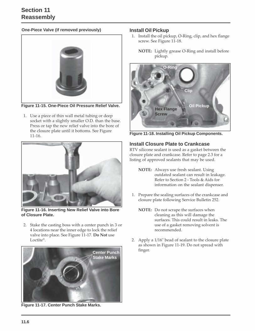
11.6
Section 11Reassembly
Install Oil Pickup1. Install the oil pickup, O-Ring, clip, and hex flange
screw. See Figure 11-18.
NOTE: Lightly grease O-Ring and install beforepickup.
One-Piece Valve (if removed previously)
Figure 11-15. One-Piece Oil Pressure Relief Valve.
1. Use a piece of thin wall metal tubing or deepsocket with a slightly smaller O.D. than the base.Press or tap the new relief valve into the bore ofthe closure plate until it bottoms. See Figure11-16.
Figure 11-16. Inserting New Relief Valve into Boreof Closure Plate.
2. Stake the casting boss with a center punch in 3 or4 locations near the inner edge to lock the reliefvalve into place. See Figure 11-17. Do Not useLoctite®.
Figure 11-17. Center Punch Stake Marks.
Center PunchStake Marks
O-Ring
Clip
Oil PickupHex FlangeScrew
Figure 11-18. Installing Oil Pickup Components.
Install Closure Plate to CrankcaseRTV silicone sealant is used as a gasket between theclosure plate and crankcase. Refer to page 2.3 for alisting of approved sealants that may be used.
NOTE: Always use fresh sealant. Usingoutdated sealant can result in leakage.Refer to Section 2 - Tools & Aids forinformation on the sealant dispenser.
1. Prepare the sealing surfaces of the crankcase andclosure plate following Service Bulletin 252.
NOTE: Do not scrape the surfaces whencleaning as this will damage thesurfaces. This could result in leaks. Theuse of a gasket removing solvent isrecommended.
2. Apply a 1/16" bead of sealant to the closure plateas shown in Figure 11-19. Do not spread withfinger.

11.7
Section 11Reassembly
11
Figure 11-19. Closure Plate Sealant Pattern.
3. Install the closure plate to the crankcase andinstall the twelve hex flange screws. Tighten thescrews hand tight.
4. Torque the fasteners, in the sequence shown inFigure 11-20 to 24.4 N·m (216 in. lb.).
Figure 11-22. Installing Oil Pump Cover.
Install Oil Pump1. Lubricate the oil pump cavity and oil pump
rotors with engine oil. Install the outer and inneroil pump rotors. See Figure 11-21.
Figure 11-20. Closure Plate Fastener TorqueSequence.
1
2 3
4
5
6
7
8
9
10
11
12
Inner Rotor
BalanceShaft
OuterRotor
Figure 11-21. Installing Oil Pump Gears and O-Ring.
2. Install the O-Ring in the groove in the closureplate.
3. Install the oil pump cover (machined side towardO-Ring). Secure with three hex flange screws. SeeFigure 11-22.
NOTE: Apply sealant to the oil pump cover hexflange screws to prevent leakage.
Torque the screws as follows:
First time installation on a new closure plate:6.2 N·m (55 in. lb.).
Reinstallation on a used closure plate:4.0 N·m (35 in. lb.).
Oil Pump Cover
Hex FlangeScrews

11.8
Section 11Reassembly
Figure 11-24. Installing Stator.
Install Fan and Flywheel
Warning: Damaging Crankshaft andFlywheel Can Cause Personal Injury!
Using improper procedures to install the flywheel can crack ordamage the crankshaft and/or flywheel. This not only causesextensive engine damage, but can also cause personal injury,since broken fragments could be thrown from the engine.Always observe and use the following precautions andprocedures when installing the flywheel.
NOTE: Before installing the flywheel make sure thecrankshaft taper and flywheel hub are clean,dry and completely free of lubricants. Thepresence of lubricants can cause the flywheelto be overstressed and damaged when theflange screw is torqued to specification.
NOTE: Make sure the flywheel key is installedproperly in the keyway. The flywheel canbecome cracked or damaged if the key is notinstalled properly in the keyway.
NOTE: Always use a flywheel strap or holding toolwrench to hold the flywheel when tighteningthe flywheel fastener. Do not use any type ofbar wedge between the cooling fins orflywheel ring gear, as these parts couldbecome cracked or damaged.
1. Install the fan, spacers and hex flange screws tothe flywheel. See Figure 11-25.
2. Torque the hex flange screws to 9.9 N·m (88 in.lb.).
Install Oil Seals (PTO End and FlywheelEnd)
1. Slide a seal protector sleeve, over the crankshaft.Generously lubricate the lips of the oil seal withlight grease. Slide the oil seal over the sleeve.
2. Use a seal driver, install the PTO end andflywheel end oil seals. See Figure 11-23.
Figure 11-23. Installing Oil Seals.
Install Stator and Wiring Harness1. Position the stator leads toward the hole in the
crankcase. Insert the stator leads through thehole to the outside of the crankcase. See Figure11-24.
2. Install the stator using four hex socket headscrews.
3. Torque the screws to 4.0 N·m (35 ft. lb.).
4. Secure the stator leads to the crankcase with theclip and hex flange screw.
5. Install the connector body to the stator leads.
6. Secure the kill lead to the crankcase with the clipand hex flange screw.
Driver
Oil Seal
Kill Lead
Stator Lead
Hex FlangeScrew & Clip
Stator

11.9
Section 11Reassembly
11
Figure 11-25. Installing Fan To Flywheel.
3. Install the woodruff key into the keyway in thecrankshaft.
4. Place the flywheel over the keyway/crankshaft.Install grass screen, drive cup, plain washer (flatside of plain washer towards the drive cup), andthe hex flange screw. See Figure 11-26.
5. Hold the flywheel with the strap wrench orholding tool and torque the hex flange screw to66.4 N·m (49 ft. lb.). See Figure 11-26.
Figure 11-27. Installing Fuel Line.
Install Ignition Module1. Rotate the flywheel so the magnet is away from
the ignition module bosses. Install the ignitionmodule to the bosses on the crankcase. Thedirectional arrow denoting proper flywheelrotation must be up. Move the module as farfrom the flywheel/magnet as possible. Tightenthe hex flange screws slightly.
2. Insert a 25 mm (0.010 in) flat feeler gauge or shimstock between the magnet and ignition module.See Figure 11-28.
Loosen the hex flange screws so the magnet pullsthe module against the feeler gauge.
Figure 11-26. Installing Flywheel.
Install Fuel Line1. Install the fuel line, clamp and hex flange screw.
See Figure 11-27.
Clip
Hex FlangeScrew
Fuel Line
Hex FlangeScrews
Magnet
Flat FeelerGauge
Ignition Module
Figure 11-28. Installing Ignition Module.
Fan
Flywheel
Hex FlangeScrews (4)
Flywheel
Plain Washer &Hex Flange Screw
Drive Cup
Grass Screen

11.10
Section 11Reassembly
Figure 11-30. Compressing Valve Springs.
Figure 11-29. Installing Rocker Bridge and Valves.
Figure 11-31. Installing Valve Keepers.
4. Rocker Bridge HeadsPosition the rocker arms over the valve stems androcker arm bridge. Insert the rocker shaft throughthe rocker bridge and rocker arms, from thebreather reed side. See Figure 11-32.
Valve SpringCompressor
KeepersValveSpringCap
Valve Springs
3. Tighten the hex flange screws as follows:
First Time Installation On A New Short Block:6.2 N·m (55 in. lb.).
All Reinstallations: 4.0 N·m (35 in. lb.).
4. Rotate the flywheel back and forth; check tomake sure the magnet does not strike the module.
5. Check the gap with a feeler gauge and readjust ifnecessary.
Final Air Gap: 0.203/0.305 mm (0.008/0.012 in).
6. Connect the kill lead to the tab terminal on theignition module.
Reassemble Cylinder Head Components(See Figure 11-29 thru 11-31)
1. Rocker Bridge Heads Only - Install the rockerbridge to the cylinder head. Make sure the small(counterbored) hole is toward the exhaust portside of the cylinder head. Secure the rockerbridge with two M6 hex cap screws. Torque thescrews to 9.9 N·m (88 in. lb.).
2. Install the intake valve stem seal, intake valve,spring seat, intake valve spring, and valve springcap. Compress the valve spring using a valvespring compressor and install the keepers.
3. Install the exhaust valve, valve spring, and valvespring cap. Compress the valve spring using avalve spring compressor and install the keepers.
NOTE: Exhaust valve rotators are no longerused. Do not attempt to install rotators ifa new head is being installed, or if headdid not use one originally.
Hex Cap Screws Rocker Bridge
Valves
Exhaust Valve Rotator(early models) Intake Valve
Spring Seat
Intake ValveStem Seal

11.11
Section 11Reassembly
11
Figure 11-33. Separate Pivot/Rocker Arm Styles.
5. Install the breather reed, reed retainer and securewith the M5 hex flange screw. Torque the screwto 6.2 N·m (55 in. lb) in new hole, or 3.9 N·m (35 in. lb.) in used hole. See Figure 11-34.
6. Install exhaust studs (if removed previously, ornew head is being installed). The threaded endwith the oval point or identification symbol mustbe out.
Install Cylinder Head1. Rotate the crankshaft to TDC of the compression
stoke and make sure the lifters are installed in thelifter bores with the socket up.
2. Reinstall the push rods in their original position.
Figure 11-32. Installing Rocker Arms.
Heads with Separate Pivots/Rocker ArmsPosition the pivots in the sockets of the rockerarms. Insert the screws through the pivots,rocker arms, and guide plate (some models only).Start the screws into the head and finger tightenonly at this time. See Figure 11-33.
RockerShaft
Rocker Arms
Spark Plug
Figure 11-34. Installing Cylinder Head.
3. Install a new cylinder head gasket and thecylinder head assembly on the crankcase. Slidethe spacer and washer onto one of the new headbolts, and install it in the #5 position (betweenthe intake and exhaust ports). See Figure 11-34. Ifthe engine has a high temperature cutout switch,insert the new long (90 mm) head bolt throughthe special washer (flat on one edge) and cutoutswitch, and install it in the #1 position. See Figure11-35. Install the remaining new head bolts.Following the sequence in Figure 11-35, torquethe bolts to 24 N·m (18 ft. lb.). Then repeat thesequence to a final torque of 48.9 N·m (36 ft. lb.).
NOTE: When installing cylinder heads, newhead bolts should always be used.
Figure 11-35. Cylinder Head Fastener TorqueSequence.
Hex FlangeScrews
Breather ReedRetainer andBreather Reed
HexFlangeScrewandSpacer
1
2
3
4
5

11.12
Section 11Reassembly
Figure 11-39. Connecting Oil Sentry™ IndicatorLight Leads.
2. Install the grommet around the high tension lead.Insert the grommet into the slot in the blowerhousing. Install the blower housing and bafflesusing hex flange screws. See Figure 11-40 and11-41.
6. Install the spark plug into the cylinder head.Torque the spark plug to 38.0-43.4 N·m(28-32 ft. lb.).
Install Carburetor Adapter and HeatDeflector
1. Install the heat deflector, carburetor adapter, andgaskets to the cylinder head intake port with thetwo allen head capscrews. Torque the screws to9.9 N·m (88 in. lb.). See Figure 11-38.
Figure 11-38. Installing Carburetor Adapter & Heat.
Install Baffles and Blower Housing1. Connect the Oil Sentry™ Indictor Light leads (if
used). See Figure 11-39.
HeatDeflector
Carburetor Adapter
Blower HousingIndicator LightLeads
4. Rocker Bridge Heads - Figure 11-36Compress the valve spring and seat the push rodsinto sockets under the end of the rocker arms.
Figure 11-36. Installing Push Rods Under RockerArms (Rocker Bridge Style Heads).
Head with Separate Pivots/Rocker Arms - Figure11-37Seat the push rods into sockets under the end ofthe rocker arm and align the rocker arms overthe valve stems. Hold the rocker arms in thisposition and torque the screws to 11.3 N·m (100in. lb.). See Figure 11-37.
Figure 11-37. Torquing Rocker Screws.
5. If the head has a threaded hole in the intake port,install the pipe plug or vacuum line (according toapplication). The pipe plug should be installedfor all applications which do not have a metalvacuum line at this position. Use pipe sealantwith Teflon® on the threads.
Rocker Arms
Push RodsCompress ValveSpring

11.13
Section 11Reassembly
11
Figure 11-42. Installing Cylinder Head Baffle andIntake Tube.
Figure 11-41. Installing Cylinder (Intake Side) Baffle.
NOTE: Leave all hardware slightly loose until allsheet metal pieces are in position.
3. Install the cylinder head baffle to the cylinder headusing the hex flange screws. Torque the screws to3.9 N·m (35 in. lb.). See Figure 11-42.
4. Tighten all other mounting hardware securely.
5. Reinstall the intake tube to the opening in theblower housing.
Install Valve Cover and Muffler BracketRTV silicone sealant is used as a gasket between thevalve cover and crankcase. Refer to page 2.3 for alisting of approved sealants.
NOTE: Always use fresh sealant. Using outdatedsealant can result in leakage. Refer to Section2 Tools & Aids for information on the sealantdispenser.
1. Prepare the sealing surfaces of the cylinder headand valve cover following Service Bulletin 252. Ifit is a stamped steel valve cover, the flatness ofthe sealing surface must be checked prior toreinstallation. See Section 10.
2. Apply a 1/16" bead of sealant to the cylinder headas shown in Figure 11-43.
NOTE: To ensure proper adhesion of the sealantto both sealing surfaces, perform Step 3immediately (5 minutes maximum) afterapplication of RTV.
Figure 11-43. Valve Cover Sealant Pattern.
Cylinder (Intake Side) Baffle
CylinderHead Baffle
BlowerHousing
Hex FlangeScrews
IntakeTube
Figure 11-40. Installing Cylinder (Starter Side)Baffle.
Hex FlangeScrews
Cylinder (Starter Side)Baffle
BlowerHousing

11.14
Section 11Reassembly
Figure 11-44. Installing Valve Cover. (Die Cast/Aluminum Cover Shown).
4. Torque the screws in the sequence shown inFigure 11-45, as follows:
Into new hole 10.7 N·m (95 in. lb.).
Into used hole 7.3 N·m (65 in. lb.).
Install Fuel Pump1. Install the rubber line and two hose clamps to
the fuel pump end of the metal fuel line. Securethe rubber fuel line to the metal fuel line with oneof the clamps. See Figure 11-46.
Figure 11-46. Installing Fuel Pump.
2. Install the gasket, fuel pump, and two hex flangescrews. Attach the wire harness clamp (if used)onto the closest screw. Torque the screws asfollows:
Into new hole 9.0 N·m (80 in. lb.).
Into used hole 4.2-5.1 N·m (37-45 in. lb.).
3. Install the opposite end of the rubber line to theoutlet fitting of the fuel pump. Secure the fuelline to the outlet fitting with the other hoseclamp.
Install Electric Starter
Electric Starter (Inertia Drive or Solenoid Shift)1. Install the studs for starter into the crankcase (if
applicable and removed previously). The longerset of threads must be out.
2. Install starter with spacer and ground lead (ifused) on the studs, or install starter using themounting bolts as originally equipped. See Figure11-47.
Clamp
Outlet
Fuel PumpHex FlangeScrews
Inlet
1
2
3
4
5
HexFlangeHeadScrews
Lift Bracket
CylinderHead Baffle
Fuel TankBracket
3. Install the valve cover, any attached mountingbrackets (muffler, fuel tank, and/or lift*) alongwith any loose spacers (stamped steel cover) asoriginally attached onto the cylinder head. Securewith the five hex flange screws. See Figure 11-44.
*Lifting bracket must be toward the flywheel.
Figure 11-45. Valve Cover Torque Sequence.
Muffler Bracket

11.15
Section 11Reassembly
11
Figure 11-49. Installing Starter Cover.
4. Install the starter cover and secure with the twohex flange screws. See Figure 11-49.
5. Connect the lead(s) to the starter or solenoidterminals. To avoid damage or breakage, do notovertighten the hex flange nut. Torque the nut to6-9 N·m (53-79 in. lb.).
Install Fuel Tank1. Connect the fuel hose to the shut-off valve.
2. Install hex flange screws through upper bracketinto fuel tank. Install hex flange nuts onto studsto secure the lower fuel tank mounting bracket.Torque the screws to 7.3 N·m (65 in. lb.). SeeFigure 11-50.
3. Torque the hex flange nuts to 24.4 N·m(216 in. lb.). See Figure 51.
Figure 11-47. Installing Electric Starter.
3. Install fuel tank/solenoid bracket (if equipped)onto the mounting studs. Secure with the two hexflange screws through the closure plate, with thesingle spacer behind the bracket on the lowerscrew. Torque the screws to 24.4 N·m(216 in. lb.). See Figure 11-48. If the bracket isbeing installed with the closure plate, refer toFigure 11-20 for proper torque sequence.
Figure 11-48. Installing Fuel Tank/Solenoid Bracket(some models).
Figure 11-50. Installing Fuel Tank Upper MountingScrews.
Starter
SpacersStuds with Spacers/orMounting Bolts
Bracket
Spacer
HexFlangeScrews
Starter Cover

11.16
Section 11Reassembly
3. Assemble and connect the pivot bushing, throttlelinkage, linkage with spring, and governor leverto the carburetor, if disassembled/disconnected.Install the carburetor with the governor lever andlinkage connected onto the intake studs andgovernor cross shaft. Connect the free end of therubber fuel line to the inlet fitting of thecarburetor as it is being installed. Secure theconnection with the remaining hose clamp. SeeFigure 11-53.
Figure 11-53. Installing Carburetor and ExternalGovernor Components.
NOTE: Do not tighten the hex nut on the governorlever mounting screw until the lever isadjusted (after air cleaner base installation).
Install Throttle Bracket1. Install the throttle bracket assembly to the
crankcase with the two mounting screws. If arectifier-regulator ground lead (plastic blowerhousing models) was also secured, position itbehind the throttle bracket on the lower screw.See Figure 11-54.
Figure 11-54. Installing Throttle Bracket.
Figure 11-52. Installing Rectifier-Regulator.
Install Carburetor and External GovernorComponents
1. Install the rubber fuel line and two hose clampsto the metal fuel line. Secure the rubber fuel lineto the metal fuel line with one of the hose clamps.
2. Install the new carburetor gasket onto thecarburetor studs.
Figure 11-51. Installing Fuel Tank Lower MountingFlange Nuts.
Install Rectifier-Regulator1. Install the rectifier-regulator and secure with the
hex flange screws. Attach the separate groundlead if used (plastic blower housing models) toone of the screws. See Figure 11-52.
2. Attach the connector assembly, or individualconnectors (B+ lead to center terminal/stator leadsto outer terminals) to the rectifier-regulator. SeeFigure 11-52.
FlangeNuts
Ground LeadRectifier-Regulator
Lower Mounting Bracket
ThrottleBracket

11.17
Section 11Reassembly
11
3. Install the air cleaner base onto the mountingstuds. Connect the breather hose to the fitting ofthe rocker cover. Secure with the clamp.
4. Install a new gasket, the spitback cup/collectorplate/or air cleaner bracket as equipped, andsecure with the hex nuts. Torque the hex flangenuts to 9.9 N·m (88 in. lb.). See Figure 11-57.
Figure 11-58. Adjusting Governor.
2. Install the governor spring in the appropriatehole in the governor arm and throttle controllever, as indicated in the chart. Note that holepositions are counted from the top of the lever.See Figure 11-55.
Install Air Cleaner Base and Air IntakeSystem, Adjust Governor Lever
1. Connect choke linkage to the carburetor chokelever. See Figure 11-56.
2. Install a new air cleaner base gasket onto themounting studs.
Figure 11-55. Installing Governor Spring.
RPM should be checked with a tachometer.
Figure 11-56. Connecting Choke Linkage.
Figure 11-57. Installing Air Cleaner Base.
5. Adjust Governor Levera. Pull the governor lever away from the
carburetor to the wide open throttle position.
b. Grasp the governor cross shaft with a pliersand turn the shaft counterclockwise as far asit will go.
c. Tighten the hex nut on governor leversecurely. See Figure 11-58.
Air CleanerBase Choke
Linkage
eldIhgiHMPR
ronrevoG.oNeloHreveL
reveLelttorhT.oNeloH
0083 6 30063 5 10043 4 10023 3 10003 2 1

11.18
Section 11Reassembly
Figure 11-61. Installing Retractable Starter.
Install Muffler1. Install new exhaust gasket, exhaust manifold or
muffler inlet pipe to exhaust port studs. Installthe hex flange nuts on studs and torque to24.4 N·m (216 in. lb.). See Figure 11-62.
Figure 11-62. Installing Muffler Inlet Pipe.
2. Secure the muffler to the upper and lowermounting brackets with the hex flange screws.Torque the screws to 9.9 N·m (88 in. lb.) SeeFigures 11-63 and 11-64.
Figure 11-59. Installing Air Cleaner.
7. Install the air cleaner cover and knob. See Figure11-60.
Figure 11-60. Installing Air Cleaner Cover.
Install Retractable Starter1. Install the retractable starter and five hex flange
screws to blower housing. Leave the screwsslightly loose.
2. Pull the starter handle out until the pawls engagein the drive cup. Hold the handle in this positionand tighten the screws securely. See Figure 11-61.
Air CleanerCover
Knob
6. Ensure the seal* is installed on the air cleanerstud and in good condition. Install the elementand precleaner, element cover and wing nut. SeeFigure 11-59.
*Early models used a washer under the wingnut instead of the seal. Replace with new seal onair cleaner stud when reassembling.

11.19
Section 11Reassembly
11
Figure 11-64. Installing Lower Muffler Bracket andMounting Screws.
Prepare the Engine for OperationThe engine is now completely reassembled. Beforestarting or operating the engine, be sure to do thefollowing:
1. Make sure all hardware is tightened securely.
2. Make sure the oil drain plugs, and Oil Sentry™
pressure switch, and a new oil filter are installed.
Figure 11-63. Installing Upper Muffler Bracket andMounting Screws.
3. Fill the crankcase with the correct amount,weight, and type of oil. Refer to oilrecommendations and procedures in the Safetyand General Information and LubricationSystem sections.
4. Adjust the carburetor, idle fuel needle, or idlespeed adjusting screw as necessary. Refer to theFuel System and Governor section.
5. Before starting the engine, turn the engine overslowly by hand. If it can be turned overcompletely and compression is noted, the liftershave bled down sufficiently and the engine canbe test run. If, however, it can not be turned overcompletely (locks up at some point), return thepiston to TDC between the intake and exhauststrokes and wait ten minutes to allow the lifterstime to bleed down then check for compressionagain. If started with extended lifters, bent pushrods or other engine damage could occur.
Testing the EngineIt is recommended that the engine be operated on atest stand or bench prior to installation in the piece ofequipment.
1. Set the engine up on a test stand. Install an oilpressure gauge in the location normally used forOil Sentry™. Refer to Lubrication System section.Start the engine and check to be certain that oilpressure (40 psi or more) is present. Run theengine for 5-10 minutes below 1500 RPM. Adjustthe carburetor mixture settings as necessary.
2. Make sure the maximum engine speed does notexceed 3750 RPM. Adjust the throttle and chokecontrols and the high speed stop as necessary.Refer to Section 5.

LITHO IN U.S.A.
FORM NO.: TP-2402-A
ISSUED: 6/90
REVISED: 8/06
ENGINE DIVISION, KOHLER CO., KOHLER, WISCONSIN 53044
FOR SALES AND SERVICE INFORMATIONIN U.S. AND CANADA, CALL 1-800-544-2444