Embed Size (px)
Citation preview
Command ReferencePRINTER PRESENTER UNITMODEL PPU-700
Rev. 1.01 Issued on April 25, 2005
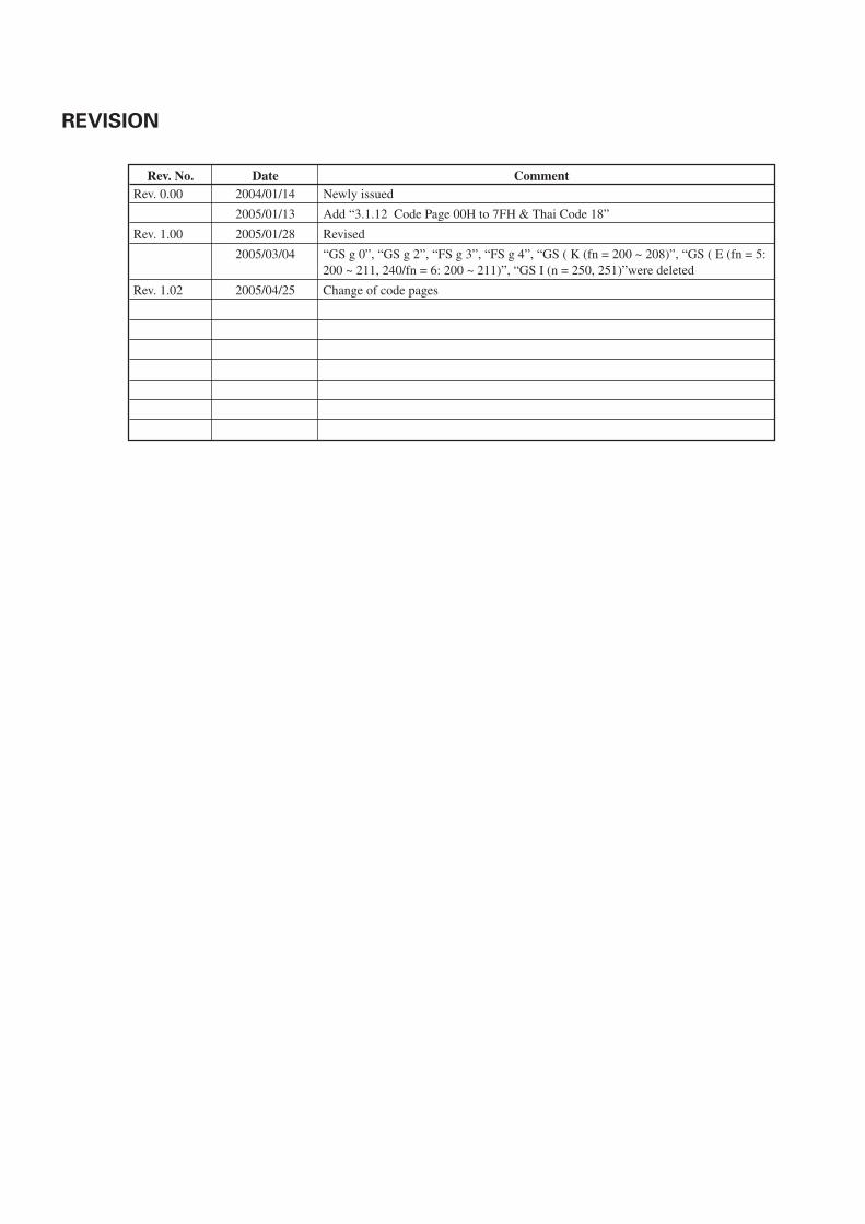
Rev. No. Date CommentRev. 0.00 2004/01/14 Newly issued
2005/01/13 Add “3.1.12 Code Page 00H to 7FH & Thai Code 18”
Rev. 1.00 2005/01/28 Revised
2005/03/04 “GS g 0”, “GS g 2”, “FS g 3”, “FS g 4”, “GS ( K (fn = 200 ~ 208)”, “GS ( E (fn = 5:200 ~ 211, 240/fn = 6: 200 ~ 211)”, “GS I (n = 250, 251)”were deleted
Rev. 1.02 2005/04/25 Change of code pages
REVISION
— i —
TABLE OF CONTENTS1. OUTLINE .............................................................................................................................................. 1
1.1 Operation Mode ............................................................................................................................................ 11.2 Character Set ................................................................................................................................................. 11.3 Control Commands ....................................................................................................................................... 1
1.3.1 Control Command Details .................................................................................................................. 11.3.2 How to Send Control Commands ...................................................................................................... 1
2. CONTROL COMMANDS ..................................................................................................................... 2
2.1 ESC/POS Command List ............................................................................................................................... 22.1.1 Description of Items ............................................................................................................................ 6
2.2 Command Details .......................................................................................................................................... 72.2.1 Print Control Commands .................................................................................................................... 7
LF .............................................................................................................................................................. 7CR ............................................................................................................................................................. 8FF .............................................................................................................................................................. 9ESC FF .................................................................................................................................................... 10ESC J n ................................................................................................................................................... 10ESC d n .................................................................................................................................................. 11
2.2.2 Print Character Commands .............................................................................................................. 12CAN ........................................................................................................................................................ 12ESC SP n ................................................................................................................................................ 13ESC ! n ................................................................................................................................................... 14ESC % n ................................................................................................................................................. 16ESC & s n m [a[p]s×a] m–n+1 .............................................................................................................. 17ESC – n ................................................................................................................................................... 18ESC ? n ................................................................................................................................................... 19ESC E n .................................................................................................................................................. 20ESC G n .................................................................................................................................................. 21ESC M n ................................................................................................................................................. 22ESC R n .................................................................................................................................................. 22ESC V n .................................................................................................................................................. 23ESC t n ................................................................................................................................................... 24ESC { n ................................................................................................................................................... 25GS ! n ..................................................................................................................................................... 26GS B n .................................................................................................................................................... 27GS b n .................................................................................................................................................... 28
2.2.3 Print Position Commands................................................................................................................. 29HT ........................................................................................................................................................... 29ESC $ n1 n2 ........................................................................................................................................... 30ESC D [n]k NULL ................................................................................................................................... 31ESC T n .................................................................................................................................................. 32ESC W xL xH yL yH dxL dxH dyL dyH ................................................................................................. 33ESC \ nL nH ............................................................................................................................................ 34ESC a n ................................................................................................................................................... 35GS $ nL nH............................................................................................................................................. 36GS L nL nH............................................................................................................................................. 37GS T n .................................................................................................................................................... 38GS W nL nH ........................................................................................................................................... 39GS \ nL nH.............................................................................................................................................. 41
2.2.4 Line Feed Span Commands ............................................................................................................. 42ESC 2 ...................................................................................................................................................... 42ESC 3 n ................................................................................................................................................... 43
— ii —
2.2.5 Bit Image Commands ....................................................................................................................... 44ESC * m n1 n2 [d] k ............................................................................................................................... 44GS * n1 n2 [d]n1×n2×8 ......................................................................................................................... 46GS / m .................................................................................................................................................... 48GS v 0 m xL xH yL yH d1...dk ............................................................................................................... 49
2.2.6 Status Commands............................................................................................................................. 50DLE EOT n.............................................................................................................................................. 50ESC v (At Serial I/F Selection) .............................................................................................................. 54GS a n .................................................................................................................................................... 55GS r n ..................................................................................................................................................... 58
2.2.7 Paper Detecting Commands ............................................................................................................ 59ESC c 3 n ................................................................................................................................................ 59ESC c 4 n ................................................................................................................................................ 60
2.2.8 Panel Switch Commands ................................................................................................................. 61ESC c 5 n ................................................................................................................................................ 61
2.2.9 Macro Commands............................................................................................................................. 62GS : ......................................................................................................................................................... 62GS ^ n1 n2 n3 ........................................................................................................................................ 63
2.2.10 Cutter Commands ........................................................................................................................... 64ESC i ....................................................................................................................................................... 64ESC m .................................................................................................................................................... 65GS V m ......... (1)GS V m n ...... (2) ................................................................................................................................... 66
2.2.11 Bar Code Commands ...................................................................................................................... 67GS H n .................................................................................................................................................... 67GS f n ..................................................................................................................................................... 69GS h n .................................................................................................................................................... 70GS k m [d1...dk] NULL ......... (1)GS k m n [d1...dn] ................ (2) ........................................................................................................... 71GS w n ................................................................................................................................................... 77
2.2.12 Commands for Non-volatile Memory ........................................................................................... 78GS ( C pL pH m fn b[c1 c2][d1...dk] ..................................................................................................... 78GS ( C pL pH m fn b c1 c2 .................................................................................................................... 79
fn = 0, 48: Function 0 Erasing Specified Record ............................................................................ 79GS ( C pL pH m fn b c1 c2 d1...dk ........................................................................................................ 79
fn = 1, 49: Function 1 Storing Data to Specified Record ............................................................... 79GS ( C pL pH m fn b c1 c2 .................................................................................................................... 80
fn = 2, 50: Function 2 Sending Data Stored in Specified Record.................................................. 80GS ( C pL pH m fn b .............................................................................................................................. 81
fn = 3, 51: Function 3 Sending Use Amount .................................................................................. 81GS ( C pL pH m fn b .............................................................................................................................. 81
fn = 4, 52: Function 4 Sending Remaining Capacity ...................................................................... 81GS ( C pL pH m fn b .............................................................................................................................. 82
fn = 5, 53: Function 5 Sending Key Code List of Stored Record ................................................... 82GS ( C pL pH m fn b [d1 d2 d3] ............................................................................................................ 83
fn = 6, 54: Function 6 Erasing All User NV Memory Area in a Lump ........................................... 83FS p n m................................................................................................................................................. 84FS q n [xL xH yL yH d1…dk]1…[xL xH yL yH d1…dk]n ..................................................................... 85
— iii —
2.2.13 Printer Function Setting Commands ............................................................................................. 87GS ( E pL pH fn [...] ............................................................................................................................... 87GS ( E pL pH fn d1 d2 ........................................................................................................................... 88
fn = 1: Function 1 Transferring to Printer Function Setting Mode ................................................ 88GS ( E pL pH fn d1 d2 d3 ...................................................................................................................... 88
fn = 2: Function 2 End of Printer Function Setting Mode .............................................................. 88GS ( E pL pH fn [a1 b18...b11]...[ak bk8...bk1] ..................................................................................... 89
fn = 3: Function 3 Setting Memory Switch Value .......................................................................... 89GS ( E pL pH fn a ................................................................................................................................... 91
fn = 4: Function 4 Sending the Set Memory Switch Value ........................................................... 91GS ( E pL pH fn[a1 n1L n1H]...[ak nkL nkH] ......................................................................................... 92
fn = 5: Function 5 Setting Customized Value ................................................................................. 92GS ( E pL pH fn a ................................................................................................................................... 95
fn = 6: Function 6 Sending the Set Customized Value .................................................................. 95GS ( E pL pH fn a d1 d2 ........................................................................................................................ 98
fn = 7: Function 7 Copying User-defined Page .............................................................................. 98GS ( E pL pH fn y c1 c2[x d1...d(y×x)]k ................................................................................................ 99
fn = 8: Function 8 Defining Data by the Column Format to Character Code Page ofWork Area .......................................................................................................................................... 99
GS ( E pL pH fn x c1 c2[y d1...d(y×x)]k .............................................................................................. 100fn = 9: Function 9 Defining Data in the Raster Format to the Character Code Page ofWork Area ........................................................................................................................................ 100
GS ( E pL pH fn c1 c2 .......................................................................................................................... 101fn = 10: Function 10 Erasing Data of Character Code Page Data in Work Area ........................ 101
GS ( E pL pH fn a d1...dk ..................................................................................................................... 102fn = 11: Function 11 Setting Communication Conditions of Serial Interface ............................ 102
GS ( E pL pH fn a ................................................................................................................................. 103fn = 12: Function 12 Sending the Set Communication Conditions of Serial Interface ............. 103
GS ( E pL pH fn d1 d2 d3 .................................................................................................................... 104fn = 48: Function 48 Erasing Paper Layout ................................................................................... 104
GS ( E pL pH fn[a1]; [bLbH] ; [cLcH] ; [dLdH] ; [eLeH] ; [fLfH] ;[gLgH] ; [hLhH]; ................................................................................................................................... 104
fn = 49: Function 49 Setting Paper Layout ................................................................................... 104GS ( E pL pH fn n ................................................................................................................................. 106
fn = 50: Function 50 Sending Paper Layout Information ............................................................ 106GS ( E pL pH fn a ................................................................................................................................. 108
fn = 255: Function 255 Setting All Contents Set by Printer Function Setting Mode to theState at Shipment ............................................................................................................................ 108
GS ( K pL pH fn m ............................................................................................................................... 109GS ( K pL pH fn m ............................................................................................................................... 109
fn = 48: Function 48 Setting Print Control Mode ......................................................................... 109GS ( K pL pH fn m ............................................................................................................................... 110
fn = 49: Function 49 Setting Printing Density............................................................................... 110GS ( K pL pH fn m ............................................................................................................................... 111
fn = 50: Function 50 Setting Printing Speed................................................................................. 111GS ( K pL pH fn m ............................................................................................................................... 112
fn = 97: Function 97 Setting Number of Divisions for Head Conducting................................... 112GS ( M pL pH fn m .............................................................................................................................. 113GS ( M pL pH fn m .............................................................................................................................. 114
fn = 1, 49: Function 1 ....................................................................................................................... 114GS ( M pL pH fn m .............................................................................................................................. 114
fn = 2, 50: Function 2 ....................................................................................................................... 114GS ( M pL pH fn m fn = 3, 51 ............................................................................................................ 115
fn = 3, 51: Function 3 ....................................................................................................................... 115GS ( N pL pH fn m ............................................................................................................................... 116GS ( N pL pH fn m ............................................................................................................................... 116
fn = 48: Function 48 ......................................................................................................................... 116
— iv —
2.2.14 Special Commands ....................................................................................................................... 117ESC n n ................................................................................................................................................ 117ESC Y n1 n2 ......................................................................................................................................... 118GS R 0 .................................................................................................................................................. 118GS R 1 n ............................................................................................................................................... 119GS S ..................................................................................................................................................... 119FS ( L pL pH fn m ................................................................................................................................ 120FS ( L pL pH fn m ................................................................................................................................ 121
fn = 48: Function 48 Sending Position Information .................................................................... 121FS ( L pL pH fn m ................................................................................................................................ 122
fn = 66: Function 66 Executing Paper Feeding to Cut Position ................................................... 122FS ( L pL pH fn m ................................................................................................................................ 122
fn = 67: Function 67 Executing Paper Feeding to Initial Position ............................................... 1222.2.15 Other Commands .......................................................................................................................... 123
DLE ENQ n ........................................................................................................................................... 123DLE DC4 fn m t (Specification of fn = 8) ............................................................................................ 124ESC = n .............................................................................................................................................. 125ESC @ ................................................................................................................................................. 126ESC L ................................................................................................................................................... 127ESC S .................................................................................................................................................. 128ESC RS ................................................................................................................................................ 128GS ( A pL pH n m ............................................................................................................................... 129GS I n ................................................................................................................................................. 130GS P x y ............................................................................................................................................ 132GS ( L pL pH m fn [parameter]GS 8 L p1 p2 p3 p4 m fn [parameter] ................................................................................................ 133GS ( L pL pH m fn ................................................................................................................................ 134
fn = 0, 48: Function 48 Sending NV Graphics Memory Capacity ............................................... 134GS ( L pL pH m fn ................................................................................................................................ 134
fn = 2, 50: Function 50 Printing Graphics Data Stored in Print Buffer........................................ 134GS ( L pL pH m fn ................................................................................................................................ 135
fn = 3, 51: Function 51 Sending the Remaining Amount of NV Graphics Memory .................. 135GS ( L pL pH m fn d1 d2 ..................................................................................................................... 135
fn = 64: Function 64 Sending Key Code List of Defined NV Graphics........................................ 135GS ( L pL pH m fn d1 d2 d3 ................................................................................................................ 137
fn = 65: Function 65 Erasing All Data of NV Graphics in a Lump ............................................... 137GS ( L pL pH m fn kc1 kc2 .................................................................................................................. 137
fn = 66: Function 66 Erasing Specified NV Graphics Data .......................................................... 137GS ( L pL pH m fn a kc1 kc2 b xL xH yL yH [ c d1…dk]1…[c d1…dk]b ........................................... 138
fn = 67: Function 67 Defining Raster Type Graphics Data to NV Memory ................................. 138GS ( L pL pH m fn kc1 kc2 x y ............................................................................................................ 139
fn = 69: Function 69 Printing Specified Graphics......................................................................... 139GS ( L pL pH m fn a bx by c xL xH yL yH d1…dk ............................................................................. 140
fn = 112: Function 112 Storing Raster Type Graphics Data to Print Buffer ................................ 140GS C 0 n m........................................................................................................................................... 141GS C 1 aL aH bL bH n r ....................................................................................................................... 142GS C 2 nL nH ....................................................................................................................................... 142GS C ; sa ; sb ; sn ; sr ; sc; ................................................................................................................... 143GS c ...................................................................................................................................................... 143
— v —
3. CHARACTER CODE TABLE ............................................................................................................. 144
3.1 Code Page .................................................................................................................................................. 1443.1.1 Code Page 00H to 7FH & PC437 (USA, Europe Standard) ........................................................... 1443.1.2 Code Page 00H to 7FH & Katakana ................................................................................................ 1453.1.3 Code Page 00H to 7FH & PC850 (Multilingual) ............................................................................. 1463.1.4 Code Page 00H to 7FH & PC860 (Portuguese) .............................................................................. 1473.1.5 Code Page 00H to 7FH & PC863 (Canadian-French)..................................................................... 1483.1.6 Code Page 00H to 7FH & PC865 (Nordic) ...................................................................................... 1493.1.7 Code Page 00H to 7FH & PC852 (Eastern Europe) ....................................................................... 1503.1.8 Code Page 00H to 7FH & PC866 (Russian) .................................................................................... 1513.1.9 Code Page 00H to 7FH & PC857 (Turkish) ..................................................................................... 1523.1.10 Code Page 00H to 7FH & PC864 (Arabic) .................................................................................... 1533.1.11 Code Page 00H to 7FH & WPC1252 ............................................................................................. 1543.1.12 Code Page 00H to 7FH & Thai Code 18 ....................................................................................... 155
3.2 International Character Code Table ......................................................................................................... 156
4. APPENDIX ........................................................................................................................................ 157
4.1 Explanation on PAGE MODE .................................................................................................................... 1574.1.1 Overview .......................................................................................................................................... 1574.1.2 Values Set by Each Command in STANDARD MODE and PAGE MODE .................................... 1574.1.3 Mapping of Print Data in the Print Area ........................................................................................ 1584.1.4 Example of Using PAGE MODE ..................................................................................................... 159
4.2 Bidirectional Parallel Interface ................................................................................................................. 1614.2.1 Parallel Interface Communication Mode....................................................................................... 1614.2.2 Interfacing Phases ........................................................................................................................... 1614.2.3 Negotiation ...................................................................................................................................... 162
4.3 Identification of Send Status .................................................................................................................... 1674.4 Memory Switch ......................................................................................................................................... 168
4.4.1 Memory Switches ........................................................................................................................... 1684.4.2 Details of Memory Switches .......................................................................................................... 169
— 1 —
1. OUTLINE
1.1 Operation Mode
PPU-700 has ESC/POSTM as control commands.
1.2 Character Set
All print data sent from the host computer to the printer are automatically converted to one-byte alphanumericor katakana characters (ANK) or two-byte Kanji corresponding to the characters and symbols.
NOTE: For the contents of character set, refer to “3. Character Code Table” of this document.
1.3 Control Commands
1.3.1 Control Command Details
Control Commands are used for controlling the operations of the printer such as starting/stopping of printing,line feeding, paper feeding, etc. They control all functions related to printing, such as type of characters,enlargement of characters or setting of format.
1.3.2 How to Send Control Commands
Some methods are available for sending Control Commands from the host computer to the printer. Here, amethod of sending by BASIC programming is explained.
Example 1
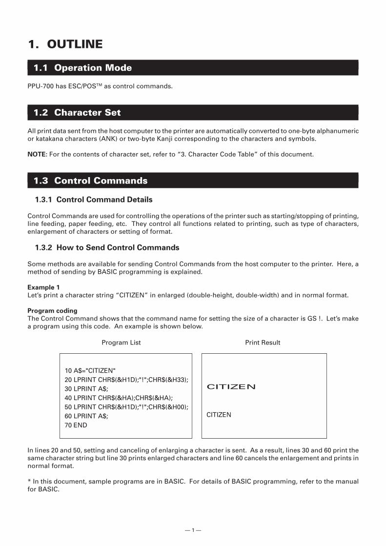
Let’s print a character string “CITIZEN” in enlarged (double-height, double-width) and in normal format.
Program coding
The Control Command shows that the command name for setting the size of a character is GS !. Let’s makea program using this code. An example is shown below.
Program List Print Result
10 A$="CITIZEN"20 LPRINT CHR$(&H1D);"!";CHR$(&H33);30 LPRINT A$;40 LPRINT CHR$(&HA);CHR$(&HA);50 LPRINT CHR$(&H1D);"!";CHR$(&H00);60 LPRINT A$;70 END
CITIZEN
CITIZEN
In lines 20 and 50, setting and canceling of enlarging a character is sent. As a result, lines 30 and 60 print thesame character string but line 30 prints enlarged characters and line 60 cancels the enlargement and prints innormal format.
* In this document, sample programs are in BASIC. For details of BASIC programming, refer to the manualfor BASIC.
— 2 —
2. CONTROL COMMANDS
2.1 ESC/POS Command List
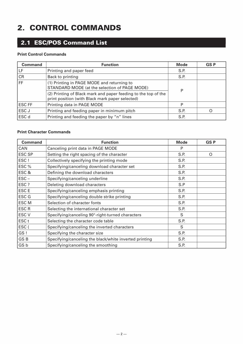
Print Control Commands
Command Function Mode GS P
LF Printing and paper feed S.P.CR Back to printing S.P.FF (1) Printing in PAGE MODE and returning to
STANDARD MODE (at the selection of PAGE MODE)P
(2) Printing of Black mark and paper feeding to the top of theprint position (with Black mark paper selected)
ESC FF Printing data in PAGE MODE PESC J Printing and feeding paper in minimum pitch S.P. OESC d Printing and feeding the paper by “n” lines S.P.
Print Character Commands
Command Function Mode GS P
CAN Canceling print data in PAGE MODE PESC SP Setting the right spacing of the character S.P. OESC ! Collectively specifying the printing mode S.P.ESC % Specifying/canceling download character set S.P.ESC & Defining the download characters S.P.ESC – Specifying/canceling underline S.P.ESC ? Deleting download characters S.PESC E Specifying/canceling emphasis printing S.P.ESC G Specifying/canceling double strike printing S.P.ESC M Selection of character fonts S.P.ESC R Selecting the international character set S.P.ESC V Specifying/canceling 90°-right-turned characters SESC t Selecting the character code table S.P.ESC { Specifying/canceling the inverted characters SGS ! Specifying the character size S.P.GS B Specifying/canceling the black/white inverted printing S.P.GS b Specifying/canceling the smoothing S.P.
— 3 —
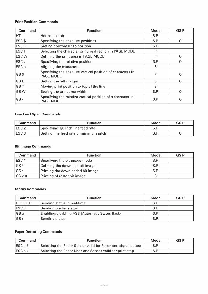
Print Position Commands
Command Function Mode GS P
HT Horizontal tab S.P.ESC $ Specifying the absolute positions S.P. OESC D Setting horizontal tab position S.P.ESC T Selecting the character printing direction in PAGE MODE PESC W Defining the print area in PAGE MODE P OESC \ Specifying the relative position S.P. OESC a Aligning the characters S
GS $Specifying the absolute vertical position of characters in
P OPAGE MODEGS L Setting the left margin S OGS T Moving print position to top of the line SGS W Setting the print area width S.P. O
GS \Specifying the relative vertical position of a character in
S.P. OPAGE MODE
Line Feed Span Commands
Command Function Mode GS P
ESC 2 Specifying 1/6-inch line feed rate S.P.ESC 3 Setting line feed rate of minimum pitch S.P. O
Bit Image Commands
Command Function Mode GS P
ESC * Specifying the bit image mode S.P.GS * Defining the download bit image S.P.GS / Printing the downloaded bit image S.P.GS v 0 Printing of raster bit image S
Status Commands
Command Function Mode GS P
DLE EOT Sending status in real-time S.P.ESC v Sending printer status S.P.GS a Enabling/disabling ASB (Automatic Status Back) S.P.GS r Sending status S.P.
Paper Detecting Commands
Command Function Mode GS P
ESC c 3 Selecting the Paper Sensor valid for Paper-end signal output S.P.ESC c 4 Selecting the Paper Near-end Sensor valid for print stop S.P.
— 4 —
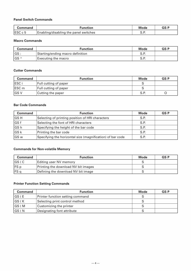
Panel Switch Commands
Command Function Mode GS P
ESC c 5 Enabling/disabling the panel switches S.P.
Macro Commands
Command Function Mode GS P
GS : Starting/ending macro definition S.P.GS ^ Executing the macro S.P.
Cutter Commands
Command Function Mode GS P
ESC i Full cutting of paper SESC m Full cutting of paper SGS V Cutting the paper S.P. O
Bar Code Commands
Command Function Mode GS P
GS H Selecting of printing position of HRI characters S.P.GS f Selecting the font of HRI characters S.P.GS h Specifying the height of the bar code S.P.GS k Printing the bar code S.P.GS w Specifying the horizontal size (magnification) of bar code S.P.
Commands for Non-volatile Memory
Command Function Mode GS P
GS ( C Editing user NV memory SFS p Printing the download NV bit images SFS q Defining the download NV bit image S
Printer Function Setting Commands
Command Function Mode GS P
GS ( E Printer function setting command SGS ( K Selecting print control method SGS ( M Customizing the printer SGS ( N Designating font attribute S
— 5 —
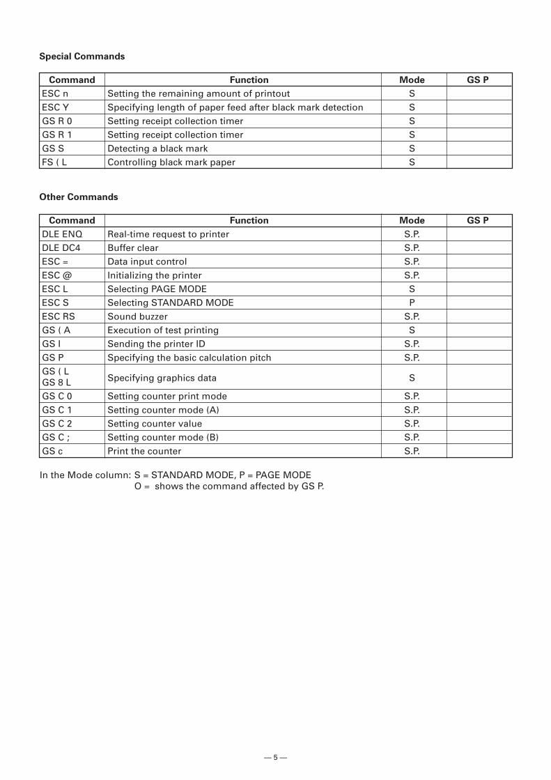
Special Commands
Command Function Mode GS P
ESC n Setting the remaining amount of printout SESC Y Specifying length of paper feed after black mark detection SGS R 0 Setting receipt collection timer SGS R 1 Setting receipt collection timer SGS S Detecting a black mark SFS ( L Controlling black mark paper S
Other Commands
Command Function Mode GS P
DLE ENQ Real-time request to printer S.P.DLE DC4 Buffer clear S.P.ESC = Data input control S.P.ESC @ Initializing the printer S.P.ESC L Selecting PAGE MODE SESC S Selecting STANDARD MODE PESC RS Sound buzzer S.P.GS ( A Execution of test printing SGS I Sending the printer ID S.P.GS P Specifying the basic calculation pitch S.P.GS ( L
Specifying graphics data SGS 8 LGS C 0 Setting counter print mode S.P.GS C 1 Setting counter mode (A) S.P.GS C 2 Setting counter value S.P.GS C ; Setting counter mode (B) S.P.GS c Print the counter S.P.
In the Mode column: S = STANDARD MODE, P = PAGE MODEO = shows the command affected by GS P.
— 6 —
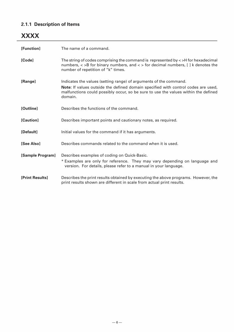
2.1.1 Description of Items
XXXX
[Function] The name of a command.
[Code] The string of codes comprising the command is represented by < >H for hexadecimalnumbers, < >B for binary numbers, and < > for decimal numbers, [ ] k denotes thenumber of repetition of “k” times.
[Range] Indicates the values (setting range) of arguments of the command.Note: If values outside the defined domain specified with control codes are used,malfunctions could possibly occur, so be sure to use the values within the defineddomain.
[Outline] Describes the functions of the command.
[Caution] Describes important points and cautionary notes, as required.
[Default] Initial values for the command if it has arguments.
[See Also] Describes commands related to the command when it is used.
[Sample Program] Describes examples of coding on Quick-Basic.* Examples are only for reference. They may vary depending on language and
version. For details, please refer to a manual in your language.
[Print Results] Describes the print results obtained by executing the above programs. However, theprint results shown are different in scale from actual print results.
— 7 —
2.2 Command Details
2.2.1 Print Control Commands
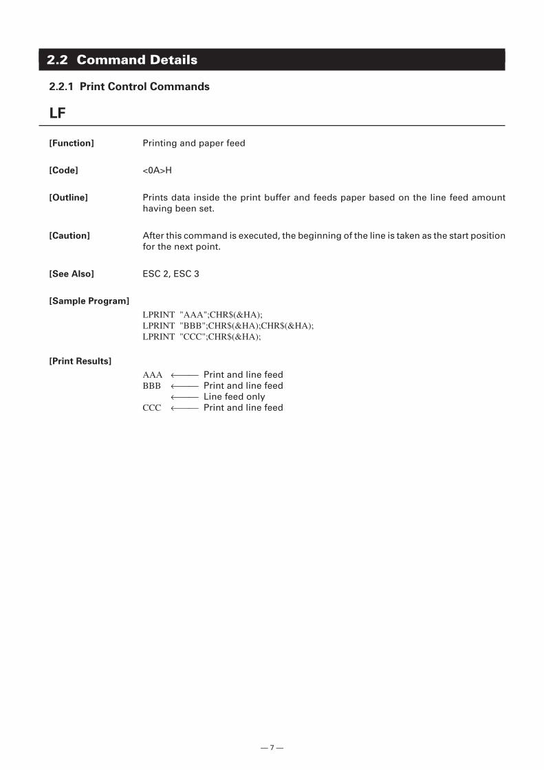
LF
[Function] Printing and paper feed
[Code] <0A>H
[Outline] Prints data inside the print buffer and feeds paper based on the line feed amounthaving been set.
[Caution] After this command is executed, the beginning of the line is taken as the start positionfor the next point.
[See Also] ESC 2, ESC 3
[Sample Program]
LPRINT "AAA";CHR$(&HA);LPRINT "BBB";CHR$(&HA);CHR$(&HA);LPRINT "CCC";CHR$(&HA);
[Print Results]
AAA ← Print and line feedBBB ← Print and line feed
← Line feed onlyCCC ← Print and line feed
— 8 —
CR
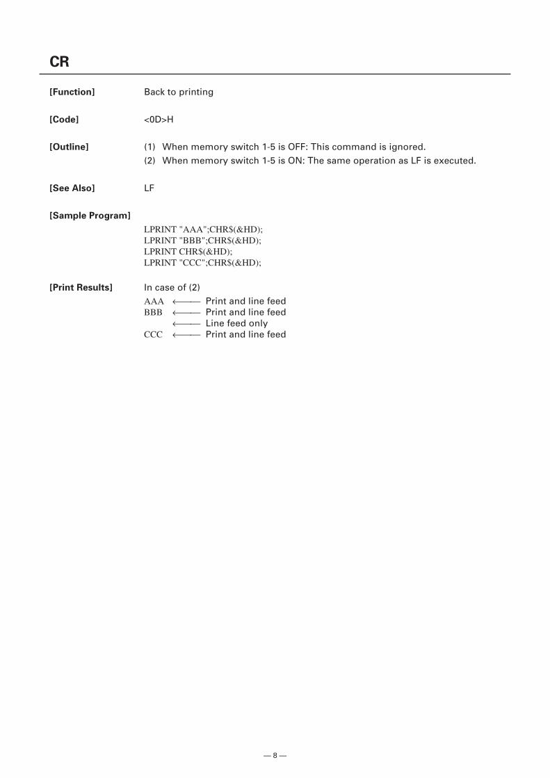
[Function] Back to printing
[Code] <0D>H
[Outline] (1) When memory switch 1-5 is OFF: This command is ignored.(2) When memory switch 1-5 is ON: The same operation as LF is executed.
[See Also] LF
[Sample Program]
LPRINT "AAA";CHR$(&HD);LPRINT "BBB";CHR$(&HD);LPRINT CHR$(&HD);LPRINT "CCC";CHR$(&HD);
[Print Results] In case of (2)AAA ← Print and line feedBBB ← Print and line feed
← Line feed onlyCCC ← Print and line feed
— 9 —
FF
[Function] (1) Printing in PAGE MODE and returning to STANDARD MODE (at the selection ofPAGE MODE)
(2) Printing of Black mark and paper feeding to the top of the print position (withBlack mark paper selected)
[Code] <0C>H
(1) At selection of PAGE MODE
[Outline] Executes a batch printout of the data mapped in the entire print area, and then returnsto STANDARD MODE.
[Caution] • All mapped data is erased after printout.• The print area set up by ESC W is initialized.• This command does not execute a paper cut.• After this command is executed, the beginning of the line is taken as the start
position for the next print.• This command is only effective when the PAGE MODE is selected.
[See Also] Appendix 4.1.4 “Example of Using PAGE MODE”ESC FF, ESC L, ESC S
(2) At selection of Black mark paper (valid only for Black mark specification)
[Outline] This command prints the data in the printer buffer and searches for the head of thenext Black mark (Black mark position)
[Caution] • This command does not execute a paper cut.• After this command is executed, the beginning of the line is taken as the start
position for the next print.
[See Also] GS FF
— 10 —
ESC FF
[Function] Printing data in PAGE MODE
[Code] <1B>H<0C>H
[Outline] Executes a batch printout of the data mapped in the entire print area in PAGE MODE.
[Caution] • This command is only effective when PAGE MODE is selected.• Mapped data, as well as the ESC T and ESC W settings, and the character mapping
position are held even after printing.
[See Also] Appendix 4.1 “Explanation on PAGE MODE”FF, ESC L, ESC S
ESC J n
[Function] Printing and feeding paper in minimum pitch
[Code] <1B>H<4A>H<n>
[Range] 0 n 255
[Outline] Prints the data held in the print buffer and feeds paper by [n × basic calculation pitch]inches.
[Caution] • After this command is executed, the beginning of the line is taken as the start positionfor the next print.
• The line feed width can be set separately for the STANDARD and PAGE MODES.• This command does not affect the line feed width defined by ESC 2 or ESC 3.• The basic calculation pitch is set by GS P.• Fractions resulting from calculation are corrected with the minimum pitch of the
mechanism, and the remainder is omitted.• In STANDARD MODE, this command uses the vertical (paper feed direction) basic
calculation pitch (y).• In PAGE MODE, this command acts differently depending on the start point:
(1) If the start point specified by ESC T is top left or bottom right, the commanduses the vertical (paper feed direction) basic calculation pitch (y).
(2) If the start point specified by ESC T is top right or bottom left, the commanduses the horizontal (perpendicular to the paper feed direction) basic calculationpitch (x).
• The maximum settable line feed width is 1016 mm (40 inches). A setting greaterthan this maximum is trimmed to the maximum.
[Default] The initial value is not defined.
[Sample Program] Refer to Sample Program and Print Results for ESC 2.
— 11 —
ESC d n
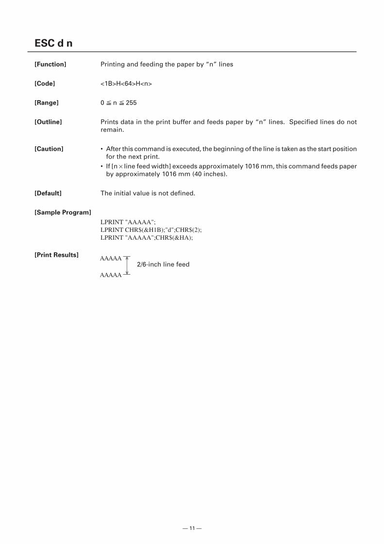
[Function] Printing and feeding the paper by “n” lines
[Code] <1B>H<64>H<n>
[Range] 0 n 255
[Outline] Prints data in the print buffer and feeds paper by “n” lines. Specified lines do notremain.
[Caution] • After this command is executed, the beginning of the line is taken as the start positionfor the next print.
• If [n × line feed width] exceeds approximately 1016 mm, this command feeds paperby approximately 1016 mm (40 inches).
[Default] The initial value is not defined.
[Sample Program]
LPRINT "AAAAA";LPRINT CHR$(&H1B);"d";CHR$(2);LPRINT "AAAAA";CHR$(&HA);
[Print Results]
2/6-inch line feedAAAAA
AAAAA
<
<
— 12 —
2.2.2 Print Character Commands
CAN
[Function] Canceling print data in PAGE MODE
[Code] <18>H
[Outline] Erases all data contained in the currently effective print area in PAGE MODE.
[Caution] • This command is only effective when PAGE MODE is selected.• If the previously established print area overlaps the currently effective print area,
the overlapped data in the previously established area will be erased.
[See Also] Appendix 4.1 “Explanation on PAGE MODE”ESC L, ESC W
— 13 —
ESC SP n
[Function] Setting the right spacing of the character
[Code] <1B>H<20>H<n>
[Range] 0 n 255
[Outline] Sets the right spacing of character to [n × basic calculation pitch] inches.
[Caution] • If the horizontal magnification of character is 2 or more, the right spacing increaseswith the magnification.
• Does not affect Kanji.• The right spacing can be set separately for the STANDARD and PAGE MODES.• The basic calculation pitch is set by GS P. Once defined, the right spacing is not
changed if the basic calculation pitch is changed by GS P.• Fractions resulting from calculation are corrected with the minimum pitch of the
mechanism, and the remainder is omitted.• In STANDARD MODE, this command uses the horizontal basic calculation pitch (x).• In PAGE MODE, the basic calculation pitch used by this command depends on the
start point:(1) If the start point specified by ESC T is top left or bottom right, the command
uses the horizontal basic calculation pitch (x).(2) If the start point specified by ESC T is top right or bottom left, the command
uses the vertical basic calculation pitch (y).• The maximum right spacing is capable of approximately 31.906 mm (255/203
inches). A setting greater than this maximum is trimmed to the maximum.
[Default] n = 0
[See Also] GS P
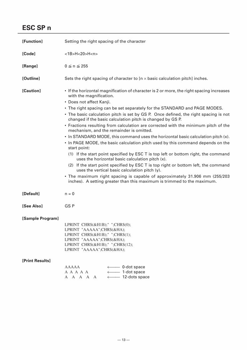
[Sample Program]
LPRINT CHR$(&H1B);" ";CHR$(0);LPRINT "AAAAA";CHR$(&HA);LPRINT CHR$(&H1B);" ";CHR$(1);LPRINT "AAAAA";CHR$(&HA);LPRINT CHR$(&H1B);" ";CHR$(12);LPRINT "AAAAA";CHR$(&HA);
[Print Results]
AAAAA ← 0-dot spaceA A A A A ← 1-dot spaceA A A A A ← 12-dots space
— 14 —
ESC ! n
[Function] Collectively specifying the printing mode
[Code] <1B>H<21>H<n>
[Range] 0 n 255
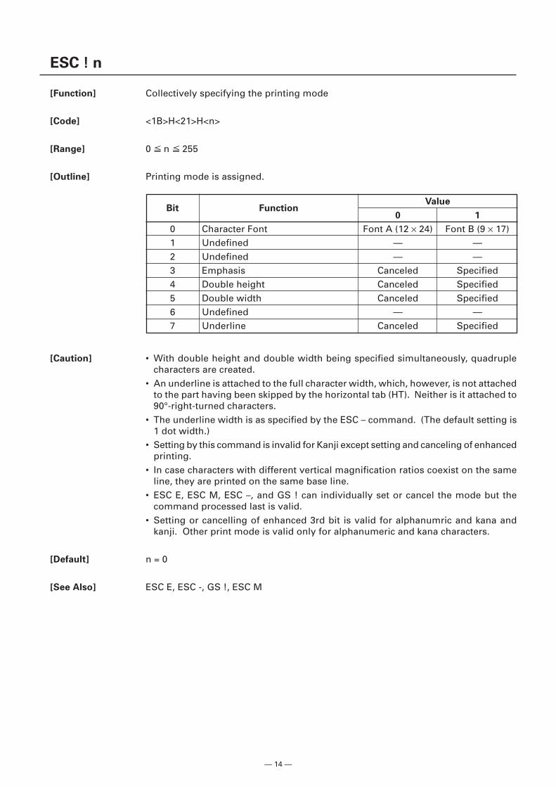
[Outline] Printing mode is assigned.
[Caution] • With double height and double width being specified simultaneously, quadruplecharacters are created.
• An underline is attached to the full character width, which, however, is not attachedto the part having been skipped by the horizontal tab (HT). Neither is it attached to90°-right-turned characters.
• The underline width is as specified by the ESC – command. (The default setting is1 dot width.)
• Setting by this command is invalid for Kanji except setting and canceling of enhancedprinting.
• In case characters with different vertical magnification ratios coexist on the sameline, they are printed on the same base line.
• ESC E, ESC M, ESC –, and GS ! can individually set or cancel the mode but thecommand processed last is valid.
• Setting or cancelling of enhanced 3rd bit is valid for alphanumric and kana andkanji. Other print mode is valid only for alphanumeric and kana characters.
[Default] n = 0
[See Also] ESC E, ESC -, GS !, ESC M
Bit FunctionValue
0 1
0 Character Font Font A (12 × 24) Font B (9 × 17)1 Undefined — —2 Undefined — —3 Emphasis Canceled Specified4 Double height Canceled Specified5 Double width Canceled Specified6 Undefined — —7 Underline Canceled Specified
— 15 —
[Sample Program]
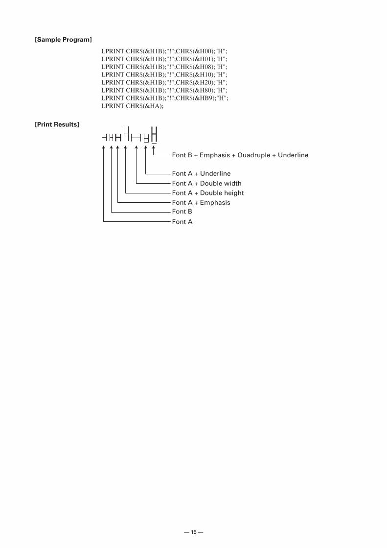
LPRINT CHR$(&H1B);"!";CHR$(&H00);"H";LPRINT CHR$(&H1B);"!";CHR$(&H01);"H";LPRINT CHR$(&H1B);"!";CHR$(&H08);"H";LPRINT CHR$(&H1B);"!";CHR$(&H10);"H";LPRINT CHR$(&H1B);"!";CHR$(&H20);"H";LPRINT CHR$(&H1B);"!";CHR$(&H80);"H";LPRINT CHR$(&H1B);"!";CHR$(&HB9);"H";LPRINT CHR$(&HA);
[Print Results]
Font A + EmphasisFont A + Double height
Font A
Font B
Font B + Emphasis + Quadruple + Underline
Font A + Underline
Font A + Double width
— 16 —
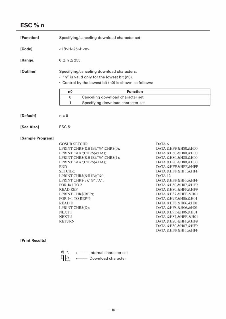
ESC % n
[Function] Specifying/canceling download character set
[Code] <1B>H<25>H<n>
[Range] 0 n 255
[Outline] Specifying/canceling download characters.• “n” is valid only for the lowest bit (n0).• Control by the lowest bit (n0) is shown as follows:
[Default] n = 0
[See Also] ESC &
[Sample Program]
GOSUB SETCHR DATA 6LPRINT CHR$(&H1B);"%";CHR$(0); DATA &HFF,&H80,&H00LPRINT "@A";CHR$(&HA); DATA &H80,&H80,&H00LPRINT CHR$(&H1B);"%";CHR$(1); DATA &H80,&H80,&H00LPRINT "@A";CHR$(&HA); DATA &H80,&H80,&H00END DATA &HFF,&HFF,&HFFSETCHR: DATA &HFF,&HFF,&HFFLPRINT CHR$(&H1B);"&"; DATA 12LPRINT CHR$(3);"@";"A"; DATA &HFF,&HFF,&HFFFOR J=1 TO 2 DATA &H80,&H07,&HF9READ REP DATA &H80,&HFF,&HF9LPRINT CHR$(REP); DATA &H87,&HFE,&H01FOR I=1 TO REP*3 DATA &H9F,&H06,&H01READ D DATA &HF8,&H06,&H01LPRINT CHR$(D); DATA &HF8,&H06,&H01NEXT I DATA &H9F,&H06,&H01NEXT J DATA &H87,&HFE,&H01RETURN DATA &H80,&HFF,&HF9
DATA &H80,&H07,&HF9DATA &HFF,&HFF,&HFF
[Print Results]
n0 Function
0 Canceling download character set1 Specifying download character set
← Internal character set
← Download character
— 17 —
ESC & s n m [a[p]s×a] m–n+1
[Function] Defining the download characters
[Code] <1B>H<26>H<s>H<n>H<m>H[<a>H<p1>H<p2><ps×a>]m-n+1
[Range] s = 3 (Font A, B)s = 2 (Font C)32 n m 1260 a 12 (Font A)0 a 9 (Font B)0 a 8 (Font C)0 p1 ⋅ ⋅ ps × a 255
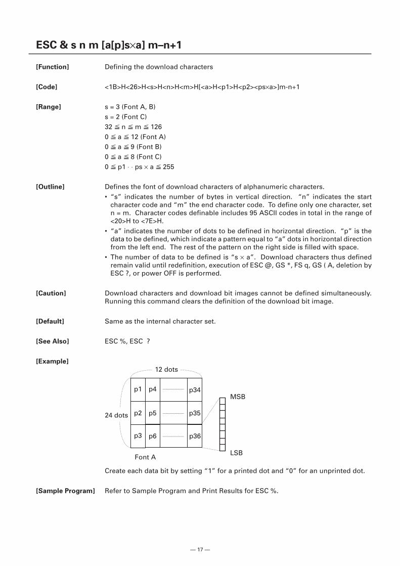
[Outline] Defines the font of download characters of alphanumeric characters.• “s” indicates the number of bytes in vertical direction. “n” indicates the start
character code and “m” the end character code. To define only one character, setn = m. Character codes definable includes 95 ASCII codes in total in the range of<20>H to <7E>H.
• “a” indicates the number of dots to be defined in horizontal direction. “p” is thedata to be defined, which indicate a pattern equal to “a” dots in horizontal directionfrom the left end. The rest of the pattern on the right side is filled with space.
• The number of data to be defined is “s × a”. Download characters thus definedremain valid until redefinition, execution of ESC @, GS *, FS q, GS ( A, deletion byESC ?, or power OFF is performed.
[Caution] Download characters and download bit images cannot be defined simultaneously.Running this command clears the definition of the download bit image.
[Default] Same as the internal character set.
[See Also] ESC %, ESC ?
[Example]
Font A
p1
p2
p3
p4
p5
p6 p36
p35
p34MSB
LSB
12 dots
24 dots
Create each data bit by setting “1” for a printed dot and “0” for an unprinted dot.
[Sample Program] Refer to Sample Program and Print Results for ESC %.
— 18 —
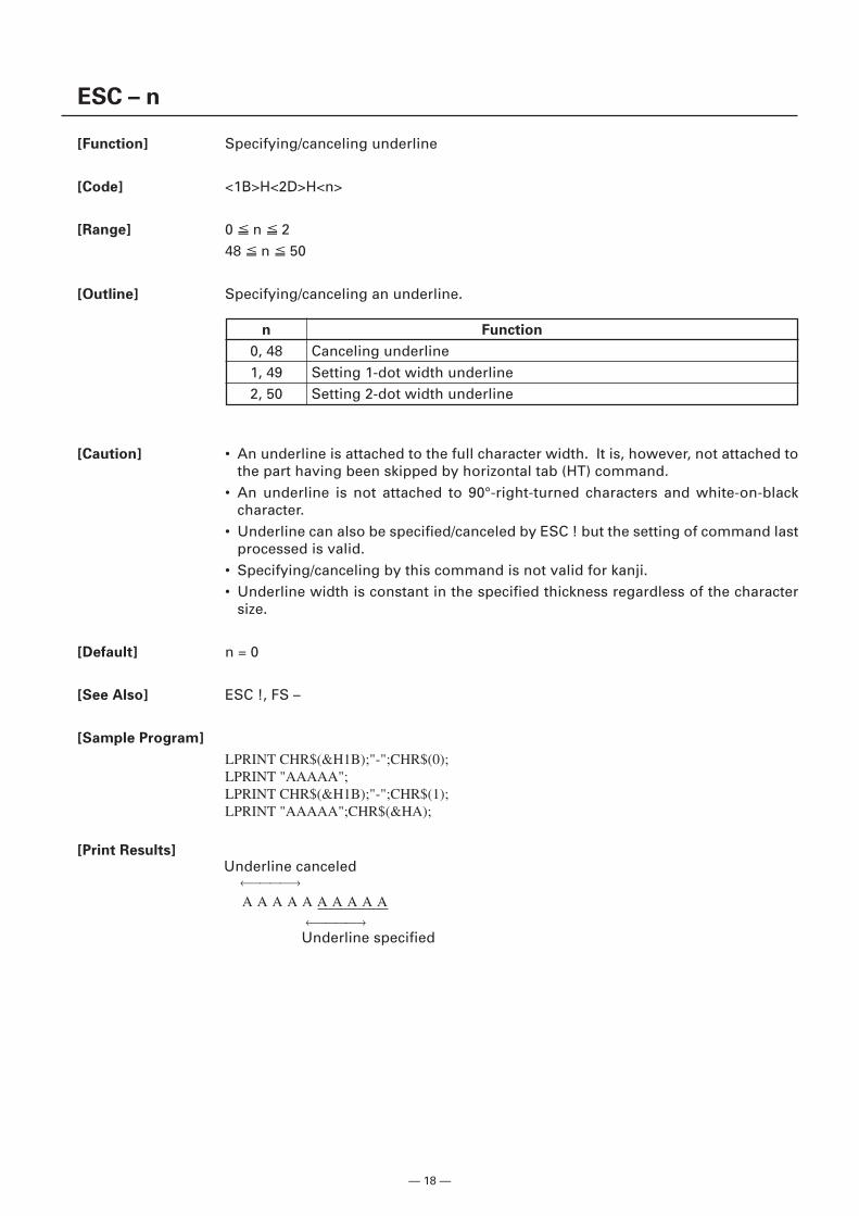
ESC – n
[Function] Specifying/canceling underline
[Code] <1B>H<2D>H<n>
[Range] 0 n 248 n 50
[Outline] Specifying/canceling an underline.
Underline canceled
Underline specified
←→
←→
A A A A A A A A A A
[Caution] • An underline is attached to the full character width. It is, however, not attached tothe part having been skipped by horizontal tab (HT) command.
• An underline is not attached to 90°-right-turned characters and white-on-blackcharacter.
• Underline can also be specified/canceled by ESC ! but the setting of command lastprocessed is valid.
• Specifying/canceling by this command is not valid for kanji.• Underline width is constant in the specified thickness regardless of the character
size.
[Default] n = 0
[See Also] ESC !, FS –
[Sample Program]
LPRINT CHR$(&H1B);"-";CHR$(0);LPRINT "AAAAA";LPRINT CHR$(&H1B);"-";CHR$(1);LPRINT "AAAAA";CHR$(&HA);
[Print Results]
n Function
0, 48 Canceling underline1, 49 Setting 1-dot width underline2, 50 Setting 2-dot width underline
— 19 —
ESC ? n
[Function] Deleting download characters
[Code] <1B>H<3F>H<n>
[Range] 32 n 126
[Outline] Deletes the downloaded characters of specified code.
[Caution] • The character “n” indicates the character code used to delete the defined pattern.After the deletion, characters are printed in the same pattern as the internalcharacters.
• This command deletes the code-defined pattern of the character font selected byESC !.
• This command is ignored if the specified character code is undefined.
[See Also] ESC &, ESC %
— 20 —
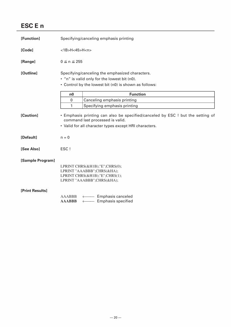
ESC E n
[Function] Specifying/canceling emphasis printing
[Code] <1B>H<45>H<n>
[Range] 0 n 255
[Outline] Specifying/canceling the emphasized characters.• “n” is valid only for the lowest bit (n0).• Control by the lowest bit (n0) is shown as follows:
[Caution] • Emphasis printing can also be specified/canceled by ESC ! but the setting ofcommand last processed is valid.
• Valid for all character types except HRI characters.
[Default] n = 0
[See Also] ESC !
[Sample Program]
LPRINT CHR$(&H1B);"E";CHR$(0);LPRINT "AAABBB";CHR$(&HA);LPRINT CHR$(&H1B);"E";CHR$(1);LPRINT "AAABBB";CHR$(&HA);
[Print Results]
AAABBB ← Emphasis canceledAAABBB ← Emphasis specified
n0 Function
0 Canceling emphasis printing1 Specifying emphasis printing
— 21 —
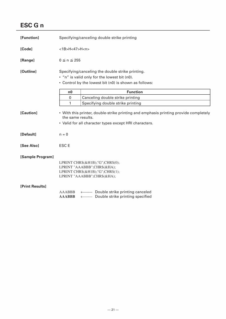
ESC G n
[Function] Specifying/canceling double strike printing
[Code] <1B>H<47>H<n>
[Range] 0 n 255
[Outline] Specifying/canceling the double strike printing.• “n” is valid only for the lowest bit (n0).• Control by the lowest bit (n0) is shown as follows:
n0 Function
0 Canceling double strike printing1 Specifying double strike printing
[Caution] • With this printer, double-strike printing and emphasis printing provide completelythe same results.
• Valid for all character types except HRI characters.
[Default] n = 0
[See Also] ESC E
[Sample Program]
LPRINT CHR$(&H1B);"G";CHR$(0);LPRINT "AAABBB";CHR$(&HA);LPRINT CHR$(&H1B);"G";CHR$(1);LPRINT "AAABBB";CHR$(&HA);
[Print Results]
AAABBB ← Double strike printing canceledAAABBB ← Double strike printing specified
— 22 —
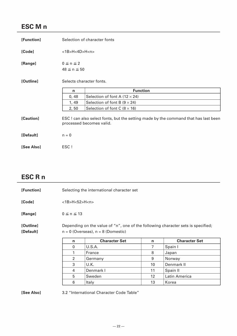
ESC M n
[Function] Selection of character fonts
[Code] <1B>H<4D>H<n>
[Range] 0 n 248 n 50
[Outline] Selects character fonts.
[Caution] ESC ! can also select fonts, but the setting made by the command that has last beenprocessed becomes valid.
[Default] n = 0
[See Also] ESC !
ESC R n
[Function] Selecting the international character set
[Code] <1B>H<52>H<n>
[Range] 0 n 13
[Outline] Depending on the value of “n”, one of the following character sets is specified;[Default] n = 0 (Overseas), n = 8 (Domestic)
n Function
0, 48 Selection of font A (12 × 24)1, 49 Selection of font B (9 × 24)2, 50 Selection of font C (8 × 16)
[See Also] 3.2 “International Character Code Table”
n Character Set n Character Set
0 U.S.A. 7 Spain I1 France 8 Japan2 Germany 9 Norway3 U.K. 10 Denmark II4 Denmark I 11 Spain II5 Sweden 12 Latin America6 Italy 13 Korea
— 23 —
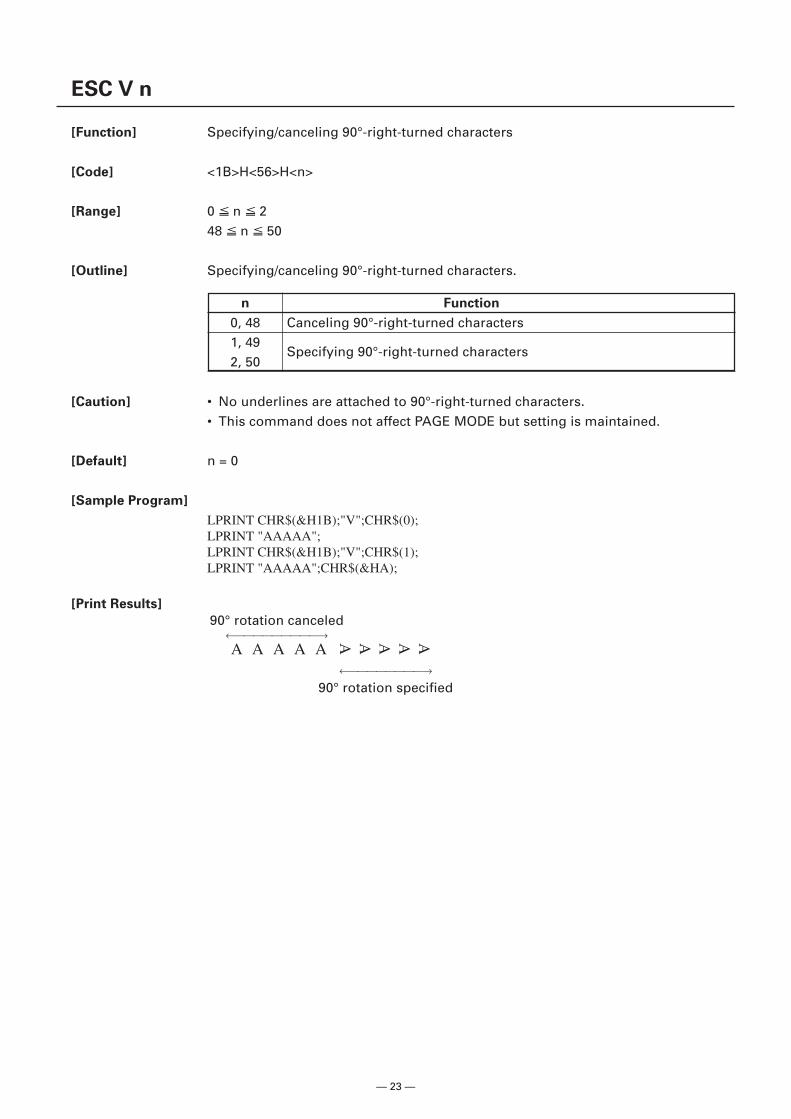
ESC V n
[Function] Specifying/canceling 90°-right-turned characters
[Code] <1B>H<56>H<n>
[Range] 0 n 248 n 50
[Outline] Specifying/canceling 90°-right-turned characters.
[Caution] • No underlines are attached to 90°-right-turned characters.• This command does not affect PAGE MODE but setting is maintained.
[Default] n = 0
[Sample Program]
LPRINT CHR$(&H1B);"V";CHR$(0);LPRINT "AAAAA";LPRINT CHR$(&H1B);"V";CHR$(1);LPRINT "AAAAA";CHR$(&HA);
[Print Results]
n Function
0, 48 Canceling 90°-right-turned characters1, 49
Specifying 90°-right-turned characters2, 50
90° rotation canceled←→
←→
90° rotation specified
AAAAA
A A A A A
— 24 —
ESC t n
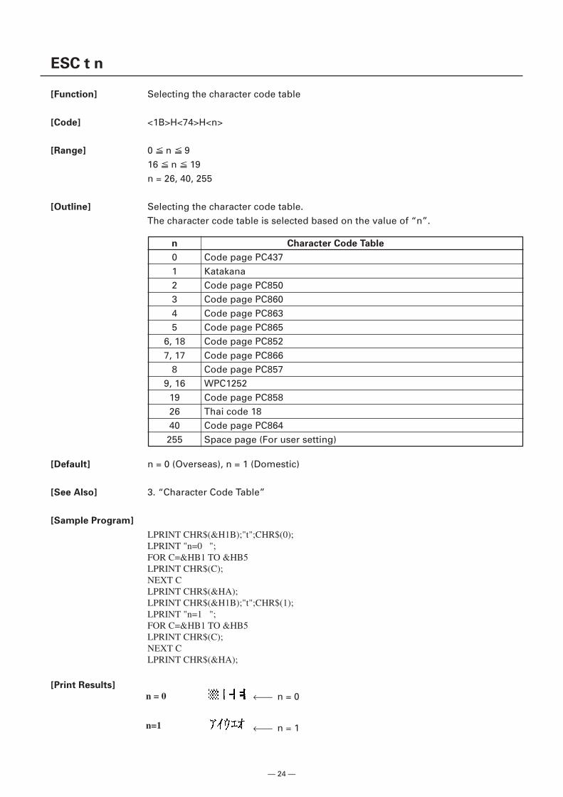
[Function] Selecting the character code table
[Code] <1B>H<74>H<n>
[Range] 0 n 916 n 19n = 26, 40, 255
[Outline] Selecting the character code table.The character code table is selected based on the value of “n”.
[Default] n = 0 (Overseas), n = 1 (Domestic)
[See Also] 3. “Character Code Table”
[Sample Program]
LPRINT CHR$(&H1B);"t";CHR$(0);LPRINT "n=0 ";FOR C=&HB1 TO &HB5LPRINT CHR$(C);NEXT CLPRINT CHR$(&HA);LPRINT CHR$(&H1B);"t";CHR$(1);LPRINT "n=1 ";FOR C=&HB1 TO &HB5LPRINT CHR$(C);NEXT CLPRINT CHR$(&HA);
[Print Results]
n Character Code Table
0 Code page PC4371 Katakana2 Code page PC8503 Code page PC8604 Code page PC8635 Code page PC865
6, 18 Code page PC8527, 17 Code page PC866
8 Code page PC8579, 16 WPC1252
19 Code page PC85826 Thai code 1840 Code page PC864255 Space page (For user setting)
← n = 0
← n = 1
n = 0
n=1
— 25 —
ESC { n
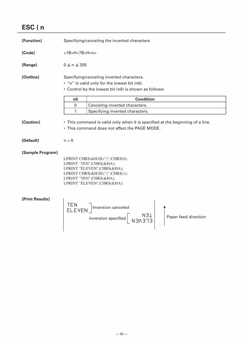
[Function] Specifying/canceling the inverted characters
[Code] <1B>H<7B>H<n>
[Range] 0 n 255
[Outline] Specifying/canceling inverted characters.• “n” is valid only for the lowest bit (n0).• Control by the lowest bit (n0) is shown as follows:
[Caution] • This command is valid only when it is specified at the beginning of a line.• This command does not affect the PAGE MODE.
[Default] n = 0
[Sample Program]
LPRINT CHR$(&H1B);"{";CHR$(0);LPRINT "TEN";CHR$(&HA);LPRINT "ELEVEN";CHR$(&HA);LPRINT CHR$(&H1B);"{";CHR$(1);LPRINT "TEN";CHR$(&HA);LPRINT "ELEVEN";CHR$(&HA);
[Print Results]
n0 Condition
0 Canceling inverted characters.1 Specifying inverted characters.
Paper feed direction
Inversion canceled
Inversion specified
— 26 —
Bit FunctionValue
Hex. Number Decimal Number
01234567
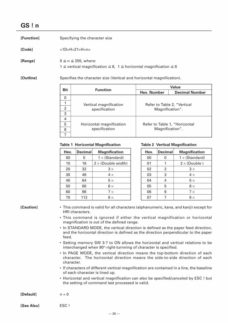
GS ! n
[Function] Specifying the character size
[Code] <1D>H<21>H<n>
[Range] 0 n 255, where:1 vertical magnification 8, 1 horizontal magnification 8
[Outline] Specifies the character size (Vertical and horizontal magnification).
Table 1 Horizontal Magnification
Hex. Decimal Magnification
00 0 1 × (Standard)10 16 2 × (Double width)20 32 3 ×30 48 4 ×40 64 5 ×50 80 6 ×60 96 7 ×70 112 8 ×
Vertical magnificationspecification
Refer to Table 2, “VerticalMagnification”.
Horizontal magnificationspecification
Refer to Table 1, “HorizontalMagnification”.
Table 2 Vertical Magnification
Hex. Decimal Magnification
00 0 1 × (Standard)01 1 2 × (Double )02 2 3 ×03 3 4 ×04 4 5 ×05 5 6 ×06 6 7 ×07 7 8 ×
[Caution] • This command is valid for all characters (alphanumeric, kana, and kanji) except forHRI characters.
• This command is ignored if either the vertical magnification or horizontalmagnification is out of the defined range.
• In STANDARD MODE, the vertical direction is defined as the paper feed direction,and the horizontal direction is defined as the direction perpendicular to the paperfeed.
• Setting memory SW 3-7 to ON allows the horizontal and vertical relations to beinterchanged when 90°-right-turnning of character is specified.
• In PAGE MODE, the vertical direction means the top-bottom direction of eachcharacter. The horizontal direction means the side-to-side direction of eachcharacter.
• If characters of different vertical magnification are contained in a line, the baselineof each character is lined up.
• Horizontal and vertical magnification can also be specified/canceled by ESC ! butthe setting of command last processed is valid.
[Default] n = 0
[See Also] ESC !
— 27 —
GS B n
[Function] Specifying/canceling the black/white inverted printing
[Code] <1D>H<42>H<n>
[Range] 0 n 255
[Outline] This command specifies or cancels the black/white inverted printing.• “n” is valid only for the lowest bit (n0).• Control by the lowest bit (n0) is shown as follows:
n0 Function
0 The black/white inverted printing is canceled.1 The black/white inverted printing is specified.
[Caution] • The black/white inversion works on internal and downloaded characters.• The black/white inversion works also on the right spacing of characters defined by
ESC SP.• This command does not affect the bit image, downloaded bit image, bar code, HRI
characters, or the skip area specified by HT, ESC $, or ESC \.• This command does not affect the space between lines.• Black/white inversion specification takes precedence over underline specification.
Underline printing specified is, therefore, nullified if black/white inversion isspecified; the underline setting, however, remains unchanged.
[Default] n = 0
— 28 —
GS b n
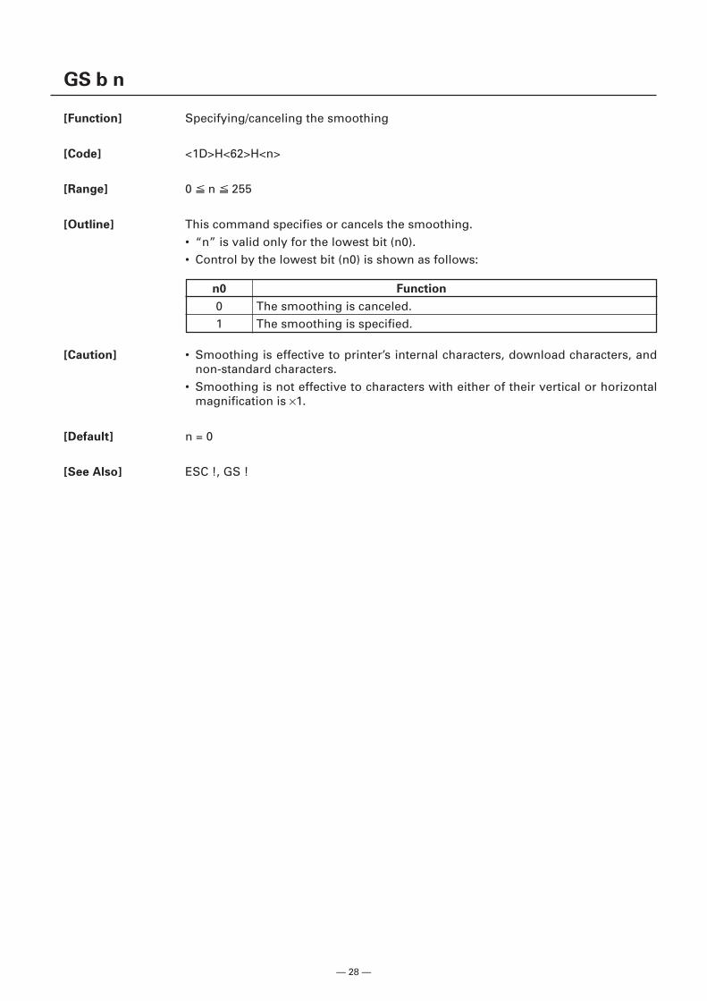
[Function] Specifying/canceling the smoothing
[Code] <1D>H<62>H<n>
[Range] 0 n 255
[Outline] This command specifies or cancels the smoothing.• “n” is valid only for the lowest bit (n0).• Control by the lowest bit (n0) is shown as follows:
[Caution] • Smoothing is effective to printer’s internal characters, download characters, andnon-standard characters.
• Smoothing is not effective to characters with either of their vertical or horizontalmagnification is ×1.
[Default] n = 0
[See Also] ESC !, GS !
n0 Function
0 The smoothing is canceled.1 The smoothing is specified.
— 29 —
2.2.3 Print Position Commands
HT
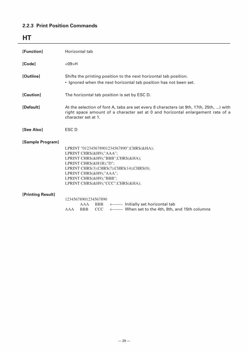
[Function] Horizontal tab
[Code] <09>H
[Outline] Shifts the printing position to the next horizontal tab position.• Ignored when the next horizontal tab position has not been set.
[Caution] The horizontal tab position is set by ESC D.
[Default] At the selection of font A, tabs are set every 8 characters (at 9th, 17th, 25th, ...) withright space amount of a character set at 0 and horizontal enlargement rate of acharacter set at 1.
[See Also] ESC D
[Sample Program]
LPRINT "012345678901234567890";CHR$(&HA);LPRINT CHR$(&H9);"AAA";LPRINT CHR$(&H9);"BBB";CHR$(&HA);LPRINT CHR$(&H1B);"D";LPRINT CHR$(3);CHR$(7);CHR$(14);CHR$(0);LPRINT CHR$(&H9);"AAA";LPRINT CHR$(&H9);"BBB";LPRINT CHR$(&H9);"CCC";CHR$(&HA);
[Printing Result]12345678901234567890
AAA BBB ← Initially set horizontal tabAAA BBB CCC ← When set to the 4th, 8th, and 15th columns
— 30 —
ESC $ n1 n2
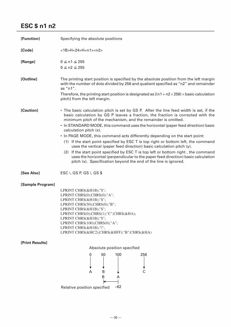
[Function] Specifying the absolute positions
[Code] <1B>H<24>H<n1><n2>
[Range] 0 n1 2550 n2 255
[Outline] The printing start position is specified by the absolute position from the left marginwith the number of dots divided by 256 and quatient specified as “n2” and remainderas “n1”.Therefore, the printing start position is designated as [(n1 + n2 × 256) × basic calculationpitch] from the left margin.
[Caution] • The basic calculation pitch is set by GS P. After the line feed width is set, if thebasic calculation by GS P leaves a fraction, the fraction is corrected with theminimum pitch of the mechanism, and the remainder is omitted.
• In STANDARD MODE, this command uses the horizontal (paper feed direction) basiccalculation pitch (x).
• In PAGE MODE, this command acts differently depending on the start point:(1) If the start point specified by ESC T is top right or bottom left, the command
uses the vertical (paper feed direction) basic calculation pitch (y).(2) If the start point specified by ESC T is top left or bottom right , the command
uses the horizontal (perpendicular to the paper feed direction) basic calculationpitch (x). Specification beyond the end of the line is ignored.
[See Also] ESC \, GS P, GS \, GS $
[Sample Program]
LPRINT CHR$(&H1B);"$";LPRINT CHR$(0);CHR$(0);"A";LPRINT CHR$(&H1B);"$";LPRINT CHR$(50);CHR$(0);"B";LPRINT CHR$(&H1B);"$";LPRINT CHR$(0);CHR$(1);"C";CHR$(&HA);LPRINT CHR$(&H1B);"$";LPRINT CHR$(100);CHR$(0);"A";LPRINT CHR$(&H1B);"\";LPRINT CHR$(&HC2);CHR$(&HFF);"B";CHR$(&HA)
[Print Results]
Relative position specified
Absolute position specified
0 50
A B
100
B A
–62
256
C
— 31 —
ESC D [n]k NULL
[Function] Setting horizontal tab position
[Code] <1B>H<44>H[<n>]k<00>H
[Range] 1 n 2550 k 32
[Outline] Specifying a horizontal tab position.• “n” indicates the number of columns from the beginning to the horizontal tab
position. Note, however, that “n = set position – 1”. For example, to set the positionat 9th column, n = 8 is to be specified.
• “k” denotes the number of horizontal tab positions you want to set. The tab positionis set at a position where it is “character width × n” from the beginning of a line.The character width, at this time, includes the space on the right. In double widthcharacters, it is made double the ordinary case. Tab positions that can be specifiedare maximum 32. Specifying tab positions exceeding this limit is ignored. <n>k,which denotes a setting position, is input in the increasing order and ends at <00>H.
• ESC D <NULL> clears all the set tab positions. Following clearing, the horizontaltab (HT) command is ignored.
[Caution] • When the data, <n>k, is equal to or smaller than its preceding data, <n>k–1, it isassumed that tab setting is finished. If this is the case, the next data onward will beprocessed as normal data.
• When the data, <n>k, exceeds a 1-line print area, set the horizontal tab position, as“Set column position = Maximum print columns + 1”.
• The horizontal tab position does not change even if the character width is alteredafter setting the horizontal tab position.
[Default] At the selection of font A, tabs are set every 8 characters (at 9th, 17th, 25th, ...) withright space amount of a character set at 0 and horizontal enlargement rate of acharacter set at 1.
[See Also] HT
[Sample Program] Refer to Sample Program and Print Results for HT.
— 32 —
ESC T n
[Function] Selecting the character printing direction in PAGE MODE
[Code] <1B>H<54>H<n>
[Range] 0 n 348 n 51
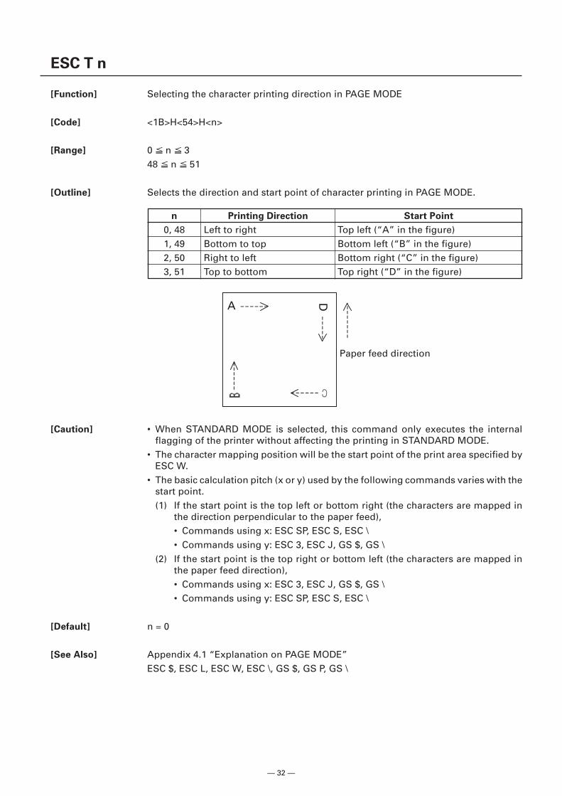
[Outline] Selects the direction and start point of character printing in PAGE MODE.
[Caution] • When STANDARD MODE is selected, this command only executes the internalflagging of the printer without affecting the printing in STANDARD MODE.
• The character mapping position will be the start point of the print area specified byESC W.
• The basic calculation pitch (x or y) used by the following commands varies with thestart point.(1) If the start point is the top left or bottom right (the characters are mapped in
the direction perpendicular to the paper feed),• Commands using x: ESC SP, ESC S, ESC \• Commands using y: ESC 3, ESC J, GS $, GS \
(2) If the start point is the top right or bottom left (the characters are mapped inthe paper feed direction),• Commands using x: ESC 3, ESC J, GS $, GS \• Commands using y: ESC SP, ESC S, ESC \
[Default] n = 0
[See Also] Appendix 4.1 “Explanation on PAGE MODE”ESC $, ESC L, ESC W, ESC \, GS $, GS P, GS \
n Printing Direction Start Point
0, 48 Left to right Top left (“A” in the figure)1, 49 Bottom to top Bottom left (“B” in the figure)2, 50 Right to left Bottom right (“C” in the figure)3, 51 Top to bottom Top right (“D” in the figure)
A D
Paper feed direction
— 33 —
ESC W xL xH yL yH dxL dxH dyL dyH
[Function] Defining the print area in PAGE MODE
[Code] <1B>H<57>H<xL><xH><yL><yH><dxL><dxH><dyL><dyH>
[Range] 0 xL, xH, yL, yH, dxL, dxH, dyL, dyH 255except for dxL = dxH = 0 or dyL = dyH = 0
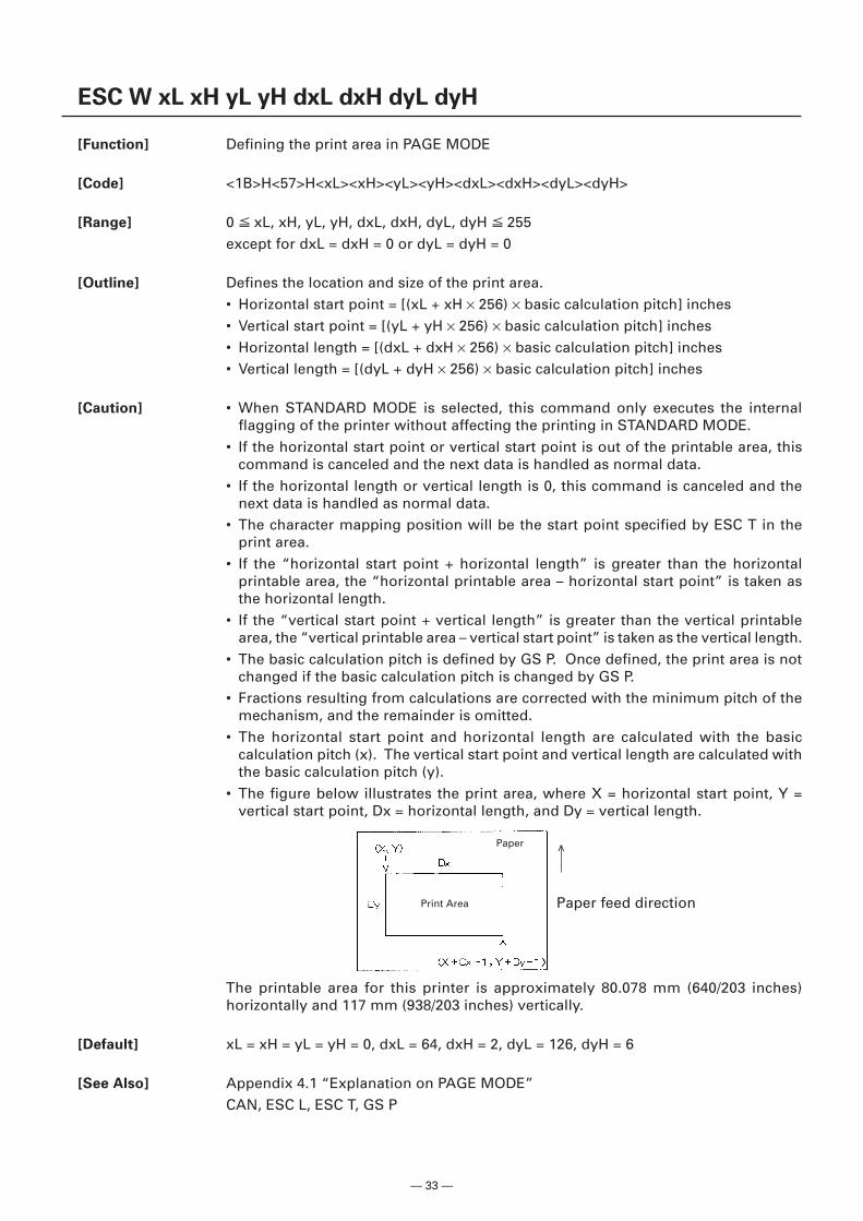
[Outline] Defines the location and size of the print area.• Horizontal start point = [(xL + xH × 256) × basic calculation pitch] inches• Vertical start point = [(yL + yH × 256) × basic calculation pitch] inches• Horizontal length = [(dxL + dxH × 256) × basic calculation pitch] inches• Vertical length = [(dyL + dyH × 256) × basic calculation pitch] inches
[Caution] • When STANDARD MODE is selected, this command only executes the internalflagging of the printer without affecting the printing in STANDARD MODE.
• If the horizontal start point or vertical start point is out of the printable area, thiscommand is canceled and the next data is handled as normal data.
• If the horizontal length or vertical length is 0, this command is canceled and thenext data is handled as normal data.
• The character mapping position will be the start point specified by ESC T in theprint area.
• If the “horizontal start point + horizontal length” is greater than the horizontalprintable area, the “horizontal printable area – horizontal start point” is taken asthe horizontal length.
• If the “vertical start point + vertical length” is greater than the vertical printablearea, the “vertical printable area – vertical start point” is taken as the vertical length.
• The basic calculation pitch is defined by GS P. Once defined, the print area is notchanged if the basic calculation pitch is changed by GS P.
• Fractions resulting from calculations are corrected with the minimum pitch of themechanism, and the remainder is omitted.
• The horizontal start point and horizontal length are calculated with the basiccalculation pitch (x). The vertical start point and vertical length are calculated withthe basic calculation pitch (y).
• The figure below illustrates the print area, where X = horizontal start point, Y =vertical start point, Dx = horizontal length, and Dy = vertical length.
The printable area for this printer is approximately 80.078 mm (640/203 inches)horizontally and 117 mm (938/203 inches) vertically.
[Default] xL = xH = yL = yH = 0, dxL = 64, dxH = 2, dyL = 126, dyH = 6
[See Also] Appendix 4.1 “Explanation on PAGE MODE”CAN, ESC L, ESC T, GS P
Print Area
Paper
Paper feed direction
<
— 34 —
ESC \ nL nH
[Function] Specifying the relative position
[Code] <1B>H<5C>H<nL><nH>
[Range] 0 nL 2550 nH 255
[Outline] This command specifies the next print start position in a relative position with respectto the current position. The next print start position will be at a point of [(nL + nH ×256) × basic calculation pitch] inches away from the current position.
[Caution] • Specification of a position outside the print area is ignored.• If a new position is specified to the right of the current position in the direction of
printing, it should be specified as positive (+). If it is to the left, it should be asnegative (–).
• A negative value is the complement of 65536. For example, to move the positionby N pitches to the left, specify it as:nL + nH × 256 = 65536 – N
• The basic calculation pitch is set by GS P.• Fractions resulting from calculation are corrected with the minimum pitch of the
mechanism, and the remainder is omitted.• In STANDARD MODE, this command uses the horizontal basic calculation pitch (x).• In PAGE MODE, this command acts differently depending on the start point:
(1) If the start point specified by ESC T is top left or bottom right, the commandspecifies the relative position in the direction perpendicular to the paper feed(the character’s side-to-side direction), using the horizontal basic calculationpitch (x).
(2) If the start point is top right or bottom left, the command specifies the relativeposition in the paper feed direction (the character’s side-to-side direction), usingthe vertical basic calculation pitch (y).
[See Also] ESC $, GS P
[Sample Program] Refer to Sample Program and Print Results for ESC $.
— 35 —
ESC a n
[Function] Aligning the characters
[Code] <1B>H<61>H<n>
[Range] 0 n 248 n 50
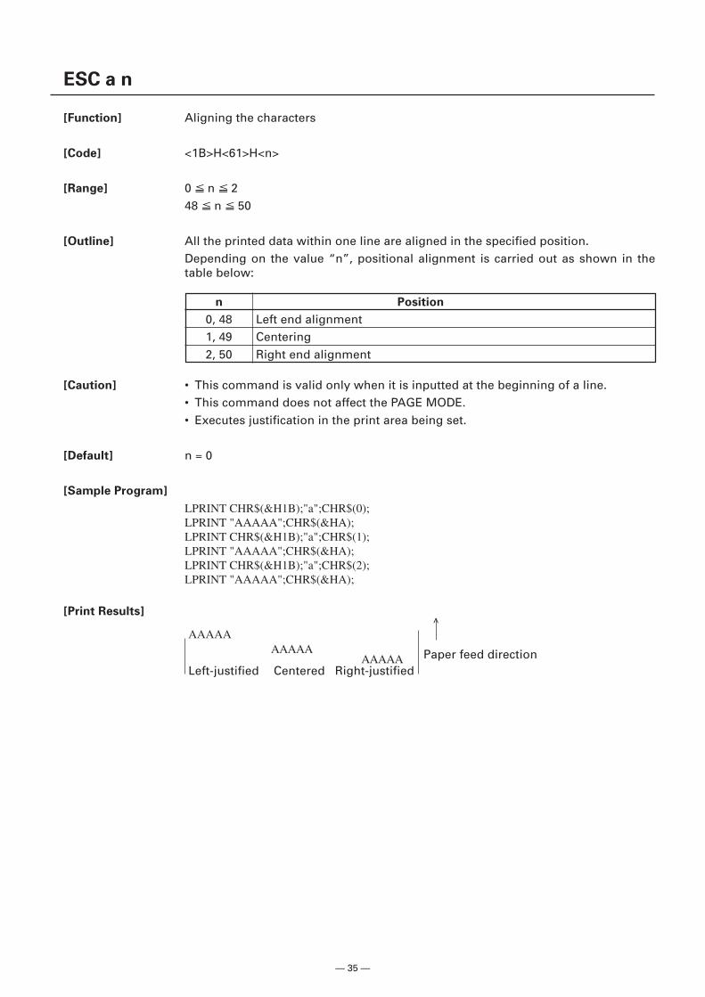
[Outline] All the printed data within one line are aligned in the specified position.Depending on the value “n”, positional alignment is carried out as shown in thetable below:
[Caution] • This command is valid only when it is inputted at the beginning of a line.• This command does not affect the PAGE MODE.• Executes justification in the print area being set.
[Default] n = 0
[Sample Program]
LPRINT CHR$(&H1B);"a";CHR$(0);LPRINT "AAAAA";CHR$(&HA);LPRINT CHR$(&H1B);"a";CHR$(1);LPRINT "AAAAA";CHR$(&HA);LPRINT CHR$(&H1B);"a";CHR$(2);LPRINT "AAAAA";CHR$(&HA);
[Print Results]
n Position
0, 48 Left end alignment1, 49 Centering2, 50 Right end alignment
Paper feed directionLeft-justified Centered Right-justified
AAAAAAAAAA
AAAAA
<
— 36 —
GS $ nL nH
[Function] Specifying the absolute vertical position of characters in PAGE MODE
[Code] <1D>H<24>H<nL><nH>
[Range] 0 nL 2550 nH 255
[Outline] Specifies the vertical position of character at the start point of data development inPAGE MODE using absolute position based on the start position. The position ofvertical direction of character at the start position of next data development is theposition [(nL + nH × 256) × basic calculation pitch] from the start position.
[Caution] • This command is ignored except at PAGE MODE selection.• Absolute position setting exceeding the specified print area is ignored.• Position in horizontal direction of character at the start position of data development
is not shifted.• Start point used as the reference is set by ESC T.• The following operation occurs at the start point of ESC T.
(1) When start point is set at upper left or lower right, the absolute position ofpaper feed direction (vertical direction of character) is set. In this case, basiccalculation pitch (y) of vertical direction is used.
(2) When start point is set at upper right or lower left, the absolute position ofvertical direction of paper feed (vertical direction of character) is set. In thiscase, basic calculation pitch (x) of horizontal direction is used.
• Basic calculation pitch is set by GS P.• When fractional number is caused by the calculation, it is corrected by the minimum
pitch of mechanism and the rest is discarded.
[See Also] ESC $, ESC T, ESC W, ESC \, GS P, GS \
— 37 —
GS L nL nH
[Function] Setting the left margin
[Code] <1D>H<4C>H<nL><nH>
[Range] 0 nL 2550 nH 255
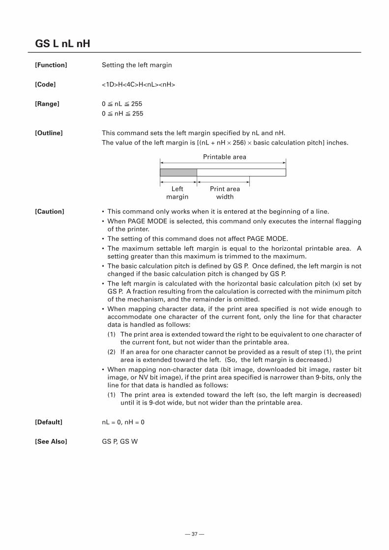
[Outline] This command sets the left margin specified by nL and nH.The value of the left margin is [(nL + nH × 256) × basic calculation pitch] inches.
[Caution] • This command only works when it is entered at the beginning of a line.• When PAGE MODE is selected, this command only executes the internal flagging
of the printer.• The setting of this command does not affect PAGE MODE.• The maximum settable left margin is equal to the horizontal printable area. A
setting greater than this maximum is trimmed to the maximum.• The basic calculation pitch is defined by GS P. Once defined, the left margin is not
changed if the basic calculation pitch is changed by GS P.• The left margin is calculated with the horizontal basic calculation pitch (x) set by
GS P. A fraction resulting from the calculation is corrected with the minimum pitchof the mechanism, and the remainder is omitted.
• When mapping character data, if the print area specified is not wide enough toaccommodate one character of the current font, only the line for that characterdata is handled as follows:(1) The print area is extended toward the right to be equivalent to one character of
the current font, but not wider than the printable area.(2) If an area for one character cannot be provided as a result of step (1), the print
area is extended toward the left. (So, the left margin is decreased.)• When mapping non-character data (bit image, downloaded bit image, raster bit
image, or NV bit image), if the print area specified is narrower than 9-bits, only theline for that data is handled as follows:(1) The print area is extended toward the left (so, the left margin is decreased)
until it is 9-dot wide, but not wider than the printable area.
[Default] nL = 0, nH = 0
[See Also] GS P, GS W
Printable area
Print areawidth
Leftmargin
— 38 —
GS T n
[Function] Moving print position to top of the line
[Code] <1D>H<54>H<n>
[Range] n = 0, 1, 48, 49
[Outline] Moves print position to top of the line.• “n” specifies data processing in print buffer at the execution of this command.
When printing is specified (n = 1, 49), data in the print buffer is printed and linefeeding in accordance with the specified line feed is executed.When erasing is specified (n = 0, 48), cancel processing of print data in the printbuffer is executed with other data and setting retained.
n Function
0, 48 Moves print position after erasing the data in print buffer.1, 49 Moves print position after printing the data in print buffer.
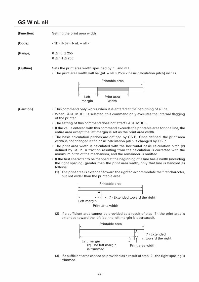
— 39 —
A
GS W nL nH
[Function] Setting the print area width
[Code] <1D>H<57>H<nL><nH>
[Range] 0 nL 2550 nH 255
[Outline] Sets the print area width specified by nL and nH.• The print area width will be [(nL + nH × 256) × basic calculation pitch] inches.
[Caution] • This command only works when it is entered at the beginning of a line.• When PAGE MODE is selected, this command only executes the internal flagging
of the printer.• The setting of this command does not affect PAGE MODE.• If the value entered with this command exceeds the printable area for one line, the
entire area except the left margin is set as the print area width.• The basic calculation pitches are defined by GS P. Once defined, the print area
width is not changed if the basic calculation pitch is changed by GS P.• The print area width is calculated with the horizontal basic calculation pitch (x)
defined by GS P. A fraction resulting from the calculation is corrected with theminimum pitch of the mechanism, and the remainder is omitted.
• If the first character to be mapped at the beginning of a line has a width (includingthe right spacing) greater than the print area width, only that line is handled asfollows:(1) The print area is extended toward the right to accommodate the first character,
but not wider than the printable area.
Print areawidth
Leftmargin
Printable area
Print area widthLeft margin
Printable area
(1) Extended toward the right
(1) Extendedtoward the right
Printable area
Left marginPrint area width
A
(2) The left marginis trimmed
(2) If a sufficient area cannot be provided as a result of step (1), the print area isextended toward the left (so, the left margin is decreased).
(3) If a sufficient area cannot be provided as a result of step (2), the right spacing istrimmed.
— 40 —
• When mapping a bit image (or downloaded bit image), if the print area is narrowerthan the minimum width of the bit image (two dots for single density, or one dotfor double density), only the line for that image is handled as follows:(1) The print area is extended toward the left (so, the left margin is decreased)
until it is equal to the minimum width of the image, but not wider than theprintable area.
[Default] nL = 64, nH = 2
[See Also] GS L, GS P
— 41 —
GS \ nL nH
[Function] Specifying the relative vertical position of a character in PAGE MODE
[Code] <1D>H<5C>H<nL><nH>
[Range] 0 nL 2550 nH 255
[Outline] This command is used in PAGE MODE to specify the vertical position of a characterin the data mapping start position, in a relative position with respect to the currentposition. The next data mapping start position will be at a point [(nL + nH × 256) ×basic calculation pitch] inches away from the current position.
[Caution] • This command is ignored when PAGE MODE is not selected.• If a new position is specified for a character located beneath the current position, it
should be specified as positive (+). If it is above the current position, it should benegative (–).
• A negative value is the complement of 65536. For example, to move the positionby N pitches up, specify it as:
nL + nH × 256 = 65536 – N• The specification of a relative position outside the specified print area is ignored.• Depending on the start point specified by ESC T, this command acts as follows:
(1) If the start point is the top left or bottom right, the command specifies therelative position in the paper feed direction (the character’s top-bottom direction)using the vertical basic calculation pitch (y).
(2) If the start point is the top right or bottom left, the command specifies therelative position in the direction perpendicular to the paper feed (the character’stop-bottom direction) using the horizontal basic calculation pitch (x).
• The basic calculation pitch is set by GS P.• Fractions resulting from calculations are corrected with the minimum pitch of the
mechanism, and the remainder is omitted.
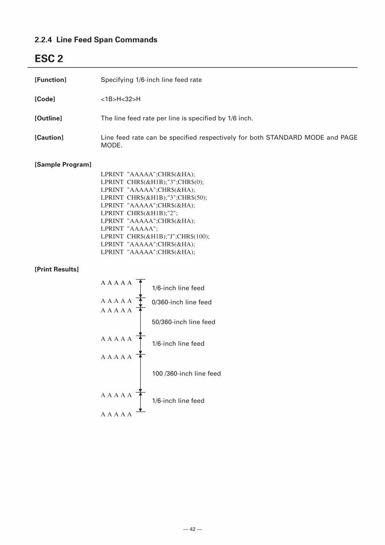
— 42 —
2.2.4 Line Feed Span Commands
ESC 2
[Function] Specifying 1/6-inch line feed rate
[Code] <1B>H<32>H
[Outline] The line feed rate per line is specified by 1/6 inch.
[Caution] Line feed rate can be specified respectively for both STANDARD MODE and PAGEMODE.
[Sample Program]
LPRINT "AAAAA";CHR$(&HA);LPRINT CHR$(&H1B);"3";CHR$(0);LPRINT "AAAAA";CHR$(&HA);LPRINT CHR$(&H1B);"3";CHR$(50);LPRINT "AAAAA";CHR$(&HA);LPRINT CHR$(&H1B);"2";LPRINT "AAAAA";CHR$(&HA);LPRINT "AAAAA";LPRINT CHR$(&H1B);"J";CHR$(100);LPRINT "AAAAA";CHR$(&HA);LPRINT "AAAAA";CHR$(&HA);
[Print Results]
1/6-inch line feed
0/360-inch line feed
50/360-inch line feed
1/6-inch line feed
100 /360-inch line feed
1/6-inch line feed
A A A A A
A A A A A
A A A A A
A A A A A
A A A A A
A A A A A
A A A A A
— 43 —
ESC 3 n
[Function] Setting line feed rate of minimum pitch
[Code] <1B>H<33>H<n>
[Range] 0 n 255
[Outline] Sets the line feed width per line to [n × basic calculation pitch] inches.
[Caution] • The line feed width can be set separately for the STANDARD and PAGE MODES.• The basic calculation pitch is set by GS P. Once defined, the line feed width is not
changed if the basic calculation pitch is changed by GS P.• Fractions resulting from calculation are corrected with the minimum pitch of the
mechanism, and the remainder is omitted.• In STANDARD MODE, this command uses the vertical (paper feed direction) basic
calculation pitch (y).• In PAGE MODE, this command acts differently depending on the start point:
(1) If the start point specified by ESC T is top left or bottom right, the commanduses the vertical (paper feed direction) basic calculation pitch (y).
(2) If the start point specified by ESC T is top right or bottom left, the commanduses the horizontal (perpendicular to the paper feed direction) basic calculationpitch (x).
• The maximum settable line feed width is 1016 mm (40 inches). A setting greaterthan this maximum is trimmed to the maximum.
[Default] When memory switch 3-7 is OFF: Line feed is approx. 4.23 mm.When memory switch 3-7 is ON: Line feed is approx. 3.75 mm.
[See Also] ESC 2, GS P
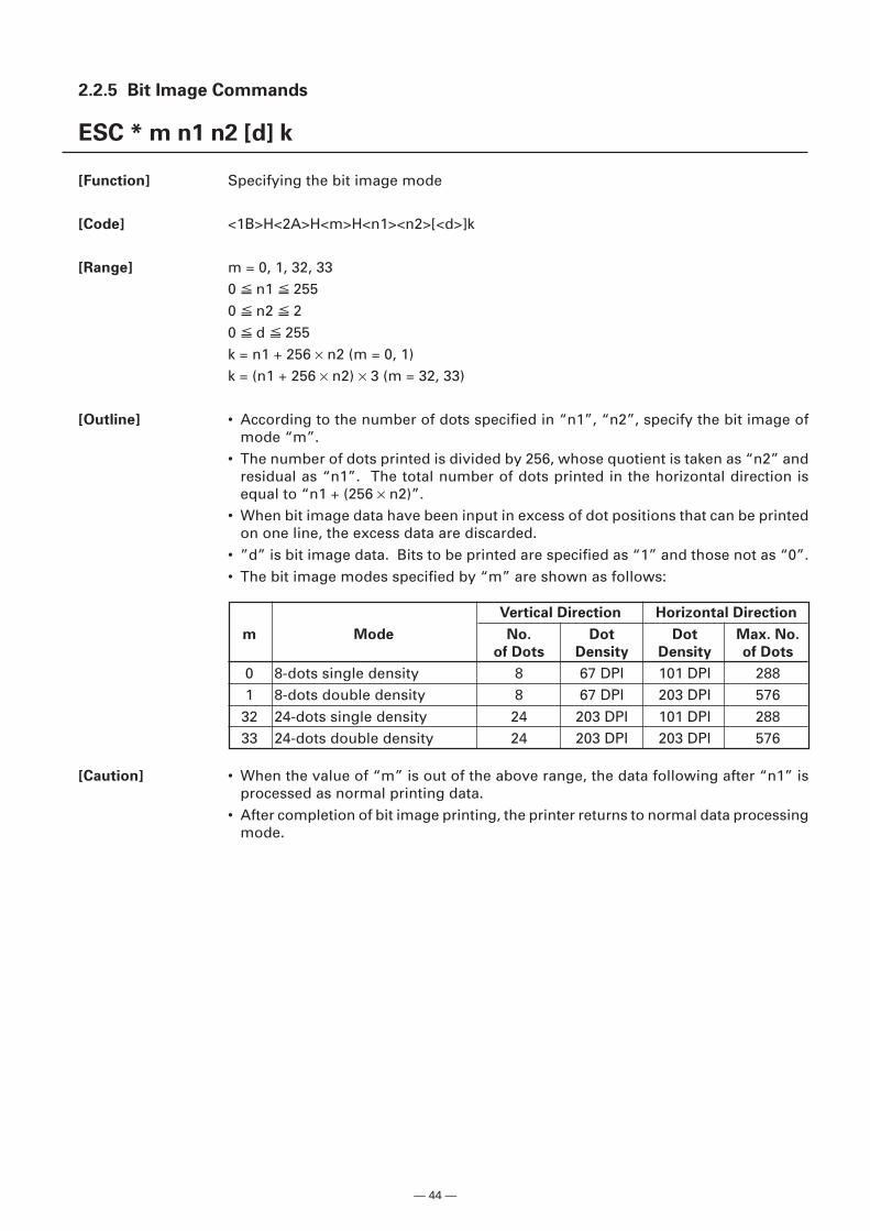
— 44 —
2.2.5 Bit Image Commands
ESC * m n1 n2 [d] k
[Function] Specifying the bit image mode
[Code] <1B>H<2A>H<m>H<n1><n2>[<d>]k
[Range] m = 0, 1, 32, 330 n1 2550 n2 20 d 255k = n1 + 256 × n2 (m = 0, 1)k = (n1 + 256 × n2) × 3 (m = 32, 33)
[Outline] • According to the number of dots specified in “n1”, “n2”, specify the bit image ofmode “m”.
• The number of dots printed is divided by 256, whose quotient is taken as “n2” andresidual as “n1”. The total number of dots printed in the horizontal direction isequal to “n1 + (256 × n2)”.
• When bit image data have been input in excess of dot positions that can be printedon one line, the excess data are discarded.
• ”d” is bit image data. Bits to be printed are specified as “1” and those not as “0”.• The bit image modes specified by “m” are shown as follows:
[Caution] • When the value of “m” is out of the above range, the data following after “n1” isprocessed as normal printing data.
• After completion of bit image printing, the printer returns to normal data processingmode.
Vertical Direction Horizontal Direction
m Mode No. Dot Dot Max. No.
of Dots Density Density of Dots
0 8-dots single density 8 67 DPI 101 DPI 2881 8-dots double density 8 67 DPI 203 DPI 57632 24-dots single density 24 203 DPI 101 DPI 28833 24-dots double density 24 203 DPI 203 DPI 576
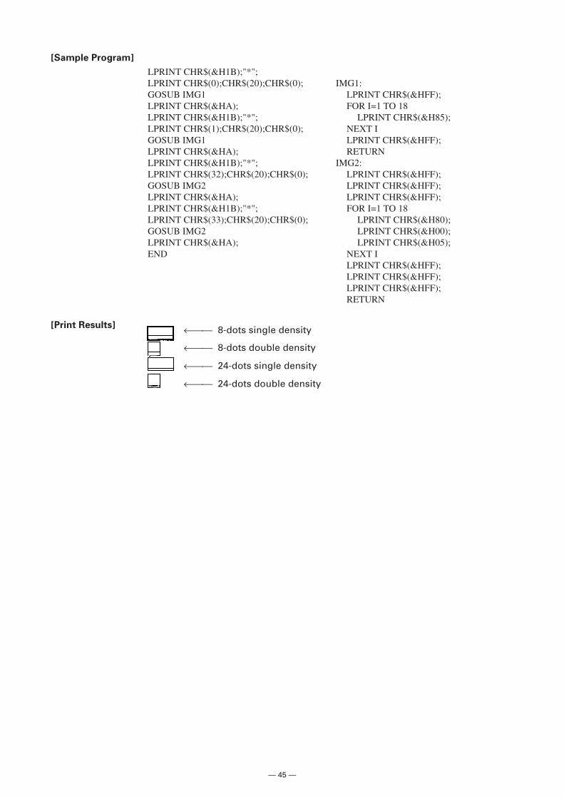
— 45 —
[Sample Program]
LPRINT CHR$(&H1B);"*";LPRINT CHR$(0);CHR$(20);CHR$(0); IMG1:GOSUB IMG1 LPRINT CHR$(&HFF);LPRINT CHR$(&HA); FOR I=1 TO 18LPRINT CHR$(&H1B);"*"; LPRINT CHR$(&H85);LPRINT CHR$(1);CHR$(20);CHR$(0); NEXT IGOSUB IMG1 LPRINT CHR$(&HFF);LPRINT CHR$(&HA); RETURNLPRINT CHR$(&H1B);"*"; IMG2:LPRINT CHR$(32);CHR$(20);CHR$(0); LPRINT CHR$(&HFF);GOSUB IMG2 LPRINT CHR$(&HFF);LPRINT CHR$(&HA); LPRINT CHR$(&HFF);LPRINT CHR$(&H1B);"*"; FOR I=1 TO 18LPRINT CHR$(33);CHR$(20);CHR$(0); LPRINT CHR$(&H80);GOSUB IMG2 LPRINT CHR$(&H00);LPRINT CHR$(&HA); LPRINT CHR$(&H05);END NEXT I
LPRINT CHR$(&HFF);LPRINT CHR$(&HFF);LPRINT CHR$(&HFF);RETURN
[Print Results] ← 8-dots single density
← 8-dots double density
← 24-dots single density
← 24-dots double density
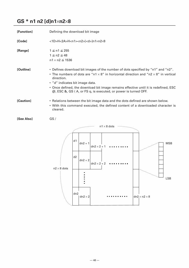
— 46 —
GS * n1 n2 [d]n1×n2×8
[Function] Defining the download bit image
[Code] <1D>H<2A>H<n1><n2>[<d>]n1×n2×8
[Range] 1 n1 2551 n2 48n1 × n2 1536
[Outline] • Defines download bit images of the number of dots specified by “n1” and “n2”.• The numbers of dots are “n1 × 8” in horizontal direction and “n2 × 8” in vertical
direction.• ”d” indicates bit image data.• Once defined, the download bit image remains effective until it is redefined, ESC
@, ESC &, GS ( A, or FS q, is executed, or power is turned OFF.
[Caution] • Relations between the bit image data and the dots defined are shown below.• With this command executed, the defined content of a downloaded character is
cleared.
[See Also] GS /
dn2 + 1
dn2 + 2
dn2 × 2
dn2 × 2 + 1
dn2 × 2 + 2
dn2 × n2 × 8
MSB
LSB
n1 × 8 dots
n2 × 8 dots
d1
d2
dn2
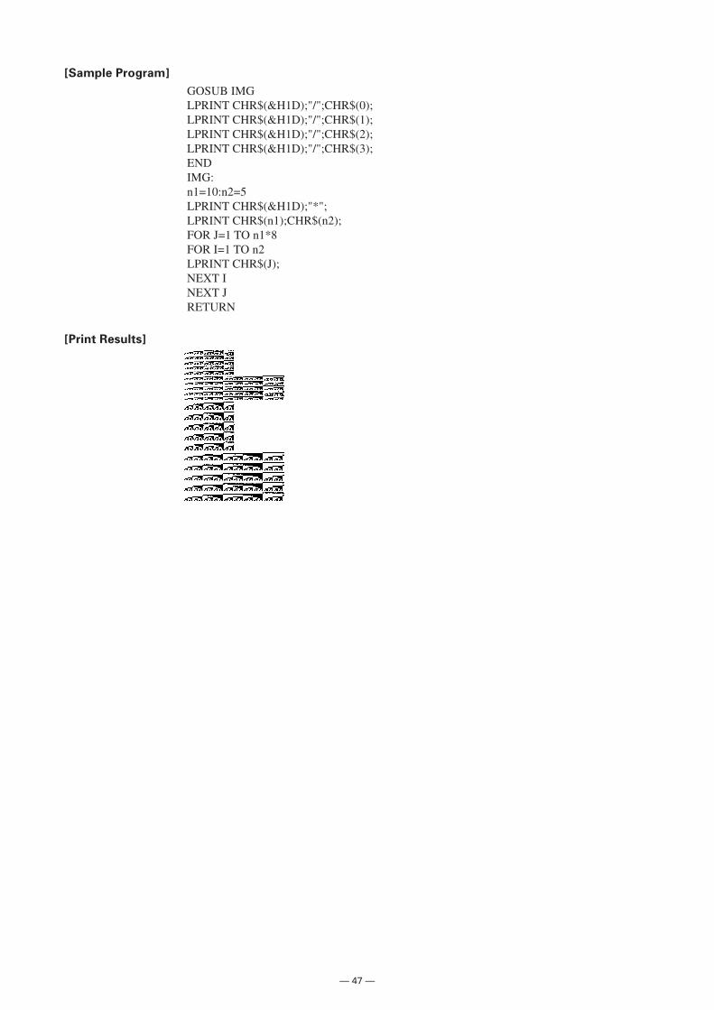
— 47 —
[Sample Program]
GOSUB IMGLPRINT CHR$(&H1D);"/";CHR$(0);LPRINT CHR$(&H1D);"/";CHR$(1);LPRINT CHR$(&H1D);"/";CHR$(2);LPRINT CHR$(&H1D);"/";CHR$(3);ENDIMG:n1=10:n2=5LPRINT CHR$(&H1D);"*";LPRINT CHR$(n1);CHR$(n2);FOR J=1 TO n1*8FOR I=1 TO n2LPRINT CHR$(J);NEXT INEXT JRETURN
[Print Results]
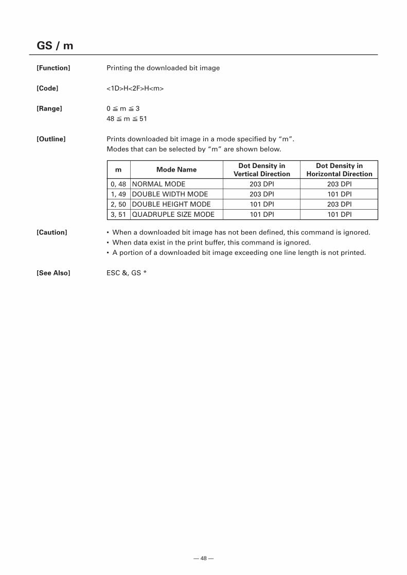
— 48 —
GS / m
[Function] Printing the downloaded bit image
[Code] <1D>H<2F>H<m>
[Range] 0 m 348 m 51
[Outline] Prints downloaded bit image in a mode specified by “m”.Modes that can be selected by “m” are shown below.
[Caution] • When a downloaded bit image has not been defined, this command is ignored.• When data exist in the print buffer, this command is ignored.• A portion of a downloaded bit image exceeding one line length is not printed.
[See Also] ESC &, GS *
m Mode NameDot Density in Dot Density in
Vertical Direction Horizontal Direction
0, 48 NORMAL MODE 203 DPI 203 DPI1, 49 DOUBLE WIDTH MODE 203 DPI 101 DPI2, 50 DOUBLE HEIGHT MODE 101 DPI 203 DPI3, 51 QUADRUPLE SIZE MODE 101 DPI 101 DPI
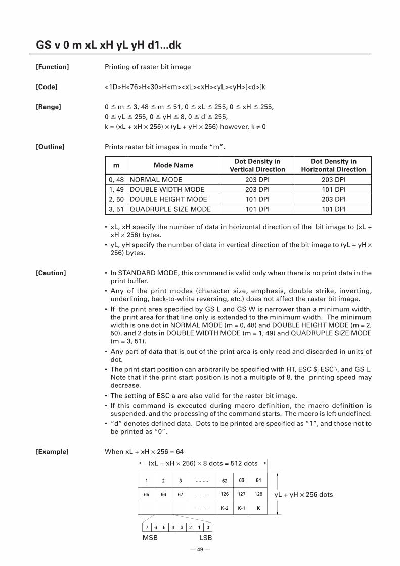
— 49 —
GS v 0 m xL xH yL yH d1...dk
[Function] Printing of raster bit image
[Code] <1D>H<76>H<30>H<m><xL><xH><yL><yH>[<d>]k
[Range] 0 m 3, 48 m 51, 0 xL 255, 0 xH 255,0 yL 255, 0 yH 8, 0 d 255,k = (xL + xH × 256) × (yL + yH × 256) however, k ≠ 0
[Outline] Prints raster bit images in mode “m”.
• xL, xH specify the number of data in horizontal direction of the bit image to (xL +xH × 256) bytes.
• yL, yH specify the number of data in vertical direction of the bit image to (yL + yH ×256) bytes.
[Caution] • In STANDARD MODE, this command is valid only when there is no print data in theprint buffer.
• Any of the print modes (character size, emphasis, double strike, inverting,underlining, back-to-white reversing, etc.) does not affect the raster bit image.
• If the print area specified by GS L and GS W is narrower than a minimum width,the print area for that line only is extended to the minimum width. The minimumwidth is one dot in NORMAL MODE (m = 0, 48) and DOUBLE HEIGHT MODE (m = 2,50), and 2 dots in DOUBLE WIDTH MODE (m = 1, 49) and QUADRUPLE SIZE MODE(m = 3, 51).
• Any part of data that is out of the print area is only read and discarded in units ofdot.
• The print start position can arbitrarily be specified with HT, ESC $, ESC \, and GS L.Note that if the print start position is not a multiple of 8, the printing speed maydecrease.
• The setting of ESC a are also valid for the raster bit image.• If this command is executed during macro definition, the macro definition is
suspended, and the processing of the command starts. The macro is left undefined.• “d” denotes defined data. Dots to be printed are specified as “1”, and those not to
be printed as “0”.
[Example] When xL + xH × 256 = 64
m Mode NameDot Density in Dot Density in
Vertical Direction Horizontal Direction
0, 48 NORMAL MODE 203 DPI 203 DPI1, 49 DOUBLE WIDTH MODE 203 DPI 101 DPI2, 50 DOUBLE HEIGHT MODE 101 DPI 203 DPI3, 51 QUADRUPLE SIZE MODE 101 DPI 101 DPI
7
1 2 3 62
126
K-2
127
K-1
128
K
63 64
65 66 67
6 5 4 3 2 1 0
LSBMSB
yL + yH × 256 dots
(xL + xH × 256) × 8 dots = 512 dots
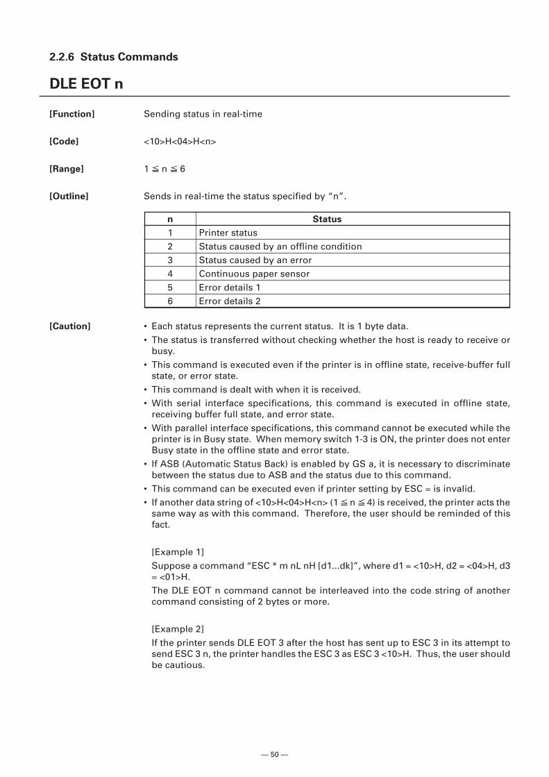
— 50 —
2.2.6 Status Commands
DLE EOT n
[Function] Sending status in real-time
[Code] <10>H<04>H<n>
[Range] 1 n 6
[Outline] Sends in real-time the status specified by “n”.
[Caution] • Each status represents the current status. It is 1 byte data.• The status is transferred without checking whether the host is ready to receive or
busy.• This command is executed even if the printer is in offline state, receive-buffer full
state, or error state.• This command is dealt with when it is received.• With serial interface specifications, this command is executed in offline state,
receiving buffer full state, and error state.• With parallel interface specifications, this command cannot be executed while the
printer is in Busy state. When memory switch 1-3 is ON, the printer does not enterBusy state in the offline state and error state.
• If ASB (Automatic Status Back) is enabled by GS a, it is necessary to discriminatebetween the status due to ASB and the status due to this command.
• This command can be executed even if printer setting by ESC = is invalid.• If another data string of <10>H<04>H<n> (1 n 4) is received, the printer acts the
same way as with this command. Therefore, the user should be reminded of thisfact.
[Example 1]Suppose a command “ESC * m nL nH [d1...dk]”, where d1 = <10>H, d2 = <04>H, d3= <01>H.The DLE EOT n command cannot be interleaved into the code string of anothercommand consisting of 2 bytes or more.
[Example 2]If the printer sends DLE EOT 3 after the host has sent up to ESC 3 in its attempt tosend ESC 3 n, the printer handles the ESC 3 as ESC 3 <10>H. Thus, the user shouldbe cautious.
n Status
1 Printer status2 Status caused by an offline condition3 Status caused by an error4 Continuous paper sensor5 Error details 16 Error details 2
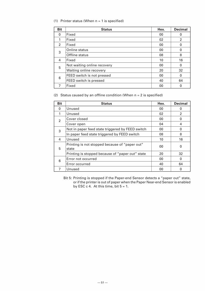
— 51 —
(1) Printer status (When n = 1 is specified)
(2) Status caused by an offline condition (When n = 2 is specified)
Bit 5: Printing is stopped if the Paper-end Sensor detects a “paper out” state,or if the printer is out of paper when the Paper Near-end Sensor is enabledby ESC c 4. At this time, bit 5 = 1.
Bit Status Hex. Decimal
0 Fixed 00 01 Fixed 02 22 Fixed 00 0
3Online status 00 0Offline status 08 8
4 Fixed 10 16
5Not waiting online recovery 00 0Waiting online recovery 20 32
6FEED switch is not pressed 00 0FEED switch is pressed 40 64
7 Fixed 00 0
Bit Status Hex. Decimal
0 Unused 00 01 Unused 02 2
2 Cover closed 00 0Cover open 04 4
3 Not in paper feed state triggered by FEED switch 00 0In paper feed state triggered by FEED switch 08 8
4 Unused 10 16Printing is not stopped because of “paper out” 00 0
5 statePrinting is stopped because of “paper out” state 20 32
6 Error not occurred 00 0Error occurred 40 64
7 Unused 00 0
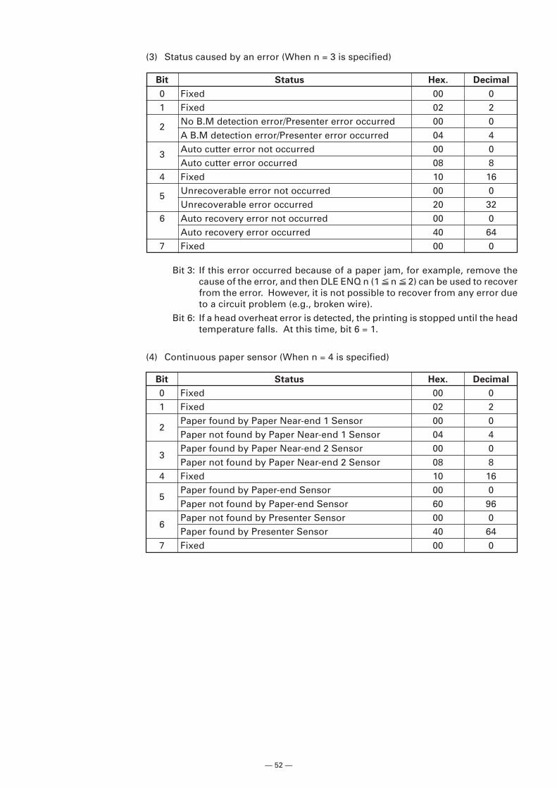
— 52 —
(3) Status caused by an error (When n = 3 is specified)
Bit 3: If this error occurred because of a paper jam, for example, remove thecause of the error, and then DLE ENQ n (1 n 2) can be used to recoverfrom the error. However, it is not possible to recover from any error dueto a circuit problem (e.g., broken wire).
Bit 6: If a head overheat error is detected, the printing is stopped until the headtemperature falls. At this time, bit 6 = 1.
(4) Continuous paper sensor (When n = 4 is specified)
Bit Status Hex. Decimal
0 Fixed 00 01 Fixed 02 2
2 No B.M detection error/Presenter error occurred 00 0A B.M detection error/Presenter error occurred 04 4
3 Auto cutter error not occurred 00 0Auto cutter error occurred 08 8
4 Fixed 10 16
5 Unrecoverable error not occurred 00 0Unrecoverable error occurred 20 32
6 Auto recovery error not occurred 00 0Auto recovery error occurred 40 64
7 Fixed 00 0
Bit Status Hex. Decimal
0 Fixed 00 01 Fixed 02 2
2Paper found by Paper Near-end 1 Sensor 00 0Paper not found by Paper Near-end 1 Sensor 04 4
3Paper found by Paper Near-end 2 Sensor 00 0Paper not found by Paper Near-end 2 Sensor 08 8
4 Fixed 10 16
5Paper found by Paper-end Sensor 00 0Paper not found by Paper-end Sensor 60 96
6Paper not found by Presenter Sensor 00 0Paper found by Presenter Sensor 40 64
7 Fixed 00 0
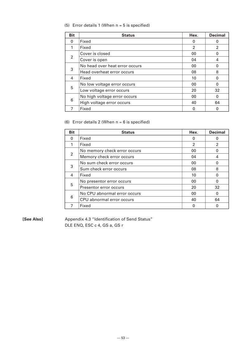
— 53 —
Bit Status Hex. Decimal
0 Fixed 0 01 Fixed 2 2
2Cover is closed 00 0Cover is open 04 4
3No head over heat error occurs 00 0Head overheat error occurs 08 8
4 Fixed 10 0
5No low voltage error occurs 00 0Low voltage error occurs 20 32
6No high voltage error occurs 00 0High voltage error occurs 40 64
7 Fixed 0 0
Bit Status Hex. Decimal
0 Fixed 0 01 Fixed 2 2
2No memory check error occurs 00 0Memory check error occurs 04 4
3No sum check error occurs 00 0Sum check error occurs 08 8
4 Fixed 10 0
5No presentor error occurs 00 0Presentor error occurs 20 32
6No CPU abnormal error occurs 00 0CPU abnormal error occurs 40 64
7 Fixed 0 0
[See Also] Appendix 4.3 “Identification of Send Status”DLE ENQ, ESC c 4, GS a, GS r
(5) Error details 1 (When n = 5 is specified)
(6) Error details 2 (When n = 6 is specified)
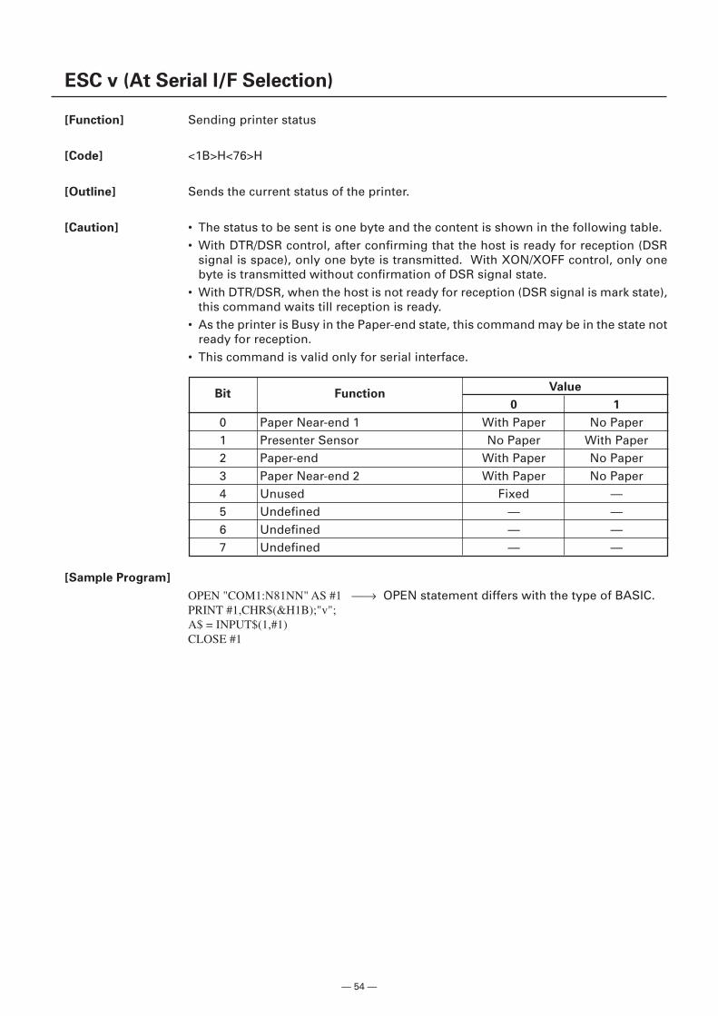
— 54 —
Bit FunctionValue
0 1
0 Paper Near-end 1 With Paper No Paper1 Presenter Sensor No Paper With Paper2 Paper-end With Paper No Paper3 Paper Near-end 2 With Paper No Paper4 Unused Fixed —5 Undefined — —6 Undefined — —7 Undefined — —
ESC v (At Serial I/F Selection)
[Function] Sending printer status
[Code] <1B>H<76>H
[Outline] Sends the current status of the printer.
[Caution] • The status to be sent is one byte and the content is shown in the following table.• With DTR/DSR control, after confirming that the host is ready for reception (DSR
signal is space), only one byte is transmitted. With XON/XOFF control, only onebyte is transmitted without confirmation of DSR signal state.
• With DTR/DSR, when the host is not ready for reception (DSR signal is mark state),this command waits till reception is ready.
• As the printer is Busy in the Paper-end state, this command may be in the state notready for reception.
• This command is valid only for serial interface.
[Sample Program]
OPEN "COM1:N81NN" AS #1 → OPEN statement differs with the type of BASIC.PRINT #1,CHR$(&H1B);"v";A$ = INPUT$(1,#1)CLOSE #1
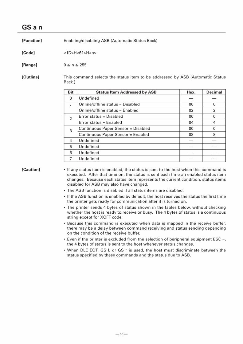
— 55 —
GS a n
[Function] Enabling/disabling ASB (Automatic Status Back)
[Code] <1D>H<61>H<n>
[Range] 0 n 255
[Outline] This command selects the status item to be addressed by ASB (Automatic StatusBack.)
[Caution] • If any status item is enabled, the status is sent to the host when this command isexecuted. After that time on, the status is sent each time an enabled status itemchanges. Because each status item represents the current condition, status itemsdisabled for ASB may also have changed.
• The ASB function is disabled if all status items are disabled.• If the ASB function is enabled by default, the host receives the status the first time
the printer gets ready for communication after it is turned on.• The printer sends 4 bytes of status shown in the tables below, without checking
whether the host is ready to receive or busy. The 4 bytes of status is a continuousstring except for XOFF code.
• Because this command is executed when data is mapped in the receive buffer,there may be a delay between command receiving and status sending dependingon the condition of the receive buffer.
• Even if the printer is excluded from the selection of peripheral equipment ESC =,the 4 bytes of status is sent to the host whenever status changes.
• When DLE EOT, GS I, or GS r is used, the host must discriminate between thestatus specified by these commands and the status due to ASB.
Bit Status Item Addressed by ASB Hex. Decimal
0 Undefined — —
1 Online/offline status = Disabled 00 0Online/offline status = Enabled 02 2
2 Error status = Disabled 00 0Error status = Enabled 04 4
3 Continuous Paper Sensor = Disabled 00 0Continuous Paper Sensor = Enabled 08 8
4 Undefined — —5 Undefined — —6 Undefined — —7 Undefined — —
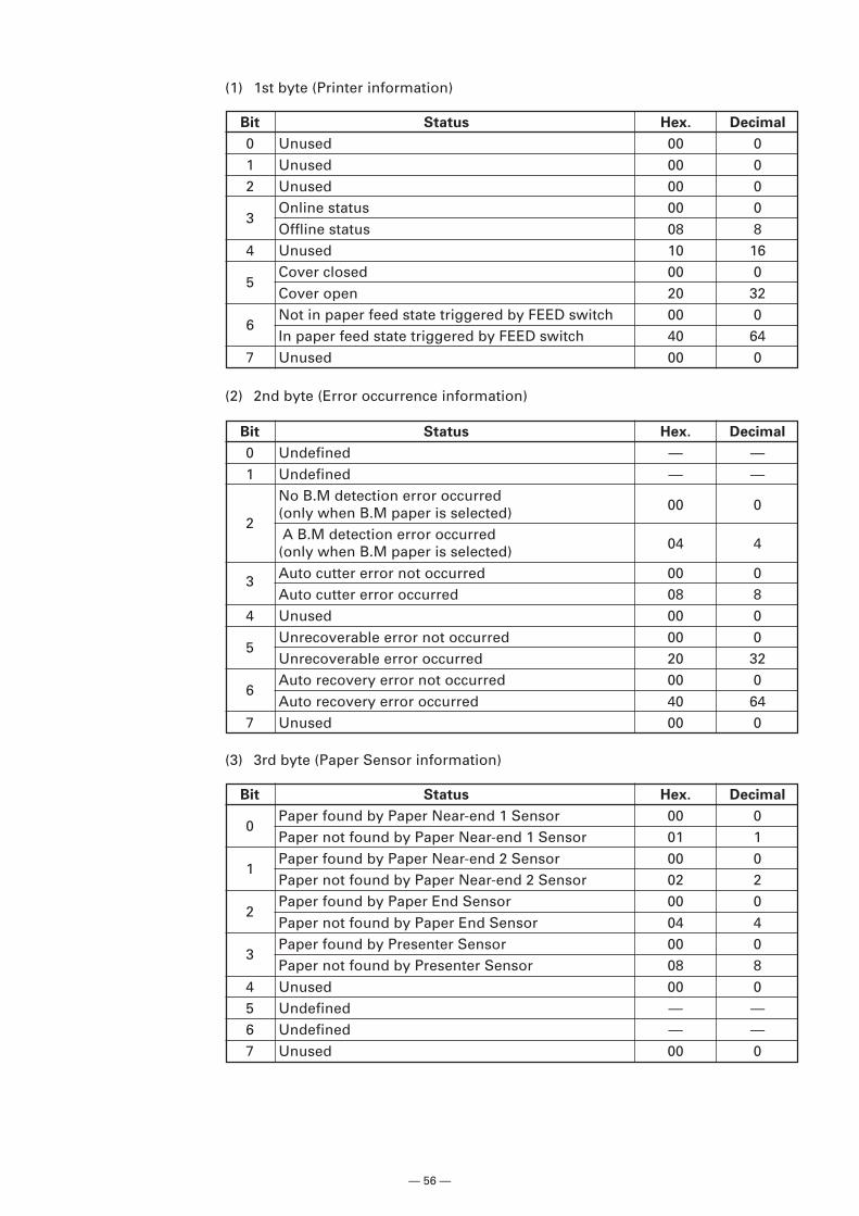
— 56 —
Bit Status Hex. Decimal
0 Unused 00 01 Unused 00 02 Unused 00 0
3Online status 00 0Offline status 08 8
4 Unused 10 16
5Cover closed 00 0Cover open 20 32
6Not in paper feed state triggered by FEED switch 00 0In paper feed state triggered by FEED switch 40 64
7 Unused 00 0
(1) 1st byte (Printer information)
(3) 3rd byte (Paper Sensor information)
(2) 2nd byte (Error occurrence information)
Bit Status Hex. Decimal
0 Undefined — —1 Undefined — —
No B.M detection error occurred
2(only when B.M paper is selected) 00 0
A B.M detection error occurred(only when B.M paper is selected) 04 4
3 Auto cutter error not occurred 00 0Auto cutter error occurred 08 8
4 Unused 00 0
5Unrecoverable error not occurred 00 0Unrecoverable error occurred 20 32
6Auto recovery error not occurred 00 0Auto recovery error occurred 40 64
7 Unused 00 0
Bit Status Hex. Decimal
0Paper found by Paper Near-end 1 Sensor 00 0Paper not found by Paper Near-end 1 Sensor 01 1
1Paper found by Paper Near-end 2 Sensor 00 0Paper not found by Paper Near-end 2 Sensor 02 2
2Paper found by Paper End Sensor 00 0Paper not found by Paper End Sensor 04 4
3Paper found by Presenter Sensor 00 0Paper not found by Presenter Sensor 08 8
4 Unused 00 05 Undefined — —6 Undefined — —7 Unused 00 0
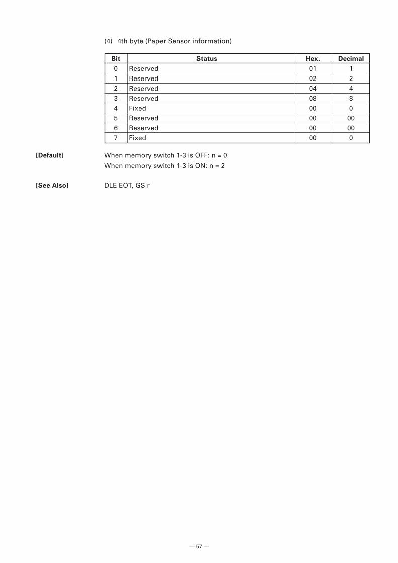
— 57 —
(4) 4th byte (Paper Sensor information)
[Default] When memory switch 1-3 is OFF: n = 0When memory switch 1-3 is ON: n = 2
[See Also] DLE EOT, GS r
Bit Status Hex. Decimal
0 Reserved 01 11 Reserved 02 22 Reserved 04 43 Reserved 08 84 Fixed 00 05 Reserved 00 006 Reserved 00 007 Fixed 00 0
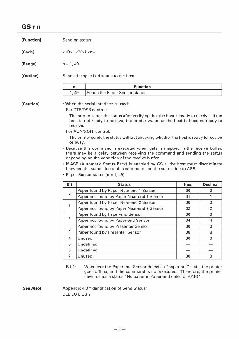
— 58 —
GS r n
[Function] Sending status
[Code] <1D>H<72>H<n>
[Range] n = 1, 49
[Outline] Sends the specified status to the host.
[Caution] • When the serial interface is used:For DTR/DSR control:
The printer sends the status after verifying that the host is ready to receive. If thehost is not ready to receive, the printer waits for the host to become ready toreceive.
For XON/XOFF control:The printer sends the status without checking whether the host is ready to receiveor busy.
• Because this command is executed when data is mapped in the receive buffer,there may be a delay between receiving the command and sending the statusdepending on the condition of the receive buffer.
• If ASB (Automatic Status Back) is enabled by GS a, the host must discriminatebetween the status due to this command and the status due to ASB.
• Paper Sensor status (n = 1, 49)
n Function
1, 49 Sends the Paper Sensor status.
Bit 2: Whenever the Paper-end Sensor detects a “paper out” state, the printergoes offline, and the command is not executed. Therefore, the printernever sends a status “No paper in Paper-end detector (04H)”.
[See Also] Appendix 4.3 “Identification of Send Status”DLE EOT, GS a
Bit Status Hex. Decimal
0Paper found by Paper Near-end 1 Sensor 00 0Paper not found by Paper Near-end 1 Sensor 01 1
1Paper found by Paper Near-end 2 Sensor 00 0Paper not found by Paper Near-end 2 Sensor 02 2
2Paper found by Paper-end Sensor 00 0Paper not found by Paper-end Sensor 04 4
3Paper not found by Presenter Sensor 00 0Paper found by Presenter Sensor 08 8
4 Unused 00 05 Undefined — —6 Undefined — —7 Unused 00 0
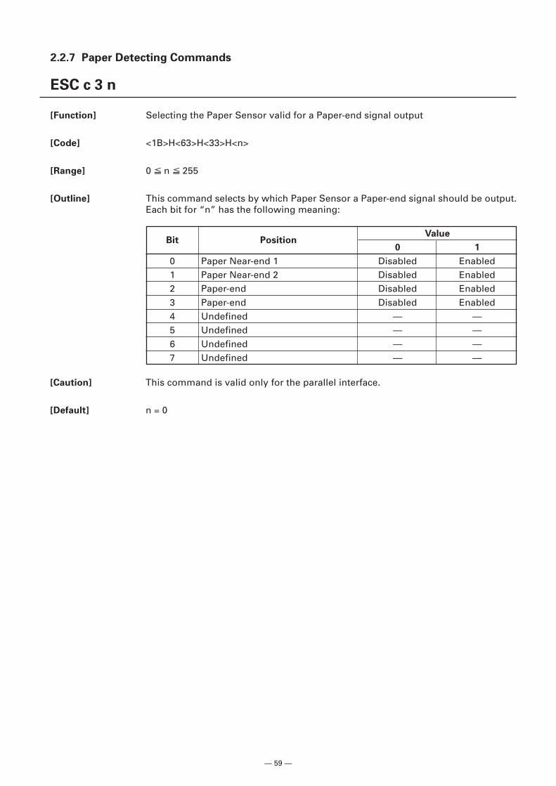
— 59 —
2.2.7 Paper Detecting Commands
ESC c 3 n
[Function] Selecting the Paper Sensor valid for a Paper-end signal output
[Code] <1B>H<63>H<33>H<n>
[Range] 0 n 255
[Outline] This command selects by which Paper Sensor a Paper-end signal should be output.Each bit for “n” has the following meaning:
[Caution] This command is valid only for the parallel interface.
[Default] n = 0
Bit PositionValue
0 1
0 Paper Near-end 1 Disabled Enabled1 Paper Near-end 2 Disabled Enabled2 Paper-end Disabled Enabled3 Paper-end Disabled Enabled4 Undefined — —5 Undefined — —6 Undefined — —7 Undefined — —
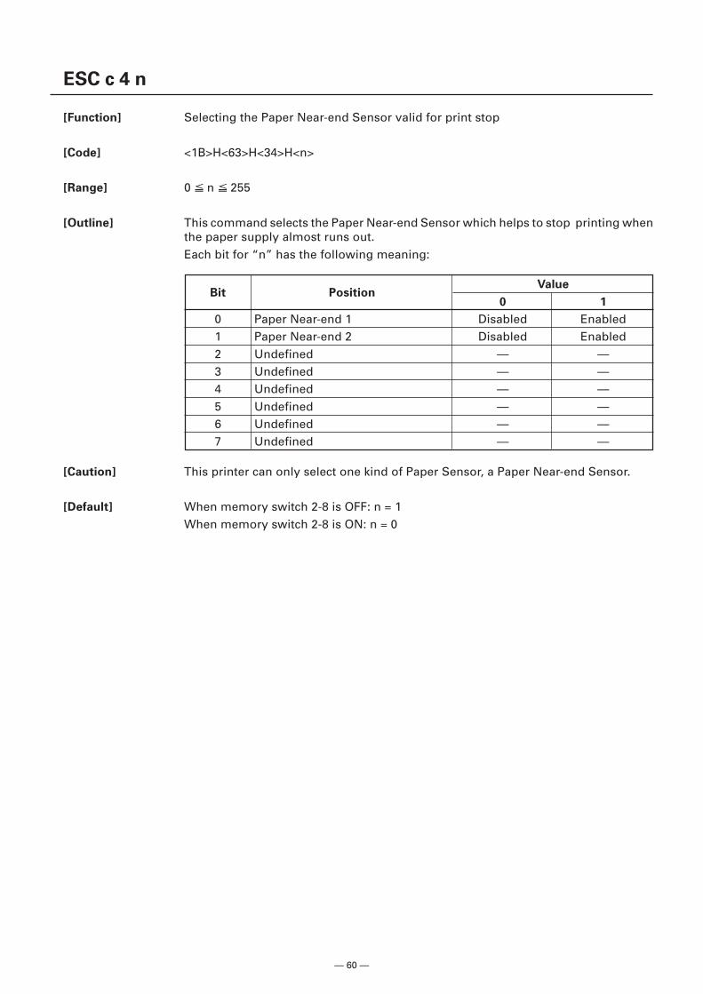
— 60 —
Bit PositionValue
0 1
0 Paper Near-end 1 Disabled Enabled1 Paper Near-end 2 Disabled Enabled2 Undefined — —3 Undefined — —4 Undefined — —5 Undefined — —6 Undefined — —7 Undefined — —
ESC c 4 n
[Function] Selecting the Paper Near-end Sensor valid for print stop
[Code] <1B>H<63>H<34>H<n>
[Range] 0 n 255
[Outline] This command selects the Paper Near-end Sensor which helps to stop printing whenthe paper supply almost runs out.Each bit for “n” has the following meaning:
[Caution] This printer can only select one kind of Paper Sensor, a Paper Near-end Sensor.
[Default] When memory switch 2-8 is OFF: n = 1When memory switch 2-8 is ON: n = 0
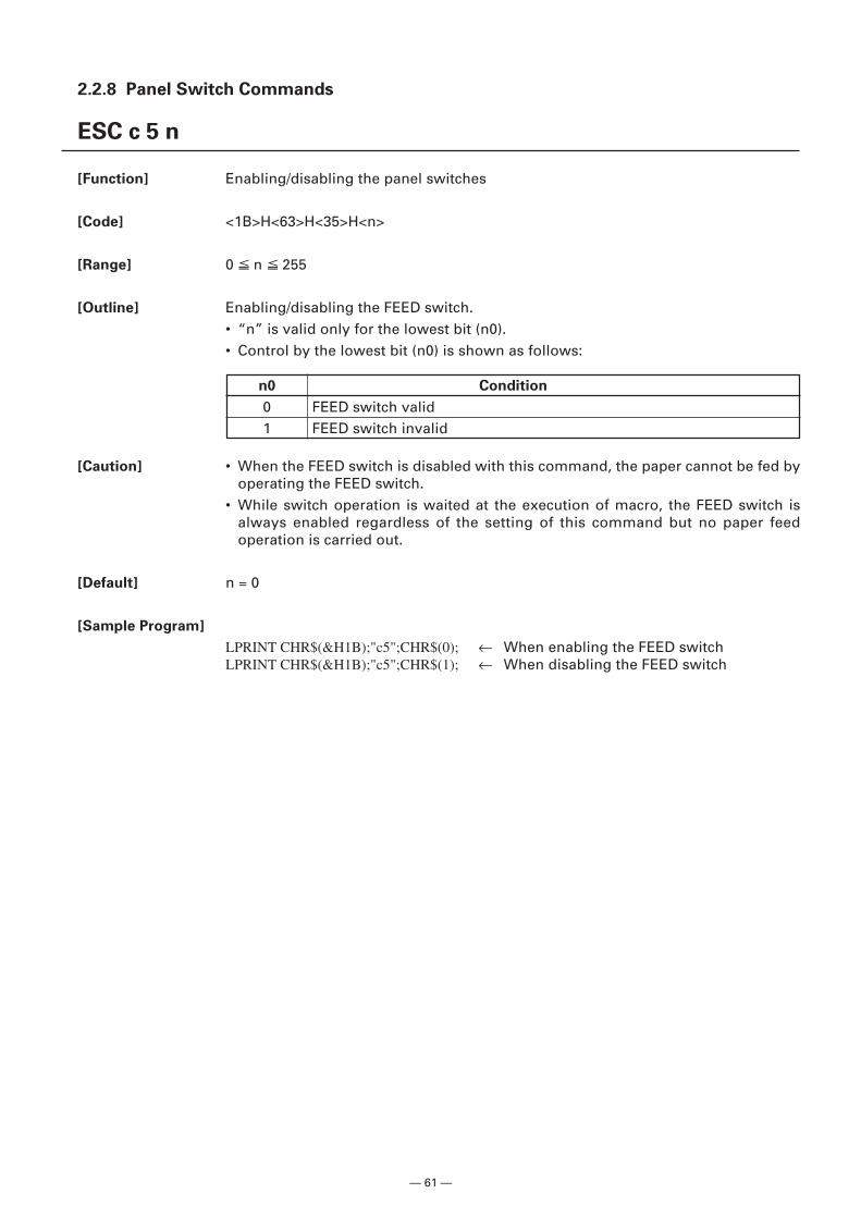
— 61 —
2.2.8 Panel Switch Commands
ESC c 5 n
[Function] Enabling/disabling the panel switches
[Code] <1B>H<63>H<35>H<n>
[Range] 0 n 255
[Outline] Enabling/disabling the FEED switch.• “n” is valid only for the lowest bit (n0).• Control by the lowest bit (n0) is shown as follows:
[Caution] • When the FEED switch is disabled with this command, the paper cannot be fed byoperating the FEED switch.
• While switch operation is waited at the execution of macro, the FEED switch isalways enabled regardless of the setting of this command but no paper feedoperation is carried out.
[Default] n = 0
[Sample Program]
LPRINT CHR$(&H1B);"c5";CHR$(0); ← When enabling the FEED switchLPRINT CHR$(&H1B);"c5";CHR$(1); ← When disabling the FEED switch
n0 Condition
0 FEED switch valid1 FEED switch invalid
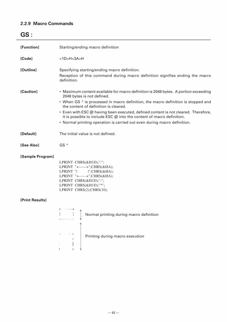
— 62 —
2.2.9 Macro Commands
GS :
[Function] Starting/ending macro definition
[Code] <1D>H<3A>H
[Outline] Specifying starting/ending macro definition.Reception of this command during macro definition signifies ending the macrodefinition.
[Caution] • Maximum content available for macro definition is 2048 bytes. A portion exceeding2048 bytes is not defined.
• When GS ^ is processed in macro definition, the macro definition is stopped andthe content of definition is cleared.
• Even with ESC @ having been executed, defined content is not cleared. Therefore,it is possible to include ESC @ into the content of macro definition.
• Normal printing operation is carried out even during macro definition.
[Default] The initial value is not defined.
[See Also] GS ^
[Sample Program]
LPRINT CHR$(&H1D);":";LPRINT "+------+";CHR$(&HA);LPRINT "| |";CHR$(&HA);LPRINT "+------+";CHR$(&HA);LPRINT CHR$(&H1D);":";LPRINT CHR$(&H1D);"^";LPRINT CHR$(2);CHR$(10);
[Print Results]
Printing during macro execution
Normal printing during macro definition
<
<
<
<
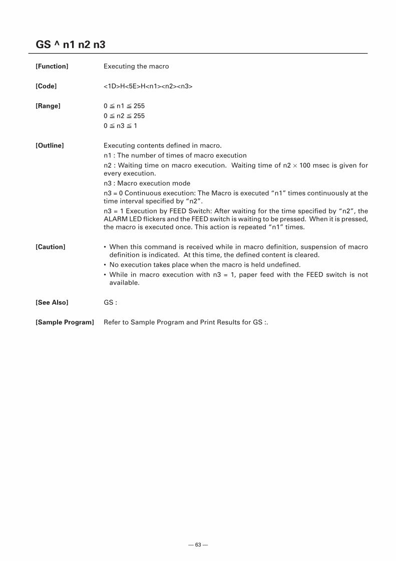
— 63 —
GS ^ n1 n2 n3
[Function] Executing the macro
[Code] <1D>H<5E>H<n1><n2><n3>
[Range] 0 n1 2550 n2 2550 n3 1
[Outline] Executing contents defined in macro.n1 : The number of times of macro executionn2 : Waiting time on macro execution. Waiting time of n2 × 100 msec is given forevery execution.n3 : Macro execution moden3 = 0 Continuous execution: The Macro is executed “n1” times continuously at thetime interval specified by “n2”.n3 = 1 Execution by FEED Switch: After waiting for the time specified by “n2”, theALARM LED flickers and the FEED switch is waiting to be pressed. When it is pressed,the macro is executed once. This action is repeated “n1” times.
[Caution] • When this command is received while in macro definition, suspension of macrodefinition is indicated. At this time, the defined content is cleared.
• No execution takes place when the macro is held undefined.• While in macro execution with n3 = 1, paper feed with the FEED switch is not
available.
[See Also] GS :
[Sample Program] Refer to Sample Program and Print Results for GS :.
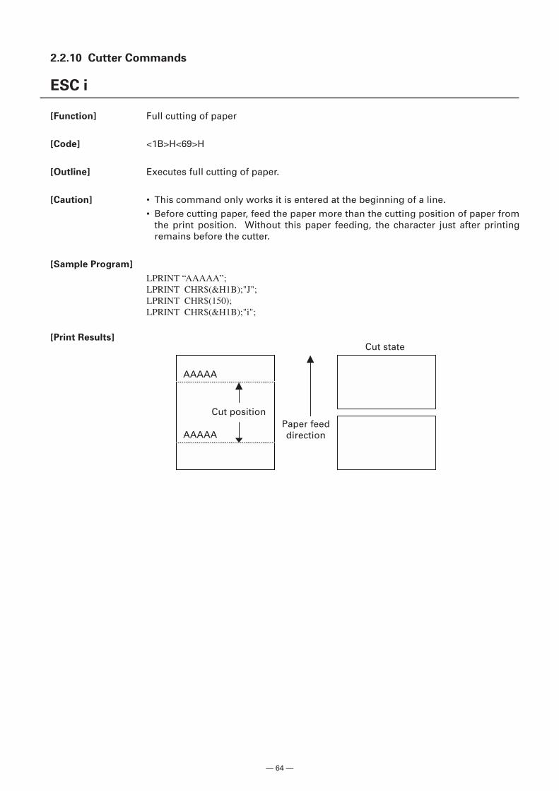
— 64 —
2.2.10 Cutter Commands
ESC i
[Function] Full cutting of paper
[Code] <1B>H<69>H
[Outline] Executes full cutting of paper.
[Caution] • This command only works it is entered at the beginning of a line.• Before cutting paper, feed the paper more than the cutting position of paper from
the print position. Without this paper feeding, the character just after printingremains before the cutter.
[Sample Program]
LPRINT “AAAAA”;LPRINT CHR$(&H1B);"J";LPRINT CHR$(150);LPRINT CHR$(&H1B);"i";
[Print Results]
AAAAA
AAAAA
Cut positionPaper feeddirection
Cut state
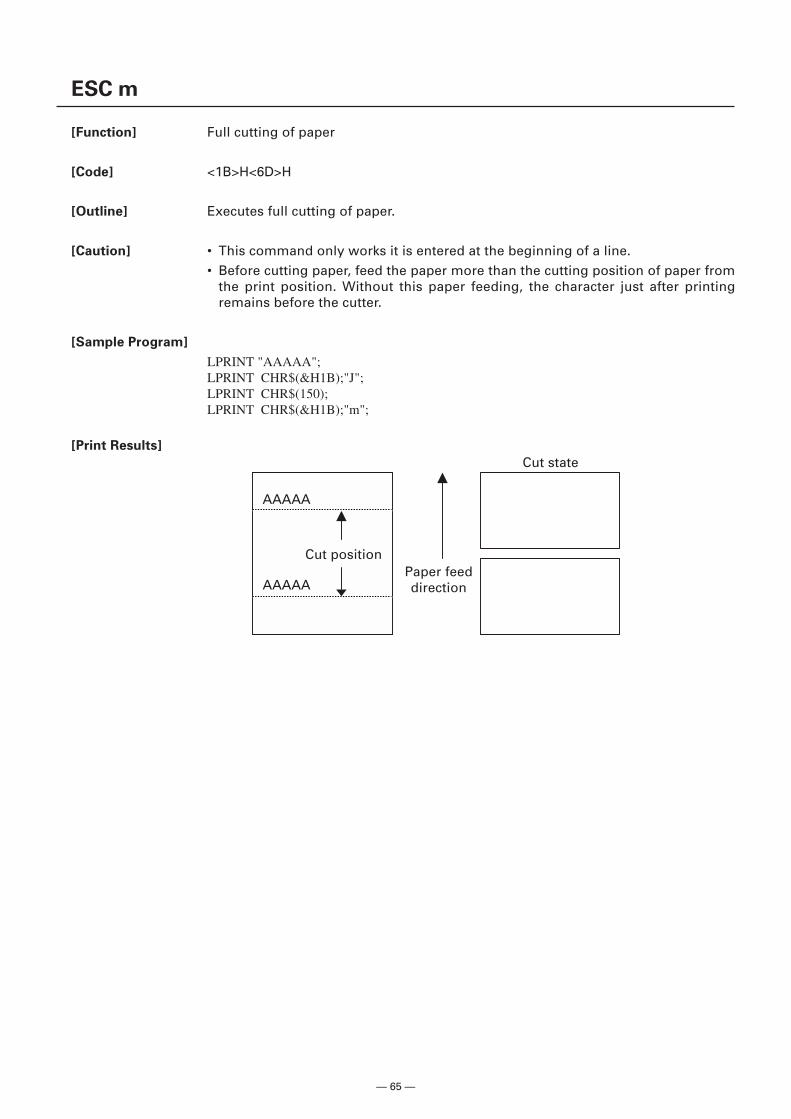
— 65 —
AAAAA
AAAAA
ESC m
[Function] Full cutting of paper
[Code] <1B>H<6D>H
[Outline] Executes full cutting of paper.
[Caution] • This command only works it is entered at the beginning of a line.• Before cutting paper, feed the paper more than the cutting position of paper from
the print position. Without this paper feeding, the character just after printingremains before the cutter.
[Sample Program]
LPRINT "AAAAA";LPRINT CHR$(&H1B);"J";LPRINT CHR$(150);LPRINT CHR$(&H1B);"m";
[Print Results]
Cut positionPaper feeddirection
Cut state
— 66 —
GS V m ......... (1)
GS V m n ...... (2)
[Function] Cutting the paper
[Code] (1) <1D>H<56>H<m>(2) <1D>H<56>H<m><n>
[Range] (1) m = 0, 1, m = 48, 49(2) m = 65, 66
[Outline] Performs the specified paper cutting.
[Caution] • In STANDARD MODE, this command only works when it is entered at the beginningof a line.
• Control to make the length of cut paper less than 10 mm is not executed.
For (1):• Executes cutting of paper.
For (2):• If n = 0, the paper is fed to the cut position, and then cut. If n ≠ 0, the paper is fed by
“n × basic calculation pitch” inches past the cut position, and then cut.• The basic calculation pitch is set by GS P.• The paper feed amount is calculated with the vertical basic calculation pitch (y). A
fraction resulting from the calculation is corrected with the minimum pitch of themechanism, and the remainder is omitted.
m Function
0, 48 Full cut1, 49 Full cut
65 Paper feed by “cut position + basic calculation pitch” and full cut66 Paper feed by “cut position + basic calculation pitch” and full cut
— 67 —
2.2.11 Bar Code Commands
GS H n
[Function] Selecting of printing position of HRI characters
[Code] <1D>H<48>H<n>
[Range] 0 n 348 n 51
[Outline] Selecting printing position of HRI characters in printing bar codes.“n” means the followings.
n Printing Position
0, 48 No printing1, 49 Above the bar code2, 50 Below the bar code3, 51 Both above and below the bar code
The HRI characters refer to the bar code-turned characters so that you can read them.
[Caution] • The HRI characters are printed in the font selected with GS f.• Specify before the GS k command.
[Default] n = 0
[See Also] GS f, GS k
[Sample Program]
LPRINT CHR$(&H1B);"3";CHR$(5);LPRINT CHR$(&H1D);"h";CHR$(50);LPRINT CHR$(&H1D);"H";CHR$(0);GOSUB BCLPRINT CHR$(&H1D);"H";CHR$(1);GOSUB BCLPRINT CHR$(&H1D);"H";CHR$(2);GOSUB BCLPRINT CHR$(&H1D);"H";CHR$(3);GOSUB BCENDBC:LPRINT CHR$(&H1D);"k";LPRINT CHR$(4);LPRINT "12";CHR$(0);LPRINT CHR$(&HA);RETURN
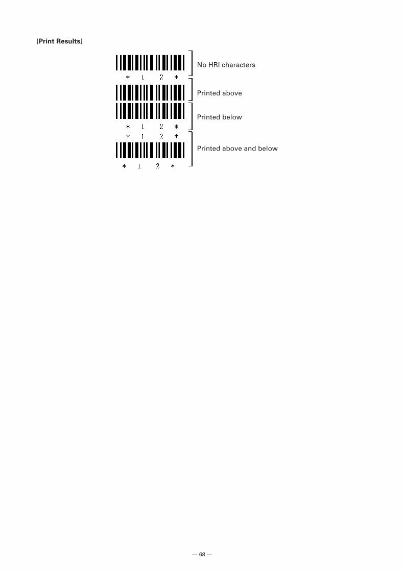
— 68 —
Printed above and below
No HRI characters
Printed above
Printed below
[Print Results]
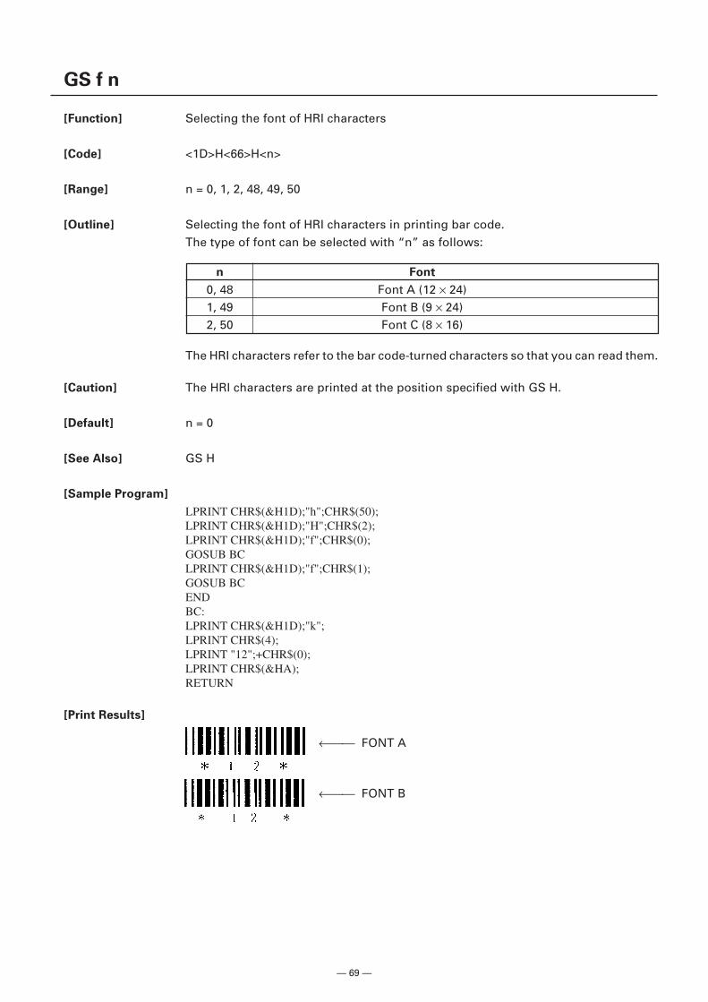
— 69 —
GS f n
[Function] Selecting the font of HRI characters
[Code] <1D>H<66>H<n>
[Range] n = 0, 1, 2, 48, 49, 50
[Outline] Selecting the font of HRI characters in printing bar code.The type of font can be selected with “n” as follows:
The HRI characters refer to the bar code-turned characters so that you can read them.
[Caution] The HRI characters are printed at the position specified with GS H.
[Default] n = 0
[See Also] GS H
[Sample Program]
LPRINT CHR$(&H1D);"h";CHR$(50);LPRINT CHR$(&H1D);"H";CHR$(2);LPRINT CHR$(&H1D);"f";CHR$(0);GOSUB BCLPRINT CHR$(&H1D);"f";CHR$(1);GOSUB BCENDBC:LPRINT CHR$(&H1D);"k";LPRINT CHR$(4);LPRINT "12";+CHR$(0);LPRINT CHR$(&HA);RETURN
[Print Results]
n Font
0, 48 Font A (12 × 24)1, 49 Font B (9 × 24)2, 50 Font C (8 × 16)
← FONT A
← FONT B
— 70 —
GS h n
[Function] Specifying the height of the bar code
[Code] <1D>H<68>H<n>
[Range] 1 n 255
[Outline] Selecting bar code height.“n” denotes the number of dots in the vertical direction.
[Default] n = 162
[See Also] GS k, GS w
[Sample Program] Refer to Sample Program and Print Results for GS w.
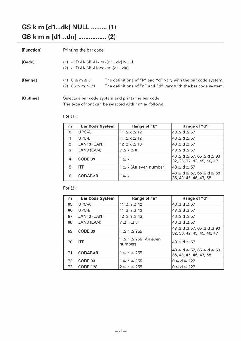
— 71 —
GS k m [d1...dk] NULL ......... (1)
GS k m n [d1...dn] ................ (2)
[Function] Printing the bar code
[Code] (1) <1D>H<6B>H <m>[d1...dk] NULL(2) <1D>H<6B>H<m><n>[d1...dn]
[Range] (1) 0 m 6 The definitions of “k” and “d” vary with the bar code system.(2) 65 m 73 The definitions of “n” and “d” vary with the bar code system.
[Outline] Selects a bar code system and prints the bar code.The type of font can be selected with “n” as follows.
For (1):
m Bar Code System Range of “k” Range of “d”
0 UPC-A 11 k 12 48 d 571 UPC-E 11 k 12 48 d 572 JAN13 (EAN) 12 k 13 48 d 573 JAN8 (EAN) 7 k 8 48 d 57
4 CODE 39 1 k48 d 57, 65 d 9032, 36, 37, 43, 45, 46, 47
5 ITF 1 k (An even number) 48 d 57
6 CODABAR 1 k48 d 57, 65 d 6836, 43, 45, 46, 47, 58
m Bar Code System Range of “n” Range of “d”
65 UPC-A 11 n 12 48 d 5766 UPC-E 11 n 12 48 d 5767 JAN13 (EAN) 12 n 13 48 d 5768 JAN8 (EAN) 7 n 8 48 d 57
69 CODE 39 1 n 25548 d 57, 65 d 9032, 36, 42, 43, 45, 46, 47
70 ITF1 n 255 (An even
48 d 57number)
71 CODABAR 1 n 25548 d 57, 65 d 6836, 43, 45, 46, 47, 58
72 CODE 93 1 n 255 0 d 12773 CODE 128 2 n 255 0 d 127
For (2):
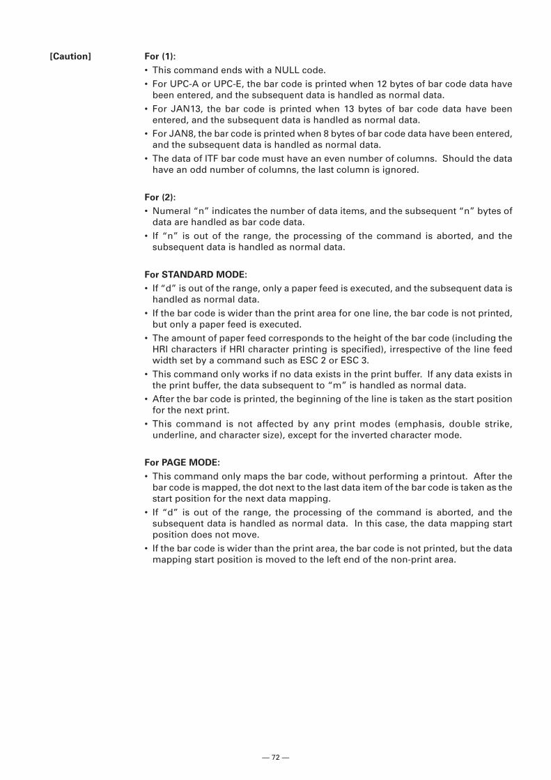
— 72 —
[Caution] For (1):
• This command ends with a NULL code.• For UPC-A or UPC-E, the bar code is printed when 12 bytes of bar code data have
been entered, and the subsequent data is handled as normal data.• For JAN13, the bar code is printed when 13 bytes of bar code data have been
entered, and the subsequent data is handled as normal data.• For JAN8, the bar code is printed when 8 bytes of bar code data have been entered,
and the subsequent data is handled as normal data.• The data of ITF bar code must have an even number of columns. Should the data
have an odd number of columns, the last column is ignored.
For (2):
• Numeral “n” indicates the number of data items, and the subsequent “n” bytes ofdata are handled as bar code data.
• If “n” is out of the range, the processing of the command is aborted, and thesubsequent data is handled as normal data.
For STANDARD MODE:
• If “d” is out of the range, only a paper feed is executed, and the subsequent data ishandled as normal data.
• If the bar code is wider than the print area for one line, the bar code is not printed,but only a paper feed is executed.
• The amount of paper feed corresponds to the height of the bar code (including theHRI characters if HRI character printing is specified), irrespective of the line feedwidth set by a command such as ESC 2 or ESC 3.
• This command only works if no data exists in the print buffer. If any data exists inthe print buffer, the data subsequent to “m” is handled as normal data.
• After the bar code is printed, the beginning of the line is taken as the start positionfor the next print.
• This command is not affected by any print modes (emphasis, double strike,underline, and character size), except for the inverted character mode.
For PAGE MODE:
• This command only maps the bar code, without performing a printout. After thebar code is mapped, the dot next to the last data item of the bar code is taken as thestart position for the next data mapping.
• If “d” is out of the range, the processing of the command is aborted, and thesubsequent data is handled as normal data. In this case, the data mapping startposition does not move.
• If the bar code is wider than the print area, the bar code is not printed, but the datamapping start position is moved to the left end of the non-print area.
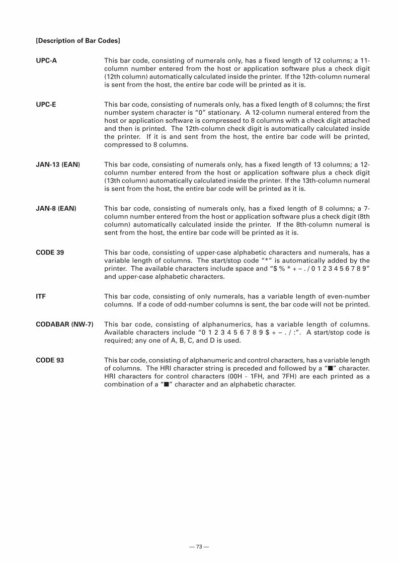
— 73 —
[Description of Bar Codes]
UPC-A This bar code, consisting of numerals only, has a fixed length of 12 columns; a 11-column number entered from the host or application software plus a check digit(12th column) automatically calculated inside the printer. If the 12th-column numeralis sent from the host, the entire bar code will be printed as it is.
UPC-E This bar code, consisting of numerals only, has a fixed length of 8 columns; the firstnumber system character is “0” stationary. A 12-column numeral entered from thehost or application software is compressed to 8 columns with a check digit attachedand then is printed. The 12th-column check digit is automatically calculated insidethe printer. If it is and sent from the host, the entire bar code will be printed,compressed to 8 columns.
JAN-13 (EAN) This bar code, consisting of numerals only, has a fixed length of 13 columns; a 12-column number entered from the host or application software plus a check digit(13th column) automatically calculated inside the printer. If the 13th-column numeralis sent from the host, the entire bar code will be printed as it is.
JAN-8 (EAN) This bar code, consisting of numerals only, has a fixed length of 8 columns; a 7-column number entered from the host or application software plus a check digit (8thcolumn) automatically calculated inside the printer. If the 8th-column numeral issent from the host, the entire bar code will be printed as it is.
CODE 39 This bar code, consisting of upper-case alphabetic characters and numerals, has avariable length of columns. The start/stop code “*” is automatically added by theprinter. The available characters include space and “$ % * + – . / 0 1 2 3 4 5 6 7 8 9”and upper-case alphabetic characters.
ITF This bar code, consisting of only numerals, has a variable length of even-numbercolumns. If a code of odd-number columns is sent, the bar code will not be printed.
CODABAR (NW-7) This bar code, consisting of alphanumerics, has a variable length of columns.Available characters include “0 1 2 3 4 5 6 7 8 9 $ + – . / :”. A start/stop code isrequired; any one of A, B, C, and D is used.
CODE 93 This bar code, consisting of alphanumeric and control characters, has a variable lengthof columns. The HRI character string is preceded and followed by a “�” character.HRI characters for control characters (00H - 1FH, and 7FH) are each printed as acombination of a “�” character and an alphabetic character.
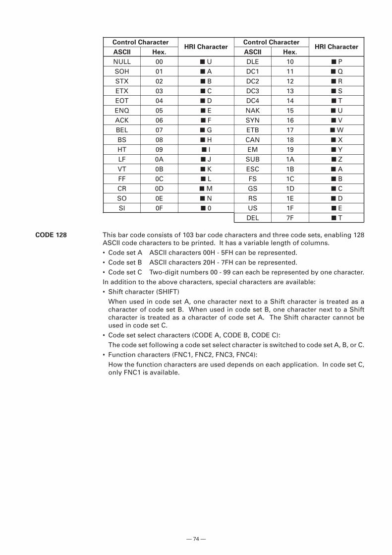
— 74 —
Control Character Control Character
ASCII Hex. ASCII Hex.
NULL 00 � U DLE 10 � PSOH 01 � A DC1 11 � QSTX 02 � B DC2 12 � RETX 03 � C DC3 13 � SEOT 04 � D DC4 14 � TENQ 05 � E NAK 15 � UACK 06 � F SYN 16 � VBEL 07 � G ETB 17 � WBS 08 � H CAN 18 � XHT 09 � I EM 19 � YLF 0A � J SUB 1A � ZVT 0B � K ESC 1B � AFF 0C � L FS 1C � BCR 0D � M GS 1D � CSO 0E � N RS 1E � DSI 0F � 0 US 1F � E
DEL 7F � T
CODE 128 This bar code consists of 103 bar code characters and three code sets, enabling 128ASCII code characters to be printed. It has a variable length of columns.• Code set A ASCII characters 00H - 5FH can be represented.• Code set B ASCII characters 20H - 7FH can be represented.• Code set C Two-digit numbers 00 - 99 can each be represented by one character.In addition to the above characters, special characters are available:• Shift character (SHIFT)
When used in code set A, one character next to a Shift character is treated as acharacter of code set B. When used in code set B, one character next to a Shiftcharacter is treated as a character of code set A. The Shift character cannot beused in code set C.
• Code set select characters (CODE A, CODE B, CODE C):The code set following a code set select character is switched to code set A, B, or C.
• Function characters (FNC1, FNC2, FNC3, FNC4):How the function characters are used depends on each application. In code set C,only FNC1 is available.
HRI Character HRI Character
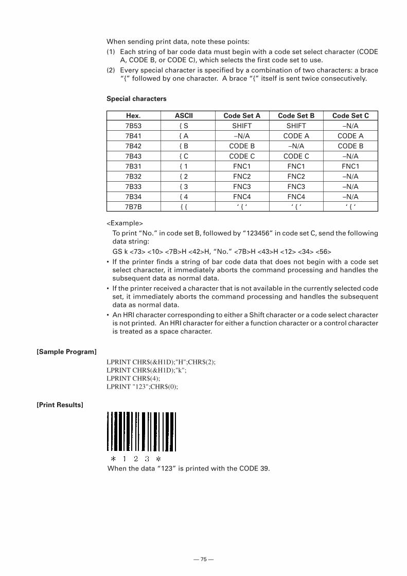
— 75 —
Hex. ASCII Code Set A Code Set B Code Set C
7B53 { S SHIFT SHIFT –N/A7B41 { A –N/A CODE A CODE A7B42 { B CODE B –N/A CODE B7B43 { C CODE C CODE C –N/A7B31 { 1 FNC1 FNC1 FNC17B32 { 2 FNC2 FNC2 –N/A7B33 { 3 FNC3 FNC3 –N/A7B34 { 4 FNC4 FNC4 –N/A7B7B { { ‘ { ‘ ‘ { ‘ ‘ { ‘
When sending print data, note these points:(1) Each string of bar code data must begin with a code set select character (CODE
A, CODE B, or CODE C), which selects the first code set to use.(2) Every special character is specified by a combination of two characters: a brace
“{” followed by one character. A brace “{” itself is sent twice consecutively.
Special characters
<Example>To print “No.” in code set B, followed by “123456” in code set C, send the followingdata string:GS k <73> <10> <7B>H <42>H, “No.” <7B>H <43>H <12> <34> <56>
• If the printer finds a string of bar code data that does not begin with a code setselect character, it immediately aborts the command processing and handles thesubsequent data as normal data.
• If the printer received a character that is not available in the currently selected codeset, it immediately aborts the command processing and handles the subsequentdata as normal data.
• An HRI character corresponding to either a Shift character or a code select characteris not printed. An HRI character for either a function character or a control characteris treated as a space character.
[Sample Program]
LPRINT CHR$(&H1D);"H";CHR$(2);LPRINT CHR$(&H1D);"k";LPRINT CHR$(4);LPRINT "123";CHR$(0);
[Print Results]
When the data “123” is printed with the CODE 39.
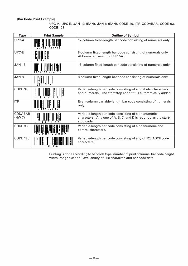
— 76 —
Type Print Sample Outline of Symbol
UPC-A 12-column fixed-length bar code consisting of numerals only.
UPC-E 8-column fixed-length bar code consisting of numerals only.Abbreviated version of UPC-A.
JAN-13 13-column fixed-length bar code consisting of numerals only.
JAN-8 8-column fixed-length bar code consisting of numerals only.
CODE 39 Variable-length bar code consisting of alphabetic charactersand numerals. The start/stop code “*”is automatically added.
ITF Even-column variable-length bar code consisting of numeralsonly.
CODABAR Variable-length bar code consisting of alphanumeric(NW-7) characters. Any one of A, B, C, and D is required as the start/
stop code.CODE 93 Variable-length bar code consisting of alphanumeric and
control characters.
CODE 128 Variable-length bar code consisting of any of 128 ASCII codecharacters.
[Bar Code Print Example]
UPC-A, UPC-E, JAN-13 (EAN), JAN-8 (EAN), CODE 39, ITF, CODABAR, CODE 93,CODE 128
Printing is done according to bar code type, number of print columns, bar code height,width (magnification), availability of HRI character, and bar code data.
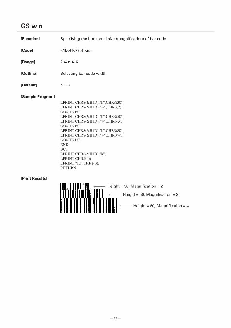
— 77 —
GS w n
[Function] Specifying the horizontal size (magnification) of bar code
[Code] <1D>H<77>H<n>
[Range] 2 n 6
[Outline] Selecting bar code width.
[Default] n = 3
[Sample Program]
LPRINT CHR$(&H1D);"h";CHR$(30);LPRINT CHR$(&H1D);"w";CHR$(2);GOSUB BCLPRINT CHR$(&H1D);"h";CHR$(50);LPRINT CHR$(&H1D);"w";CHR$(3);GOSUB BCLPRINT CHR$(&H1D);"h";CHR$(80);LPRINT CHR$(&H1D);"w";CHR$(4);GOSUB BCENDBC:LPRINT CHR$(&H1D);"k";LPRINT CHR$(4);LPRINT "12";CHR$(0);RETURN
[Print Results]
← Height = 30, Magnification = 2
← Height = 50, Magnification = 3
← Height = 80, Magnification = 4
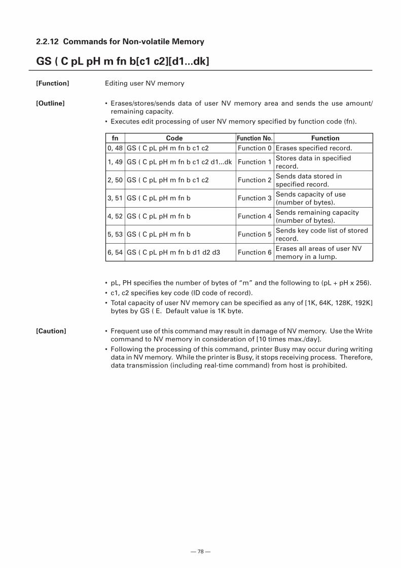
— 78 —
2.2.12 Commands for Non-volatile Memory
GS ( C pL pH m fn b[c1 c2][d1...dk]
[Function] Editing user NV memory
[Outline] • Erases/stores/sends data of user NV memory area and sends the use amount/remaining capacity.
• Executes edit processing of user NV memory specified by function code (fn).
• pL, PH specifies the number of bytes of “m” and the following to (pL + pH x 256).• c1, c2 specifies key code (ID code of record).• Total capacity of user NV memory can be specified as any of [1K, 64K, 128K, 192K]
bytes by GS ( E. Default value is 1K byte.
[Caution] • Frequent use of this command may result in damage of NV memory. Use the Writecommand to NV memory in consideration of [10 times max./day].
• Following the processing of this command, printer Busy may occur during writingdata in NV memory. While the printer is Busy, it stops receiving process. Therefore,data transmission (including real-time command) from host is prohibited.
fn Code Function No. Function
0, 48 GS ( C pL pH m fn b c1 c2 Function 0 Erases specified record.
1, 49 GS ( C pL pH m fn b c1 c2 d1...dk Function 1 Stores data in specifiedrecord.
2, 50 GS ( C pL pH m fn b c1 c2 Function 2 Sends data stored inspecified record.
3, 51 GS ( C pL pH m fn b Function 3 Sends capacity of use(number of bytes).
4, 52 GS ( C pL pH m fn b Function 4 Sends remaining capacity(number of bytes).
5, 53 GS ( C pL pH m fn b Function 5 Sends key code list of storedrecord.
6, 54 GS ( C pL pH m fn b d1 d2 d3 Function 6 Erases all areas of user NVmemory in a lump.
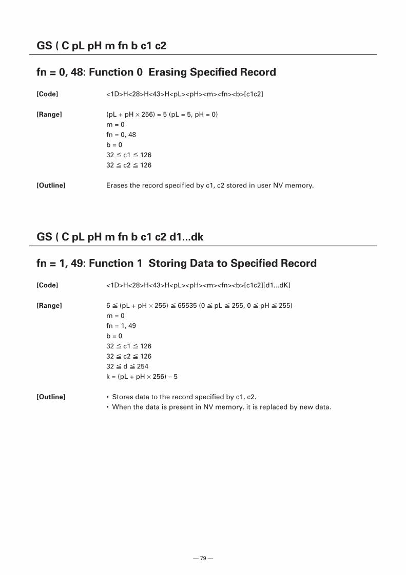
— 79 —
GS ( C pL pH m fn b c1 c2
fn = 0, 48: Function 0 Erasing Specified Record
[Code] <1D>H<28>H<43>H<pL><pH><m><fn><b>[c1c2]
[Range] (pL + pH × 256) = 5 (pL = 5, pH = 0)m = 0fn = 0, 48b = 032 c1 12632 c2 126
[Outline] Erases the record specified by c1, c2 stored in user NV memory.
GS ( C pL pH m fn b c1 c2 d1...dk
fn = 1, 49: Function 1 Storing Data to Specified Record
[Code] <1D>H<28>H<43>H<pL><pH><m><fn><b>[c1c2][d1...dK]
[Range] 6 (pL + pH × 256) 65535 (0 pL 255, 0 pH 255)m = 0fn = 1, 49b = 032 c1 12632 c2 12632 d 254k = (pL + pH × 256) – 5
[Outline] • Stores data to the record specified by c1, c2.• When the data is present in NV memory, it is replaced by new data.
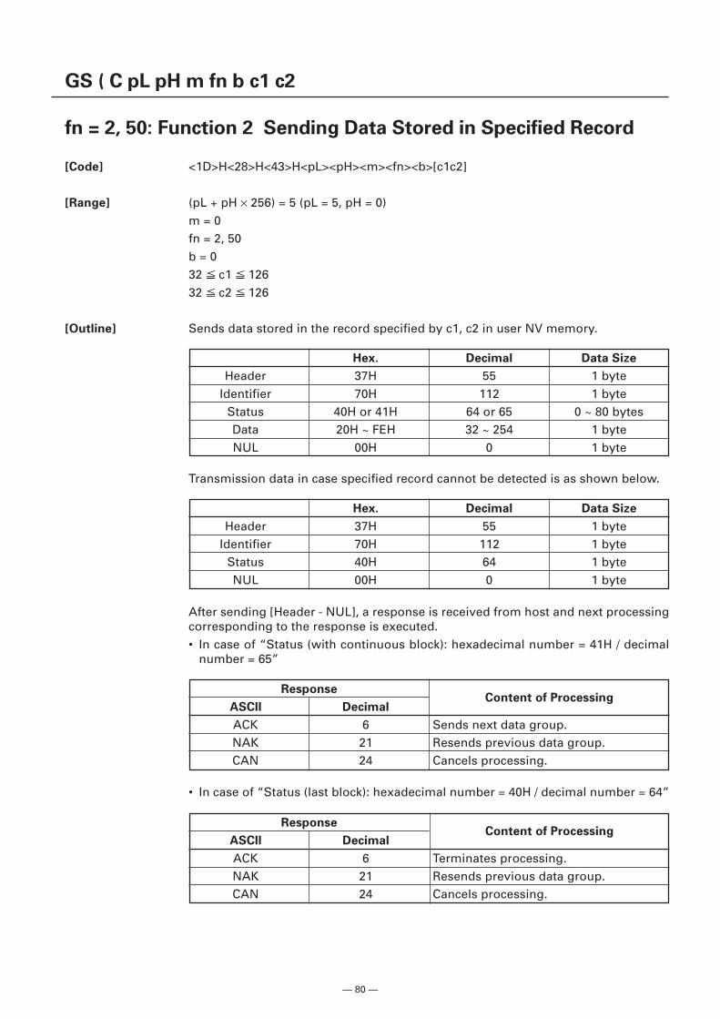
— 80 —
GS ( C pL pH m fn b c1 c2
fn = 2, 50: Function 2 Sending Data Stored in Specified Record
[Code] <1D>H<28>H<43>H<pL><pH><m><fn><b>[c1c2]
[Range] (pL + pH × 256) = 5 (pL = 5, pH = 0)m = 0fn = 2, 50b = 032 c1 12632 c2 126
[Outline] Sends data stored in the record specified by c1, c2 in user NV memory.
Hex. Decimal Data Size
Header 37H 55 1 byteIdentifier 70H 112 1 byte
Status 40H or 41H 64 or 65 0 ~ 80 bytesData 20H ~ FEH 32 ~ 254 1 byteNUL 00H 0 1 byte
Hex. Decimal Data Size
Header 37H 55 1 byteIdentifier 70H 112 1 byte
Status 40H 64 1 byteNUL 00H 0 1 byte
ResponseContent of Processing
ASCII Decimal
ACK 6 Sends next data group.NAK 21 Resends previous data group.CAN 24 Cancels processing.
ResponseContent of Processing
ASCII Decimal
ACK 6 Terminates processing.NAK 21 Resends previous data group.CAN 24 Cancels processing.
Transmission data in case specified record cannot be detected is as shown below.
After sending [Header - NUL], a response is received from host and next processingcorresponding to the response is executed.• In case of “Status (with continuous block): hexadecimal number = 41H / decimal
number = 65”
• In case of “Status (last block): hexadecimal number = 40H / decimal number = 64”
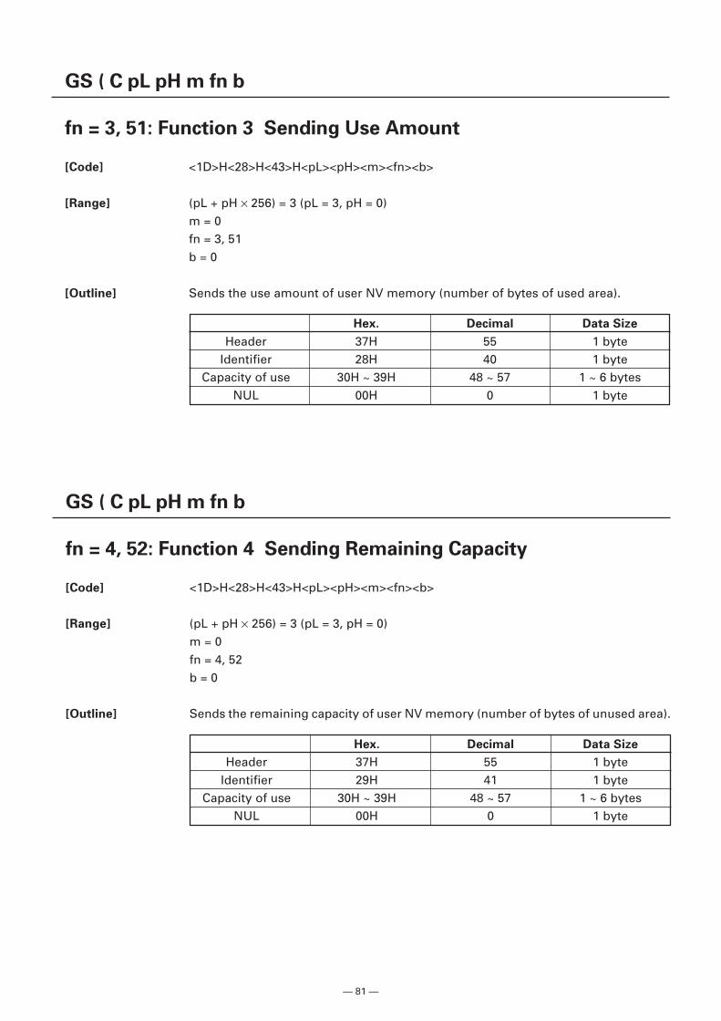
— 81 —
GS ( C pL pH m fn b
fn = 3, 51: Function 3 Sending Use Amount
[Code] <1D>H<28>H<43>H<pL><pH><m><fn><b>
[Range] (pL + pH × 256) = 3 (pL = 3, pH = 0)m = 0fn = 3, 51b = 0
[Outline] Sends the use amount of user NV memory (number of bytes of used area).
Hex. Decimal Data Size
Header 37H 55 1 byteIdentifier 28H 40 1 byte
Capacity of use 30H ~ 39H 48 ~ 57 1 ~ 6 bytesNUL 00H 0 1 byte
GS ( C pL pH m fn b
fn = 4, 52: Function 4 Sending Remaining Capacity
[Code] <1D>H<28>H<43>H<pL><pH><m><fn><b>
[Range] (pL + pH × 256) = 3 (pL = 3, pH = 0)m = 0fn = 4, 52b = 0
[Outline] Sends the remaining capacity of user NV memory (number of bytes of unused area).
Hex. Decimal Data Size
Header 37H 55 1 byteIdentifier 29H 41 1 byte
Capacity of use 30H ~ 39H 48 ~ 57 1 ~ 6 bytesNUL 00H 0 1 byte
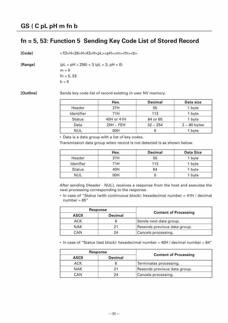
— 82 —
GS ( C pL pH m fn b
fn = 5, 53: Function 5 Sending Key Code List of Stored Record
[Code] <1D>H<28>H<43>H<pL><pH><m><fn><b>
[Range] (pL + pH × 256) = 3 (pL = 3, pH = 0)m = 0fn = 5, 53b = 0
[Outline] Sends key code list of record existing in user NV memory.
Hex. Decimal Data size
Header 37H 55 1 byteIdentifier 71H 113 1 byte
Status 40H or 41H 64 or 65 1 byteData 20H ~ FEH 32 ~ 254 2 ~ 80 bytesNUL 00H 0 1 byte
Hex. Decimal Data Size
Header 37H 55 1 byteIdenifier 71H 113 1 byteStatus 40H 64 1 byteNUL 00H 0 1 byte
ResponseContent of Processing
ASCII Decimal
ACK 6 Sends next data group.NAK 21 Resends previous data group.CAN 24 Cancels processing.
ResponseContent of Processing
ASCII Decimal
ACK 6 Terminates processing.NAK 21 Resends previous data group.CAN 24 Cancels processing.
• Data is a data group with a list of key codes.Transmission data group when record is not detected is as shown below.
After sending [Header - NUL], receives a response from the host and executes thenext processing corresponding to the response.• In case of “Status (with continuous block): hexadecimal number = 41H / decimal
number = 65”
• In case of “Status (last block): hexadecimal number = 40H / decimal number = 64”
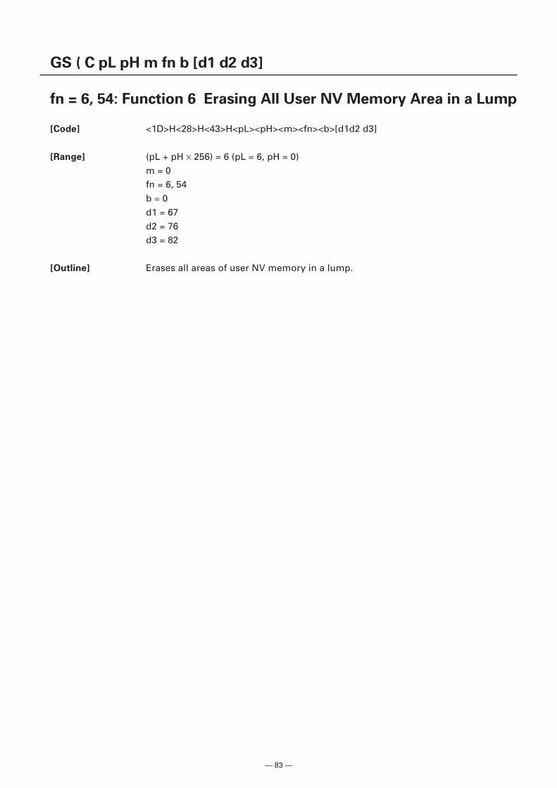
— 83 —
GS ( C pL pH m fn b [d1 d2 d3]
fn = 6, 54: Function 6 Erasing All User NV Memory Area in a Lump
[Code] <1D>H<28>H<43>H<pL><pH><m><fn><b>[d1d2 d3]
[Range] (pL + pH × 256) = 6 (pL = 6, pH = 0)m = 0fn = 6, 54b = 0d1 = 67d2 = 76d3 = 82
[Outline] Erases all areas of user NV memory in a lump.
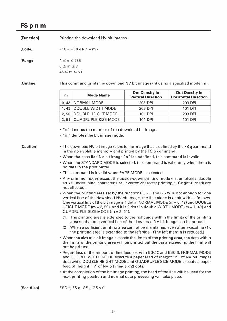
— 84 —
FS p n m
[Function] Printing the download NV bit images
[Code] <1C>H<70>H<n><m>
[Range] 1 n 2550 m 348 m 51
[Outline] This command prints the download NV bit images (n) using a specified mode (m).
• “n” denotes the number of the download bit image.• “m” denotes the bit image mode.
[Caution] • The download NV bit image refers to the image that is defined by the FS q commandin the non-volatile memory and printed by the FS p command.
• When the specified NV bit image “n” is undefined, this command is invalid.• When the STANDARD MODE is selected, this command is valid only when there is
no data in the print buffer.• This command is invalid when PAGE MODE is selected.• Any printing modes except the upside-down printing mode (i.e. emphasis, double
strike, underlining, character size, inverted character printing, 90˚-right-turned) arenot affected.
• When the printing area set by the functions GS L and GS W is not enough for onevertical line of the download NV bit image, the line alone is dealt with as follows.One vertical line of the bit image is 1 dot in NORMAL MODE (m = 0, 48) and DOUBLEHEIGHT MODE (m = 2, 50), and it is 2 dots in double WIDTH MODE (m = 1, 49) andQUADRUPLE SIZE MODE (m = 3, 51).(1) The printing area is extended to the right side within the limits of the printing
area so that one vertical line of the download NV bit image can be printed.(2) When a sufficient printing area cannot be maintained even after executing (1),
the printing area is extended to the left side. (The left margin is reduced.)• When the size of a bit image exceeds the limits of the printing area, the data within
the limits of the printing area will be printed but the parts exceeding the limit willnot be printed.
• Regardless of the amount of line feed set with ESC 2 and ESC 3, NORMAL MODEand DOUBLE WIDTH MODE execute a paper feed of (height “n” of NV bit image)dots while DOUBLE HEIGHT MODE and QUADRUPLE SIZE MODE execute a paperfeed of (height “n” of NV bit image × 2) dots.
• At the completion of the bit image printing, the head of the line will be used for thenext printing position and normal data processing will take place.
[See Also] ESC *, FS q, GS /, GS v 0
m Mode NameDot Density in Dot Density in
Vertical Direction Horizontal Direction
0, 48 NORMAL MODE 203 DPI 203 DPI1, 49 DOUBLE WIDTH MODE 203 DPI 101 DPI2, 50 DOUBLE HEIGHT MODE 101 DPI 203 DPI3, 51 QUADRUPLE SIZE MODE 101 DPI 101 DPI
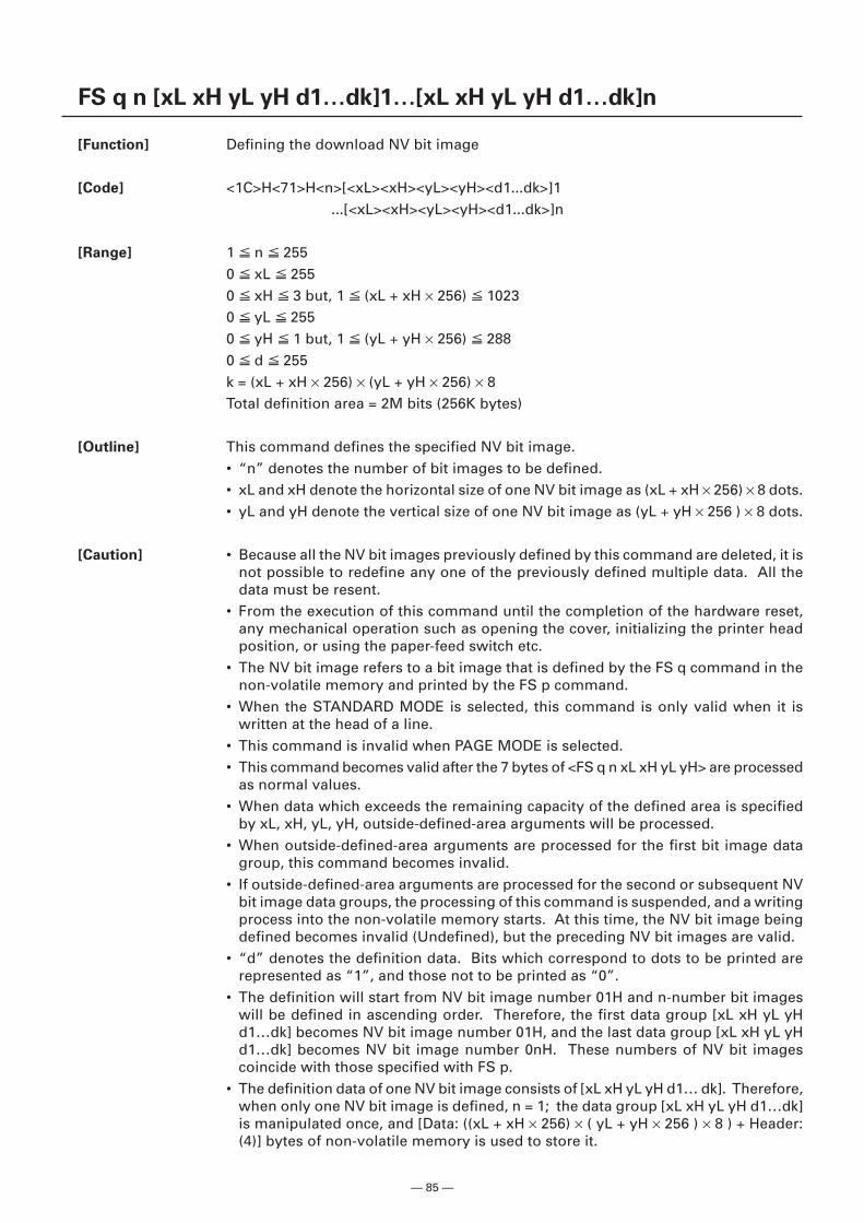
— 85 —
FS q n [xL xH yL yH d1…dk]1…[xL xH yL yH d1…dk]n
[Function] Defining the download NV bit image
[Code] <1C>H<71>H<n>[<xL><xH><yL><yH><d1...dk>]1 ...[<xL><xH><yL><yH><d1...dk>]n
[Range] 1 n 2550 xL 2550 xH 3 but, 1 (xL + xH × 256) 10230 yL 2550 yH 1 but, 1 (yL + yH × 256) 2880 d 255k = (xL + xH × 256) × (yL + yH × 256) × 8Total definition area = 2M bits (256K bytes)
[Outline] This command defines the specified NV bit image.• “n” denotes the number of bit images to be defined.• xL and xH denote the horizontal size of one NV bit image as (xL + xH × 256) × 8 dots.• yL and yH denote the vertical size of one NV bit image as (yL + yH × 256 ) × 8 dots.
[Caution] • Because all the NV bit images previously defined by this command are deleted, it isnot possible to redefine any one of the previously defined multiple data. All thedata must be resent.
• From the execution of this command until the completion of the hardware reset,any mechanical operation such as opening the cover, initializing the printer headposition, or using the paper-feed switch etc.
• The NV bit image refers to a bit image that is defined by the FS q command in thenon-volatile memory and printed by the FS p command.
• When the STANDARD MODE is selected, this command is only valid when it iswritten at the head of a line.
• This command is invalid when PAGE MODE is selected.• This command becomes valid after the 7 bytes of <FS q n xL xH yL yH> are processed
as normal values.• When data which exceeds the remaining capacity of the defined area is specified
by xL, xH, yL, yH, outside-defined-area arguments will be processed.• When outside-defined-area arguments are processed for the first bit image data
group, this command becomes invalid.• If outside-defined-area arguments are processed for the second or subsequent NV
bit image data groups, the processing of this command is suspended, and a writingprocess into the non-volatile memory starts. At this time, the NV bit image beingdefined becomes invalid (Undefined), but the preceding NV bit images are valid.
• “d” denotes the definition data. Bits which correspond to dots to be printed arerepresented as “1”, and those not to be printed as “0”.
• The definition will start from NV bit image number 01H and n-number bit imageswill be defined in ascending order. Therefore, the first data group [xL xH yL yHd1…dk] becomes NV bit image number 01H, and the last data group [xL xH yL yHd1…dk] becomes NV bit image number 0nH. These numbers of NV bit imagescoincide with those specified with FS p.
• The definition data of one NV bit image consists of [xL xH yL yH d1… dk]. Therefore,when only one NV bit image is defined, n = 1; the data group [xL xH yL yH d1…dk]is manipulated once, and [Data: ((xL + xH × 256) × ( yL + yH × 256 ) × 8 ) + Header:(4)] bytes of non-volatile memory is used to store it.
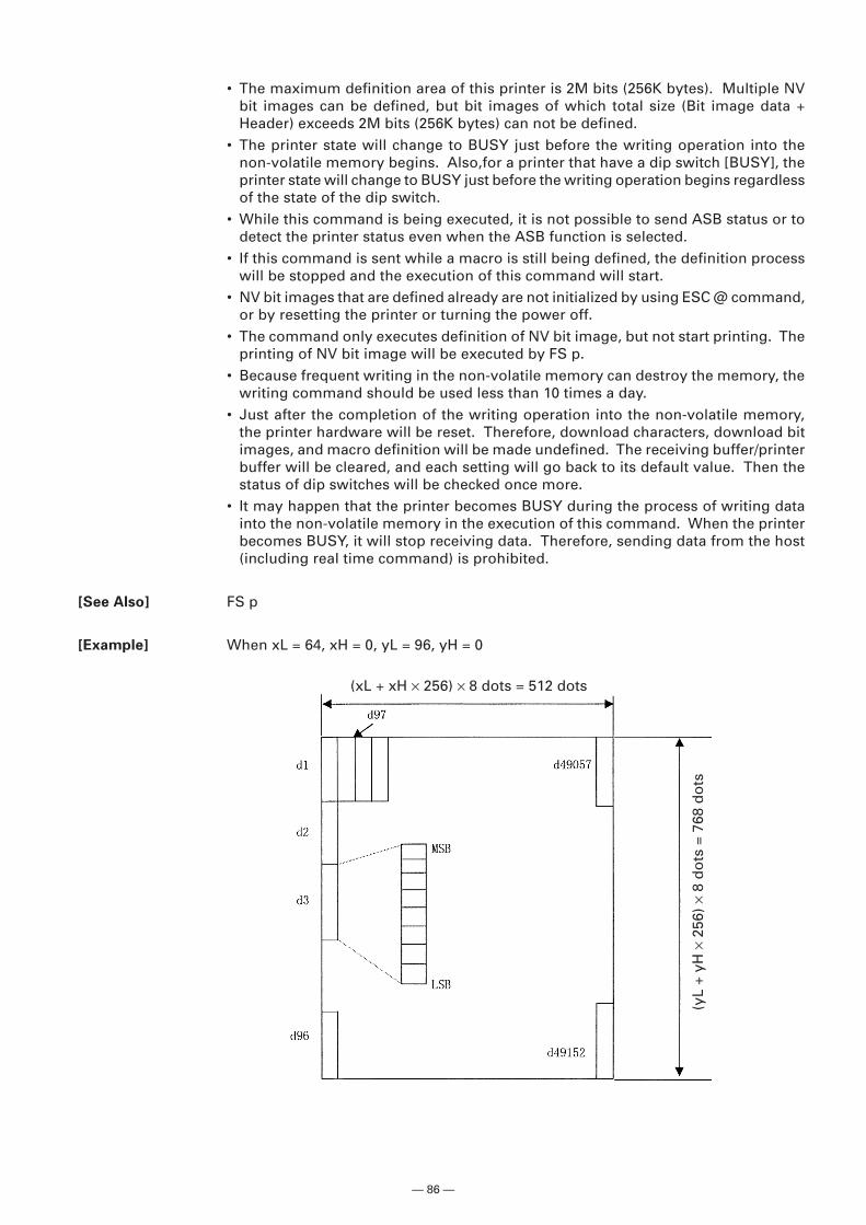
— 86 —
• The maximum definition area of this printer is 2M bits (256K bytes). Multiple NVbit images can be defined, but bit images of which total size (Bit image data +Header) exceeds 2M bits (256K bytes) can not be defined.
• The printer state will change to BUSY just before the writing operation into thenon-volatile memory begins. Also,for a printer that have a dip switch [BUSY], theprinter state will change to BUSY just before the writing operation begins regardlessof the state of the dip switch.
• While this command is being executed, it is not possible to send ASB status or todetect the printer status even when the ASB function is selected.
• If this command is sent while a macro is still being defined, the definition processwill be stopped and the execution of this command will start.
• NV bit images that are defined already are not initialized by using ESC @ command,or by resetting the printer or turning the power off.
• The command only executes definition of NV bit image, but not start printing. Theprinting of NV bit image will be executed by FS p.
• Because frequent writing in the non-volatile memory can destroy the memory, thewriting command should be used less than 10 times a day.
• Just after the completion of the writing operation into the non-volatile memory,the printer hardware will be reset. Therefore, download characters, download bitimages, and macro definition will be made undefined. The receiving buffer/printerbuffer will be cleared, and each setting will go back to its default value. Then thestatus of dip switches will be checked once more.
• It may happen that the printer becomes BUSY during the process of writing datainto the non-volatile memory in the execution of this command. When the printerbecomes BUSY, it will stop receiving data. Therefore, sending data from the host(including real time command) is prohibited.
[See Also] FS p
[Example] When xL = 64, xH = 0, yL = 96, yH = 0
(yL
+ yH
× 2
56)
× 8
do
ts =
768
do
ts(xL + xH × 256) × 8 dots = 512 dots
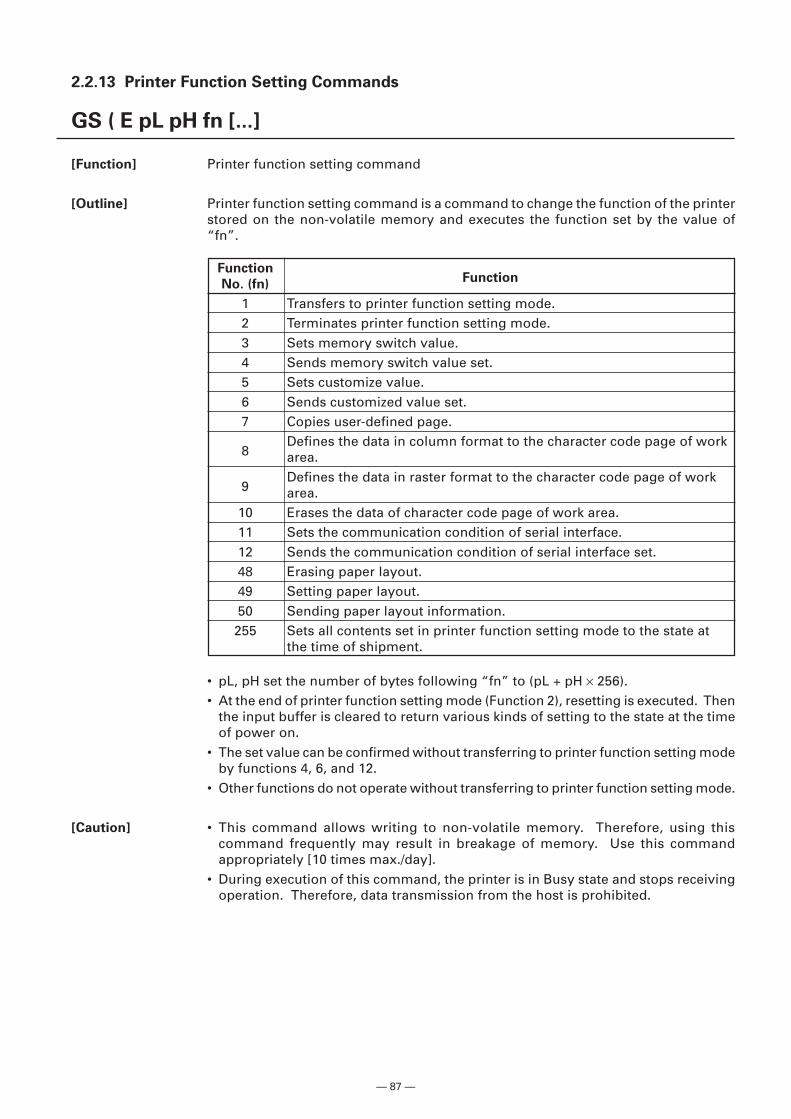
— 87 —
2.2.13 Printer Function Setting Commands
GS ( E pL pH fn [...]
[Function] Printer function setting command
[Outline] Printer function setting command is a command to change the function of the printerstored on the non-volatile memory and executes the function set by the value of“fn”.
• pL, pH set the number of bytes following “fn” to (pL + pH × 256).• At the end of printer function setting mode (Function 2), resetting is executed. Then
the input buffer is cleared to return various kinds of setting to the state at the timeof power on.
• The set value can be confirmed without transferring to printer function setting modeby functions 4, 6, and 12.
• Other functions do not operate without transferring to printer function setting mode.
[Caution] • This command allows writing to non-volatile memory. Therefore, using thiscommand frequently may result in breakage of memory. Use this commandappropriately [10 times max./day].
• During execution of this command, the printer is in Busy state and stops receivingoperation. Therefore, data transmission from the host is prohibited.
FunctionFunction
No. (fn)
1 Transfers to printer function setting mode.2 Terminates printer function setting mode.3 Sets memory switch value.4 Sends memory switch value set.5 Sets customize value.6 Sends customized value set.7 Copies user-defined page.
8Defines the data in column format to the character code page of workarea.
9Defines the data in raster format to the character code page of workarea.
10 Erases the data of character code page of work area.11 Sets the communication condition of serial interface.12 Sends the communication condition of serial interface set.48 Erasing paper layout.49 Setting paper layout.50 Sending paper layout information.255 Sets all contents set in printer function setting mode to the state at
the time of shipment.
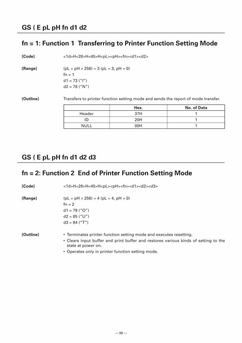
— 88 —
GS ( E pL pH fn d1 d2
fn = 1: Function 1 Transferring to Printer Function Setting Mode
[Code] <1d>H<28>H<45>H<pL><pH><fn><d1><d2>
[Range] (pL + pH × 256) = 3 (pL = 3, pH = 0)fn = 1d1 = 73 (“I”)d2 = 78 (“N”)
[Outline] Transfers to printer function setting mode and sends the report of mode transfer.
Hex. No. of Data
Header 37H 1ID 20H 1
NULL 00H 1
GS ( E pL pH fn d1 d2 d3
fn = 2: Function 2 End of Printer Function Setting Mode
[Code] <1d>H<28>H<45>H<pL><pH><fn><d1><d2><d3>
[Range] (pL + pH × 256) = 4 (pL = 4, pH = 0)fn = 2d1 = 79 (“O”)d2 = 85 (“U”)d3 = 84 (“T”)
[Outline] • Terminates printer function setting mode and executes resetting.• Clears input buffer and print buffer and restores various kinds of setting to the
state at power on.• Operates only in printer function setting mode.
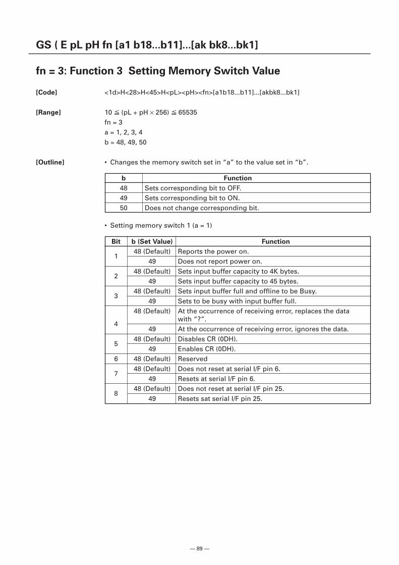
— 89 —
GS ( E pL pH fn [a1 b18...b11]...[ak bk8...bk1]
fn = 3: Function 3 Setting Memory Switch Value
[Code] <1d>H<28>H<45>H<pL><pH><fn>[a1b18...b11]...[akbk8...bk1]
[Range] 10 (pL + pH × 256) 65535fn = 3a = 1, 2, 3, 4b = 48, 49, 50
[Outline] • Changes the memory switch set in “a” to the value set in “b”.
b Function
48 Sets corresponding bit to OFF.49 Sets corresponding bit to ON.50 Does not change corresponding bit.
Bit b (Set Value) Function
148 (Default) Reports the power on.
49 Does not report power on.
248 (Default) Sets input buffer capacity to 4K bytes.
49 Sets input buffer capacity to 45 bytes.
348 (Default) Sets input buffer full and offline to be Busy.
49 Sets to be busy with input buffer full.48 (Default) At the occurrence of receiving error, replaces the data
4with “?”.
49 At the occurrence of receiving error, ignores the data.
548 (Default) Disables CR (0DH).
49 Enables CR (0DH).6 48 (Default) Reserved
748 (Default) Does not reset at serial I/F pin 6.
49 Resets at serial I/F pin 6.
848 (Default) Does not reset at serial I/F pin 25.
49 Resets sat serial I/F pin 25.
• Setting memory switch 1 (a = 1)
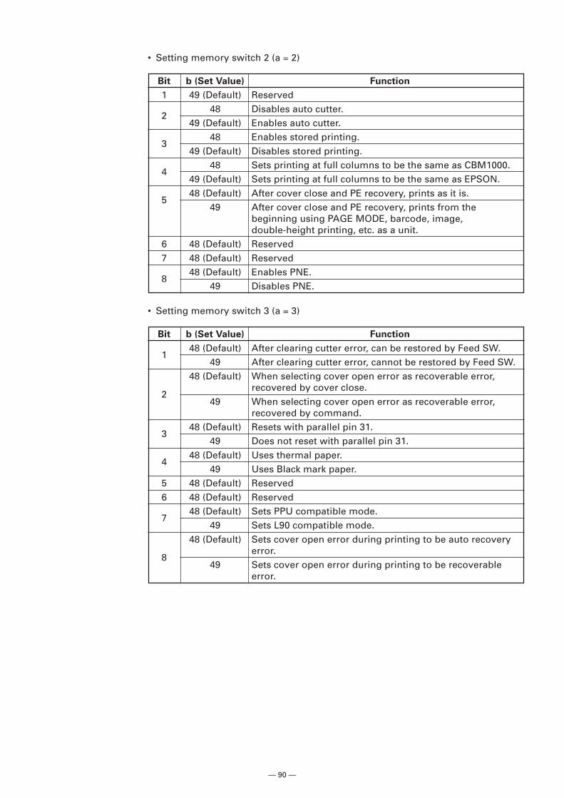
— 90 —
• Setting memory switch 2 (a = 2)
Bit b (Set Value) Function
1 49 (Default) Reserved
248 Disables auto cutter.
49 (Default) Enables auto cutter.
348 Enables stored printing.
49 (Default) Disables stored printing.
448 Sets printing at full columns to be the same as CBM1000.
49 (Default) Sets printing at full columns to be the same as EPSON.
548 (Default) After cover close and PE recovery, prints as it is.
49 After cover close and PE recovery, prints from thebeginning using PAGE MODE, barcode, image,double-height printing, etc. as a unit.
6 48 (Default) Reserved7 48 (Default) Reserved
848 (Default) Enables PNE.
49 Disables PNE.
• Setting memory switch 3 (a = 3)
Bit b (Set Value) Function
148 (Default) After clearing cutter error, can be restored by Feed SW.
49 After clearing cutter error, cannot be restored by Feed SW.48 (Default) When selecting cover open error as recoverable error,
2recovered by cover close.
49 When selecting cover open error as recoverable error,recovered by command.
348 (Default) Resets with parallel pin 31.
49 Does not reset with parallel pin 31.
448 (Default) Uses thermal paper.
49 Uses Black mark paper.5 48 (Default) Reserved6 48 (Default) Reserved
748 (Default) Sets PPU compatible mode.
49 Sets L90 compatible mode.48 (Default) Sets cover open error during printing to be auto recovery
8error.
49 Sets cover open error during printing to be recoverableerror.
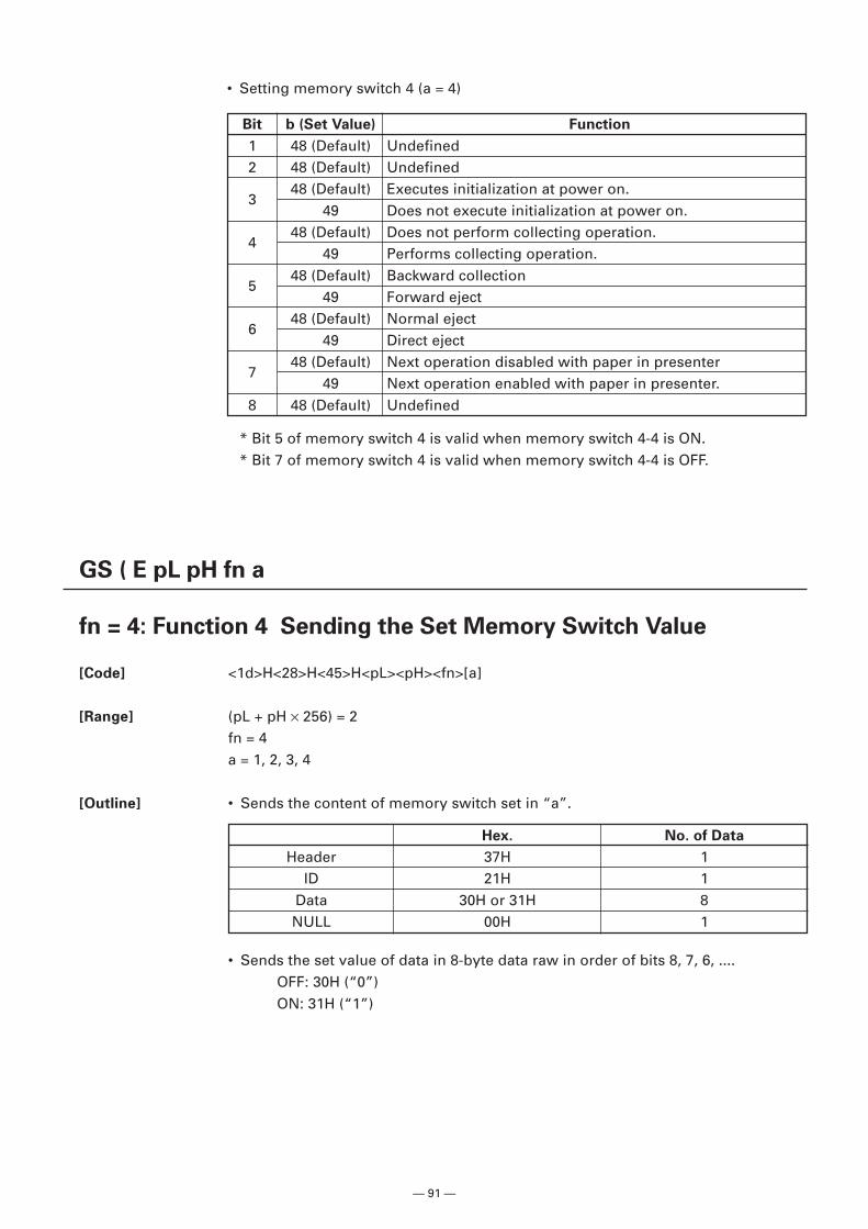
— 91 —
• Setting memory switch 4 (a = 4)
Bit b (Set Value) Function
1 48 (Default) Undefined2 48 (Default) Undefined
348 (Default) Executes initialization at power on.
49 Does not execute initialization at power on.
448 (Default) Does not perform collecting operation.
49 Performs collecting operation.
548 (Default) Backward collection
49 Forward eject
648 (Default) Normal eject
49 Direct eject
748 (Default) Next operation disabled with paper in presenter
49 Next operation enabled with paper in presenter.8 48 (Default) Undefined
* Bit 5 of memory switch 4 is valid when memory switch 4-4 is ON.* Bit 7 of memory switch 4 is valid when memory switch 4-4 is OFF.
GS ( E pL pH fn a
fn = 4: Function 4 Sending the Set Memory Switch Value
[Code] <1d>H<28>H<45>H<pL><pH><fn>[a]
[Range] (pL + pH × 256) = 2fn = 4a = 1, 2, 3, 4
[Outline] • Sends the content of memory switch set in “a”.
• Sends the set value of data in 8-byte data raw in order of bits 8, 7, 6, .... OFF: 30H (“0”) ON: 31H (“1”)
Hex. No. of Data
Header 37H 1ID 21H 1
Data 30H or 31H 8NULL 00H 1
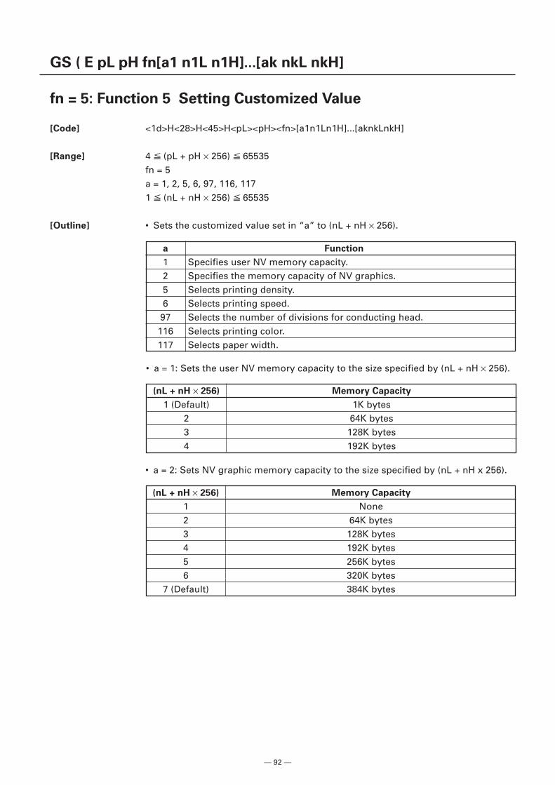
— 92 —
GS ( E pL pH fn[a1 n1L n1H]...[ak nkL nkH]
fn = 5: Function 5 Setting Customized Value
[Code] <1d>H<28>H<45>H<pL><pH><fn>[a1n1Ln1H]...[aknkLnkH]
[Range] 4 (pL + pH × 256) 65535fn = 5a = 1, 2, 5, 6, 97, 116, 1171 (nL + nH × 256) 65535
[Outline] • Sets the customized value set in “a” to (nL + nH × 256).
a Function
1 Specifies user NV memory capacity.2 Specifies the memory capacity of NV graphics.5 Selects printing density.6 Selects printing speed.97 Selects the number of divisions for conducting head.
116 Selects printing color.117 Selects paper width.
• a = 1: Sets the user NV memory capacity to the size specified by (nL + nH × 256).
(nL + nH × 256) Memory Capacity
1 (Default) 1K bytes2 64K bytes3 128K bytes4 192K bytes
• a = 2: Sets NV graphic memory capacity to the size specified by (nL + nH x 256).
(nL + nH × 256) Memory Capacity
1 None2 64K bytes3 128K bytes4 192K bytes5 256K bytes6 320K bytes
7 (Default) 384K bytes
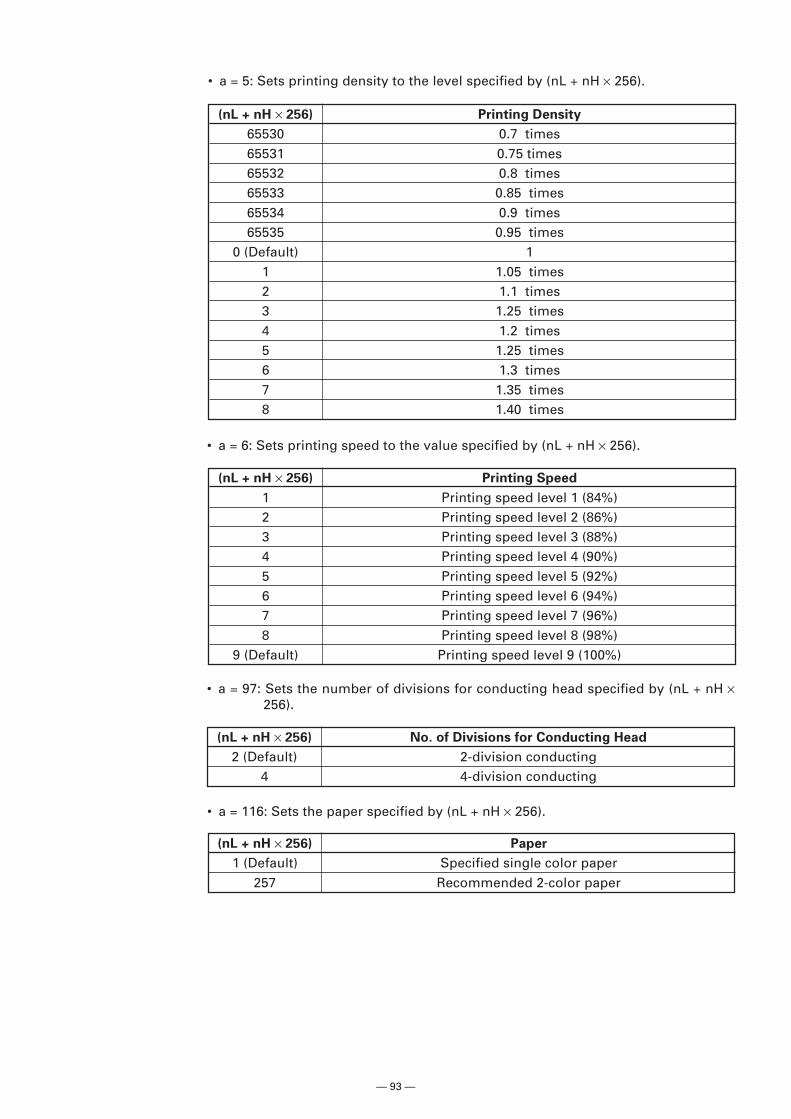
— 93 —
• a = 5: Sets printing density to the level specified by (nL + nH × 256).
(nL + nH × 256) Printing Density
65530 0.7 times65531 0.75 times65532 0.8 times65533 0.85 times65534 0.9 times65535 0.95 times
0 (Default) 11 1.05 times2 1.1 times3 1.25 times4 1.2 times5 1.25 times6 1.3 times7 1.35 times8 1.40 times
(nL + nH × 256) Printing Speed
1 Printing speed level 1 (84%)2 Printing speed level 2 (86%)3 Printing speed level 3 (88%)4 Printing speed level 4 (90%)5 Printing speed level 5 (92%)6 Printing speed level 6 (94%)7 Printing speed level 7 (96%)8 Printing speed level 8 (98%)
9 (Default) Printing speed level 9 (100%)
• a = 97: Sets the number of divisions for conducting head specified by (nL + nH ×256).
(nL + nH × 256) No. of Divisions for Conducting Head
2 (Default) 2-division conducting4 4-division conducting
• a = 6: Sets printing speed to the value specified by (nL + nH × 256).
• a = 116: Sets the paper specified by (nL + nH × 256).
(nL + nH × 256) Paper
1 (Default) Specified single color paper257 Recommended 2-color paper
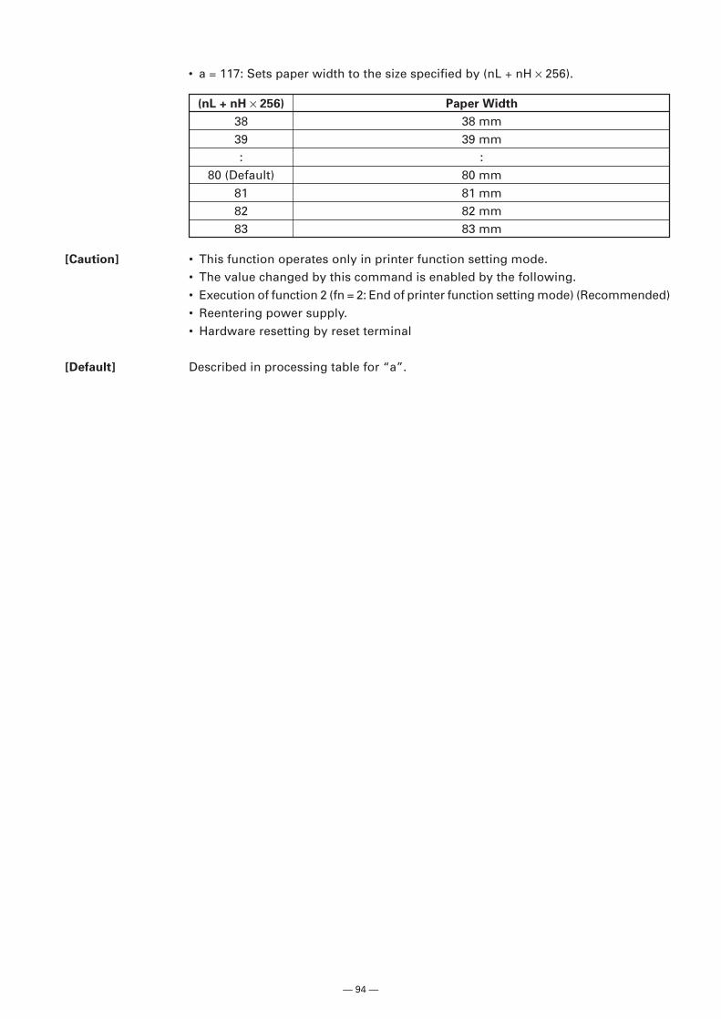
— 94 —
• a = 117: Sets paper width to the size specified by (nL + nH × 256).
(nL + nH × 256) Paper Width
38 38 mm39 39 mm: :
80 (Default) 80 mm81 81 mm82 82 mm83 83 mm
[Caution] • This function operates only in printer function setting mode.• The value changed by this command is enabled by the following.• Execution of function 2 (fn = 2: End of printer function setting mode) (Recommended)• Reentering power supply.• Hardware resetting by reset terminal
[Default] Described in processing table for “a”.
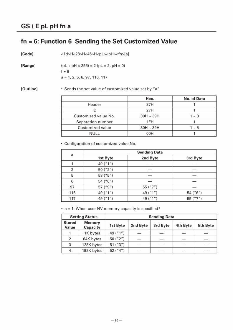
— 95 —
GS ( E pL pH fn a
fn = 6: Function 6 Sending the Set Customized Value
[Code] <1d>H<28>H<45>H<pL><pH><fn>[a]
[Range] (pL + pH × 256) = 2 (pL = 2, pH = 0)f = 6a = 1, 2, 5, 6, 97, 116, 117
[Outline] • Sends the set value of customized value set by “a”.
Hex. No. of Data
Header 37H 1ID 27H 1
Customized value No. 30H ~ 39H 1 ~ 3Separation number 1FH 1Customized value 30H ~ 39H 1 ~ 5
NULL 00H 1
aSending Data
1st Byte 2nd Byte 3rd Byte
1 49 (“1”) — —2 50 (“2”) — —5 53 (“5”) — —6 54 (“6”) — —97 57 (“9”) 55 (“7”) —116 49 (“1”) 49 (“1”) 54 (“6”)117 49 (“1”) 49 (“1”) 55 (“7”)
Setting Status Sending Data
Stored Memory1st Byte 2nd Byte 3rd Byte 4th Byte 5th Byte
Value Capacity
1 1K bytes 49 (“1”) — — — —2 64K bytes 50 (“2”) — — — —3 128K bytes 51 (“3”) — — — —4 192K bytes 52 (“4”) — — — —
• a = 1: When user NV memory capacity is specified*
• Configuration of customized value No.
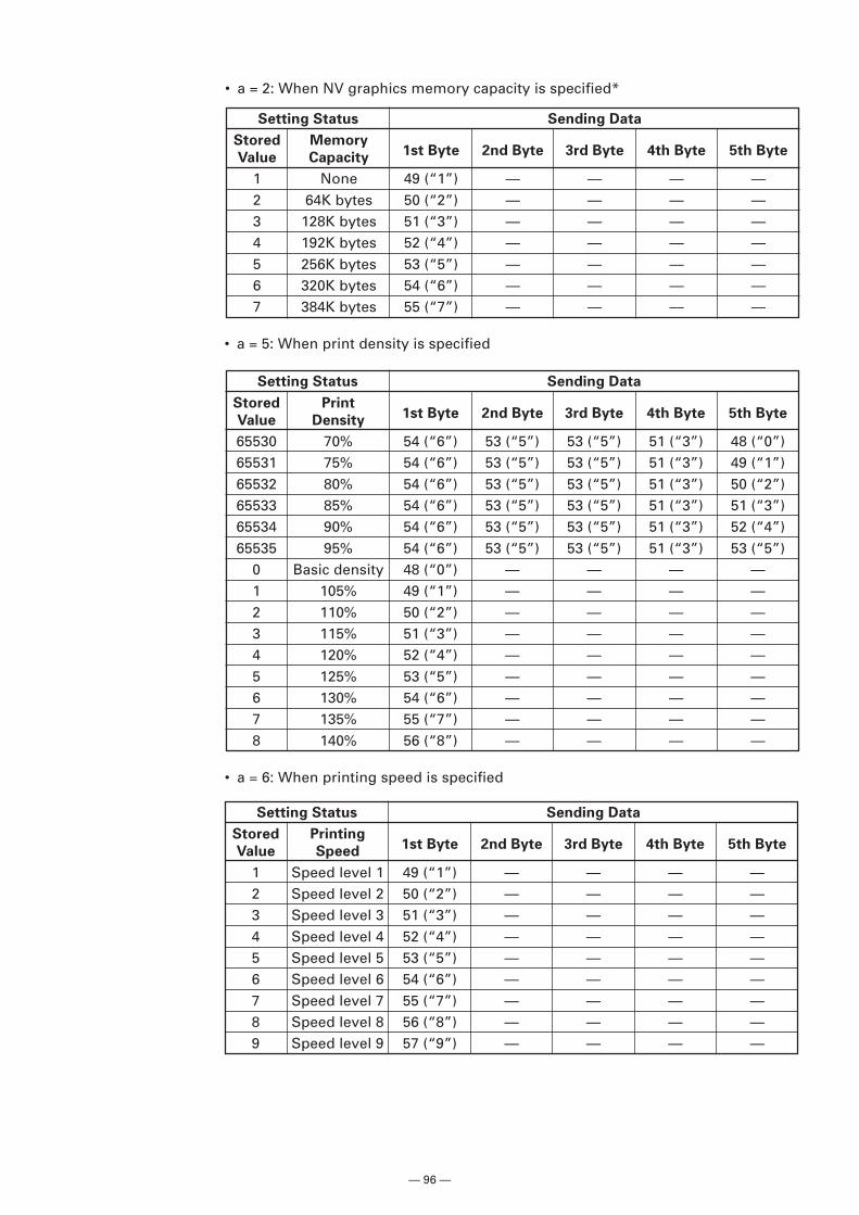
— 96 —
• a = 5: When print density is specified
Setting Status Sending Data
Stored Print1st Byte 2nd Byte 3rd Byte 4th Byte 5th Byte
Value Density
65530 70% 54 (“6”) 53 (“5”) 53 (“5”) 51 (“3”) 48 (“0”)65531 75% 54 (“6”) 53 (“5”) 53 (“5”) 51 (“3”) 49 (“1”)65532 80% 54 (“6”) 53 (“5”) 53 (“5”) 51 (“3”) 50 (“2”)65533 85% 54 (“6”) 53 (“5”) 53 (“5”) 51 (“3”) 51 (“3”)65534 90% 54 (“6”) 53 (“5”) 53 (“5”) 51 (“3”) 52 (“4”)65535 95% 54 (“6”) 53 (“5”) 53 (“5”) 51 (“3”) 53 (“5”)
0 Basic density 48 (“0”) — — — —1 105% 49 (“1”) — — — —2 110% 50 (“2”) — — — —3 115% 51 (“3”) — — — —4 120% 52 (“4”) — — — —5 125% 53 (“5”) — — — —6 130% 54 (“6”) — — — —7 135% 55 (“7”) — — — —8 140% 56 (“8”) — — — —
Setting Status Sending Data
Stored Memory1st Byte 2nd Byte 3rd Byte 4th Byte 5th Byte
Value Capacity
1 None 49 (“1”) — — — —2 64K bytes 50 (“2”) — — — —3 128K bytes 51 (“3”) — — — —4 192K bytes 52 (“4”) — — — —5 256K bytes 53 (“5”) — — — —6 320K bytes 54 (“6”) — — — —7 384K bytes 55 (“7”) — — — —
• a = 2: When NV graphics memory capacity is specified*
• a = 6: When printing speed is specified
Setting Status Sending Data
Stored Printing1st Byte 2nd Byte 3rd Byte 4th Byte 5th Byte
Value Speed
1 Speed level 1 49 (“1”) — — — —2 Speed level 2 50 (“2”) — — — —3 Speed level 3 51 (“3”) — — — —4 Speed level 4 52 (“4”) — — — —5 Speed level 5 53 (“5”) — — — —6 Speed level 6 54 (“6”) — — — —7 Speed level 7 55 (“7”) — — — —8 Speed level 8 56 (“8”) — — — —9 Speed level 9 57 (“9”) — — — —
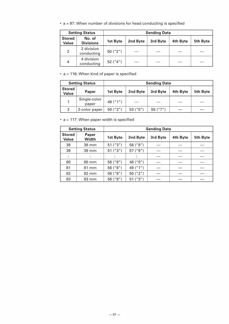
— 97 —
• a = 97: When number of divisions for head conducting is specified
Setting Status Sending Data
Stored No. of1st Byte 2nd Byte 3rd Byte 4th Byte 5th Byte
Value Divisions
22 division
50 (“2”) — — — —conducting
44 division
52 (“4”) — — — —conducting
• a = 116: When kind of paper is specified
Setting Status Sending Data
StoredPaper 1st Byte 2nd Byte 3rd Byte 4th Byte 5th Byte
Value
1Single-color
49 (“1”) — — — —paper2 2-color paper 50 (“2”) 53 (“5”) 55 (“7”) — —
• a = 117: When paper width is specified
Setting Status Sending Data
Stored Paper1st Byte 2nd Byte 3rd Byte 4th Byte 5th Byte
Value Width
38 38 mm 51 (“3”) 56 (“8”) — — —39 39 mm 51 (“3”) 57 (“9”) — — —: : : : — — —
80 80 mm 56 (“8”) 48 (“0”) — — —81 81 mm 56 (“8”) 49 (“1”) — — —82 82 mm 56 (“8”) 50 (“2”) — — —83 83 mm 56 (“8”) 51 (“3”) — — —
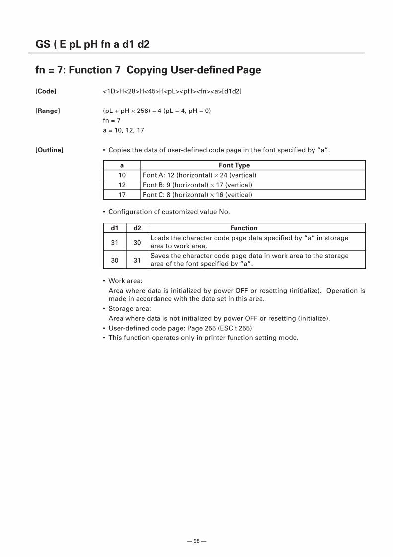
— 98 —
GS ( E pL pH fn a d1 d2
fn = 7: Function 7 Copying User-defined Page
[Code] <1D>H<28>H<45>H<pL><pH><fn><a>[d1d2]
[Range] (pL + pH × 256) = 4 (pL = 4, pH = 0)fn = 7a = 10, 12, 17
[Outline] • Copies the data of user-defined code page in the font specified by “a”.
a Font Type
10 Font A: 12 (horizontal) × 24 (vertical)12 Font B: 9 (horizontal) × 17 (vertical)17 Font C: 8 (horizontal) × 16 (vertical)
• Configuration of customized value No.
• Work area:Area where data is initialized by power OFF or resetting (initialize). Operation ismade in accordance with the data set in this area.
• Storage area:Area where data is not initialized by power OFF or resetting (initialize).
• User-defined code page: Page 255 (ESC t 255)• This function operates only in printer function setting mode.
d1 d2 Function
31 30Loads the character code page data specified by “a” in storagearea to work area.
30 31Saves the character code page data in work area to the storagearea of the font specified by “a”.
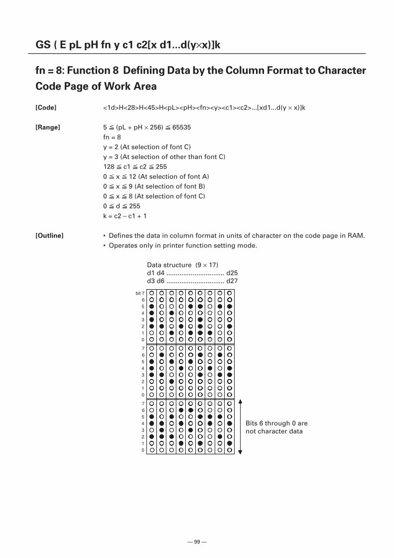
— 99 —
GS ( E pL pH fn y c1 c2[x d1...d(y×x)]k
fn = 8: Function 8 Defining Data by the Column Format to Character
Code Page of Work Area
[Code] <1d>H<28>H<45>H<pL><pH><fn><y><c1><c2>...[xd1...d(y × x)]k
[Range] 5 (pL + pH × 256) 65535fn = 8y = 2 (At selection of font C)y = 3 (At selection of other than font C)128 c1 c2 2550 x 12 (At selection of font A)0 x 9 (At selection of font B)0 x 8 (At selection of font C)0 d 255k = c2 – c1 + 1
[Outline] • Defines the data in column format in units of character on the code page in RAM.• Operates only in printer function setting mode.
Data structure (9 × 17)d1 d4 ............................... d25d3 d6 ............................... d27
Bits 6 through 0 arenot character data
bit 76543210
76543210
76543210
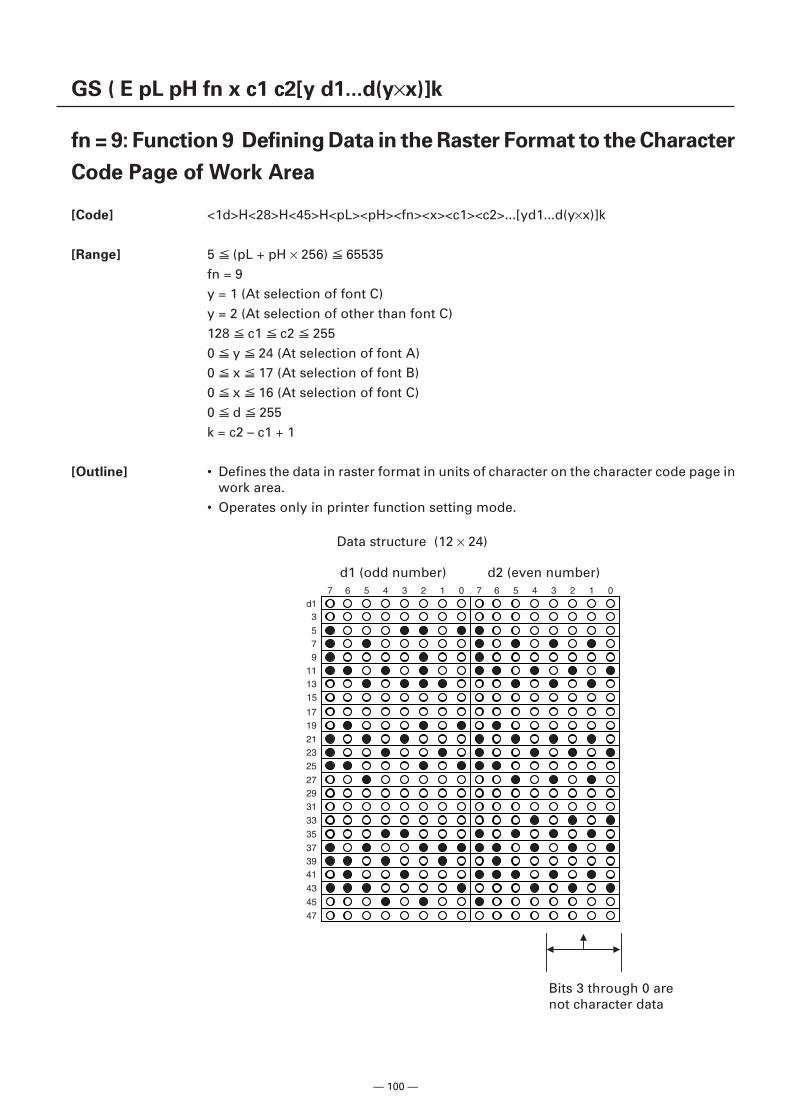
— 100 —
GS ( E pL pH fn x c1 c2[y d1...d(y×x)]k
fn = 9: Function 9 Defining Data in the Raster Format to the Character
Code Page of Work Area
[Code] <1d>H<28>H<45>H<pL><pH><fn><x><c1><c2>...[yd1...d(y×x)]k
[Range] 5 (pL + pH × 256) 65535fn = 9y = 1 (At selection of font C)y = 2 (At selection of other than font C)128 c1 c2 2550 y 24 (At selection of font A)0 x 17 (At selection of font B)0 x 16 (At selection of font C)0 d 255k = c2 – c1 + 1
[Outline] • Defines the data in raster format in units of character on the character code page inwork area.
• Operates only in printer function setting mode.
Data structure (12 × 24)
d1 (odd number) d2 (even number)
Bits 3 through 0 arenot character data
d13
579
1113
15
1719
2123
25
272931
33
35
373941
43
45
47
7 6 5 4 3 2 1 0 7 6 5 4 3 2 1 0
— 101 —
GS ( E pL pH fn c1 c2
fn = 10: Function 10 Erasing Data of Character Code Page Data in
Work Area
[Code] <1d>H<28>H<45>H<pL><pH><fn><c1><c2>
[Range] (pL + pH × 256) = 3fn = 10128 c1 c2 255
[Outline] • Erases (set to space) data in units of character on the character code page in workarea.
• Operates only in printer function setting mode.
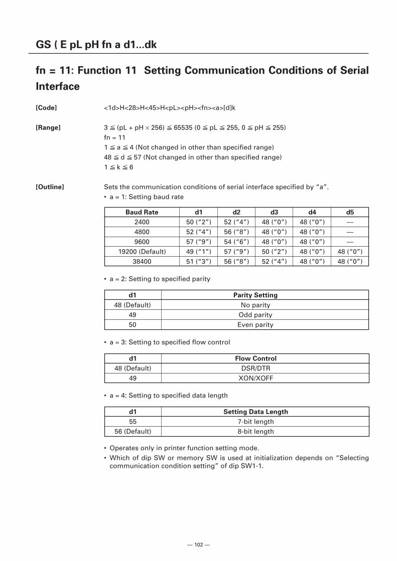
— 102 —
GS ( E pL pH fn a d1...dk
fn = 11: Function 11 Setting Communication Conditions of Serial
Interface
[Code] <1d>H<28>H<45>H<pL><pH><fn><a>[d]k
[Range] 3 (pL + pH × 256) 65535 (0 pL 255, 0 pH 255)fn = 111 a 4 (Not changed in other than specified range)48 d 57 (Not changed in other than specified range)1 k 6
[Outline] Sets the communication conditions of serial interface specified by “a”.• a = 1: Setting baud rate
Baud Rate d1 d2 d3 d4 d5
2400 50 (“2”) 52 (“4”) 48 (“0”) 48 (“0”) —4800 52 (“4”) 56 (“8”) 48 (“0”) 48 (“0”) —9600 57 (“9”) 54 (“6”) 48 (“0”) 48 (“0”) —
19200 (Default) 49 (“1”) 57 (“9”) 50 (“2”) 48 (“0”) 48 (“0”)38400 51 (“3”) 56 (“8”) 52 (“4”) 48 (“0”) 48 (“0”)
• Operates only in printer function setting mode.• Which of dip SW or memory SW is used at initialization depends on “Selecting
communication condition setting” of dip SW1-1.
• a = 2: Setting to specified parity
d1 Parity Setting
48 (Default) No parity49 Odd parity50 Even parity
d1 Flow Control
48 (Default) DSR/DTR49 XON/XOFF
• a = 3: Setting to specified flow control
d1 Setting Data Length
55 7-bit length56 (Default) 8-bit length
• a = 4: Setting to specified data length
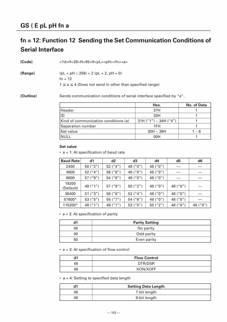
— 103 —
GS ( E pL pH fn a
fn = 12: Function 12 Sending the Set Communication Conditions of
Serial Interface
[Code] <1d>H<28>H<45>H<pL><pH><fn><a>
[Range] (pL + pH × 256) = 2 (pL = 2, pH = 0)fn = 121 a 4 (Does not send in other than specified range)
[Outline] Sends communication conditions of serial interface specified by “a”.
Hex. No. of Data
Header 37H 1ID 33H 1Kind of communication conditions (a) 31H (“1”) ~ 34H (“4”) 1Separation number 1FH 1Set value 30H ~ 39H 1 ~ 6NULL 00H 1
Set value
• a = 1: At specification of baud rate
Baud Rate d1 d2 d3 d4 d5 d6
2400 50 (“2”) 52 (“4”) 48 (“0”) 48 (“0”) — —4800 52 (“4”) 56 (“8”) 48 (“0”) 48 (“0”) — —9600 57 (“9”) 54 (“6”) 48 (“0”) 48 (“0”) — —
1920049 (“1”) 57 (“9”) 50 (“2”) 48 (“0”) 48 (“0”) —(Default)
38400 51 (“3”) 56 (“8”) 52 (“4”) 48 (“0”) 48 (“0”) —57600* 53 (“5”) 55 (“7”) 54 (“6”) 48 (“0”) 48 (“0”) —115200* 49 (“1”) 49 (“1”) 53 (“5”) 50 (“2”) 48 (“0”) 48 (“0”)
• a = 2: At specification of parity
d1 Parity Setting
48 No parity49 Odd parity50 Even parity
d1 Flow Control
48 DTR/DSR49 XON/XOFF
• a = 3: At specification of flow control
d1 Setting Data Length
48 7-bit length49 8-bit length
• a = 4: Setting to specified data length
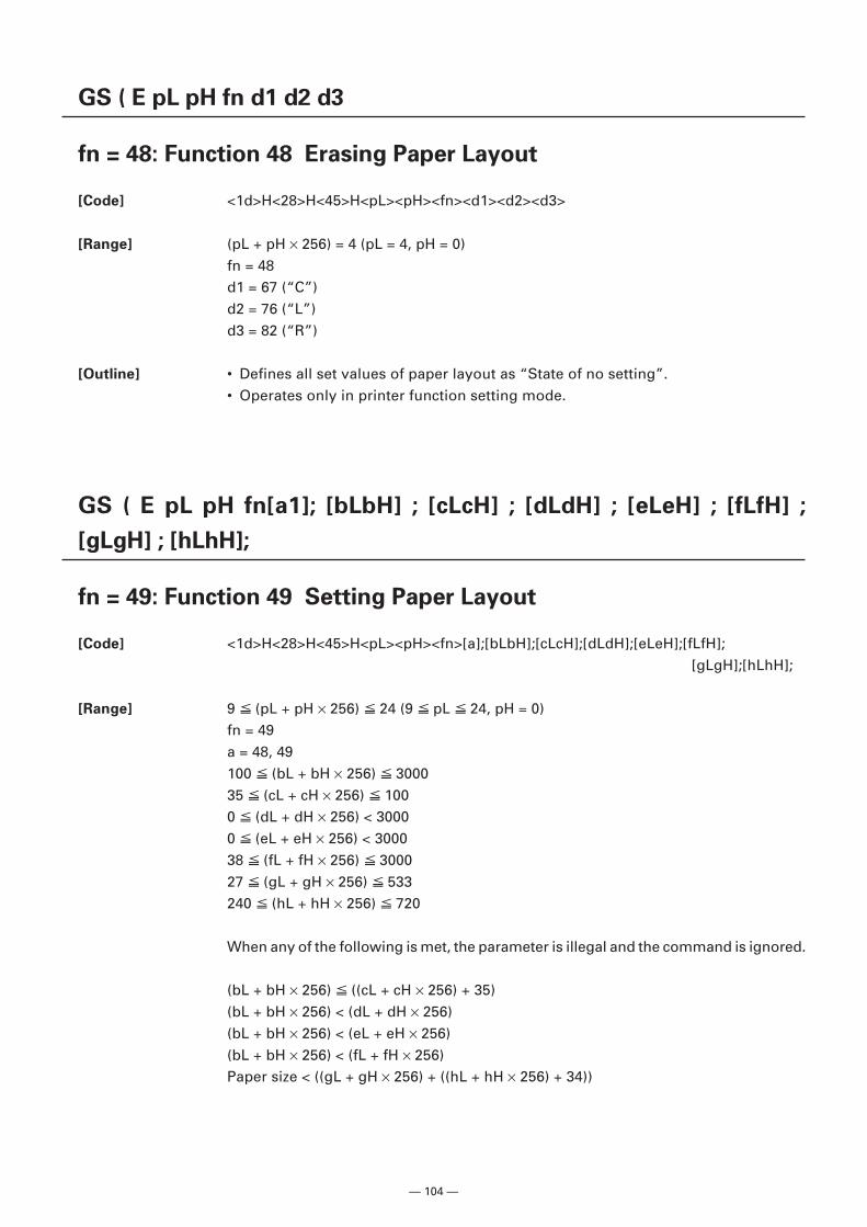
— 104 —
GS ( E pL pH fn d1 d2 d3
fn = 48: Function 48 Erasing Paper Layout
[Code] <1d>H<28>H<45>H<pL><pH><fn><d1><d2><d3>
[Range] (pL + pH × 256) = 4 (pL = 4, pH = 0)fn = 48d1 = 67 (“C”)d2 = 76 (“L”)d3 = 82 (“R”)
[Outline] • Defines all set values of paper layout as “State of no setting”.• Operates only in printer function setting mode.
GS ( E pL pH fn[a1]; [bLbH] ; [cLcH] ; [dLdH] ; [eLeH] ; [fLfH] ;
[gLgH] ; [hLhH];
fn = 49: Function 49 Setting Paper Layout
[Code] <1d>H<28>H<45>H<pL><pH><fn>[a];[bLbH];[cLcH];[dLdH];[eLeH];[fLfH];[gLgH];[hLhH];
[Range] 9 (pL + pH × 256) 24 (9 pL 24, pH = 0)fn = 49a = 48, 49100 (bL + bH × 256) 300035 (cL + cH × 256) 1000 (dL + dH × 256) < 30000 (eL + eH × 256) < 300038 (fL + fH × 256) 300027 (gL + gH × 256) 533240 (hL + hH × 256) 720
When any of the following is met, the parameter is illegal and the command is ignored.
(bL + bH × 256) ((cL + cH × 256) + 35)(bL + bH × 256) < (dL + dH × 256)(bL + bH × 256) < (eL + eH × 256)(bL + bH × 256) < (fL + fH × 256)Paper size < ((gL + gH × 256) + ((hL + hH × 256) + 34))
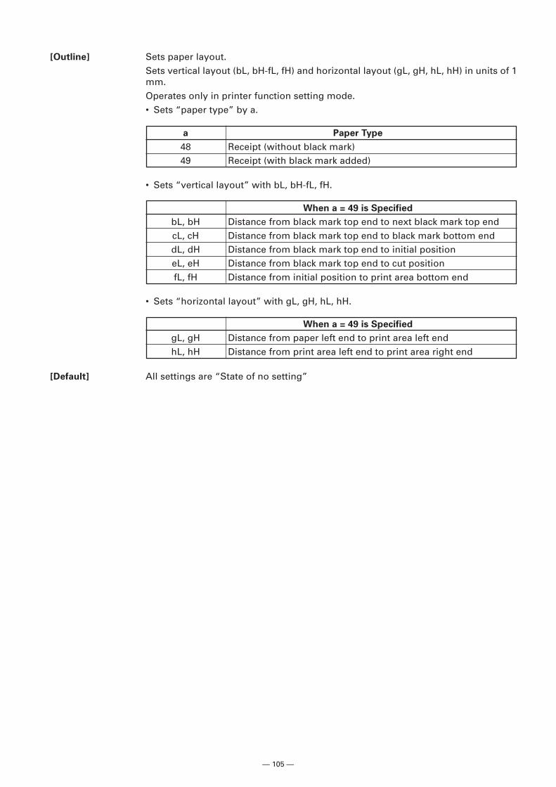
— 105 —
[Outline] Sets paper layout.Sets vertical layout (bL, bH-fL, fH) and horizontal layout (gL, gH, hL, hH) in units of 1mm.Operates only in printer function setting mode.• Sets “paper type” by a.
a Paper Type
48 Receipt (without black mark)49 Receipt (with black mark added)
When a = 49 is Specified
bL, bH Distance from black mark top end to next black mark top endcL, cH Distance from black mark top end to black mark bottom enddL, dH Distance from black mark top end to initial positioneL, eH Distance from black mark top end to cut positionfL, fH Distance from initial position to print area bottom end
• Sets “vertical layout” with bL, bH-fL, fH.
• Sets “horizontal layout” with gL, gH, hL, hH.
[Default] All settings are “State of no setting”
When a = 49 is Specified
gL, gH Distance from paper left end to print area left endhL, hH Distance from print area left end to print area right end
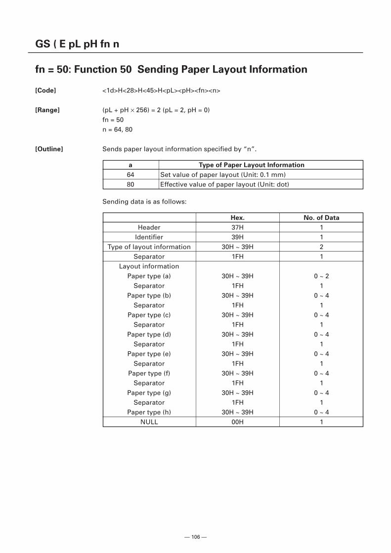
— 106 —
GS ( E pL pH fn n
fn = 50: Function 50 Sending Paper Layout Information
[Code] <1d>H<28>H<45>H<pL><pH><fn><n>
[Range] (pL + pH × 256) = 2 (pL = 2, pH = 0)fn = 50n = 64, 80
[Outline] Sends paper layout information specified by “n”.
a Type of Paper Layout Information
64 Set value of paper layout (Unit: 0.1 mm)80 Effective value of paper layout (Unit: dot)
Sending data is as follows:
Hex. No. of Data
Header 37H 1Identifier 39H 1
Type of layout information 30H ~ 39H 2Separator 1FH 1
Layout informationPaper type (a) 30H ~ 39H 0 ~ 2
Separator 1FH 1Paper type (b) 30H ~ 39H 0 ~ 4
Separator 1FH 1Paper type (c) 30H ~ 39H 0 ~ 4
Separator 1FH 1Paper type (d) 30H ~ 39H 0 ~ 4
Separator 1FH 1Paper type (e) 30H ~ 39H 0 ~ 4
Separator 1FH 1Paper type (f) 30H ~ 39H 0 ~ 4
Separator 1FH 1Paper type (g) 30H ~ 39H 0 ~ 4
Separator 1FH 1Paper type (h) 30H ~ 39H 0 ~ 4
NULL 00H 1
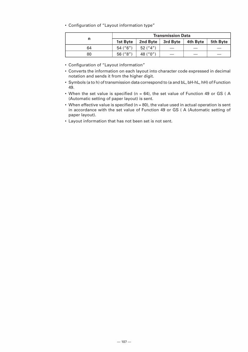
— 107 —
• Configuration of “Layout information”• Converts the information on each layout into character code expressed in decimal
notation and sends it from the higher digit.• Symbols (a to h) of transmission data correspond to (a and bL, bH-hL, hH) of Function
49.• When the set value is specified (n = 64), the set value of Function 49 or GS ( A
(Automatic setting of paper layout) is sent.• When effective value is specified (n = 80), the value used in actual operation is sent
in accordance with the set value of Function 49 or GS ( A (Automatic setting ofpaper layout).
• Layout information that has not been set is not sent.
• Configuration of “Layout information type”
nTransmission Data
1st Byte 2nd Byte 3rd Byte 4th Byte 5th Byte
64 54 (“6”) 52 (“4”) — — —80 56 (“8”) 48 (“0”) — — —
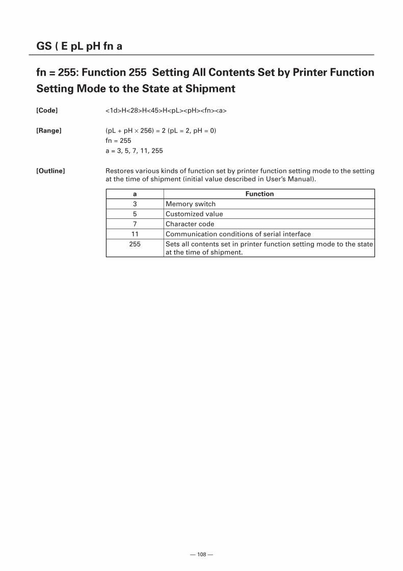
— 108 —
GS ( E pL pH fn a
fn = 255: Function 255 Setting All Contents Set by Printer Function
Setting Mode to the State at Shipment
[Code] <1d>H<28>H<45>H<pL><pH><fn><a>
[Range] (pL + pH × 256) = 2 (pL = 2, pH = 0)fn = 255a = 3, 5, 7, 11, 255
[Outline] Restores various kinds of function set by printer function setting mode to the settingat the time of shipment (initial value described in User’s Manual).
a Function
3 Memory switch5 Customized value7 Character code
11 Communication conditions of serial interface255 Sets all contents set in printer function setting mode to the state
at the time of shipment.
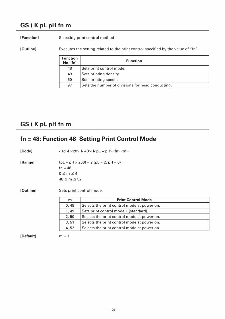
— 109 —
GS ( K pL pH fn m
[Function] Selecting print control method
[Outline] Executes the setting related to the print control specified by the value of “fn”.
FunctionFunction
No. (fn)
48 Sets print control mode.49 Sets printing density.50 Sets printing speed.97 Sets the number of divisions for head conducting.
GS ( K pL pH fn m
fn = 48: Function 48 Setting Print Control Mode
[Code] <1d>H<28>H<4B>H<pL><pH><fn><m>
[Range] (pL + pH × 256) = 2 (pL = 2, pH = 0)fn = 480 m 448 m 52
[Outline] Sets print control mode.
[Default] m = 1
m Print Control Mode
0, 48 Selects the print control mode at power on.1, 49 Sets print control mode 1 (standard)2, 50 Selects the print control mode at power on.3, 51 Selects the print control mode at power on.4, 52 Selects the print control mode at power on.
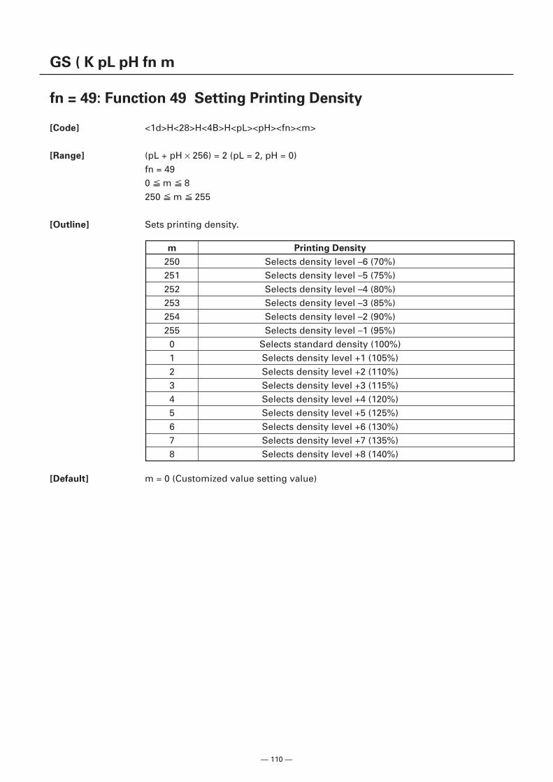
— 110 —
GS ( K pL pH fn m
fn = 49: Function 49 Setting Printing Density
[Code] <1d>H<28>H<4B>H<pL><pH><fn><m>
[Range] (pL + pH × 256) = 2 (pL = 2, pH = 0)fn = 490 m 8250 m 255
[Outline] Sets printing density.
m Printing Density
250 Selects density level –6 (70%)251 Selects density level –5 (75%)252 Selects density level –4 (80%)253 Selects density level –3 (85%)254 Selects density level –2 (90%)255 Selects density level –1 (95%)
0 Selects standard density (100%)1 Selects density level +1 (105%)2 Selects density level +2 (110%)3 Selects density level +3 (115%)4 Selects density level +4 (120%)5 Selects density level +5 (125%)6 Selects density level +6 (130%)7 Selects density level +7 (135%)8 Selects density level +8 (140%)
[Default] m = 0 (Customized value setting value)
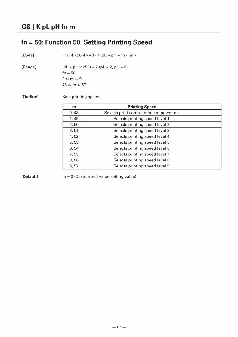
— 111 —
GS ( K pL pH fn m
fn = 50: Function 50 Setting Printing Speed
[Code] <1d>H<28>H<4B>H<pL><pH><fn><m>
[Range] (pL + pH × 256) = 2 (pL = 2, pH = 0)fn = 500 m 948 m 57
[Outline] Sets printing speed.
m Printing Speed
0, 48 Selects print control mode at power on.1, 49 Selects printing speed level 1.2, 50 Selects printing speed level 2.3, 51 Selects printing speed level 3.4, 52 Selects printing speed level 4.5, 53 Selects printing speed level 5.6, 54 Selects printing speed level 6.7, 55 Selects printing speed level 7.8, 56 Selects printing speed level 8.9, 57 Selects printing speed level 9.
[Default] m = 0 (Customized value setting value)
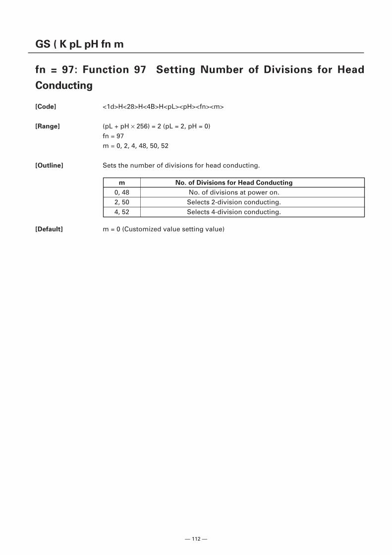
— 112 —
GS ( K pL pH fn m
fn = 97: Function 97 Setting Number of Divisions for Head
Conducting
[Code] <1d>H<28>H<4B>H<pL><pH><fn><m>
[Range] (pL + pH × 256) = 2 (pL = 2, pH = 0)fn = 97m = 0, 2, 4, 48, 50, 52
[Outline] Sets the number of divisions for head conducting.
m No. of Divisions for Head Conducting
0, 48 No. of divisions at power on.2, 50 Selects 2-division conducting.4, 52 Selects 4-division conducting.
[Default] m = 0 (Customized value setting value)
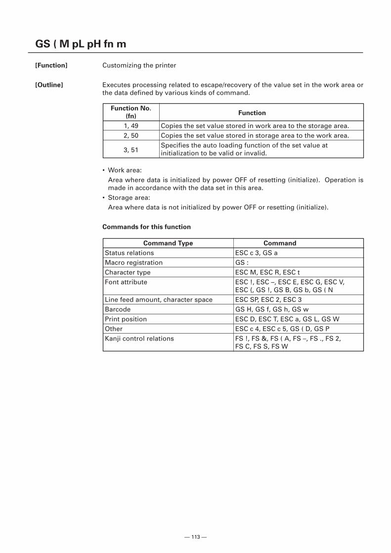
— 113 —
GS ( M pL pH fn m
[Function] Customizing the printer
[Outline] Executes processing related to escape/recovery of the value set in the work area orthe data defined by various kinds of command.
• Work area:Area where data is initialized by power OFF of resetting (initialize). Operation ismade in accordance with the data set in this area.
• Storage area:Area where data is not initialized by power OFF or resetting (initialize).
Commands for this function
Function No.Function
(fn)
1, 49 Copies the set value stored in work area to the storage area.2, 50 Copies the set value stored in storage area to the work area.
3, 51Specifies the auto loading function of the set value atinitialization to be valid or invalid.
Command Type Command
Status relations ESC c 3, GS aMacro registration GS :Character type ESC M, ESC R, ESC tFont attribute ESC !, ESC –, ESC E, ESC G, ESC V,
ESC {, GS !, GS B, GS b, GS ( NLine feed amount, character space ESC SP, ESC 2, ESC 3Barcode GS H, GS f, GS h, GS wPrint position ESC D, ESC T, ESC a, GS L, GS WOther ESC c 4, ESC c 5, GS ( D, GS PKanji control relations FS !, FS &, FS ( A, FS –, FS ., FS 2,
FS C, FS S, FS W
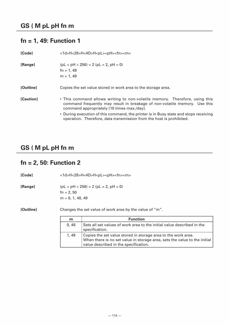
— 114 —
GS ( M pL pH fn m
fn = 1, 49: Function 1
[Code] <1d>H<28>H<4D>H<pL><pH><fn><m>
[Range] (pL + pH × 256) = 2 (pL = 2, pH = 0)fn = 1, 49m = 1, 49
[Outline] Copies the set value stored in work area to the storage area.
[Caution] • This command allows writing to non-volatile memory. Therefore, using thiscommand frequently may result in breakage of non-volatile memory. Use thiscommand appropriately [10 times max./day].
• During execution of this command, the printer is in Busy state and stops receivingoperation. Therefore, data transmission from the host is prohibited.
GS ( M pL pH fn m
fn = 2, 50: Function 2
[Code] <1d>H<28>H<4D>H<pL><pH><fn><m>
[Range] (pL + pH × 256) = 2 (pL = 2, pH = 0)fn = 2, 50m = 0, 1, 48, 49
[Outline] Changes the set value of work area by the value of “m”.
m Function
0, 48 Sets all set values of work area to the initial value described in thespecification.
1, 49 Copies the set value stored in storage area to the work area.When there is no set value in storage area, sets the value to the initialvalue described in the specification.
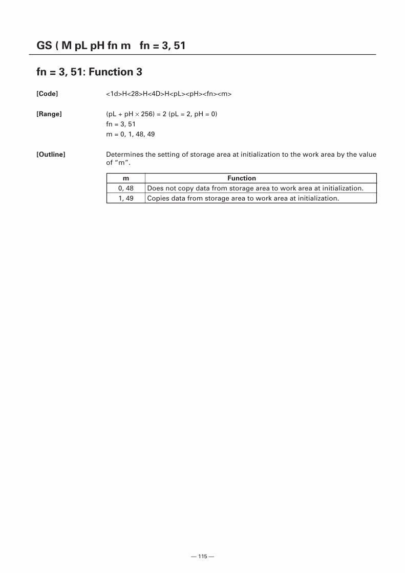
— 115 —
GS ( M pL pH fn m fn = 3, 51
fn = 3, 51: Function 3
[Code] <1d>H<28>H<4D>H<pL><pH><fn><m>
[Range] (pL + pH × 256) = 2 (pL = 2, pH = 0)fn = 3, 51m = 0, 1, 48, 49
[Outline] Determines the setting of storage area at initialization to the work area by the valueof “m”.
m Function
0, 48 Does not copy data from storage area to work area at initialization.1, 49 Copies data from storage area to work area at initialization.
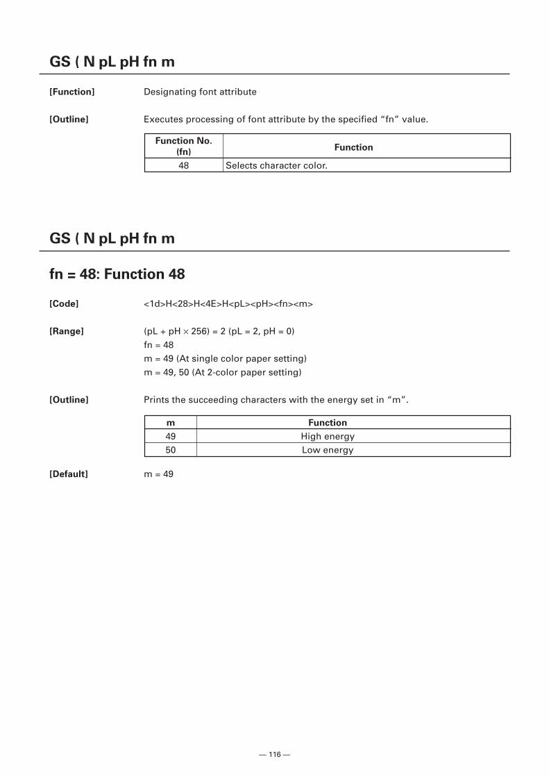
— 116 —
GS ( N pL pH fn m
[Function] Designating font attribute
[Outline] Executes processing of font attribute by the specified “fn” value.
GS ( N pL pH fn m
fn = 48: Function 48
[Code] <1d>H<28>H<4E>H<pL><pH><fn><m>
[Range] (pL + pH × 256) = 2 (pL = 2, pH = 0)fn = 48m = 49 (At single color paper setting)m = 49, 50 (At 2-color paper setting)
[Outline] Prints the succeeding characters with the energy set in “m”.
Function No.Function
(fn)
48 Selects character color.
m Function
49 High energy50 Low energy
[Default] m = 49
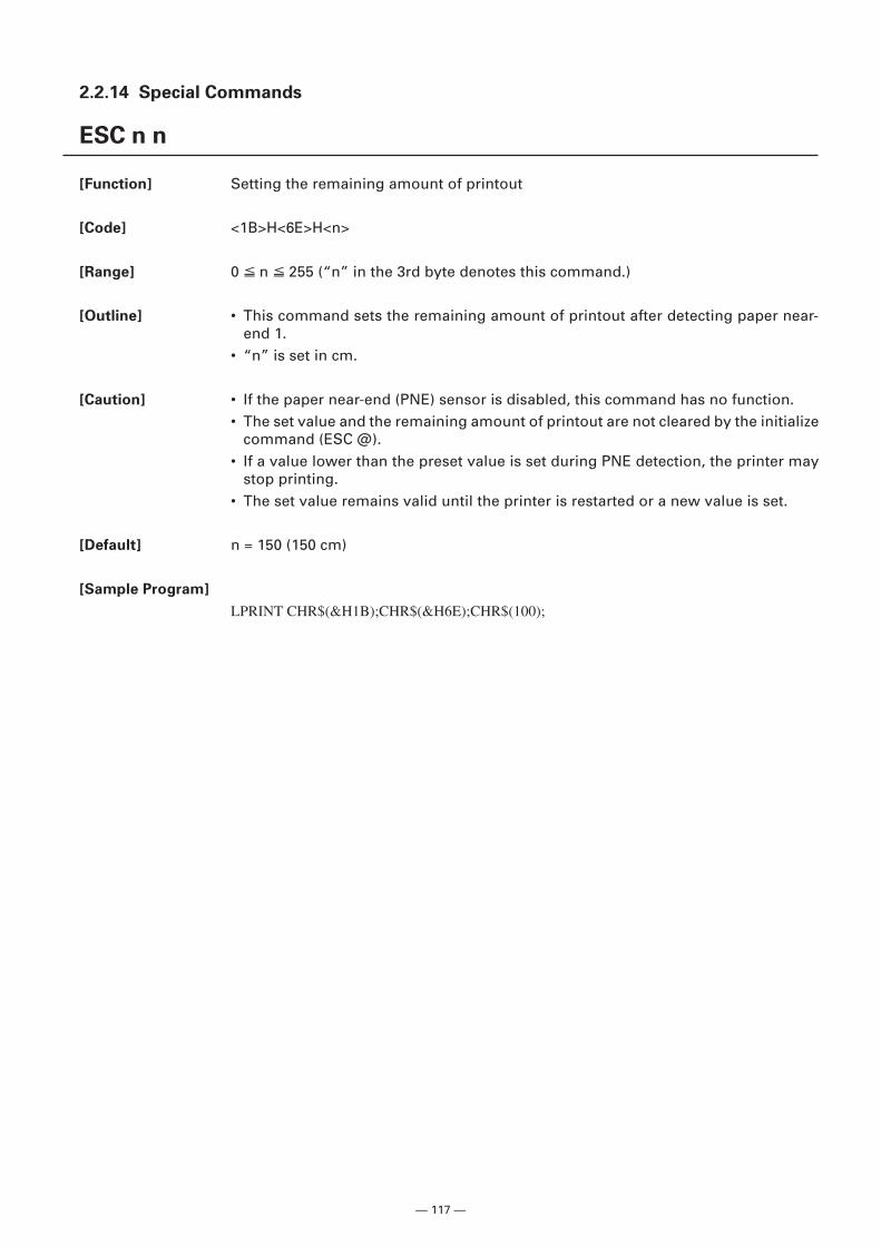
— 117 —
2.2.14 Special Commands
ESC n n
[Function] Setting the remaining amount of printout
[Code] <1B>H<6E>H<n>
[Range] 0 n 255 (“n” in the 3rd byte denotes this command.)
[Outline] • This command sets the remaining amount of printout after detecting paper near-end 1.
• “n” is set in cm.
[Caution] • If the paper near-end (PNE) sensor is disabled, this command has no function.• The set value and the remaining amount of printout are not cleared by the initialize
command (ESC @).• If a value lower than the preset value is set during PNE detection, the printer may
stop printing.• The set value remains valid until the printer is restarted or a new value is set.
[Default] n = 150 (150 cm)
[Sample Program]
LPRINT CHR$(&H1B);CHR$(&H6E);CHR$(100);
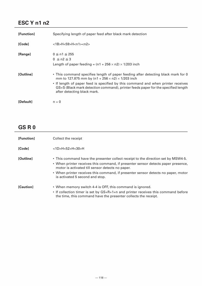
— 118 —
ESC Y n1 n2
[Function] Specifying length of paper feed after black mark detection
[Code] <1B>H<59>H<n1><n2>
[Range] 0 n1 2550 n2 3Length of paper feeding = (n1 + 256 × n2) × 1/203 inch
[Outline] • This command specifies length of paper feeding after detecting black mark for 0mm to 127.875 mm by (n1 + 256 × n2) × 1/203 inch
• If length of paper feed is specified by this command and when printer receivesGS+S (Black mark detection command), printer feeds paper for the specified lengthafter detecting black mark.
[Default] n = 0
GS R 0
[Function] Collect the receipt
[Code] <1D>H<52>H<30>H
[Outline] • This command have the presenter collect receipt to the direction set by MSW4-5.• When printer receives this command, if presenter sensor detects paper presence,
motor is activated till sensor detects no paper.• When printer receives this command, if presenter sensor detects no paper, motor
is activated 5 second and stop.
[Caution] • When memory switch 4-4 is OFF, this command is ignored.• If collection timer is set by GS+R+1+n and printer receives this command before
the time, this command have the presenter collects the receipt.
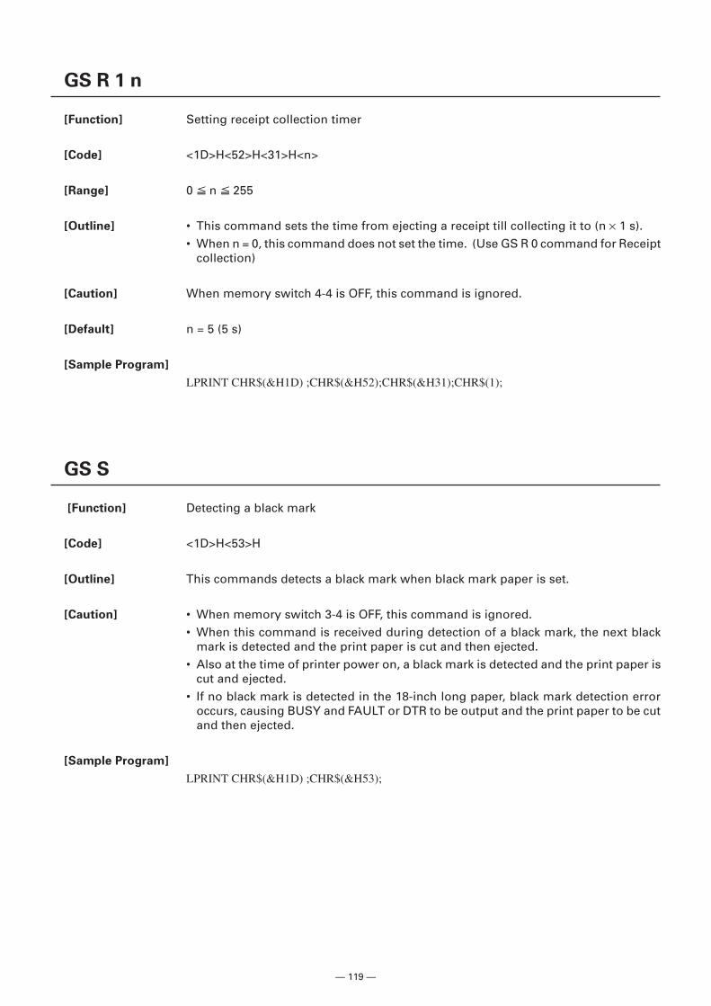
— 119 —
GS R 1 n
[Function] Setting receipt collection timer
[Code] <1D>H<52>H<31>H<n>
[Range] 0 n 255
[Outline] • This command sets the time from ejecting a receipt till collecting it to (n × 1 s).• When n = 0, this command does not set the time. (Use GS R 0 command for Receipt
collection)
[Caution] When memory switch 4-4 is OFF, this command is ignored.
[Default] n = 5 (5 s)
[Sample Program]
LPRINT CHR$(&H1D) ;CHR$(&H52);CHR$(&H31);CHR$(1);
GS S
[Function] Detecting a black mark
[Code] <1D>H<53>H
[Outline] This commands detects a black mark when black mark paper is set.
[Caution] • When memory switch 3-4 is OFF, this command is ignored.• When this command is received during detection of a black mark, the next black
mark is detected and the print paper is cut and then ejected.• Also at the time of printer power on, a black mark is detected and the print paper is
cut and ejected.• If no black mark is detected in the 18-inch long paper, black mark detection error
occurs, causing BUSY and FAULT or DTR to be output and the print paper to be cutand then ejected.
[Sample Program]
LPRINT CHR$(&H1D) ;CHR$(&H53);
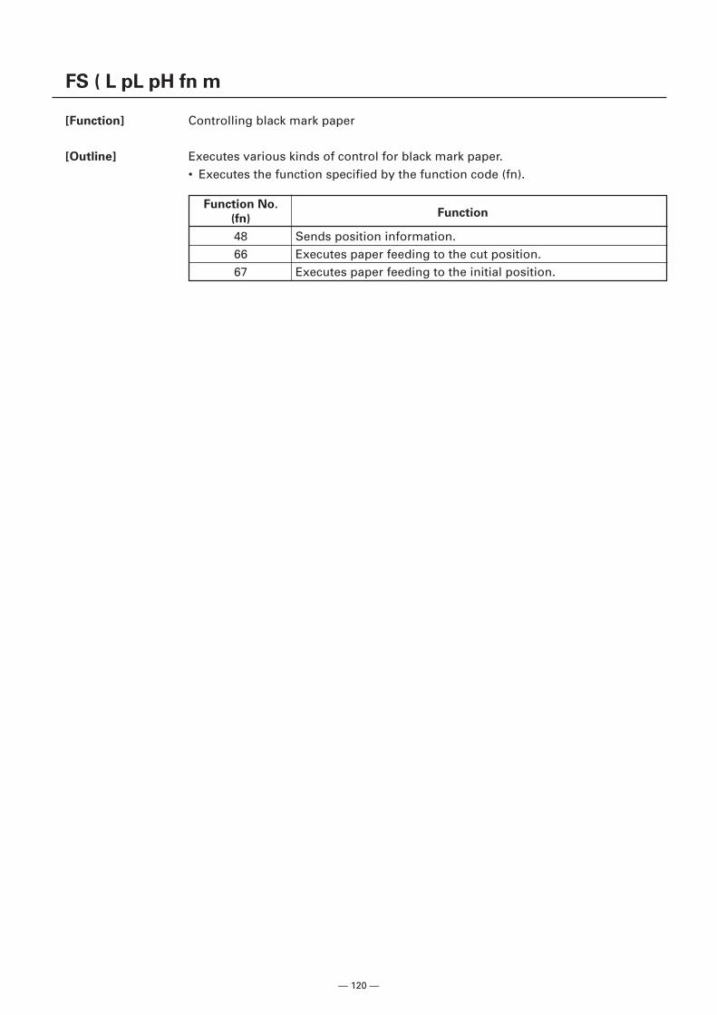
— 120 —
FS ( L pL pH fn m
[Function] Controlling black mark paper
[Outline] Executes various kinds of control for black mark paper.• Executes the function specified by the function code (fn).
Function No.Function
(fn)
48 Sends position information.66 Executes paper feeding to the cut position.67 Executes paper feeding to the initial position.
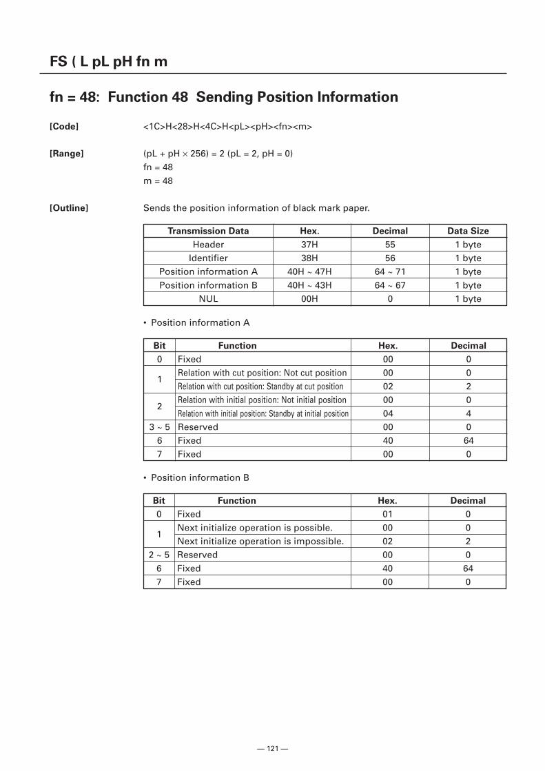
— 121 —
FS ( L pL pH fn m
fn = 48: Function 48 Sending Position Information
[Code] <1C>H<28>H<4C>H<pL><pH><fn><m>
[Range] (pL + pH × 256) = 2 (pL = 2, pH = 0)fn = 48m = 48
[Outline] Sends the position information of black mark paper.
• Position information B
Transmission Data Hex. Decimal Data Size
Header 37H 55 1 byteIdentifier 38H 56 1 byte
Position information A 40H ~ 47H 64 ~ 71 1 bytePosition information B 40H ~ 43H 64 ~ 67 1 byte
NUL 00H 0 1 byte
• Position information A
Bit Function Hex. Decimal
0 Fixed 00 0
1Relation with cut position: Not cut position 00 0Relation with cut position: Standby at cut position 02 2
2Relation with initial position: Not initial position 00 0Relation with initial position: Standby at initial position 04 4
3 ~ 5 Reserved 00 06 Fixed 40 647 Fixed 00 0
Bit Function Hex. Decimal
0 Fixed 01 0
1Next initialize operation is possible. 00 0Next initialize operation is impossible. 02 2
2 ~ 5 Reserved 00 06 Fixed 40 647 Fixed 00 0
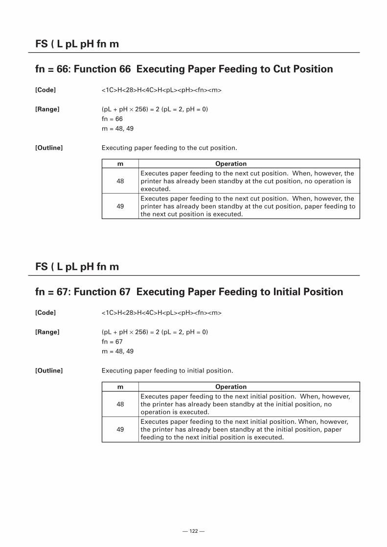
— 122 —
FS ( L pL pH fn m
fn = 66: Function 66 Executing Paper Feeding to Cut Position
[Code] <1C>H<28>H<4C>H<pL><pH><fn><m>
[Range] (pL + pH × 256) = 2 (pL = 2, pH = 0)fn = 66m = 48, 49
[Outline] Executing paper feeding to the cut position.
FS ( L pL pH fn m
fn = 67: Function 67 Executing Paper Feeding to Initial Position
[Code] <1C>H<28>H<4C>H<pL><pH><fn><m>
[Range] (pL + pH × 256) = 2 (pL = 2, pH = 0)fn = 67m = 48, 49
[Outline] Executing paper feeding to initial position.
m Operation
Executes paper feeding to the next cut position. When, however, the48 printer has already been standby at the cut position, no operation is
executed.Executes paper feeding to the next cut position. When, however, the
49 printer has already been standby at the cut position, paper feeding tothe next cut position is executed.
m Operation
Executes paper feeding to the next initial position. When, however,48 the printer has already been standby at the initial position, no
operation is executed.Executes paper feeding to the next initial position. When, however,
49 the printer has already been standby at the initial position, paperfeeding to the next initial position is executed.
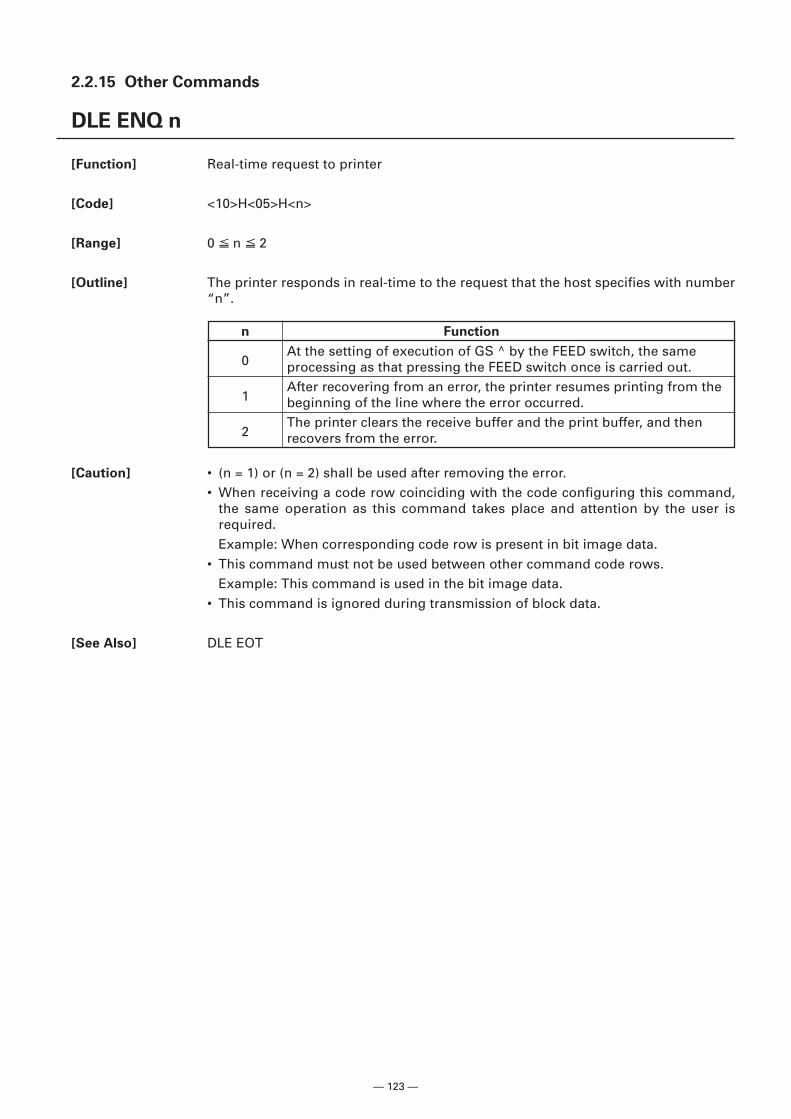
— 123 —
2.2.15 Other Commands
DLE ENQ n
[Function] Real-time request to printer
[Code] <10>H<05>H<n>
[Range] 0 n 2
[Outline] The printer responds in real-time to the request that the host specifies with number“n”.
[Caution] • (n = 1) or (n = 2) shall be used after removing the error.• When receiving a code row coinciding with the code configuring this command,
the same operation as this command takes place and attention by the user isrequired.Example: When corresponding code row is present in bit image data.
• This command must not be used between other command code rows.Example: This command is used in the bit image data.
• This command is ignored during transmission of block data.
[See Also] DLE EOT
n Function
0At the setting of execution of GS ^ by the FEED switch, the sameprocessing as that pressing the FEED switch once is carried out.
1After recovering from an error, the printer resumes printing from thebeginning of the line where the error occurred.
2The printer clears the receive buffer and the print buffer, and thenrecovers from the error.
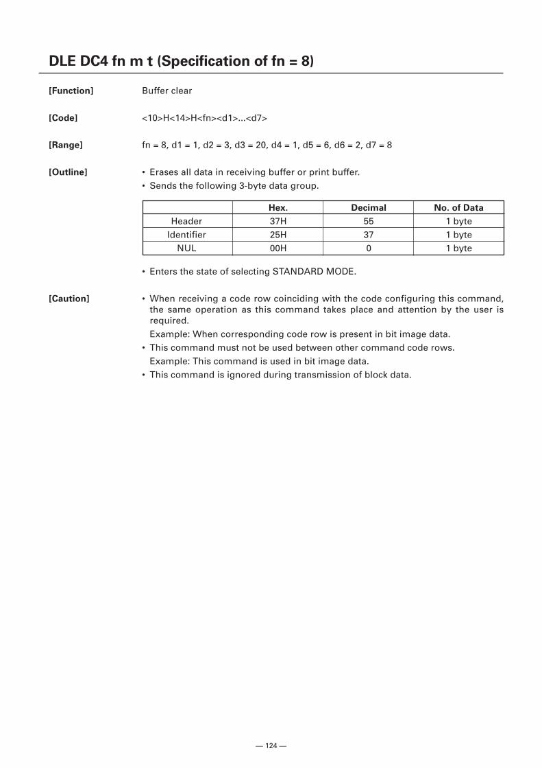
— 124 —
DLE DC4 fn m t (Specification of fn = 8)
[Function] Buffer clear
[Code] <10>H<14>H<fn><d1>...<d7>
[Range] fn = 8, d1 = 1, d2 = 3, d3 = 20, d4 = 1, d5 = 6, d6 = 2, d7 = 8
[Outline] • Erases all data in receiving buffer or print buffer.• Sends the following 3-byte data group.
Hex. Decimal No. of Data
Header 37H 55 1 byteIdentifier 25H 37 1 byte
NUL 00H 0 1 byte
• Enters the state of selecting STANDARD MODE.
[Caution] • When receiving a code row coinciding with the code configuring this command,the same operation as this command takes place and attention by the user isrequired.Example: When corresponding code row is present in bit image data.
• This command must not be used between other command code rows.Example: This command is used in bit image data.
• This command is ignored during transmission of block data.
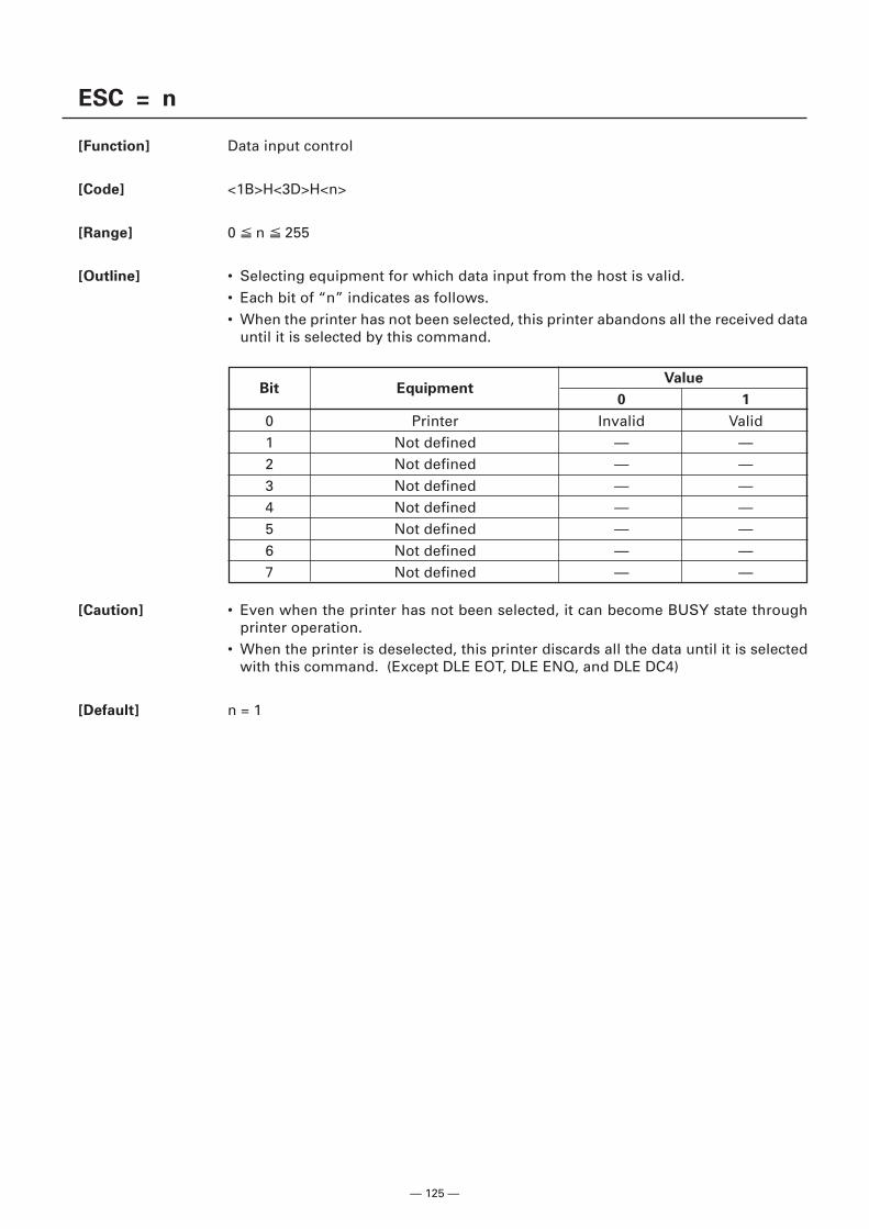
— 125 —
ESC = n
[Function] Data input control
[Code] <1B>H<3D>H<n>
[Range] 0 n 255
[Outline] • Selecting equipment for which data input from the host is valid.• Each bit of “n” indicates as follows.• When the printer has not been selected, this printer abandons all the received data
until it is selected by this command.
[Caution] • Even when the printer has not been selected, it can become BUSY state throughprinter operation.
• When the printer is deselected, this printer discards all the data until it is selectedwith this command. (Except DLE EOT, DLE ENQ, and DLE DC4)
[Default] n = 1
Bit EquipmentValue
0 1
0 Printer Invalid Valid1 Not defined — —2 Not defined — —3 Not defined — —4 Not defined — —5 Not defined — —6 Not defined — —7 Not defined — —
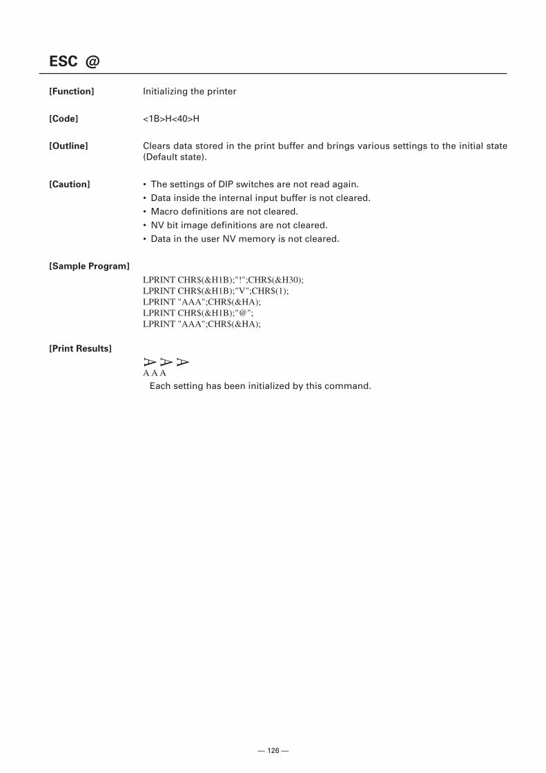
— 126 —
AAA
ESC @
[Function] Initializing the printer
[Code] <1B>H<40>H
[Outline] Clears data stored in the print buffer and brings various settings to the initial state(Default state).
[Caution] • The settings of DIP switches are not read again.• Data inside the internal input buffer is not cleared.• Macro definitions are not cleared.• NV bit image definitions are not cleared.• Data in the user NV memory is not cleared.
[Sample Program]
LPRINT CHR$(&H1B);"!";CHR$(&H30);LPRINT CHR$(&H1B);"V";CHR$(1);LPRINT "AAA";CHR$(&HA);LPRINT CHR$(&H1B);"@";LPRINT "AAA";CHR$(&HA);
[Print Results]
A A A
Each setting has been initialized by this command.
— 127 —
ESC L
[Function] Selecting PAGE MODE
[Code] <1B>H<4C>H
[Outline] Switches from STANDARD MODE to PAGE MODE.
[Caution] • This command is only effective if it entered at the beginning of a line.• This command is not effective if it is entered when in PAGE MODE.• STANDARD MODE is restored when printing specified by FF is finished or when
ESC S is issued.• The character mapping start position will be the point specified by ESC T in the
print area specified by ESC W.• The commands listed below, which have separate settings for PAGE MODE and
STANDARD MODE, are changed to the settings for PAGE MODE use.(1) Spacing setting: ESC SP, FS S(2) Line feed width setting: ESC 2, ESC 3
• The following commands are valid only in PAGE MODE.(1) ESC V Specifying/canceling 90°-right-turned characters.(2) ESC a Aligning the characters.(3) ESC { Specifying/canceling the inverted characters.(4) GS L Setting the left margin.(5) G3S W Setting the print area width.
• The following commands are disabled in PAGE MODE.(1) GS ( A Executes test printing.(2) FS P Prints NV memory bit image.(3) FS q Defines NV memory bit image.(4) GS v 0 Prints raster bit image.
• ESC @ restores STANDARD MODE.
[See Also] Appendix 4.1.4 “Example of using PAGE MODE”FF, CAN, ESC FF, ESC S, ESC T, ESC W, GS W, GS \
— 128 —
ESC S
[Function] Selecting STANDARD MODE
[Code] <1B>H<53>H
[Outline] Switches from PAGE MODE to STANDARD MODE.
[Caution] • This command is only effective if it is entered when in PAGE MODE.• Any data mapped in PAGE MODE is erased.• After this command is executed, the beginning of the line is taken as the next print
start position.• The print area defined by ESC W is initialized.• The commands listed below, which have separate settings for STANDARD MODE
and PAGE MODE, are changed to the settings for STANDARD MODE use.(1) Spacing setting: ESC SP, FS S(2) Line feed width setting: ESC 2, ESC 3
• The following commands are valid only in setting in STANDARD MODE.(1) ESC W Sets the space amount for setting print area in PAGE MODE.(2) ESC T Selects the printing direction of character in PAGE MODE.(3) GS $ Sets the absolute position of character vertical direction in PAGE
MODE.• STANDARD MODE is selected when the printer is turned on or reset, or when ESC
@ is executed.
[See Also] FF, ESC FF, ESC L
ESC RS
[Function] Sound buzzer
[Code] <1B>H<1E>H
[Outline] Sound the buzzer for 200 ms.
[Caution] • This command is buffered before execution.• This command is ignored when MSW3-7 is ON.
[Sample Program]
LPRINT CHR$(&H1B);CHR$(&H1E);
[Execution Result] The buzzer sounds for approx. 200 ms.
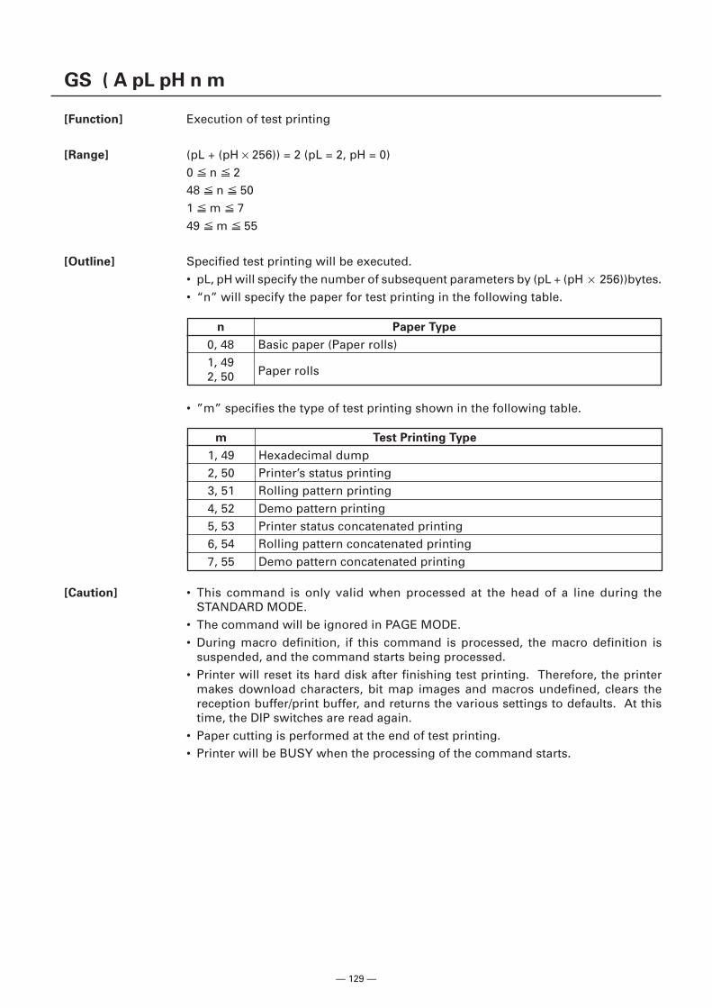
— 129 —
GS ( A pL pH n m
[Function] Execution of test printing
[Range] (pL + (pH × 256)) = 2 (pL = 2, pH = 0)0 n 248 n 501 m 749 m 55
[Outline] Specified test printing will be executed.• pL, pH will specify the number of subsequent parameters by (pL + (pH × 256))bytes.• “n” will specify the paper for test printing in the following table.
[Caution] • This command is only valid when processed at the head of a line during theSTANDARD MODE.
• The command will be ignored in PAGE MODE.• During macro definition, if this command is processed, the macro definition is
suspended, and the command starts being processed.• Printer will reset its hard disk after finishing test printing. Therefore, the printer
makes download characters, bit map images and macros undefined, clears thereception buffer/print buffer, and returns the various settings to defaults. At thistime, the DIP switches are read again.
• Paper cutting is performed at the end of test printing.• Printer will be BUSY when the processing of the command starts.
n Paper Type
0, 48 Basic paper (Paper rolls)1, 49
Paper rolls2, 50
• ”m” specifies the type of test printing shown in the following table.
m Test Printing Type
1, 49 Hexadecimal dump2, 50 Printer’s status printing3, 51 Rolling pattern printing4, 52 Demo pattern printing5, 53 Printer status concatenated printing6, 54 Rolling pattern concatenated printing7, 55 Demo pattern concatenated printing
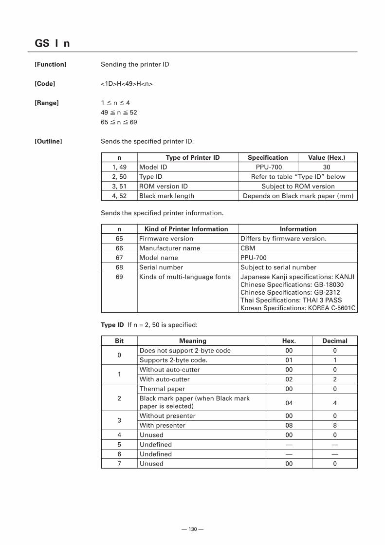
— 130 —
GS I n
[Function] Sending the printer ID
[Code] <1D>H<49>H<n>
[Range] 1 n 449 n 5265 n 69
[Outline] Sends the specified printer ID.
n Type of Printer ID Specification Value (Hex.)
1, 49 Model ID PPU-700 302, 50 Type ID Refer to table “Type ID” below3, 51 ROM version ID Subject to ROM version4, 52 Black mark length Depends on Black mark paper (mm)
Sends the specified printer information.
n Kind of Printer Information Information
65 Firmware version Differs by firmware version.66 Manufacturer name CBM67 Model name PPU-70068 Serial number Subject to serial number69 Kinds of multi-language fonts Japanese Kanji specifications: KANJI
Chinese Specifications: GB-18030Chinese Specifications: GB-2312Thai Specifications: THAI 3 PASSKorean Specifications: KOREA C-5601C
Type ID If n = 2, 50 is specified:
Bit Meaning Hex. Decimal
0Does not support 2-byte code 00 0Supports 2-byte code. 01 1
1Without auto-cutter 00 0With auto-cutter 02 2Thermal paper 00 0
2 Black mark paper (when Black mark04 4paper is selected)
3Without presenter 00 0With presenter 08 8
4 Unused 00 05 Undefined — —6 Undefined — —7 Unused 00 0
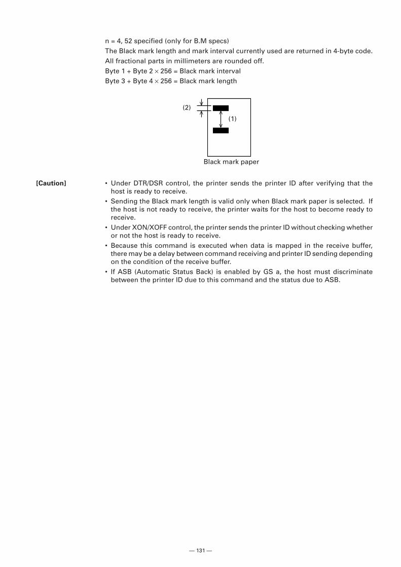
— 131 —
n = 4, 52 specified (only for B.M specs)The Black mark length and mark interval currently used are returned in 4-byte code.All fractional parts in millimeters are rounded off.Byte 1 + Byte 2 × 256 = Black mark intervalByte 3 + Byte 4 × 256 = Black mark length
[Caution] • Under DTR/DSR control, the printer sends the printer ID after verifying that thehost is ready to receive.
• Sending the Black mark length is valid only when Black mark paper is selected. Ifthe host is not ready to receive, the printer waits for the host to become ready toreceive.
• Under XON/XOFF control, the printer sends the printer ID without checking whetheror not the host is ready to receive.
• Because this command is executed when data is mapped in the receive buffer,there may be a delay between command receiving and printer ID sending dependingon the condition of the receive buffer.
• If ASB (Automatic Status Back) is enabled by GS a, the host must discriminatebetween the printer ID due to this command and the status due to ASB.
(2)
(1)
Black mark paper

— 132 —
GS P x y
[Function] Specifying the basic calculation pitch
[Code] <1D>H<50>H<x><y>
[Range] 0 x 2550 y 255
[Outline] • This command sets the horizontal basic calculation pitch to approx. 25.4/x mm(1/x inches), and the vertical basic calculation pitch to approx. 25.4/y mm (1/y inches).
• If x = 0, the horizontal basic calculation pitch is reverted to the default value.• If y = 0, the vertical basic calculation pitch is reverted to the default value.
[Caution] • The horizontal direction is defined as the direction perpendicular to the paper feed,and the vertical direction is defined as the paper feed direction.
• In STANDARD MODE, the following parameters are used regardless of the characterorientation (e.g. inverted or 90°-right-turned).(1) Commands using x: ESC SP, ESC $, ESC \, FS S, GS L, GS W(2) Commands using y: ESC 3, ESC J
• In PAGE MODE, the parameters used depend on the character orientation, as follows:(1) If the start point specified by ESC T is the top left or bottom right (The characters
are mapped in the direction perpendicular to the paper feed):• Commands using x: ESC SP, ESC $, ESC W, ESC \, FS S• Commands using y: ESC 3, ESC J, ESC W, GS $, GS \
(2) If the start point specified by ESC T is the top right or bottom left (The charactersare mapped in the paper feed direction):• Commands using x: ESC 3, ESC J, ESC W, GS $, GS \• Commands using y: ESC SP, ESC $, ESC W, ESC \, FS S
• This command does not affect any other values that are already set.• If calculations made in combination with another command generate fractions,
the fractions are corrected with the minimum pitch of the mechanism, and theremainder is omitted.
[Default] x = 203, y = 203
[See Also] Appendix 4.1 “Explanation on PAGE MODE”ESC SP, ESC $, ESC 3, ESC J, ESC W, ESC \, GS $, GS L, GS W, GS \
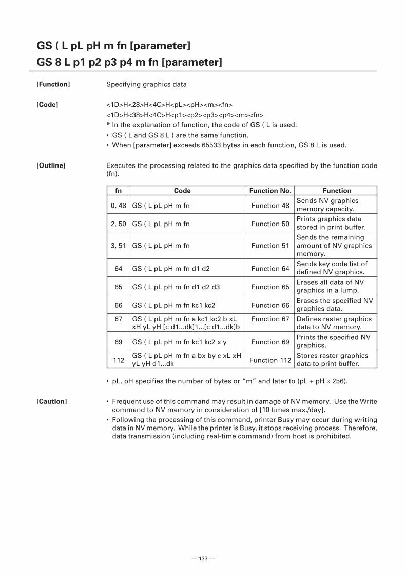
— 133 —
GS ( L pL pH m fn [parameter]
GS 8 L p1 p2 p3 p4 m fn [parameter]
[Function] Specifying graphics data
[Code] <1D>H<28>H<4C>H<pL><pH><m><fn><1D>H<38>H<4C>H<p1><p2><p3><p4><m><fn>* In the explanation of function, the code of GS ( L is used.• GS ( L and GS 8 L ) are the same function.• When [parameter] exceeds 65533 bytes in each function, GS 8 L is used.
[Outline] Executes the processing related to the graphics data specified by the function code(fn).
• pL, pH specifies the number of bytes or “m” and later to (pL + pH × 256).
[Caution] • Frequent use of this command may result in damage of NV memory. Use the Writecommand to NV memory in consideration of [10 times max./day].
• Following the processing of this command, printer Busy may occur during writingdata in NV memory. While the printer is Busy, it stops receiving process. Therefore,data transmission (including real-time command) from host is prohibited.
fn Code Function No. Function
0, 48 GS ( L pL pH m fn Function 48Sends NV graphicsmemory capacity.
2, 50 GS ( L pL pH m fn Function 50Prints graphics datastored in print buffer.Sends the remaining
3, 51 GS ( L pL pH m fn Function 51 amount of NV graphicsmemory.
64 GS ( L pL pH m fn d1 d2 Function 64Sends key code list ofdefined NV graphics.
65 GS ( L pL pH m fn d1 d2 d3 Function 65Erases all data of NVgraphics in a lump.
66 GS ( L pL pH m fn kc1 kc2 Function 66Erases the specified NVgraphics data.
67 GS ( L pL pH m fn a kc1 kc2 b xL Function 67 Defines raster graphicsxH yL yH [c d1...dk]1...[c d1...dk]b data to NV memory.
69 GS ( L pL pH m fn kc1 kc2 x y Function 69Prints the specified NVgraphics.
112GS ( L pL pH m fn a bx by c xL xH
Function 112Stores raster graphics
yL yH d1...dk data to print buffer.
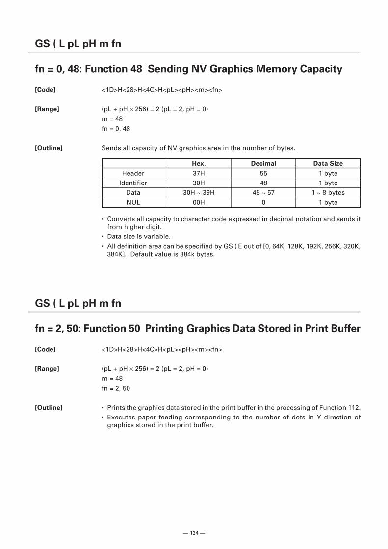
— 134 —
GS ( L pL pH m fn
fn = 0, 48: Function 48 Sending NV Graphics Memory Capacity
[Code] <1D>H<28>H<4C>H<pL><pH><m><fn>
[Range] (pL + pH × 256) = 2 (pL = 2, pH = 0)m = 48fn = 0, 48
[Outline] Sends all capacity of NV graphics area in the number of bytes.
• Converts all capacity to character code expressed in decimal notation and sends itfrom higher digit.
• Data size is variable.• All definition area can be specified by GS ( E out of [0, 64K, 128K, 192K, 256K, 320K,
384K]. Default value is 384k bytes.
GS ( L pL pH m fn
fn = 2, 50: Function 50 Printing Graphics Data Stored in Print Buffer
[Code] <1D>H<28>H<4C>H<pL><pH><m><fn>
[Range] (pL + pH × 256) = 2 (pL = 2, pH = 0)m = 48fn = 2, 50
[Outline] • Prints the graphics data stored in the print buffer in the processing of Function 112.• Executes paper feeding corresponding to the number of dots in Y direction of
graphics stored in the print buffer.
Hex. Decimal Data Size
Header 37H 55 1 byteIdentifier 30H 48 1 byte
Data 30H ~ 39H 48 ~ 57 1 ~ 8 bytesNUL 00H 0 1 byte
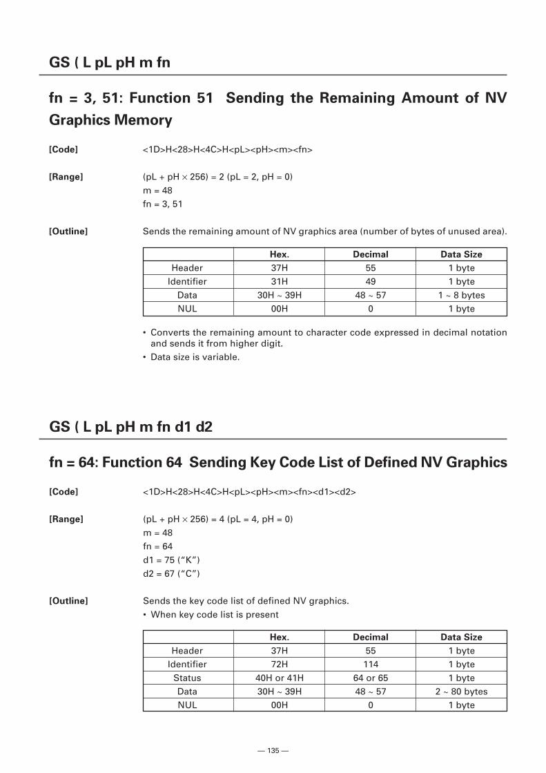
— 135 —
GS ( L pL pH m fn
fn = 3, 51: Function 51 Sending the Remaining Amount of NV
Graphics Memory
[Code] <1D>H<28>H<4C>H<pL><pH><m><fn>
[Range] (pL + pH × 256) = 2 (pL = 2, pH = 0)m = 48fn = 3, 51
[Outline] Sends the remaining amount of NV graphics area (number of bytes of unused area).
• Converts the remaining amount to character code expressed in decimal notationand sends it from higher digit.
• Data size is variable.
Hex. Decimal Data Size
Header 37H 55 1 byteIdentifier 31H 49 1 byte
Data 30H ~ 39H 48 ~ 57 1 ~ 8 bytesNUL 00H 0 1 byte
GS ( L pL pH m fn d1 d2
fn = 64: Function 64 Sending Key Code List of Defined NV Graphics
[Code] <1D>H<28>H<4C>H<pL><pH><m><fn><d1><d2>
[Range] (pL + pH × 256) = 4 (pL = 4, pH = 0)m = 48fn = 64d1 = 75 (“K”)d2 = 67 (“C”)
[Outline] Sends the key code list of defined NV graphics.• When key code list is present
Hex. Decimal Data Size
Header 37H 55 1 byteIdentifier 72H 114 1 byte
Status 40H or 41H 64 or 65 1 byteData 30H ~ 39H 48 ~ 57 2 ~ 80 bytesNUL 00H 0 1 byte
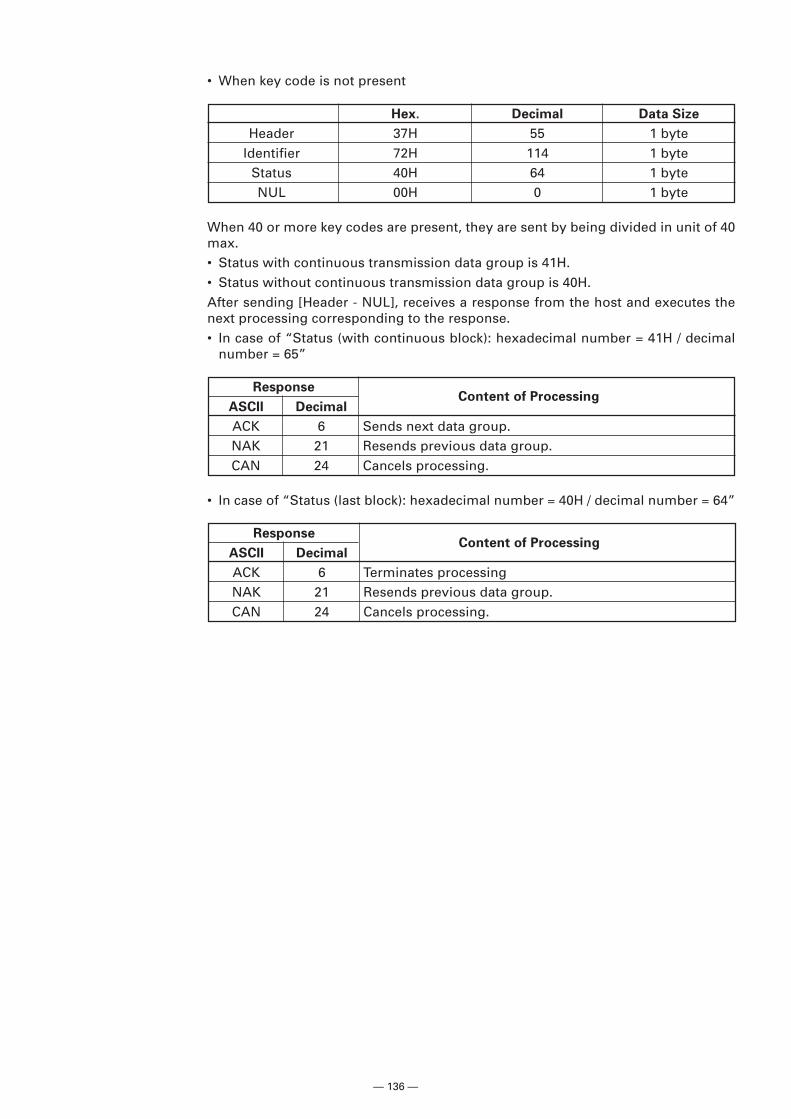
— 136 —
When 40 or more key codes are present, they are sent by being divided in unit of 40max.• Status with continuous transmission data group is 41H.• Status without continuous transmission data group is 40H.After sending [Header - NUL], receives a response from the host and executes thenext processing corresponding to the response.• In case of “Status (with continuous block): hexadecimal number = 41H / decimal
number = 65”
ResponseContent of Processing
ASCII Decimal
ACK 6 Sends next data group.NAK 21 Resends previous data group.CAN 24 Cancels processing.
• When key code is not present
Hex. Decimal Data Size
Header 37H 55 1 byteIdentifier 72H 114 1 byte
Status 40H 64 1 byteNUL 00H 0 1 byte
ResponseContent of Processing
ASCII Decimal
ACK 6 Terminates processingNAK 21 Resends previous data group.CAN 24 Cancels processing.
• In case of “Status (last block): hexadecimal number = 40H / decimal number = 64”
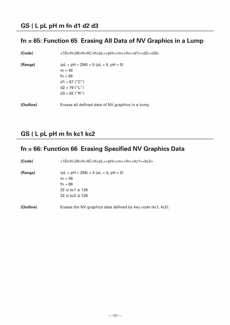
— 137 —
GS ( L pL pH m fn d1 d2 d3
fn = 65: Function 65 Erasing All Data of NV Graphics in a Lump
[Code] <1D>H<28>H<4C>H<pL><pH><m><fn><d1><d2><d3>
[Range] (pL + pH × 256) = 5 (pL = 5, pH = 0)m = 48fn = 65d1 = 67 (“C”)d2 = 76 (“L”)d3 = 82 (“R”)
[Outline] Erases all defined data of NV graphics in a lump.
GS ( L pL pH m fn kc1 kc2
fn = 66: Function 66 Erasing Specified NV Graphics Data
[Code] <1D>H<28>H<4C>H<pL><pH><m><fn><kc1><kc2>
[Range] (pL + pH × 256) = 4 (pL = 4, pH = 0)m = 48fn = 6632 kc1 12632 kc2 126
[Outline] Erases the NV graphics data defined by key code (kc1, kc2).
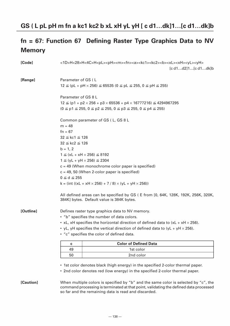
— 138 —
GS ( L pL pH m fn a kc1 kc2 b xL xH yL yH [ c d1…dk]1…[c d1…dk]b
fn = 67: Function 67 Defining Raster Type Graphics Data to NV
Memory
[Code] <1D>H<28>H<4C>H<pL><pH><m><fn><a><kc1><kc2><b><xL><xH><yL><yH>[c d1…d2]1…[c d1…dk]b
[Range] Parameter of GS ( L12 (pL + pH × 256) 65535 (0 pL 255, 0 pH 255)
Parameter of GS 8 L12 (p1 + p2 × 256 + p3 × 65536 + p4 × 16777216) 4294967295(0 p1 255, 0 p2 255, 0 p3 255, 0 p4 255)
Common parameter of GS ( L, GS 8 Lm = 48fn = 6732 kc1 12632 kc2 126b = 1, 21 (xL + xH × 256) 81921 (yL + yH × 256) 2304c = 49 (When monochrome color paper is specified)c = 49, 50 (When 2-color paper is specified)0 d 255k = (int ((xL + xH × 256) + 7 / 8) × (yL + yH × 256))
All defined areas can be specified by GS ( E from [0, 64K, 128K, 192K, 256K, 320K,384K] bytes. Default value is 384K bytes.
[Outline] Defines raster type graphics data to NV memory.• “b” specifies the number of data colors.• xL, xH specifies the horizontal direction of defined data to (xL + xH × 256).• yL, yH specifies the vertical direction of defined data to (yL + yH × 256).• “c” specifies the color of defined data.
c Color of Defined Data
49 1st color50 2nd color
• 1st color denotes black (high energy) in the specified 2-color thermal paper.• 2nd color denotes red (low energy) in the specified 2-color thermal paper.
[Caution] When multiple colors is specified by “b” and the same color is selected by “c”, thecommand processing is terminated at that point, validating the defined data processedso far and the remaining data is read and discarded.
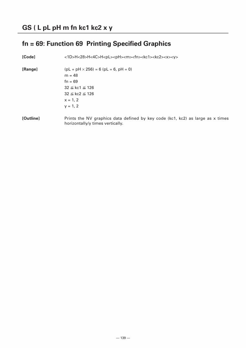
— 139 —
GS ( L pL pH m fn kc1 kc2 x y
fn = 69: Function 69 Printing Specified Graphics
[Code] <1D>H<28>H<4C>H<pL><pH><m><fn><kc1><kc2><x><y>
[Range] (pL + pH × 256) = 6 (pL = 6, pH = 0)m = 48fn = 6932 kc1 12632 kc2 126x = 1, 2y = 1, 2
[Outline] Prints the NV graphics data defined by key code (kc1, kc2) as large as x timeshorizontally/y times vertically.
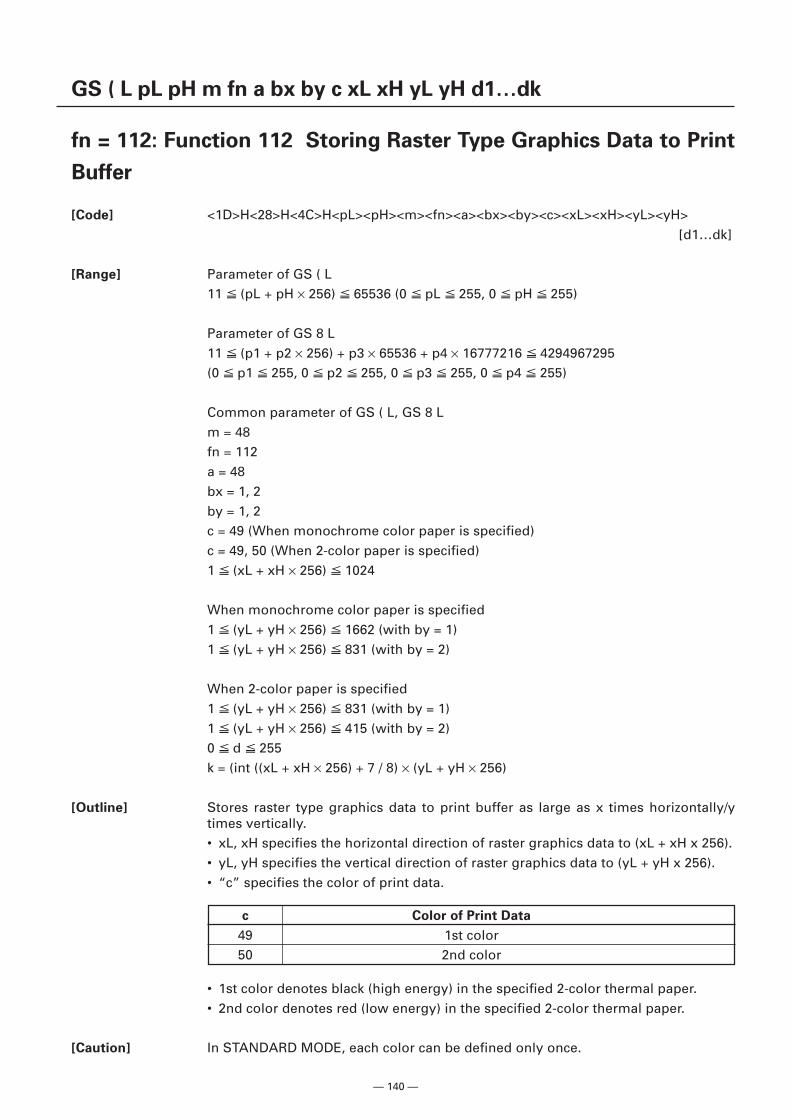
— 140 —
GS ( L pL pH m fn a bx by c xL xH yL yH d1…dk
fn = 112: Function 112 Storing Raster Type Graphics Data to Print
Buffer
[Code] <1D>H<28>H<4C>H<pL><pH><m><fn><a><bx><by><c><xL><xH><yL><yH>[d1…dk]
[Range] Parameter of GS ( L11 (pL + pH × 256) 65536 (0 pL 255, 0 pH 255)
Parameter of GS 8 L11 (p1 + p2 × 256) + p3 × 65536 + p4 × 16777216 4294967295(0 p1 255, 0 p2 255, 0 p3 255, 0 p4 255)
Common parameter of GS ( L, GS 8 Lm = 48fn = 112a = 48bx = 1, 2by = 1, 2c = 49 (When monochrome color paper is specified)c = 49, 50 (When 2-color paper is specified)1 (xL + xH × 256) 1024
When monochrome color paper is specified1 (yL + yH × 256) 1662 (with by = 1)1 (yL + yH × 256) 831 (with by = 2)
When 2-color paper is specified1 (yL + yH × 256) 831 (with by = 1)1 (yL + yH × 256) 415 (with by = 2)0 d 255k = (int ((xL + xH × 256) + 7 / 8) × (yL + yH × 256)
[Outline] Stores raster type graphics data to print buffer as large as x times horizontally/ytimes vertically.• xL, xH specifies the horizontal direction of raster graphics data to (xL + xH x 256).• yL, yH specifies the vertical direction of raster graphics data to (yL + yH x 256).• “c” specifies the color of print data.
• 1st color denotes black (high energy) in the specified 2-color thermal paper.• 2nd color denotes red (low energy) in the specified 2-color thermal paper.
[Caution] In STANDARD MODE, each color can be defined only once.
c Color of Print Data
49 1st color50 2nd color
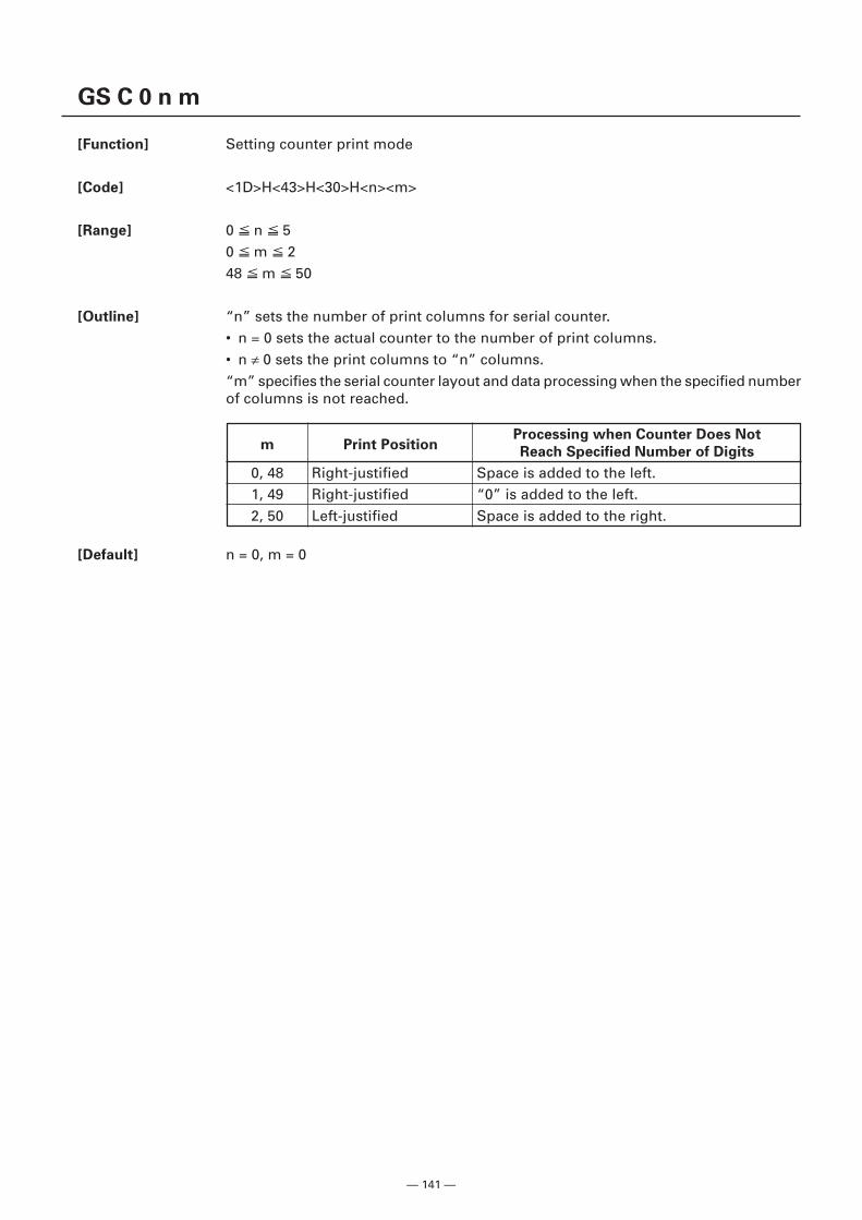
— 141 —
GS C 0 n m
[Function] Setting counter print mode
[Code] <1D>H<43>H<30>H<n><m>
[Range] 0 n 50 m 248 m 50
[Outline] “n” sets the number of print columns for serial counter.• n = 0 sets the actual counter to the number of print columns.• n ≠ 0 sets the print columns to “n” columns.“m” specifies the serial counter layout and data processing when the specified numberof columns is not reached.
[Default] n = 0, m = 0
m Print PositionProcessing when Counter Does Not
Reach Specified Number of Digits
0, 48 Right-justified Space is added to the left.1, 49 Right-justified “0” is added to the left.2, 50 Left-justified Space is added to the right.
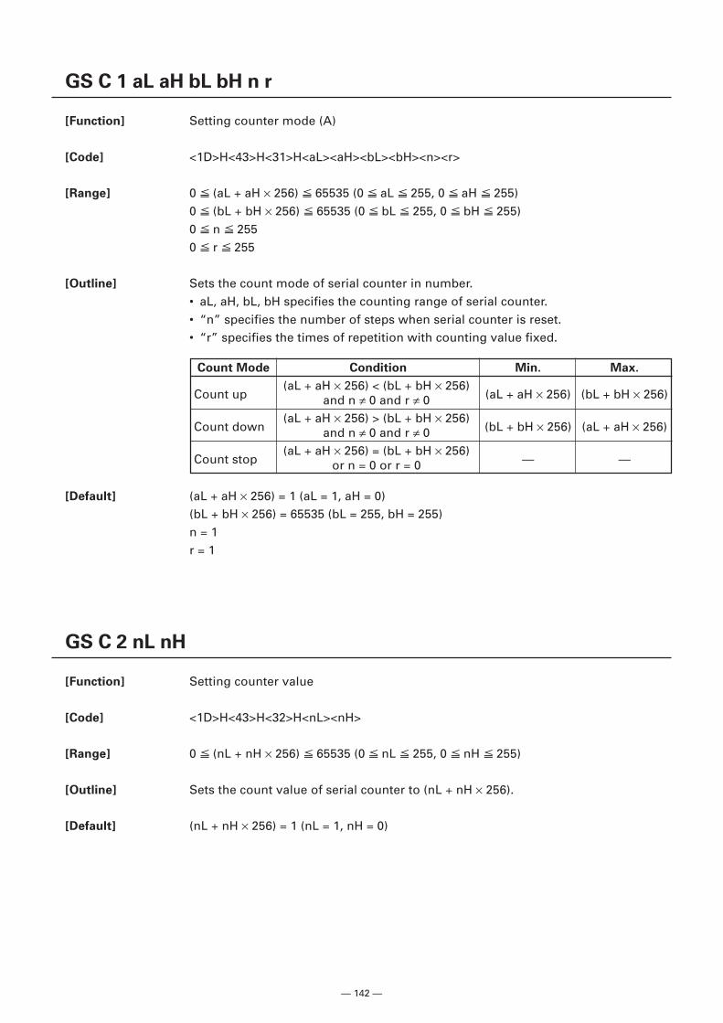
— 142 —
GS C 1 aL aH bL bH n r
[Function] Setting counter mode (A)
[Code] <1D>H<43>H<31>H<aL><aH><bL><bH><n><r>
[Range] 0 (aL + aH × 256) 65535 (0 aL 255, 0 aH 255)0 (bL + bH × 256) 65535 (0 bL 255, 0 bH 255)0 n 2550 r 255
[Outline] Sets the count mode of serial counter in number.• aL, aH, bL, bH specifies the counting range of serial counter.• “n” specifies the number of steps when serial counter is reset.• “r” specifies the times of repetition with counting value fixed.
[Default] (aL + aH × 256) = 1 (aL = 1, aH = 0)(bL + bH × 256) = 65535 (bL = 255, bH = 255)n = 1r = 1
GS C 2 nL nH
[Function] Setting counter value
[Code] <1D>H<43>H<32>H<nL><nH>
[Range] 0 (nL + nH × 256) 65535 (0 nL 255, 0 nH 255)
[Outline] Sets the count value of serial counter to (nL + nH × 256).
[Default] (nL + nH × 256) = 1 (nL = 1, nH = 0)
Count Mode Condition Min. Max.
Count up(aL + aH × 256) < (bL + bH × 256)
(aL + aH × 256) (bL + bH × 256)and n ≠ 0 and r ≠ 0
Count down(aL + aH × 256) > (bL + bH × 256)
(bL + bH × 256) (aL + aH × 256)and n ≠ 0 and r ≠ 0
Count stop(aL + aH × 256) = (bL + bH × 256)
— —or n = 0 or r = 0
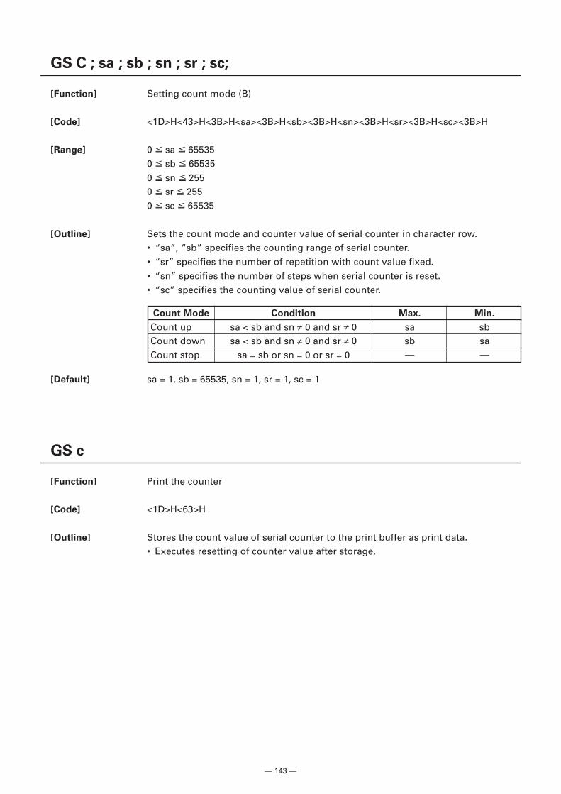
— 143 —
GS C ; sa ; sb ; sn ; sr ; sc;
[Function] Setting count mode (B)
[Code] <1D>H<43>H<3B>H<sa><3B>H<sb><3B>H<sn><3B>H<sr><3B>H<sc><3B>H
[Range] 0 sa 655350 sb 655350 sn 2550 sr 2550 sc 65535
[Outline] Sets the count mode and counter value of serial counter in character row.• “sa”, “sb” specifies the counting range of serial counter.• “sr” specifies the number of repetition with count value fixed.• “sn” specifies the number of steps when serial counter is reset.• “sc” specifies the counting value of serial counter.
[Default] sa = 1, sb = 65535, sn = 1, sr = 1, sc = 1
GS c
[Function] Print the counter
[Code] <1D>H<63>H
[Outline] Stores the count value of serial counter to the print buffer as print data.• Executes resetting of counter value after storage.
Count Mode Condition Max. Min.
Count up sa < sb and sn ≠ 0 and sr ≠ 0 sa sbCount down sa < sb and sn ≠ 0 and sr ≠ 0 sb saCount stop sa = sb or sn = 0 or sr = 0 — —
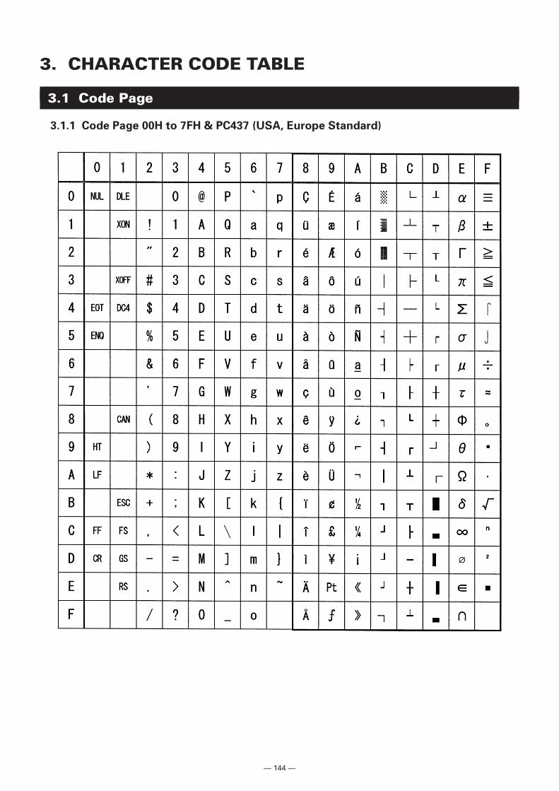
— 144 —
3. CHARACTER CODE TABLE
3.1 Code Page
3.1.1 Code Page 00H to 7FH & PC437 (USA, Europe Standard)
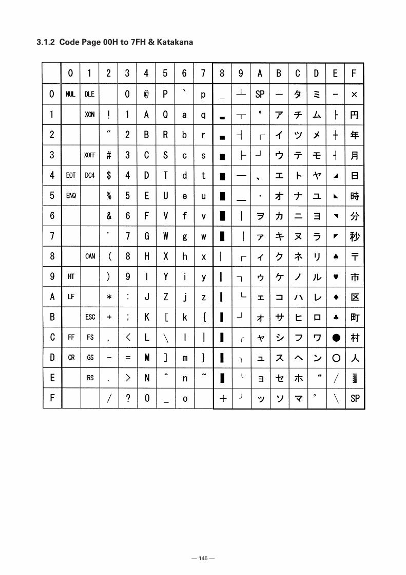
— 145 —
3.1.2 Code Page 00H to 7FH & Katakana
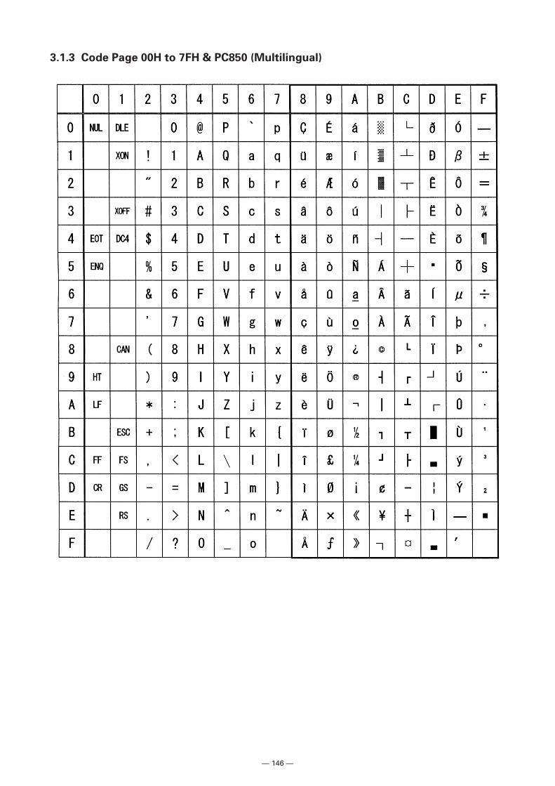
— 146 —
3.1.3 Code Page 00H to 7FH & PC850 (Multilingual)
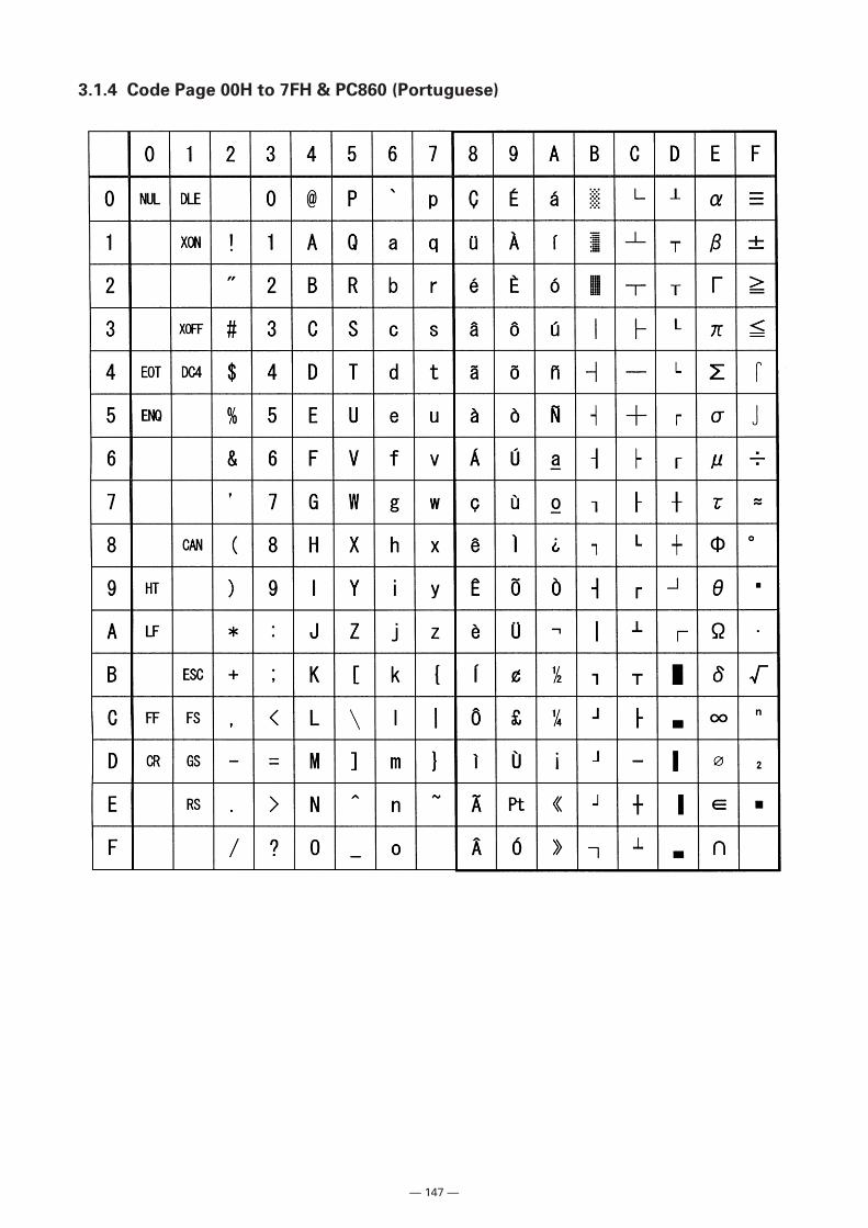
— 147 —
3.1.4 Code Page 00H to 7FH & PC860 (Portuguese)
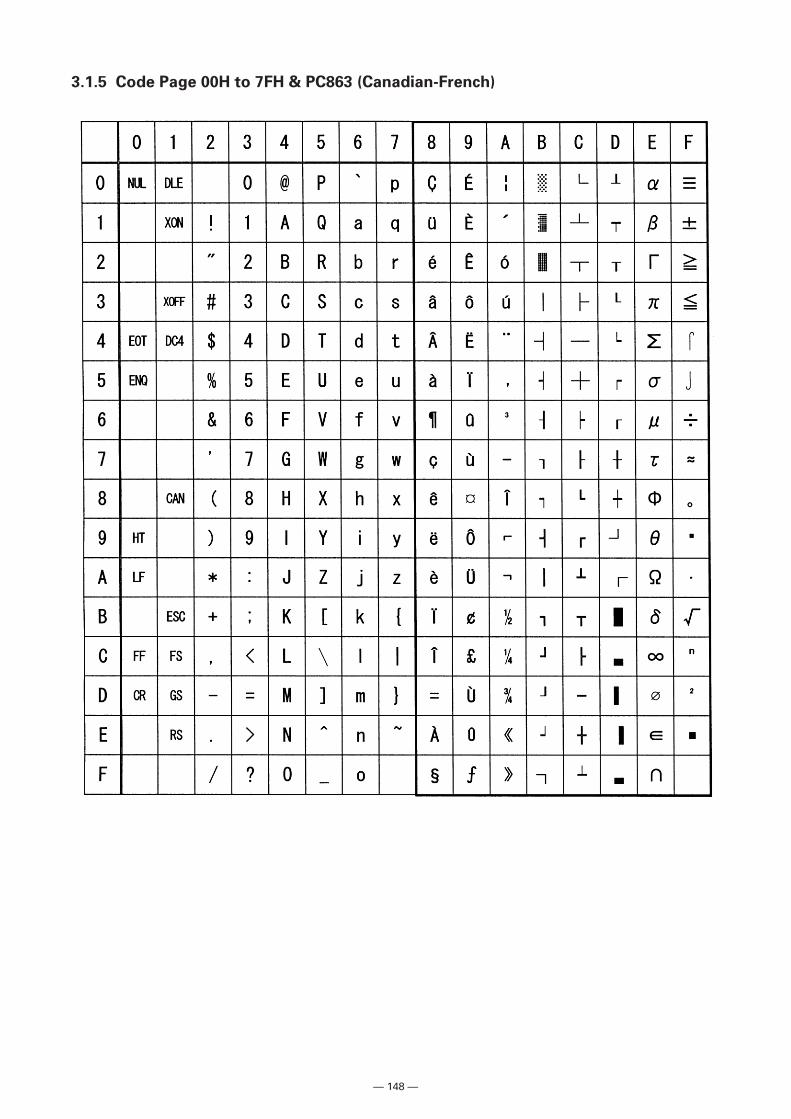
— 148 —
3.1.5 Code Page 00H to 7FH & PC863 (Canadian-French)
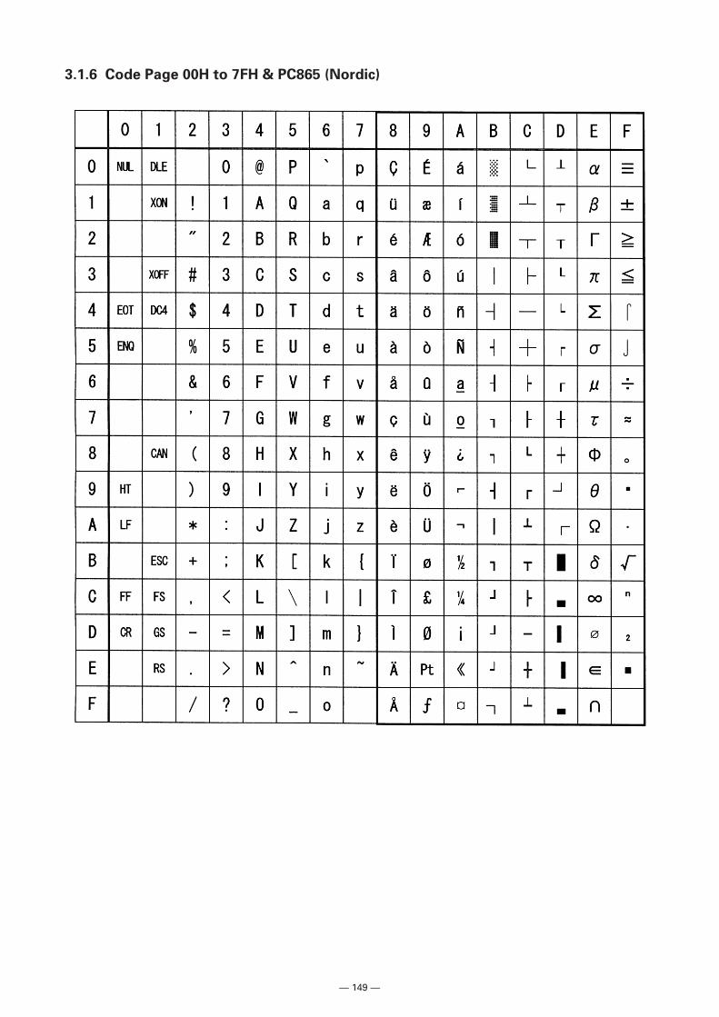
— 149 —
3.1.6 Code Page 00H to 7FH & PC865 (Nordic)
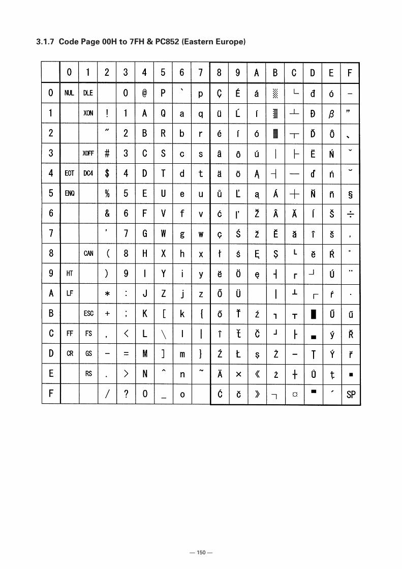
— 150 —
3.1.7 Code Page 00H to 7FH & PC852 (Eastern Europe)
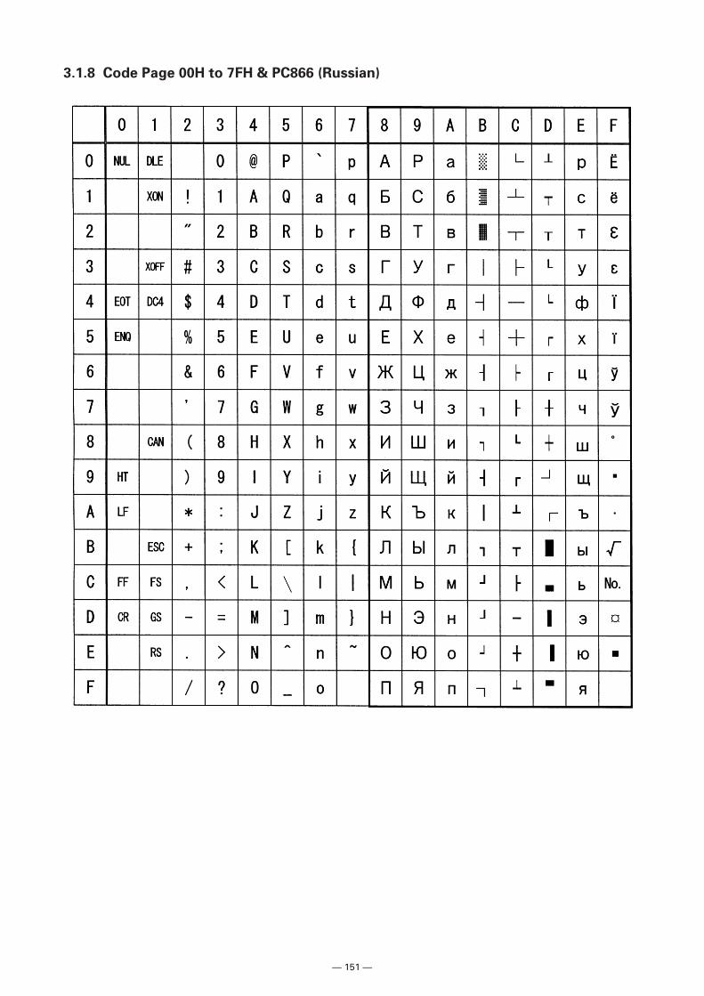
— 151 —
3.1.8 Code Page 00H to 7FH & PC866 (Russian)
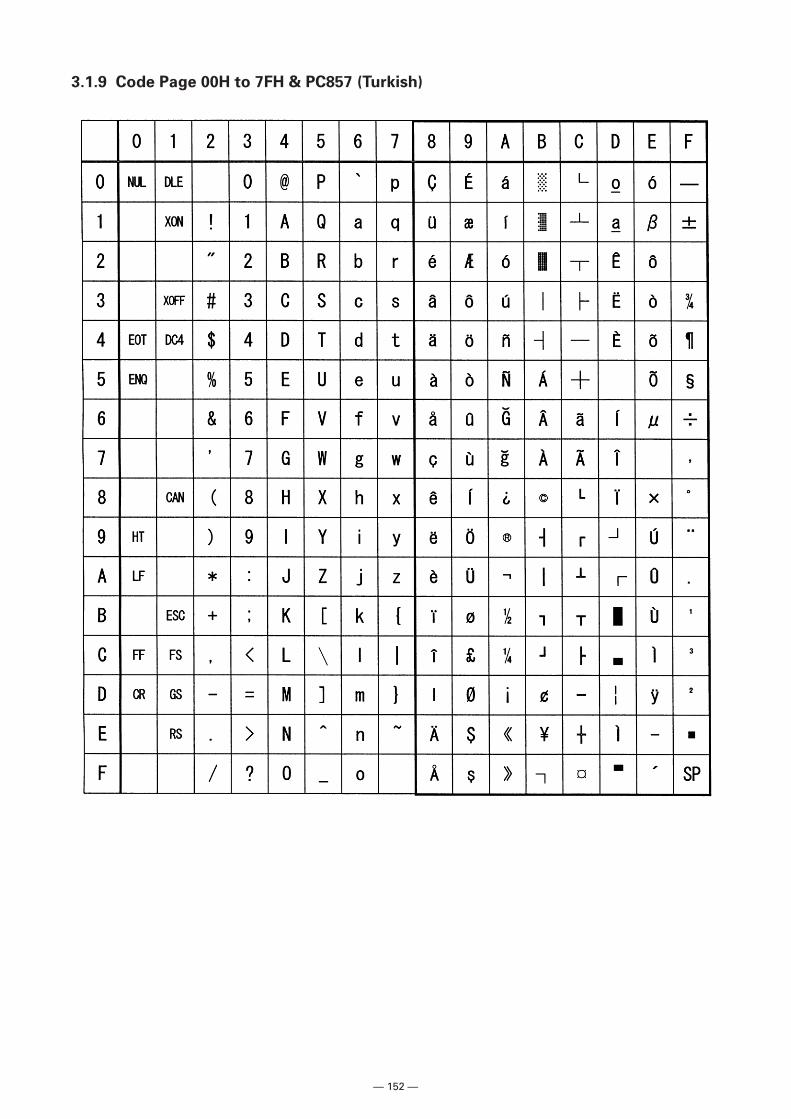
— 152 —
3.1.9 Code Page 00H to 7FH & PC857 (Turkish)
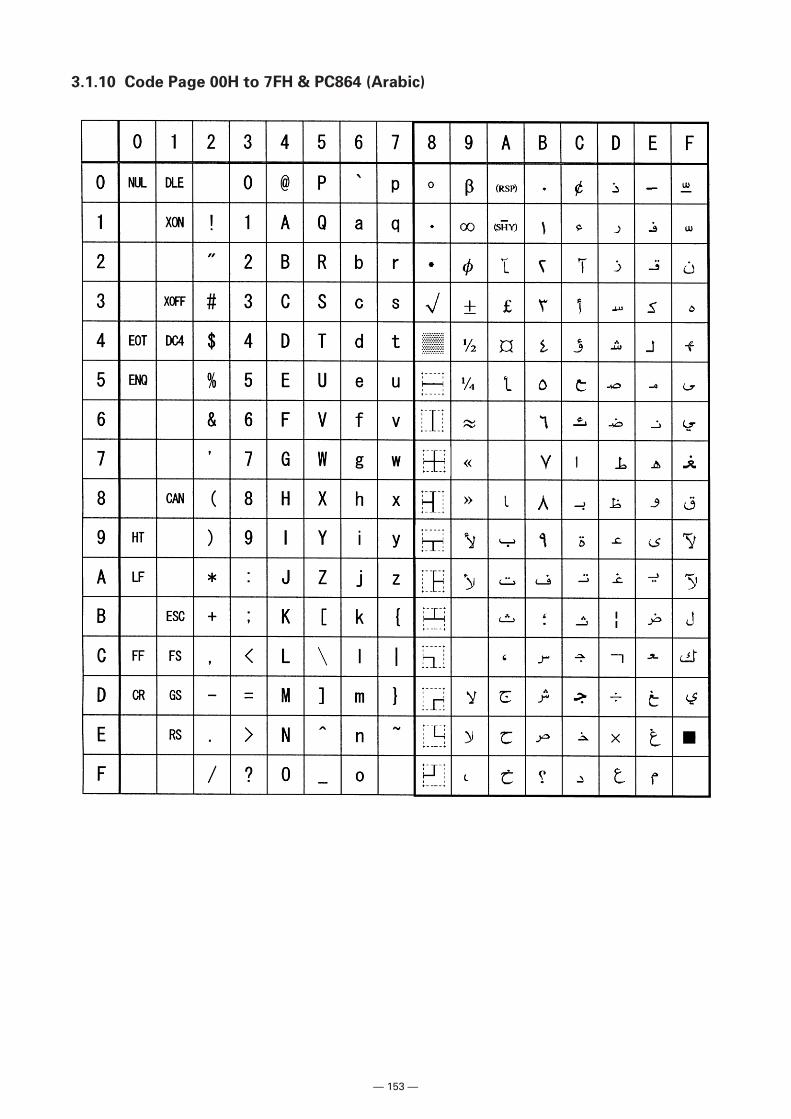
— 153 —
3.1.10 Code Page 00H to 7FH & PC864 (Arabic)
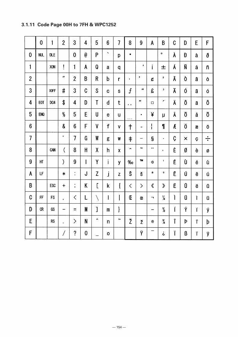
— 154 —
3.1.11 Code Page 00H to 7FH & WPC1252
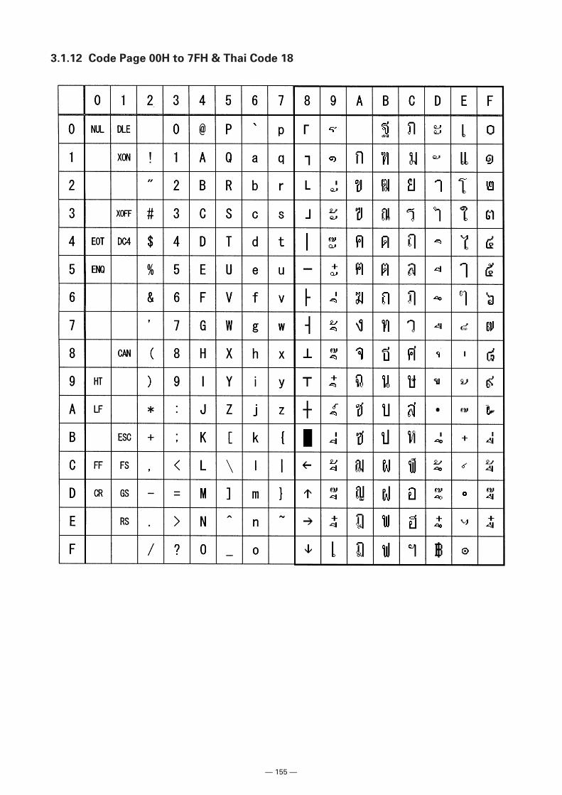
— 155 —
3.1.12 Code Page 00H to 7FH & Thai Code 18
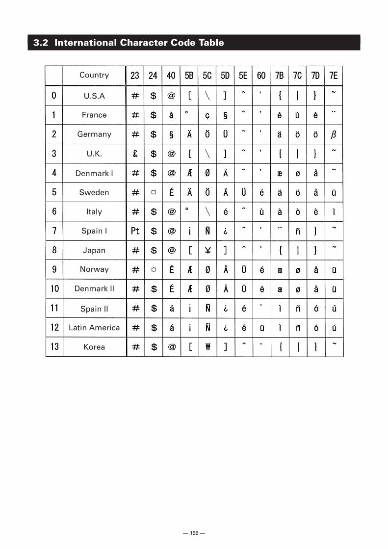
— 156 —
3.2 International Character Code Table
Country
U.K.
Denmark I
Sweden
Italy
Spain I
Japan
Norway
Denmark II
Spain II
Latin America
Korea
Germany
France
U.S.A
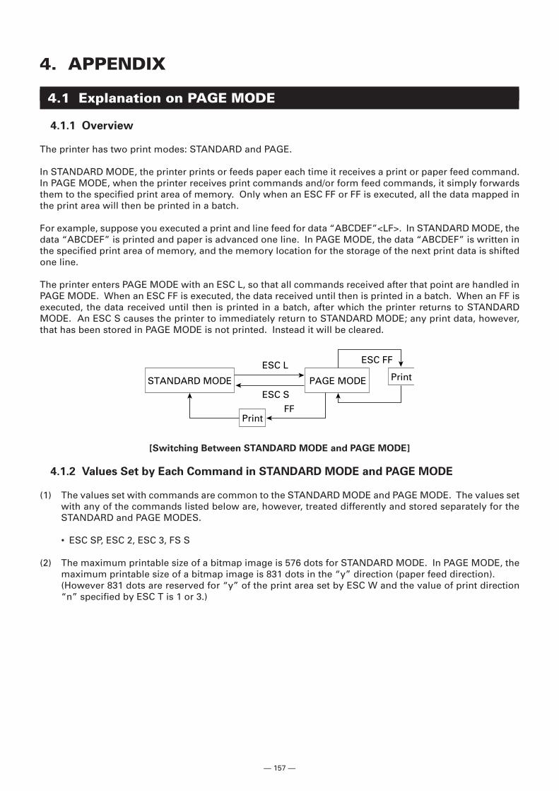
— 157 —
4. APPENDIX
4.1 Explanation on PAGE MODE
4.1.1 Overview
The printer has two print modes: STANDARD and PAGE.
In STANDARD MODE, the printer prints or feeds paper each time it receives a print or paper feed command.In PAGE MODE, when the printer receives print commands and/or form feed commands, it simply forwardsthem to the specified print area of memory. Only when an ESC FF or FF is executed, all the data mapped inthe print area will then be printed in a batch.
For example, suppose you executed a print and line feed for data “ABCDEF”<LF>. In STANDARD MODE, thedata “ABCDEF” is printed and paper is advanced one line. In PAGE MODE, the data “ABCDEF” is written inthe specified print area of memory, and the memory location for the storage of the next print data is shiftedone line.
The printer enters PAGE MODE with an ESC L, so that all commands received after that point are handled inPAGE MODE. When an ESC FF is executed, the data received until then is printed in a batch. When an FF isexecuted, the data received until then is printed in a batch, after which the printer returns to STANDARDMODE. An ESC S causes the printer to immediately return to STANDARD MODE; any print data, however,that has been stored in PAGE MODE is not printed. Instead it will be cleared.
[Switching Between STANDARD MODE and PAGE MODE]
4.1.2 Values Set by Each Command in STANDARD MODE and PAGE MODE
(1) The values set with commands are common to the STANDARD MODE and PAGE MODE. The values setwith any of the commands listed below are, however, treated differently and stored separately for theSTANDARD and PAGE MODES.
• ESC SP, ESC 2, ESC 3, FS S
(2) The maximum printable size of a bitmap image is 576 dots for STANDARD MODE. In PAGE MODE, themaximum printable size of a bitmap image is 831 dots in the “y” direction (paper feed direction).(However 831 dots are reserved for “y” of the print area set by ESC W and the value of print direction“n” specified by ESC T is 1 or 3.)
STANDARD MODE
ESC L ESC FF
ESC S
FF
PAGE MODE Print
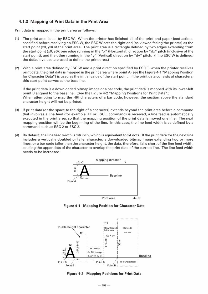
— 158 —
4.1.3 Mapping of Print Data in the Print Area
Print data is mapped in the print area as follows:
(1) The print area is set by ESC W. When the printer has finished all of the print and paper feed actionsspecified before receiving an ESC W, the ESC W sets the right end (as viewed facing the printer) as thestart point (x0, y0) of the print area. The print area is a rectangle defined by two edges extending fromthe start point (x0, y0): one edge running in the “x” (Horizontal) direction by “dx” pitch (inclusive of thestart point), and the other running in the “y” (Vertical) direction by “dy” pitch. (If no ESC W is defined,the default values are used to define the print area.)
(2) With a print area defined by ESC W and a print direction specified by ESC T, when the printer receivesprint data, the print data is mapped in the print area where point A (see the Figure 4-1 “Mapping Positionfor Character Data”) is used as the initial value of the start point. If the print data consists of characters,this start point serves as the baseline.
If the print data is a downloaded bitmap image or a bar code, the print data is mapped with its lower-leftpoint B aligned to the baseline. (See the Figure 4-2 “Mapping Positions for Print Data”.)When attempting to map the HRI characters of a bar code, however, the section above the standardcharacter height will not be printed.
(3) If print data (or the space to the right of a character) extends beyond the print area before a commandthat involves a line feed (for example, LF or ESC J command) is received, a line feed is automaticallyexecuted in the print area, so that the mapping position of the print data is moved one line. The nextmapping position will be the beginning of the line. In this case, the line feed width is as defined by acommand such as ESC 2 or ESC 3.
(4) By default, the line feed width is 1/6 inch, which is equivalent to 34 dots. If the print data for the next lineincludes a vertically doubled or taller character, a downloaded bitmap image extending two or morelines, or a bar code taller than the character height, the data, therefore, falls short of the line feed width,causing the upper dots of the character to overlap the print data of the current line. The line feed widthneeds to be increased.
Figure 4-1 Mapping Position for Character Data
Figure 4-2 Mapping Positions for Print Data
A Baseline
Point A
Print area
Mapping direction
24-3
dx, dy
x0, y0
3
A Baseline
Point BPoint B
Double height character Downloadedbit image
(HRI Characters)
Bar code
GS k m
24-3 24
6*8=
48
GS
hn
24*2
-6=4
2
3 6
Point B
Bit imageEsc * m nL nH
12
12
x*8
Point B
nH*256+nL
GS * x y
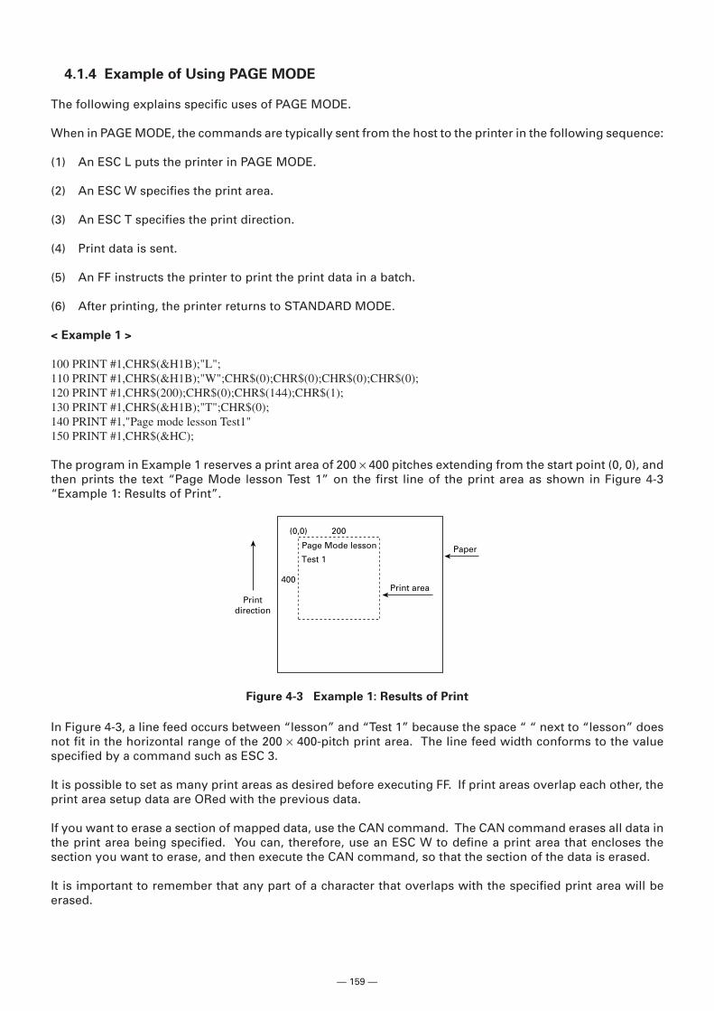
— 159 —
4.1.4 Example of Using PAGE MODE
The following explains specific uses of PAGE MODE.
When in PAGE MODE, the commands are typically sent from the host to the printer in the following sequence:
(1) An ESC L puts the printer in PAGE MODE.
(2) An ESC W specifies the print area.
(3) An ESC T specifies the print direction.
(4) Print data is sent.
(5) An FF instructs the printer to print the print data in a batch.
(6) After printing, the printer returns to STANDARD MODE.
< Example 1 >
100 PRINT #1,CHR$(&H1B);"L";110 PRINT #1,CHR$(&H1B);"W";CHR$(0);CHR$(0);CHR$(0);CHR$(0);120 PRINT #1,CHR$(200);CHR$(0);CHR$(144);CHR$(1);130 PRINT #1,CHR$(&H1B);"T";CHR$(0);140 PRINT #1,"Page mode lesson Test1"150 PRINT #1,CHR$(&HC);
The program in Example 1 reserves a print area of 200 × 400 pitches extending from the start point (0, 0), andthen prints the text “Page Mode lesson Test 1” on the first line of the print area as shown in Figure 4-3“Example 1: Results of Print”.
Figure 4-3 Example 1: Results of Print
Print area
PaperPage Mode lesson
Test 1
200(0,0)
400
Printdirection
In Figure 4-3, a line feed occurs between “lesson” and “Test 1” because the space “ “ next to “lesson” doesnot fit in the horizontal range of the 200 × 400-pitch print area. The line feed width conforms to the valuespecified by a command such as ESC 3.
It is possible to set as many print areas as desired before executing FF. If print areas overlap each other, theprint area setup data are ORed with the previous data.
If you want to erase a section of mapped data, use the CAN command. The CAN command erases all data inthe print area being specified. You can, therefore, use an ESC W to define a print area that encloses thesection you want to erase, and then execute the CAN command, so that the section of the data is erased.
It is important to remember that any part of a character that overlaps with the specified print area will beerased.
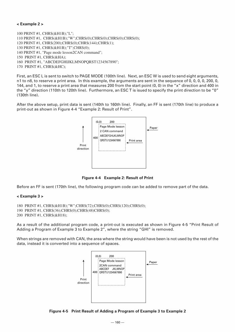
— 160 —
< Example 2 >
100 PRINT #1, CHR$(&H1B);"L";110 PRINT #1, CHR$(&H1B);"W";CHR$(0);CHR$(0);CHR$(0);CHR$(0);120 PRINT #1, CHR$(200);CHR$(0);CHR$(144);CHR$(1);130 PRINT #1, CHR$(&H1B);"T";CHR$(0);140 PRINT #1, "Page mode lesson2CAN command";150 PRINT #1, CHR$(&HA);160 PRINT #1, "ABCDEFGHIJKLMNOPQRST1234567890";170 PRINT #1, CHR$(&HC);
First, an ESC L is sent to switch to PAGE MODE (100th line). Next, an ESC W is used to send eight arguments,n1 to n8, to reserve a print area. In this example, the arguments are sent in the sequence of 0, 0, 0, 0, 200, 0,144, and 1, to reserve a print area that measures 200 from the start point (0, 0) in the “x” direction and 400 inthe “y” direction (110th to 120th line). Furthermore, an ESC T is isued to specify the print direction to be “0”(130th line).
After the above setup, print data is sent (140th to 160th line). Finally, an FF is sent (170th line) to produce aprint-out as shown in Figure 4-4 “Example 2: Result of Print”.
Figure 4-4 Example 2: Result of Print
Print area
PaperPage Mode lesson
2 CAN command
ABCDEFGHIJKLMNOP
QRSTU1234567890
200(0,0)
400
Printdirection
Before an FF is sent (170th line), the following program code can be added to remove part of the data.
< Example 3 >
180 PRINT #1, CHR$(&H1B);"W";CHR$(72);CHR$(0);CHR$(120);CHR$(0);190 PRINT #1, CHR$(36);CHR$(0);CHR$(48)CHR$(0);200 PRINT #1, CHR$(&H18);
As a result of the additional program code, a print-out is executed as shown in Figure 4-5 “Print Result ofAdding a Program of Example 3 to Example 2”, where the string “GHI” is removed.
When strings are removed with CAN, the area where the string would have been is not used by the rest of thedata, instead it is converted into a sequence of spaces.
Figure 4-5 Print Result of Adding a Program of Example 3 to Example 2
Print area
PaperPage Mode lesson
2CAN commandABCDEF JKLMNOPQRSTU1234567890
200(0,0)
400
Printdirection
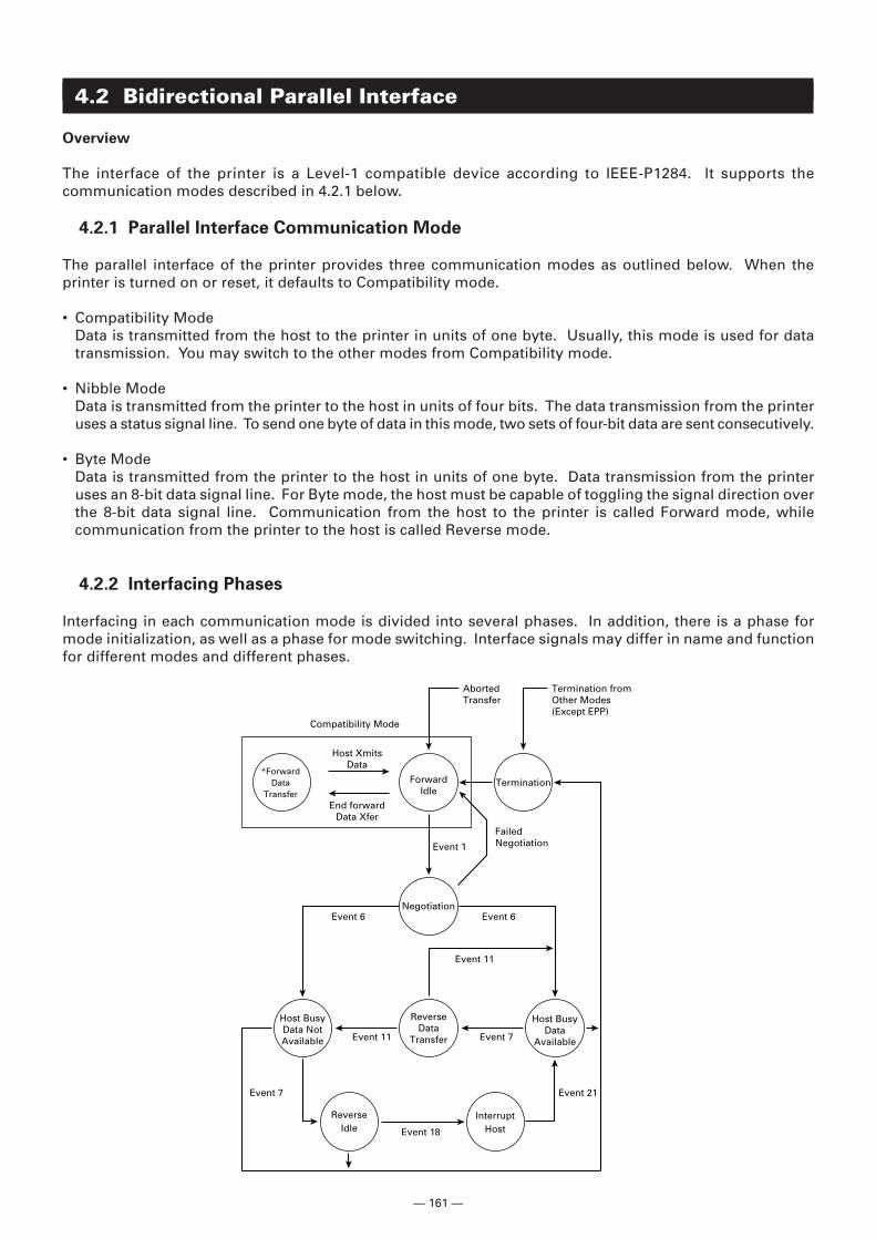
— 161 —
4.2 Bidirectional Parallel Interface
Overview
The interface of the printer is a Level-1 compatible device according to IEEE-P1284. It supports thecommunication modes described in 4.2.1 below.
4.2.1 Parallel Interface Communication Mode
The parallel interface of the printer provides three communication modes as outlined below. When theprinter is turned on or reset, it defaults to Compatibility mode.
• Compatibility ModeData is transmitted from the host to the printer in units of one byte. Usually, this mode is used for datatransmission. You may switch to the other modes from Compatibility mode.
• Nibble ModeData is transmitted from the printer to the host in units of four bits. The data transmission from the printeruses a status signal line. To send one byte of data in this mode, two sets of four-bit data are sent consecutively.
• Byte ModeData is transmitted from the printer to the host in units of one byte. Data transmission from the printeruses an 8-bit data signal line. For Byte mode, the host must be capable of toggling the signal direction overthe 8-bit data signal line. Communication from the host to the printer is called Forward mode, whilecommunication from the printer to the host is called Reverse mode.
4.2.2 Interfacing Phases
Interfacing in each communication mode is divided into several phases. In addition, there is a phase formode initialization, as well as a phase for mode switching. Interface signals may differ in name and functionfor different modes and different phases.
*ForwardData
Transfer
ForwardIdle
ReverseData
Transfer
Host BusyData NotAvailable
Host BusyData
Available
InterruptHost
ReverseIdle
Termination
Compatibility Mode
Negotiation
FailedNegotiationEvent 1
Event 6 Event 6
Event 11
Event 7
Event 7 Event 21
Event 18
Event 11
Host XmitsData
AbortedTransfer
Termination fromOther Modes(Except EPP)
End forwardData Xfer
— 162 —
4.2.3 Negotiation
Overview
Usually, the printer is started in Compatibility mode, which corresponds to the Centronics interface phase.When the host intends to switch to the Nibble or Byte mode, it sends a request and negotiates with theprinter. A general flow of negotiations is given below.
(1) The host sets the IEEE 1284 Active signal to High. In response, the printer moves into the Negotiationphase.
(2) The printer replies whether it can execute the mode requested by the host.
(3) The interface terminates the Negotiation phase and moves into the communication phase.
Negotiation Procedure
The negotiations proceed as follows:
(1) In IEEE 1284 communication mode, the host and printer are in Compatibility mode by default. Theyremain in Compatibility mode as long as the host recognizes the connected device as an IEEE 1284compatible device.
(2) To start negotiations, the host sets the communication mode request bit on the data path. (Event 0)
(3) The host sets IEEE 1284 Active (nSelectln) to High, and HostBusy (nAutoFd) to Low. (Event 1)
(4) The printer responds by setting PtrClk (nAck) to Low, nDataAvail (nFault) to High, Xflag (Select) to High,and AckDatReq (PError) to High. (Event 2)
(5) The host sets HostClk (nStrobe) to Low. In response, the printer latches the data of the communicationmode request bit. (Event 3)
(6) The host sets HostClk (nStrobe) and HostBusy (nAutoFd) to High. (Event 4)
(7) If the printer has communication data to send to the host, it sets AckDataReq (PError) to Low, nDataAvail(nFault) to Low, and Xflag (Select) to the value corresponding to the communication mode. (Event 5)Xflag: Nibble Mode: Low
Byte Mode: High
(8) The printer sets PtrClk (nAck) to High to indicate that it is ready to read status lines. (Event 6)
(9) If the printer has communication data to send to the host, the host moves into the Host Busy Availablephase or Termination phase, and then returns to the Compatibility mode.
(10) If the printer has no communication data to send to the host, the host moves into the Host Busy Data NotAvailable phase or Termination phase, and then returns to the Compatibility mode.
(11) If the printer cannot support the communication mode requested by the host, it sets Xflag (Select) asfollows:When Nibble mode is requested: HighWhen Byte mode is requested: Low
— 163 —
Precautions
(1) The Negotiation phase is triggered when the IEEE 1284 Active signal sent by the host becomes High.
(2) In Compatibility mode, the time when the negotiation process begins is, as a general rule, after the hostsets nStrobe to High and then the printer outputs an nAck pulse.
Once the nStrobe signal is set to High, however, the printer immediately moves into the Negotiationphase when the high state of IEEE 1284 Active is detected, even if the nAck pulse has yet to be output oris being output. In this case, if the printer has returned to Compatibility mode after Termination, nonAck pulse will be output.
(3) Negotiations can be entered from the Busy or Error state of the Compatibility mode. In this case, theprinter will not return to the Busy or Error state before the negotiations, but still remains in the printerstate just after Termination.
(4) If the host requested a communication mode that is not supported by the printer, it must move into theTermination phase and return to the Compatibility mode.
Table 2.4.1 Definitions of Request Bits in IEEE 1284 Communication Mode
Xflag
Bit Definition Hex. Code When In the
Supported Printer
7 Request Extensibility Link 10000000 80H High Low6 Request EPP Mode 01000000 40H High Low5 Request ECP Mode with RLE 00110000 30H High Low4 Request ECP Mode 00010000 10H High Low3 Reserved 00001000 08H High Low
Request Device ID: Return Data UsingNibble Mode Rev Channel Transfer 00000100 04H High High
2 Byte Mode Rev Channel Transfer 00000101 05H High HighECP Mode Transfer without RLE 00010100 14H High LowECP Mode Transfer with RLE 00110100 34H High Low
1 Reserved 00000010 02H High Low0 Byte Mode Reverse Channel Transfer 00000001 01H High High
None Nibble Mode Reverse Channel Transfer 00000000 00H Low Low
Illegal or Contradictory RequestOther than Other than
— Lowabove above
The printer only supports the Nibble and Byte modes. For a request for any other mode, Xflag is set to Low.
Bit Values
(76543210)
— 164 —
Data Communication from Printer to Host
Nibble Mode
In this mode, data is transferred between the printer and the host through the procedure described below.The steps beginning from (1) are applicable when the Negotiation phase has switched to the Host Busy DataAvailable phase. If the Negotiation phase has switched to the Host Busy Data Not Available phase, theprocedure starts at step (9).
(1) After the negotiations for the entry into Nibble mode are completed, the host sets HostBusy (nAutoFd)to Low to indicate that it is ready to receive data from the printer. (Event 7)
(2) The printer places the low-order four bits on the reverse channel data line and sets PtrClk (nAck) to Low.(Events 8 and 9)
(3) The host sets HostBusy (nAutoFd) to High to indicate that it has latched data and received the signal inEvent 9. (Event 10)
(4) The printer sets PtrClk (nAck) to High. This completes transfer of the first nibble. (Event 11)
(5) Steps (1) to (3) are repeated to transfer the high-order four bits, before proceeding to steps (6) and on.
(6) After the host has set HostBusy (nAutoFd) to High (Event 10) and received data, the printer must set thefour status lines as shown below. (Event 13)• PtrBusy (Busy): Returned to the status given in Forward mode.• nDataAvail (nFault): Set to Low if there is data to be sent.• AckDataReq (PError): Set to Low if there is data to be sent.• Xflag (Select): Set to the current mode (i.e., set to Low).
(7) The printer sets PtrClk (nAck) to High. (Event 11)
(8) After Event 11, the host checks the signals set by the printer in Event 13. With this check the hostdetermines:1. Whether there is more data to be sent from the printer to the host;2. And whether data can be transferred from the host to the printer.
(9) If there is no more data to be sent from the printer after the transfer of one byte (two nibbles), the hostchooses one of three status selections:1. Performing Termination and returning to the Compatibility mode.2. Remaining in the Host Busy Data Not Available phase.3. Setting HostBusy (nAutoFd) to Low (Event 7) and moving to the Reverse Idle phase.
(10) If there is more data to be received from the printer, the host chooses one of three status selections:1. Setting HostBusy (nAutoFd) to Low and indicating that the host is ready to receive.2. Remaining in the Host Busy Data Available phase.3. Performing Termination and returning to the Compatibility mode.
(11) If the host selected the Host Busy Data Available phase and set HostBusy (nAutoFd) to Low, the printerrepeats the steps from (2) onwards.
(12) If the host selected the Reverse Idle phase and new data becomes available to be sent from the printer,the printer sets PtrClk to Low to request the host for an interrupt. (Event 18)
(13) The printer sets PtrClk back to High. (Event 19)
(14) Upon receiving a request for interrupt from the printer, the host responds by setting HostBusy (nAutoFd)to High. (Event 20)
(15) Finally, the printer responds to the host by setting AckDataReq (PError) to Low, and then the host movesto the Host Busy Data Available phase. (Event 21)
— 165 —
Byte Mode
In this mode, data is transferred between the printer and the host through the procedure described below.The steps beginning from (1) are applicable when the Negotiation phase has switched to the Host Busy DataAvailable phase. If the Negotiation phase has switched to the Host Busy Data Not Available phase, theprocedure starts at step (9).
(1) After the negotiations for the entry into the Byte mode are complete, the host indicates that it is ready toreceive data from the printer. This is indicated by switching the data bus to a high-impedance state andsetting HostBusy (nAutoFd) to Low. (Events 14 and 7)
(2) The printer places communication data on the data bus. (Event 15)
(3) The printer sets PtrClk (nAck) to Low. (Event 9)
(4) The host sets HostBusy (nAutoFd) to High to indicate that it has latched data and received the signal inEvent 9. (Event 10)
(5) The printer must set the four status lines as shown below. (Event 13)• PtrBusy (Busy): Returned to the status given in the Forward mode.• nDataAvail (nFault): Set to Low if there is data to be sent.• AckDataReq (PError): Set to Low if there is data to be sent.• Xflag (Select): Set to the status given during the last negotiation (i.e., set to Low).
(6) The printer sets PtrClk (nAck) to High (Event 10) and ends the Byte handshake. (Event 11)
(7) The host indicates that it has succeeded in receiving the data. This is indicated by setting HostClk(nStrobe) to Low (Event 16) and then to High. (Event 17)
(8) Events 10 and 16 may occur simultaneously, and Events 7 and 17 may occur simultaneously. (Such aswhen HostBusy and HostClk are used together.)
(9) After transferring one byte of data, the printer signals to the host whether it has more data to transfer.When there is no more data to be received by the host from the printer, the host chooses one of threestatus selections:1. Performing Termination and returning to the Compatibility mode.2. Remaining in the Host Busy Data Not Available phase.3. Setting HostBusy (nAutoFd) to Low and moving to the Reverse Idle phase. (Event 7)
(10) When more data is to be received from the printer, the host chooses one of three status selections:1. Setting HostBusy (nAutoFd) to Low and indicating that the host is ready to receive.2. Remaining in the Host Busy Data Available phase.3. Performing Termination and returning to the Compatibility mode.
— 166 —
Device ID
The device ID is a character string that provides the ID, the type, and other information regarding the printerconnected to the interface. When the printer receives a request for a device ID from the host, it replies withthe following device ID:
<00>H<2E>HMFG : CBM;CMD : ESC/POS;MDL : CT-S300;CLS : PRINTER;
The first two bytes of the device ID indicate the length of the entire device ID. For a description of a requestfor a device ID, refer to the “Negotiation” section.
When the host receives the device ID string of the length indicated by the first two bytes, it must do soconsecutively, without terminating the process until the entire device ID is received. If the process is terminatedhalfway, the printer discards the rest of the string; when the printer receives a new request for the device ID,it sends the device ID beginning from the first character of the ID. After receiving the ID of the length indicatedby the first two bytes, the host must carry out the termination even if the printer has data to send (DataAvailable). If the host does not carry out Termination and tries to receive data, the printer sends the printerstatus.
Termination
Termination is the process of returning to Compatibility mode from the Nibble or Byte modes. Whenperforming Termination, the host sets the signals as follows:
• IEEE 1284 Active (nSelectln): Low• HostBusy (nAutoFd): High (Event 22)
There are two methods of Termination:
(1) Termination through a handshake between the host and the printer(2) Immediate termination
(1) Termination through a handshake between the host and the printer:
When switching from Reverse mode to Compatibility mode, this termination method can be used if theinterface is activated (IEEE 1284 Active: High) and Event 22 has taken place.
1) The printer responds to IEEE 1284 Active by setting PtrBusy (Busy) and nDataAvail (nFault) to High.(Event 23)
2) The printer then inverts Xflag (Select) and sets PtrClk (nAck) to Low. (Event 24)3) The host sets HostBusy (nAutoFd) to Low. (Event 25)4) The printer returns nDataAvail (nFault), Xflag (Select), and AckDataReq (PError) to the status given
in the Compatibility mode, and sets PtrClk (nAck) to High. (Events 26 and 27)5) The host sets HostBusy (nAutoFd) to High to terminate the handshake and return the interface to
the Compatibility Mode Idle phase. (Event 28)6) The printer changes PtrBusy (Busy) to be able to receive data from the host.
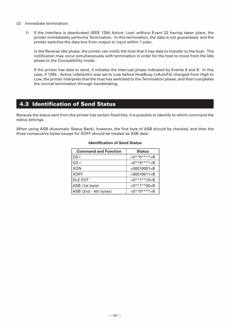
— 167 —
(2) Immediate termination:
1) If the interface is deactivated (IEEE 1284 Active: Low) without Event 22 having taken place, theprinter immediately performs Termination. In this termination, the data is not guaranteed, and theprinter switches the data bus from output to input within 1 µsec.
In the Reverse Idle phase, the printer can notify the host that it has data to transfer to the host. Thenotification may occur simultaneously with termination in order for the host to move from the Idlephase to the Compatibility mode.
If the printer has data to send, it initiates the Interrupt phase indicated by Events 8 and 9. In thiscase, if 1284 - Active (nSelectIn) was set to Low before HostBusy (nAutoFd) changed from High toLow, the printer interprets that the host has switched to the Termination phase, and then completesthe normal termination through handshaking.
4.3 Identification of Send Status
Because the status sent from the printer has certain fixed bits, it is possible to identify to which command thestatus belongs.
When using ASB (Automatic Status Back), however, the first byte of ASB should be checked, and then thethree consecutive bytes except for XOFF should be treated as ASB data.
Identification of Send Status
Command and Function Status
GS I <0**0****>BGS r <0**0****>BXON <00010001>BXOFF <00010011>BDLE EOT <0**1**10>BASB (1st byte) <0**1**00>BASB (2nd - 4th bytes) <0**0****>B
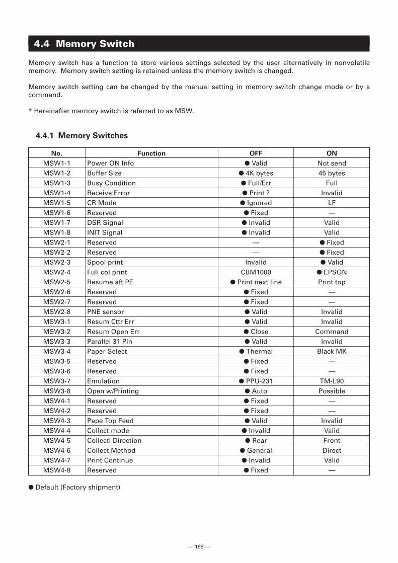
— 168 —
4.4 Memory Switch
Memory switch has a function to store various settings selected by the user alternatively in nonvolatilememory. Memory switch setting is retained unless the memory switch is changed.
Memory switch setting can be changed by the manual setting in memory switch change mode or by acommand.
* Hereinafter memory switch is referred to as MSW.
4.4.1 Memory Switches
No. Function OFF ON
MSW1-1 Power ON Info � Valid Not sendMSW1-2 Buffer Size � 4K bytes 45 bytesMSW1-3 Busy Condition � Full/Err FullMSW1-4 Receive Error � Print ? InvalidMSW1-5 CR Mode � Ignored LFMSW1-6 Reserved � Fixed —MSW1-7 DSR Signal � Invalid ValidMSW1-8 INIT Signal � Invalid ValidMSW2-1 Reserved — � FixedMSW2-2 Reserved — � FixedMSW2-3 Spool print Invalid � ValidMSW2-4 Full col print CBM1000 � EPSONMSW2-5 Resume aft PE � Print next line Print topMSW2-6 Reserved � Fixed —MSW2-7 Reserved � Fixed —MSW2-8 PNE sensor � Valid InvalidMSW3-1 Resum Cttr Err � Valid InvalidMSW3-2 Resum Open Err � Close CommandMSW3-3 Parallel 31 Pin � Valid InvalidMSW3-4 Paper Select � Thermal Black MKMSW3-5 Reserved � Fixed —MSW3-6 Reserved � Fixed —MSW3-7 Emulation � PPU-231 TM-L90MSW3-8 Open w/Printing � Auto PossibleMSW4-1 Reserved � Fixed —MSW4-2 Reserved � Fixed —MSW4-3 Pape Top Feed � Valid InvalidMSW4-4 Collect mode � Invalid ValidMSW4-5 Collecti Direction � Rear FrontMSW4-6 Collect Method � General DirectMSW4-7 Print Continue � Invalid ValidMSW4-8 Reserved � Fixed —
� Default (Factory shipment)
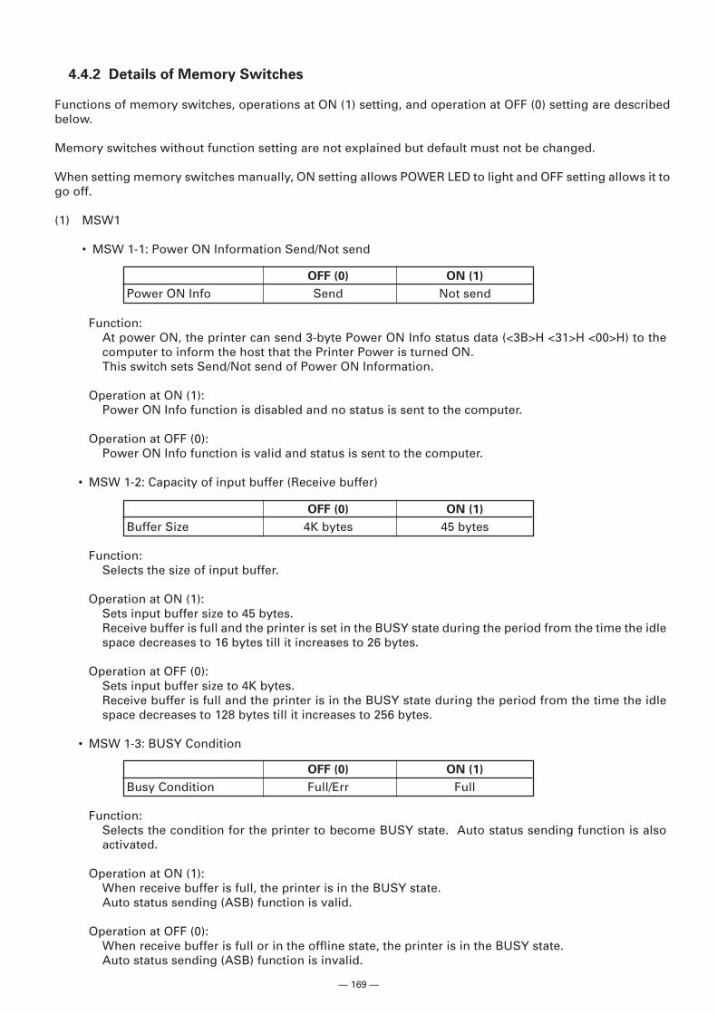
— 169 —
4.4.2 Details of Memory Switches
Functions of memory switches, operations at ON (1) setting, and operation at OFF (0) setting are describedbelow.
Memory switches without function setting are not explained but default must not be changed.
When setting memory switches manually, ON setting allows POWER LED to light and OFF setting allows it togo off.
(1) MSW1
• MSW 1-1: Power ON Information Send/Not send
Function:At power ON, the printer can send 3-byte Power ON Info status data (<3B>H <31>H <00>H) to thecomputer to inform the host that the Printer Power is turned ON.This switch sets Send/Not send of Power ON Information.
Operation at ON (1):Power ON Info function is disabled and no status is sent to the computer.
Operation at OFF (0):Power ON Info function is valid and status is sent to the computer.
• MSW 1-2: Capacity of input buffer (Receive buffer)
Function:Selects the size of input buffer.
Operation at ON (1):Sets input buffer size to 45 bytes.Receive buffer is full and the printer is set in the BUSY state during the period from the time the idlespace decreases to 16 bytes till it increases to 26 bytes.
Operation at OFF (0):Sets input buffer size to 4K bytes.Receive buffer is full and the printer is in the BUSY state during the period from the time the idlespace decreases to 128 bytes till it increases to 256 bytes.
• MSW 1-3: BUSY Condition
OFF (0) ON (1)
Power ON Info Send Not send
OFF (0) ON (1)
Buffer Size 4K bytes 45 bytes
OFF (0) ON (1)
Busy Condition Full/Err Full
Function:Selects the condition for the printer to become BUSY state. Auto status sending function is alsoactivated.
Operation at ON (1):When receive buffer is full, the printer is in the BUSY state.Auto status sending (ASB) function is valid.
Operation at OFF (0):When receive buffer is full or in the offline state, the printer is in the BUSY state.Auto status sending (ASB) function is invalid.
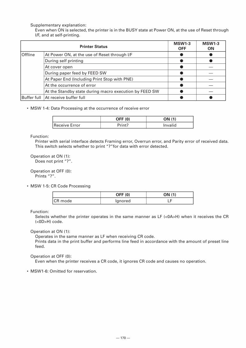
— 170 —
• MSW 1-4: Data Processing at the occurrence of receive error
Supplementary explanation:Even when ON is selected, the printer is in the BUSY state at Power ON, at the use of Reset throughI/F, and at self-printing.
Printer StatusMSW1-3 MSW1-3
OFF ON
Offline At Power ON, at the use of Reset through I/F � �
During self printing � �
At cover open � —During paper feed by FEED SW � —At Paper End (Including Print Stop with PNE) � —At the occurrence of error � —At the Standby state during macro execution by FEED SW � —
Buffer full At receive buffer full � �
OFF (0) ON (1)
Receive Error Print? Invalid
Function:Printer with serial interface detects Framing error, Overrun error, and Parity error of received data.This switch selects whether to print “?”for data with error detected.
Operation at ON (1):Does not print “?”.
Operation at OFF (0):Prints “?”.
• MSW 1-5: CR Code Processing
Function:Selects whether the printer operates in the same manner as LF (<0A>H) when it receives the CR(<0D>H) code.
Operation at ON (1):Operates in the same manner as LF when receiving CR code.Prints data in the print buffer and performs line feed in accordance with the amount of preset linefeed.
Operation at OFF (0):Even when the printer receives a CR code, it ignores CR code and causes no operation.
• MSW1-6: Omitted for reservation.
OFF (0) ON (1)
CR mode Ignored LF
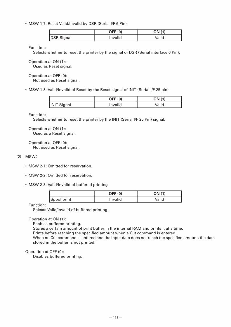
— 171 —
OFF (0) ON (1)
INIT Signal Invalid Valid
• MSW 1-7: Reset Valid/Invalid by DSR (Serial I/F 6 Pin)
Function:Selects whether to reset the printer by the signal of DSR (Serial interface 6 Pin).
Operation at ON (1):Used as Reset signal.
Operation at OFF (0):Not used as Reset signal.
• MSW 1-8: Valid/Invalid of Reset by the Reset signal of INIT (Serial I/F 25 pin)
OFF (0) ON (1)
Spool print Invalid Valid
Function:Selects whether to reset the printer by the INIT (Serial I/F 25 Pin) signal.
Operation at ON (1):Used as a Reset signal.
Operation at OFF (0):Not used as Reset signal.
(2) MSW2
• MSW 2-1: Omitted for reservation.
• MSW 2-2: Omitted for reservation.
• MSW 2-3: Valid/Invalid of buffered printing
OFF (0) ON (1)
DSR Signal Invalid Valid
Function:Selects Valid/Invalid of buffered printing.
Operation at ON (1):Enables buffered printing.Stores a certain amount of print buffer in the internal RAM and prints it at a time.Prints before reaching the specified amount when a Cut command is entered.When no Cut command is entered and the input data does not reach the specified amount, the datastored in the buffer is not printed.
Operation at OFF (0):Disables buffered printing.
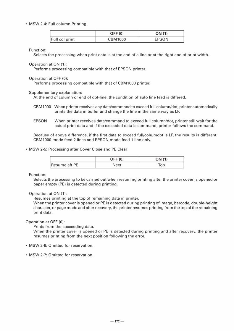
— 172 —
Function:Selects the processing to be carried out when resuming printing after the printer cover is opened orpaper empty (PE) is detected during printing.
Operation at ON (1):Resumes printing at the top of remaining data in printer.When the printer cover is opened or PE is detected during printing of image, barcode, double-heightcharacter, or page mode and after recovery, the printer resumes printing from the top of the remainingprint data.
Operation at OFF (0):Prints from the succeeding data.When the printer cover is opened or PE is detected during printing and after recovery, the printerresumes printing from the next position following the error.
• MSW 2-6: Omitted for reservation.
• MSW 2-7: Omitted for reservation.
OFF (0) ON (1)
Resume aft PE Next Top
OFF (0) ON (1)
Full col print CBM1000 EPSON
Function:Selects the processing when print data is at the end of a line or at the right end of print width.
Operation at ON (1):Performs processing compatible with that of EPSON printer.
Operation at OFF (0):Performs processing compatible with that of CBM1000 printer.
Supplementary explanation:At the end of column or end of dot-line, the condition of auto line feed is differed.
CBM1000 When printer receives any data/command to exceed full column/dot, printer automaticallyprints the data in buffer and change the line in the same way as LF.
EPSON When printer receives data/command to exceed full column/dot, printer still wait for theactual print data and if the exceeded data is command, printer follows the command.
Because of above difference, if the first data to exceed full/colu,mdot is LF, the results is different.CBM1000 mode feed 2 lines and EPSON mode feed 1 line only.
• MSW 2-5: Processing after Cover Close and PE Clear
• MSW 2-4: Full column Printing
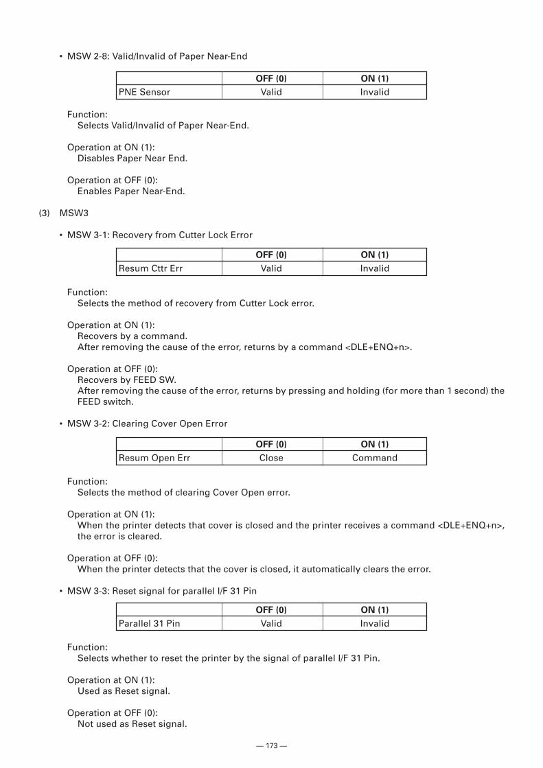
— 173 —
Function:Selects Valid/Invalid of Paper Near-End.
Operation at ON (1):Disables Paper Near End.
Operation at OFF (0):Enables Paper Near-End.
(3) MSW3
• MSW 3-1: Recovery from Cutter Lock Error
OFF (0) ON (1)
PNE Sensor Valid Invalid
OFF (0) ON (1)
Resum Cttr Err Valid Invalid
Function:Selects the method of recovery from Cutter Lock error.
Operation at ON (1):Recovers by a command.After removing the cause of the error, returns by a command <DLE+ENQ+n>.
Operation at OFF (0):Recovers by FEED SW.After removing the cause of the error, returns by pressing and holding (for more than 1 second) theFEED switch.
• MSW 3-2: Clearing Cover Open Error
• MSW 2-8: Valid/Invalid of Paper Near-End
OFF (0) ON (1)
Resum Open Err Close Command
Function:Selects the method of clearing Cover Open error.
Operation at ON (1):When the printer detects that cover is closed and the printer receives a command <DLE+ENQ+n>,the error is cleared.
Operation at OFF (0):When the printer detects that the cover is closed, it automatically clears the error.
• MSW 3-3: Reset signal for parallel I/F 31 Pin
Function:Selects whether to reset the printer by the signal of parallel I/F 31 Pin.
Operation at ON (1):Used as Reset signal.
Operation at OFF (0):Not used as Reset signal.
OFF (0) ON (1)
Parallel 31 Pin Valid Invalid
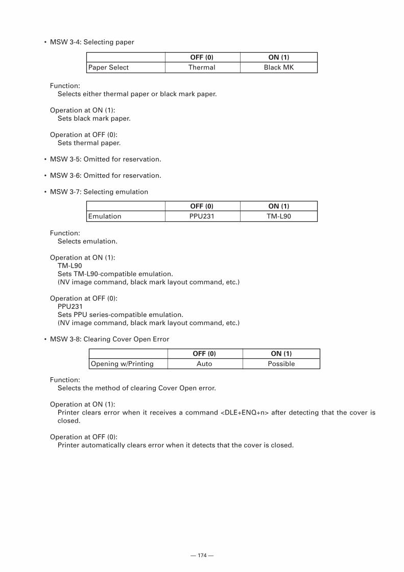
— 174 —
• MSW 3-4: Selecting paper
Function:Selects either thermal paper or black mark paper.
Operation at ON (1):Sets black mark paper.
Operation at OFF (0):Sets thermal paper.
• MSW 3-5: Omitted for reservation.
• MSW 3-6: Omitted for reservation.
• MSW 3-7: Selecting emulation
OFF (0) ON (1)
Paper Select Thermal Black MK
Function:Selects emulation.
Operation at ON (1):TM-L90Sets TM-L90-compatible emulation.(NV image command, black mark layout command, etc.)
Operation at OFF (0):PPU231Sets PPU series-compatible emulation.(NV image command, black mark layout command, etc.)
• MSW 3-8: Clearing Cover Open Error
OFF (0) ON (1)
Emulation PPU231 TM-L90
OFF (0) ON (1)
Opening w/Printing Auto Possible
Function:Selects the method of clearing Cover Open error.
Operation at ON (1):Printer clears error when it receives a command <DLE+ENQ+n> after detecting that the cover isclosed.
Operation at OFF (0):Printer automatically clears error when it detects that the cover is closed.
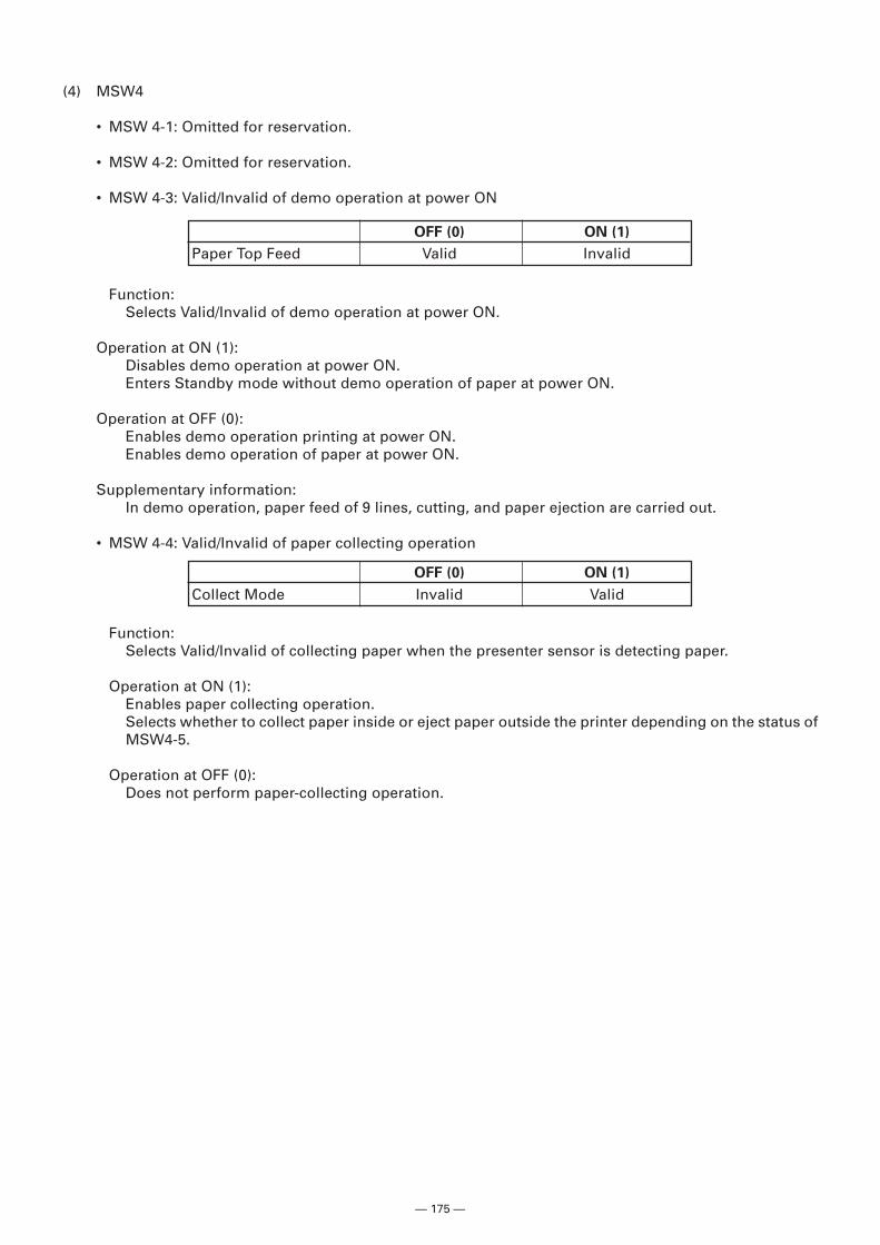
— 175 —
(4) MSW4
• MSW 4-1: Omitted for reservation.
• MSW 4-2: Omitted for reservation.
• MSW 4-3: Valid/Invalid of demo operation at power ON
Function:Selects Valid/Invalid of demo operation at power ON.
Operation at ON (1):Disables demo operation at power ON.Enters Standby mode without demo operation of paper at power ON.
Operation at OFF (0):Enables demo operation printing at power ON.Enables demo operation of paper at power ON.
Supplementary information:In demo operation, paper feed of 9 lines, cutting, and paper ejection are carried out.
• MSW 4-4: Valid/Invalid of paper collecting operation
OFF (0) ON (1)
Paper Top Feed Valid Invalid
Function:Selects Valid/Invalid of collecting paper when the presenter sensor is detecting paper.
Operation at ON (1):Enables paper collecting operation.Selects whether to collect paper inside or eject paper outside the printer depending on the status ofMSW4-5.
Operation at OFF (0):Does not perform paper-collecting operation.
OFF (0) ON (1)
Collect Mode Invalid Valid
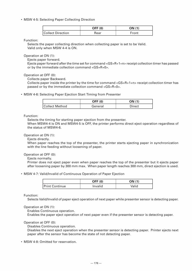
— 176 —
Function:Selects the timing for starting paper ejection from the presenter.When MSW4-4 is ON and MSW4-5 is OFF, the printer performs direct eject operation regardless ofthe status of MSW4-6.
Operation at ON (1):Ejects directly.When paper reaches the top of the presenter, the printer starts ejecting paper in synchronizationwith the line feeding without loosening of paper.
Operation at OFF (0):Ejects normally.Printer does not eject paper even when paper reaches the top of the presenter but it ejects paperafter loosening paper by 300 mm max. When paper length reaches 300 mm, direct ejection is used.
• MSW 4-7: Valid/Invalid of Continuous Operation of Paper Ejection
OFF (0) ON (1)
Collect Direction Rear Front
• MSW 4-5: Selecting Paper Collecting Direction
Function:Selects the paper collecting direction when collecting paper is set to be Valid.Valid only when MSW 4-4 is ON.
Operation at ON (1):Ejects paper forward.Ejects paper forward after the time set for command <GS+R+1+n> receipt collection timer has passedor by the immediate collection command <GS+R+0>.
Operation at OFF (0):Collects paper Backward.Collects paper inside the printer by the time for command <GS+R+1+n> receipt collection timer haspassed or by the immediate collection command <GS+R+0>.
• MSW 4-6: Selecting Paper Ejection Start Timing from Presenter
OFF (0) ON (1)
Collect Method General Direct
Function:Selects Valid/Invalid of paper eject operation of next paper while presenter sensor is detecting paper.
Operation at ON (1):Enables Continuous operation.Enables the paper eject operation of next paper even if the presenter sensor is detecting paper.
Operation at OFF (0):Disables Continuous operation.Disables the next eject operation when the presenter sensor is detecting paper. Printer ejects nextpaper after the sensor has become the state of not detecting paper.
• MSW 4-8: Omitted for reservation.
OFF (0) ON (1)
Print Continue Invalid Valid