Embed Size (px)
Citation preview

1/14
PSNN-201 4-i1202 Safety-Related
[ Project Document No. ]Rev. - ]3Te use of the information contained in this document byayone for any purpose other than that for which it is intended i
not authorized. tn the event the information is used withou"authorization from TOSHIBA CORPORATION, TOSHIBACORPORATION makes no representation or warranty antassumes no liability as to the completeness, accuracy, oJusefulness of the information contained in this document.
TOSHIBA CORPORATIONNUCLEAR ENERGY SYSTEMS & SERVICES DIV.
Commercial Dedication InstructionCustomer Name N/A (As per each Job Order)
Project Name N/A (As per each Job Order)
Item Name N/A (As per each Job Order)
Item Number N/A (As per each Job Order)
Job Number N/A (As per each Job Order)
Product Name PBD module
Model Number ]HINS0430
l*~t ~1U~1IBA cIIf~ATIcH, NIO¶~

TOSHIBA 2/14
9R8K0049 Rev i
Table of Contents
1. Product Identification...................................................................................... 3
2. Product Description ............ ........................................................................... 3
2.1 Definitions.............................................................................................. 3
2.2 Function of Product.................................................................................... 5
2.3 Function of Parent Component........................................................................ 5
3. Safety Related Function ................................................................................... 5
3.1 Functional Classification .............................................................................. 6
4. Critical Characteristics for Design........................................................................ 6
5. Critical Characteristics for Acceptance, Verification Methods and Responsibilities................. 9
5.1 Verification of Physical and Performance Characteristics Depending on Supplier Testing .... 9
5.2 Verification of "Dependability" of Module........................................................ 10
6. Verification Instruction................................................................................... 116.1 Recurring Activities ................................................................................... 11
6.2 Periodic Activities ................... ................................................................ 11
7. Acceptance Documentation .............................................................................. 128. References ......................... i..........................................£.............................. 12
9. Inspection and Test Procedure ............................................................................ 12
10. Supplements ............................................................................................. 13

TOSH IBA 3/149B8K0049 Rev.3
1. Product Identification
a. Part Number: See following table
b. Model Number: HNS0430
c. Drawing Number: 5Q8K0021 Rev.3
d. Manufacturer's Name: TOSHIBA Corporation, Power Systems Company, Power Platform Development
Department (PPDD)
Sub supplier:
Toshiba Design and Manufacturing Service Corporation (TDMS)
e. Manufacturer's Model Number: See following table
f. Manufacturer's Catalog Number: N/A
g. Name plate data: N/A
h. Applicable Material/Part Specification Number: N/A
i. Identification of Parent Component: See Section 2.3
j. Software Version: N/A
k. Firmware Version: N/A
FPGA Code Name FPGA Identification*( )a'c 108101
( )a~c 108900
( )a'c 109001
( 1••109101
( ja'c 109202
( )a,c 109300
( )a'c 109400
* The first 6-digit numeric strings in registration number of FPGA fuse-map
Table 1 Part Number List
Part Number: (Procurement/Purchase Manufacturer's Model Number
Specification Number/ Part Number)
5Q8K0021liP001 HNS0430B00000
2. Product Description2.1 Definitions
a. General Name of Product: PBD module
b. Product Name of Manufacturer: PBD module
c. Description of Terms
* APRM: Average Power Range Monitor, a safety-related subsystem of Neutron Monitoring System
(NMS).
* APRM unit: A parent component of the APRM, FLOW, GAF/ST, TRN, RCV DIO, and LVPS modules.
An APRM unit measures Core Flow Level (safety function) and APRM Level (safety function) using
the LPRM Levels.

TOSHI BA 4/149B8K0049 Rev.3
* CELL module: The CELL module mounted on OPRM unit calculates neutron flux oscillation (i.e.
Normalized Oscillation Signal) (safety function) using LPRM Levels received from the RCV module
mounted in OPRM unit.
* LPRM: Local Power Range Monitor, a safety-related subsystem of Neutron Monitoring System (NMS).
* LPRM unit: A parent component of the LPRM, CALIST, TRN, RCV, and LVPS modules.
* LPRMv module: This module is mounted on the LPRM unit. This module receives current signals
from LPRMV detectors and provides LPRMv Level (safety function) to the CAL/ST module mounted in
the LPRM unit. The CAL/ST module transmits the LPRM Level to the TRN module mounted in the
LPRM unit.
* LVPS: LVPS module, a low voltage power supply that is used in a unit to supply DC power to modules
in the unit. Each unit has two LVPS modules that are redundant power supplies of the unit.
* NMS: Neutron Monitoring System, NMS consists of three safety-related subsystems: Startup Range
Neutron Monitor (SRINM), Local Power Range Monitor (LPRM), and Average Power Range Monitor
(APRM) which includes Oscillation Power Range Monitor (OPRM). The LPRM, OPRM, and APRM
are collectively called the Power Range Neutron Monitor (PRNM).
* OPRM: Oscillation Power Range Monitor, a safety-related subsystem of Neutron Monitoring System
(NMS). OPRM is functional sub-system of APRM.
* OPRM unit: A parent component of the CELL, AGRD, PBD, DAT/ST, TRN, RCV, DIO, and LVPS
modules.
* PRNM: Power Range Neutron Monitor, the parent system of the LPRM unit, the APRM unit and the
OPRM unit. For Advanced Boiling Water Reactor (ABWR) application, four divisions of the PRNM
are installed to plant. Each of those four PRNM divisions contains four LPRM units, an APRM unit
and an OPRM unit.
* RCV module: This module is used to receive optical signal between units in PRNM, and also used to
receive optical signal from external system.
* TRN module: This module is used to transmit optical signal between units in PRNM, and also used to
transmit optical signal to external system.
d. Abbreviation
ABA Trip Amplitude-Based Maximum TripABWR Advanced Boiling Water ReactorAQ Augmented QualityCC Critical CharacteristicsCCD Critical Characteristics for DesignCCA Critical Characteristics for AcceptanceCDI Commercial Dedication InstructionCFI Counterfeit and Fraudulent ItemCG Commercial GradeC of C Certificate of ConformanceDC Direct CurrentDDS Detailed Design SpecificationDR Design ReviewELCS Engineered Safety Features Logic & Control SystemEMC Electromagnetic CompatibilityEQ Equipment QualificationFD Flat Display

TOSH IBA 5/149B8K0049 Rev.3
FPGA Field Programmable Gate ArrayFMEA Failure Mode and Effect AnalysisGRA Trip Growth Rate-Based TripIV&V Independent Verification and ValidationMDS Module Design SpecificationNICSD Nuclear Instrumentation and Control Systems DepartmentNICS-QA Quality Assurance Group for Nuclear Instrumentation & Control SystemsNICS-QC Quality Control Group for Nuclear Instrumentation & Control SystemsNISD Nuclear Instrumentation Systems Development & Designing GroupNSR Non-Safety-RelatedPBDA Trip Period-Based TripPPDD Power Platform Development DepartmentQA Quality AssuranceQC Quality ControlSR Safety-RelatedTDMS Toshiba Design and Manufacturing Service CorporationWDT Watch Dog Timer
2.2 Function of Product
A PBD module is used mounted on an OPRM unit that is parent component specified in Section 2.3.
The PBD module receives Normalized Oscillation Signals of 44 OPRM Cells from the CELL module. The
power oscillation is monitored for each cell using an algorithm, the Period Based Detection Algorithm. The
PBD module generates a Period-Based Trip (PBDA Trip) signal when the Normalized Oscillation Signal satisfies
specific conditions based on the Period Based Detection Algorithm. The PBD module generates an OPRM
Inoperative signal under specific conditions that shows the PBD module is not in operation.
2.3 Function of Parent Component
Table 2 Function of Parent Component
Part Model No. Parent Function of Parent Component (Safety Functional Classification
No. Component Function) of Parent Component
PO~l HN50430 OPRM unit Neutron flux oscillation (Normalized Oscillation Sft eae
Growth Rate-Based TripAmplitude-Based Maximum TripPeriod-Based TripOPRM InoperativeProviding the data signals, bypass state, trip state,annunciator, and operation state to the EngineeredSafety Features Logic & Control System (ELCS) FlatDisplay (FD).
3. Safety Related Function
The PBD module is required to perform before, during, and after abnormal environmental conditions (seismic,
environmental and Electromagnetic Compatibility (EMC) conditions). The PBD module shall perform the safety
related functions described in the following table. The environmental and EMC qualification of the PBD module
are not performed as a standalone item. The verification of environmental and EMC qualification will take place
at a higher level as part of system equipment qualification effort (Refer to Section 6.2.1).
ro31lB• Q•fOATULl NlcSB
TOSHIBA 6/149B8K0049 Rev.3
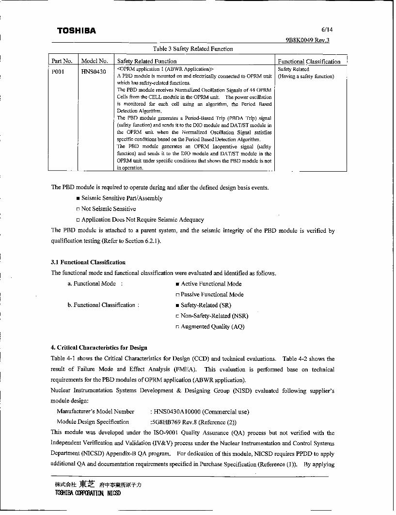
Table 3 Safety Related Function
Part No. Model No. Safety Related Function Functional Classification
Pol H540 <OPRM application 1 (ABWR Application)> Safety RelatedA PBD module is mounted on and electrically connected to OPRM unit (Having a safety function)which has safety-related functions.The PBD module receives Normalized Oscillation Signals of 44 OPRMCells from the CELL module in the OPRM unit. The power oscillationis monitored for each cell using an algorithm, the Period BasedDetection Algorithm.The PBD module generates a Period-Based Trip (PBDA Trip) signal(safety function) and sends it to the DIO module and DAT/ST module inthe OPRM unit when the Normalized Oscillation Signal satisfiesspecific conditions based on the Period Based Detection Algorithm.The PBD module generates an OPRM Inoperative signal (safetyfunction) and sends it to the DIO module and DAT/ST module in theOPRM unit under specific conditions that shows the PBD module is not
_________ __________in operation. _____________
The PBD module is required to operate during and after the defined design basis events.
* Seismic Sensitive Part/Assembly
o] Not Seismic Sensitive
o] Application Does Not Require Seismic Adequacy
The PBD module is attached to a parent system, and the seismic integrity of the PBD module is verified by
qualification testing (Refer to Section 6.2.1).
3.1 Functional Classification
The functional mode and functional classification were evaluated and identified as follows.
a. Functional Mode :* Active Functional Mode
o] Passive Functional Mode
b. Functional Classification : Safety-Related (SR)
o] Non-Safety-Related (NSR)
o] Augmented Quality (AQ)
4. Critical Characteristics for Design
Table 4-1 shows the Critical Characteristics for Design (CCD) and technical evaluations. Table 4-2 shows the
result of Failure Mode and Effect Analysis (FMEA). This evaluation is performed base on technical
requirements for the PBD modules of OPRM application (ABWR application).
Nuclear Instrumentation Systems Development & Designing Group (NISD) evaluated following supplier's
module design:
Manufacturer's Model Number ." NS0430A10000 (Commercial use)
Module Design Specification :5G8I-B769 Rev.8 (Reference (2))
This module was developed under the ISO-9001 Quality Assurance (QA) process but not verified with the
Independent Verification and Validation (IV&V) process under the Nuclear Instrumentation and Control Systems
Department (NICSD) Appendix-B QA program. For dedication of this module, NICSD requires PPDD to apply
additional QA and documentation requirements specified in Purchase Specification (Reference (1)). By applying
1U•I1B a ]IFATI•H NIC•D

TOSHIBA 7/149BSK0049 Rev.3
additional requirements based on the Purchase Specification (Reference (1)), manufacturer's model number ischanged to the following to distinguish the commercial use and US safety-related use. NISD also evaluated
following supplier's module design:
Manufacturer's Model NumberModule Design Specification
: HNS0430B00000 (US safety-related use): 5G8HC 106 Rev.1 (Reference (7))
Table 4-1 CCD and Technical Evaluation
Part No. [No [CCD ]Manufacturer's specification J Technical Evaluation
P00l I Physical Characteristics-DimensionSection 6 of purchase specification* 1(60.62W x 172.9H x 232.4D mam)Permissible deviations for dimensionsare specified in receiving inspectionspecification (Reference (5)).
-MassSection 6 of purchase specification* 1(550g or less)
Dimension is specified in Section 4.1.1of MDS*2 (60.6W x 172.9H x232.4Dmm )Mass is specified in Section 4.1.2 ofMvDS*2 (550g or less)
Manufacturer's item meets the purchaserrequirement.This characteristic does not directlycontribute to safety function. However,this characteristic related to itemcompatibility, form or fit is important whenconsidering replacement and Counterfeitand Fraudulent Items (CFI) issues.Mass is a factor which may affect seismiccapability of parent component.
2 Physical Characteristics Module configuration is described in Manufacturer's item meets the purchaser-General configuration and shape Section 4.1 of MDS*2 requirement.Module configuration and shape is This characteristic does not directlydescribed in Section 6 of purchase contribute to safety function. However,specification* 1 this characteristic related to item
compatibility, form or fit is important whenconsidering replacement and CFI issues.These characteristics contribute toEquipment Qualification (EQ) and EMC
___________________________ capability.3 Performance Characteristics Data transmission function is specified Manufacturer's item meets the purchaser
-Data transmission function in Sections 5.1 and 5.2 of MDS*2. requirement.Sections 5.2.3-1, and -2 of Unit DDS*3 Safety functions of the PBD module are This characteristic contributes to safetyspecifies data transmission functions of specified in Sections 6.1 through 6.1.6. function of parent component.safety related signals.
-Safety signal generating functionPBDA Trip and OPRM Inoperativesignal generation function (Safetyfunctions) specified in Section 5.2.3-3of Unit DDS*3.
4 Performance Characteristics Fault management functions are Manufacturer's item meets the purchaser-Fault Management and Diagnostics specified in Section 10 of MDS*2. requirement.
Sections 9 of Unit DDS*3 specifies WDT function is specified in Section This characteristic does not directlyfunctions of FPGA operation monitor 6.1.6 of MDS*2. contribute to safety function.(Watch Dog Timer (WDT)), and data Power on reset function is specified in However, the fallure of fault managementtransmission monitor. Section 9 of MDS*2. and diagnostic function may lead to fallureSection 5.2.3 -3 of Unit DDS*3 to detect malfunctions of item's safetyspecifies OPRM Alarm Judgment functions.Function.Section 8 of Unit DDS*3 specifiesinitializing processes (power on reset
____ function).5 Dependability FPGA modules that include FPGA logic
need special attention when indentifyingCCDs. Dependability becomessignificantly more important wheudedicating digital equipment. If there is aproblem in the FPGA logic that degradesthe dependability of a FPGA-basedmodule, it reflects a design error that wasbuilt into the FPGA-based module, or amismatch between the functionalrequirements and the FPGA-based moduledesign. The "'Dependability" is a CCD ofFPGA-based module.
*1 Purchase Specification, 5Q8K0021 Rev.3 (Reference (1))
*2 MIDS: Module Design Specification, 5G8HC106 Rev.1 (Reference (7))
*3 Unit DDS: Unit Detailed Design Specification, 5B8K0041 Rev.2 (Reference (3))

TOSHIBA 9B8K009 Rev.
9B8K0049 Rev.3
Table 4-2 Failure Mode and Effect AnalvsisNo. Function Failure Mode Failure Effect on System Method of Effect on Remarks
Mechanism Detection Plant_______________ Operation _____
Power on reset Fail on during Device failure All FPGAs in the PBD module will The "1INOP" One divisionfunction module halt. This failure can be detected indicator on the of APRMv
operating by WDT on the module. The PBD module (OPRM)PBD module generates "OPRM tumns on. InoperativeInoperative" signal.
Fail off when Device failure All FPGAs in the module will not This failure error Loss of oneinitializing restart (initialize) once it shuts will be detected division trip
down, with a function.surveillance test Unless theduring periodic OPRM unitinspection, is shut down,
it operates_______________________normally.
2 DC/DC Fail low Circuit failure All FPGAs in the PBD module will The "INOP" One divisionconverter halt. This failure can be detected indicator on the of APRM(+2.5V power by WDT on the module. The PBD module (OPRM)supply to PBD module generates "OPRM turns on. InoperativeFPGA) Inoperative" signal.
Fail high Circuit failure This failure may cause damage toFPGA device. ~
3 CELL signal Incorrect data Circuit failure The FPGA ( )) will The "INOP" One divisioninput processing input Contact failure detect a panity error or time out indicator on the of APRMfunction of middle-plane error. The PBD module generates PBD module (OPRM)
connector "OPRM Inoperative" sig~nal, turns on. InoperativeFPGA FPGA a,e This failure can be detected by The "INOP" One divisionoperation halt [( • WDT on the PBD module. The indicator on the of APRMv
tallure PBD module generates "OPRM PBD module (OPRM)Inoperative" signal. tumns on. Inoperative
4 Multiplexed Incorrect serial Circuit failure The "FARL" The displayserial data data output FPGA a,e The DAT/ST module will detect a indicator on the in mainoutput function • ) parity error. DAT/ST module control room(Output to failure The DAT/ST module generates turns on. indicatesDAT/ST "OPRM Minor Failure" signal. 'NMS'module) alarm.
5 PBDA Trip Fail on of Circuit failure The PBD module generates a The "TRIP" One divisionoutput function discreet output Contact failure spurious trip signal. indicator on the spurious trip(Output to DIO of middle-plane PHD module signalmodule) connector turns on.
FPGA a~e
failureFail off of Circuit failure Even if the PBDA Trip fails off, This failure error Nonediscreet output Contact failure the PBD module generates the will be detected
of middle-plane "Trip" signal. with aconnector Even if the "Trip" signal fails off, surveillance test
the PBD module generates the during periodicPBDA Trip signal. inspection.
(OPRM unit hasPBDA Trip testfunctions)
FPGA }a~ None This failure error Loss of one( iwill be detected division tripthilure with a function
surveillance testduring periodicinspection.(OPRM unit hasPBDA Trip testfunctions) _____
PBD A Tripjudgmentfunction
FPGAOperation halt
FPGA jDisconnectionsbetween mainand sub PCB
This failure can be detected byWDT on the PBD module. ThePBD module generates "OPRMInoperative" signal.
The "INOP"indicator on thePBD moduletumns on.
One divisionof APRM(OPRM)OInoperative
Incorrect tripjudgmentSRAM failure This failure can be detected by
SRAM error detection function inFPGAs. The PBD modulegenerates "OPRM Inoperative"signal.
The "INOP"indicator on thePBD moduletumns on.
One divisionof APRM(OPR.M)Inoperative
~I~± ~1U~IBA OJ~I~AT[U'L NI~J~

TOSHIBA 9/14
9B8K0049 Rev.3No. Function Failure Mode Failure Effect on System Method of Effect on Remarks
Mechanism Detection PlantOperation _____
7 Parameter Incorrect Rotary switch A spurious trip signal may he The setpoint This failurestorage function parameter on PCB failure generated. displayed on may lead to
A trip signal may not he generated PBD module will one divisionwhen necessary. he incorrect spurious trip
value. This signal or lossfailure error will of onehe detected with division tripa surveillance test function.during periodicinspection.
EEPROM This failure can he detected by The "INOP" One divisionfailure WDT or EEPROM error detection indicator on the of APRMFPGA a,c function on the PBD module. PBD module (OPRM)
The PBD module generates turns on. Inoperative________failure "OPRM Inoperative" sig~nal.
8 Fault Fail off WDT circuit None This failure error Loss of onemanagement failure will be detected division tripfunction Output circuit with a function(OPRM failure surveillance testInoperative FPGA a,e during periodicsignal, OPRM ( ) inspection.Minor Failure failuresignal) _____
Fail on WDT circuit The PBD module generates a A spurious One divisionfailure spurious "OPRM Inoperative" OPRM of APRMOutput circuit signal. Inoperative (OPRM)failure signal is InoperativeFPGA( a e generated.
___ tailureHMI-E ~ FPGA FPGA ac The PBD module detects HMIv The "FAIL" Operator can-HMI controller operation halt t( )a~ FPGA failure. The PBD module indicator on the not performFPGA failure generates "OPRM Minor Failure" PBD module front panel
signal. turns on. operations.The displayin maincontrol roomindicates'NMS'
alarm. __ __
10 HIMI Fail off (turn Device failure Numerical displays and LED This failure error None-Front panel oft) Circuit failure indicators turn off. will be detecteddisplay Cable with a
disconnection surveillance testduring periodic
______________ _____________inspection. _____
1 1 HIMI Fail on Device failure The PBD module goes into The "INOP" One division-Mode key Circuit failure "STANDBY" mode. The PBD indicator on the of APRMswitch Cable module generates "OPRMv PBD module (OPRM)
disconnection Inoperative" signal. tumns on. Inoperative_____________Fail off________ ______ ____
12 HMI Fail on Device failure None This failure error Operator can-Button Circuit failure will be detected not performswitches Cable with a front panel
disconnection surveillance test operations.during periodic One divisioninspection, of APRM
(OPRM)Inoperative
_____________Fail off ____________________________________________
5. Critical Characteristics for Acceptance, Verification Methods and Responsibilities
5.1 Verification of Physical and Performance Characteristics Depending on Supplier Testing
The physical characteristics and perfonnance characteristics are able to be measured as CCAs by the supplier
testing and Nuclear Instrumentation and Control Systems Department (NICSD) intends to receive Certificate of
Conformance (C of C) and the supplier's test record during the receiving inspection, the following supplier's
process to control CC shall be verified as CCAs, as a minimum, through Commercial Grade (CG) survey of
1OHIIB cXIfORATIIG NlIc}

TOSHIBA 10/149BXK0049 Rev_3
PPDD and receiving inspection.
*Design Control (Document Control)
*Inspection and Test Control
*Measuring and Test Equipment Control
To supplement verification of the general configuration and shape, supplier's control capability regarding
"Configuration Control and Traceability of Hardware" shall be verified through CG Survey of PPDD, evaluation
of sub-suppliers, and receiving inspection. Refer to Table 5-1.
5.2 Verification of "Dependability" of Module
To verify the dependability of modules, the following CCAs related to supplier's control capability of CC shall be
verified through CG survey of PPDD, evaluation of sub-suppliers, receiving inspection, oversight of design
review meeting, review of supplier documents, oversight of supplier testing, and witness of FPGA
implementation.
*Built-in Quality
*Configuration Control and Traceability of Software and Hardware
Refer to Table 5-1.
Table 5-1 CCA and Verification Method
Item Critical Characteristics Verification Method Responsibility Verification Method for ResponsibilityNo for Acceptance for Qualification Production________1 Physical Characteristics Receiving Inspection NICS-QC
-Dimension (Receiving C of C and-Mass supplier's test record, Section-General Configuration and 6.1. 1)Shape
2 Performance Receiving Inspection NICS-QCCharacteristics (Receiving C of C and-Data Transmission supplier's test record, SectionFunction 6.1.1)-Safety signal generating
function
-Fault Management and____Diagnostics
3 Design Control CG Survey of PPDD NICS-QA Receiving Inspection NICS-QC(Document Control) (Section 6.2.2) (Receiving C of C, Section
6.1.1)4 Inspection and Test CG Survey of PPDD NICS-QA Receiving Inspection NICS-QC
Control (Section 6.2.2) (Receiving C of C, Section
6.1.1)5 Measuring and Test CG Survey of PPDD NICS-QA Receiving Inspection NICS-QC
Equipment Control (Section 6.2.2) (Receiving C of C, Section
6.1.1)
6 Build in Quality CG Survey of PPDD NICS-QA Oversight of design review NICS-QC(Section 6.2.2) meeting
(Section 6.1.2)Review of supplier documents NICSD IV&V(Section 6.1.3) TeamOversight of supplier testing NICSD IV&V
____________________________(Section 6.1.4) Team
TOIINII (OflgWFAIG NIlt)

TOSH IBA 11/14__________________ ______________________9B8K0049 Rev.3
Item Critical Characteristics Verification Method Responsibility Verification Method for ResponsibilityNo -for Acceptance for Qualification _______Production ________
7 Configuration Control CG Survey of PPDD, NICS-QA Witness of FPGA NICS-QCand Traceability o f Evaluation of implementationSoftware and Hardware sub-suppliers (Section 6.1.5)________________________(Section 6.2.2) ______________________________
NICSD Nuclear Instrumentation and Control Systems Department
NICS-QA Quality Assurance Group for Nuclear Instrumentation & Control Systems
NICS-QC Quality Control Group for Nuclear Instrumentation & Control Systems
IV&V Independent Verification and Validation
6. Verification Instruction
6.1 Recurring Activities6.1.1 Receiving Inspection
Receiving inspectors or QC inspectors from NICS-QC shall implement the receiving inspection in
accordance with the "Receiving Inspection Procedure (Section 9-(1))" and the "Standard Receiving
Inspection Specification (Section 9-(2))." The verification results are recorded in the form of "Receiving
Inspection Check List/Report (Section 7-(1))."
6.1.2 Oversight of Design Review Meeting
NICSD shall perform oversight of Design Review (DR) meetings conducted by PPDD in accordance with
Section 9.1.1 of the Commercial Dedication Instruction (Reference (6)).
6.1.3 Review of Supplier Documents
NICSD shall perform review of supplier documents in accordance with Section 9.1.2 of the Commercial
Dedication Instruction (Reference (6)).
6.1.4 Oversight of Supplier Testing
NICSD shall perform oversight on FPGA Testing and Module Validation Testing conducted by PPDD
supplier documents in accordance with Section 9.1.3 of the Commercial Dedication Instruction (Reference
(6)).
6.1.5 Witness of FPGA Implementation
NICSD shall perform witness of the FPGA implementation work by TDMS in accordance with Section 9.1.4
of the Commercial Dedication Instruction (Reference (6)).
6.2 Periodic Activities
6.2.1 Environmental Conditions QualificationEquipment qualification testing and EMC qualification testing are performed in a type test using test
specimen. Successful completion and continued application of qualification testing verifies that the item is
capable of performing its intended safety function. Any time a design change is made to the item or item is
used in another application, impact on all previous qualification programs shall be evaluated to determine if
re-qualification is required.
IO3IIBA (JfPATII1 Nl~c•
TOSHIBA 12/149B8K0049 Rev.3
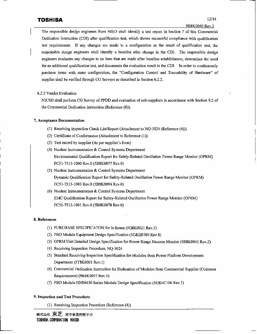
Theresponsible design engineers frmNISD salidentify a test report in Section 7 of this Commercial
Dedication Instruction (CDI) after qualification test, which shows successful compliance with qualification
test requirements. If any changes are made to a configuration as the result of qualification test, the
responsible design engineers shall identify a baseline after change in the CDI. The responsible design
engineers evaluates any changes to an item that are made after baseline establishment, determines the need
for an additional qualification test, and documents the evaluation result in the CDI. In order to continuously
purchaase items with same configuration, the "Configuration Control and Traceability of Hardware" of
supplier shall be verified through CG Surveys as described in Section 6.2.2.
6.2.2 Vendor Evaluation
NICSD shall perform CG Survey of PPDD and evaluation of sub-suppliers in accordance with Section 9.2 of
the Commercial Dedication Instruction (Reference (6)).
7. Acceptance Documentation
(1) Receiving Inspection Check List/Report (Attachment to NQ-3 024 (Reference (4)))
(2) Certificate of Conformance (Attachment to Reference (1))
(3) Test record by supplier (As per supplier's form)
(4) Nuclear Instrumentation & Control Systems Department
Environmental Qualification Report for Safety-Related Oscillation Power Range Monitor (OPRM)
FC51-7513-1000 Rev.0 (5B 8K0077 Rev.0)
(5) Nuclear Instrumentation & Control Systems Department
Dynamic Qualification Report for Safety-Related Oscillation Power Range Monitor (OPRM)
FC51-7513 -1003 Rev.0 (5B 8K0094 Rev.0)
(6) Nuclear Instrumentation & Control Systems Department
EMC Qualification Report for Safety-Related Oscillation Power Range Monitor (OPRM)
FC5 1-7513-1001 Rev.0 (5B8K0078 Rev.0)
8. References
(1) PURCHASE SPECIFICATON for in-house (5Q8K0021 Rev.3)
(2) PBD Module Equipment Design Specification (5G8I-B769 Rev.8)
(3) OPRM Unit Detailed Design Specification for Power Range Neutron Monitor (5B8K0041 Rev.2)
(4) Receiving Inspection Procedure, NQ-3 024
(5) Standard Receiving Inspection Specification for Modules from Power Platform Development
Department (5T8K0001 Rev. 1)
(6) Commercial Dedication Instruction for Dedication of Modules from Commercial Supplier (Common
Requirements) (9B8K0057 Rev. 1)
(7) PBD Module HNS0430 Series Module Design Specification (5G8HC 106 Rev.1)
9. Inspection and Test Procedure
(1) Receiving Inspection Procedure (Reference (4))
TUI•IBA OX T[TIL NICSD

TOSHIBA 13/14
9B8K0049 Rev.3
(2) Standard Receiving Inspection Specification (Reference (5))
10. Supplements
N/A

TOSHIBA I 4E
QRRKOO4Q Rev ~
"• • •E • REVISIONS
REV.MAR ,•••• •, ' •• •• B PAGE
REV. ISSAGDULCEADEDTET APPROVED BY REV IEW'ED BY PREPARED BY REGISTERED3, 4, 7, For detailed changed contents and impact evaluation, refer to
S 12 DECN-9B8K0049-01 RevO.0
K. Wakita T. Taruini T. Funusawa H. Ito.ta]. 17, 2012 Jul. 17, 2012 Jult. 17, 2012 Jul. 17, 2012
Jul. 17, 2012
For detailed changed contents and impact evaluation, refer toQ ~DECN-9BSK0049-02 RevO.0
K.Wakitu T. Taruni T. Furusawa K. TarnuraAug.22, 2012 Aug.20, 2012 Aug.20. 2012 Aug22, 2012
Aug22, 20 2
For detailed changed contents and impact evaluation, refer toQ EN980490 eO 4wso