Embed Size (px)
Citation preview
Commercial Marketing Operations• CDMA Portfolio Overview
Tom Jackson
CDMA Commercial Marketing
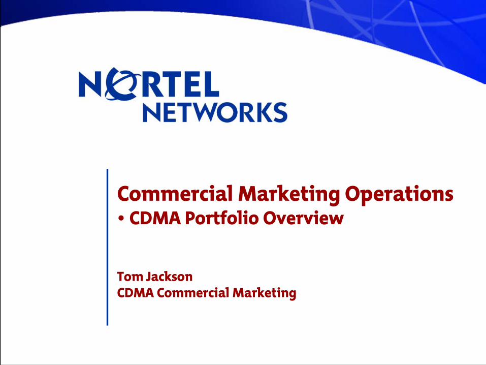
CDMA Wireless Network
Mobile Telephone Switching Center(MTSO)
CDMA Base Station Controller CDMA
Cell Sites
DMS-MTX
Base station Manager
PSTN,Local Carrier, Long Distance
Carriers
CDMA Wireless System Architecture
T1T1T1
100BaseT
2
CDMA LC-
Process Overview
3
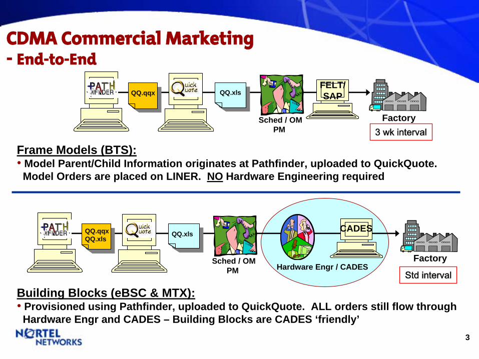
CDMA Commercial Marketing-
End-to-End
Frame Models (BTS):•
Model Parent/Child Information originates at Pathfinder, uploaded to QuickQuote. Model Orders are placed on LINER. NO Hardware Engineering required
QQ.qqx QQ.xlsFELT/SAP
Sched / OM PM
Factory
QQ.qqxQQ.xls
QQ.xls
Sched / OM PM
Factory
CADES
Hardware Engr / CADES
Building Blocks (eBSC & MTX):•
Provisioned using Pathfinder, uploaded to QuickQuote. ALL orders still flow through Hardware Engr and CADES – Building Blocks are CADES ‘friendly’
3 wk interval
Std interval
4
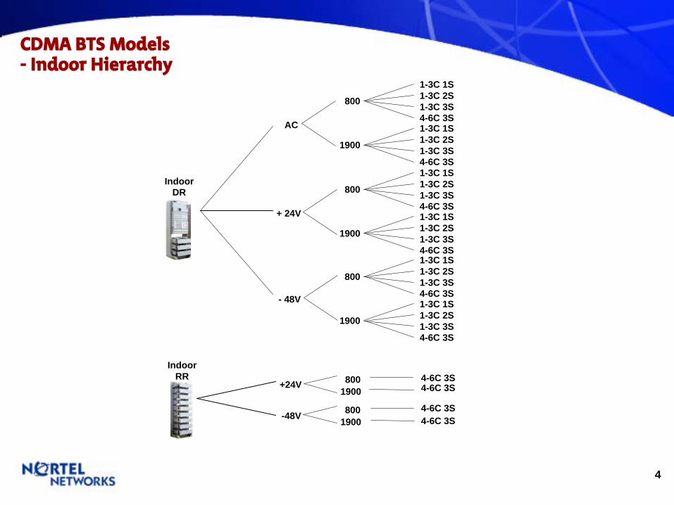
CDMA BTS Models
-
Indoor Hierarchy
IndoorDR
800
8001900
IndoorRR 4-6C 3S
4-6C 3S+24V
8001900
4-6C 3S4-6C 3S-48V
1-3C 1S1-3C 2S1-3C 3S4-6C 3S
AC
+ 24V
- 48V
1900
1-3C 1S1-3C 2S1-3C 3S4-6C 3S
800
1-3C 1S1-3C 2S1-3C 3S4-6C 3S
1900
1-3C 1S1-3C 2S1-3C 3S4-6C 3S
800
1-3C 1S1-3C 2S1-3C 3S4-6C 3S
1900
1-3C 1S1-3C 2S1-3C 3S4-6C 3S

5
OutdoorDE
OutdoorRE
CDMA BTS Models
-
Outdoor Hierarchy
800
1-3C 1S1-3C 2S1-3C 3S4-6C 3S
AC
1900
1-3C 1S1-3C 2S1-3C 3S4-6C 3S
800
1-3C 1S1-3C 2S1-3C 3S4-6C 3S
AC
1900
1-3C 1S1-3C 2S1-3C 3S4-6C 3S
6
CMO
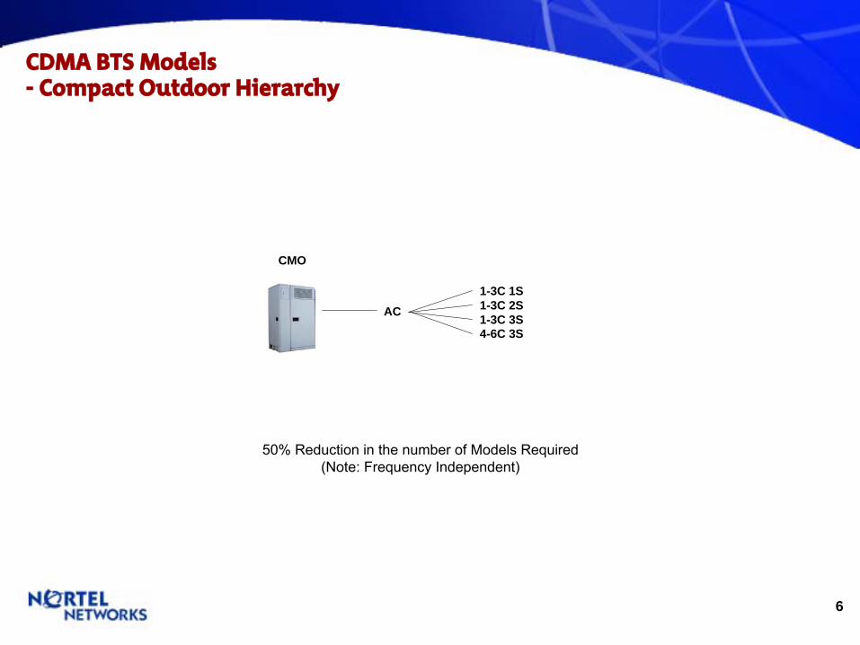
CDMA BTS Models
-
Compact Outdoor Hierarchy
AC
50% Reduction in the number of Models Required(Note: Frequency Independent)
1-3C 1S1-3C 2S1-3C 3S4-6C 3S

7
CMI
CDMA BTS Models
-
Compact Indoor Hierarchy
~66% Reduction in the numbers of Models Required(Note: Frequency Independent –
Shelf equals a Cell site)
3’ 1-3C 1-3S
AC
24 / - 48Vdc
5’1-3C 1-3S4-6C 1-3S
7’1-3C 1-3S4-6C 1-3S
3’ 1-3C 1-3S
5’1-3C 1-3S4-6C 1-3S
7’1-3C 1-3S4-6C 1-3S
8
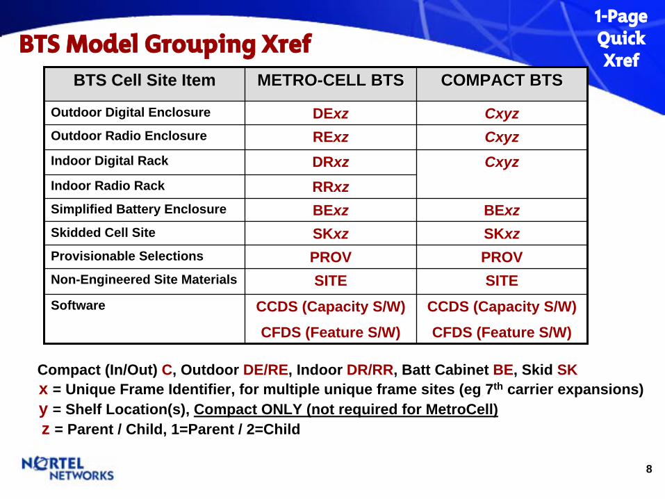
BTS Model Grouping XrefBTS Cell Site Item METROMETRO--CELL BTSCELL BTS COMPACT BTSCOMPACT BTS
Outdoor Digital Enclosure DExz CxyzOutdoor Radio Enclosure RExz CxyzIndoor Digital Rack DRxz CxyzIndoor Radio Rack RRxzSimplified Battery Enclosure BExz BExzSkidded Cell Site SKxz SKxzProvisionable Selections PROV PROVNon-Engineered Site Materials SITE SITESoftware CCDS (Capacity S/W)
CFDS (Feature S/W)
CCDS (Capacity S/W)
CFDS (Feature S/W)
Compact (In/Out) C, Outdoor DE/RE, Indoor DR/RR, Batt Cabinet BE, Skid SKx = Unique Frame Identifier, for multiple unique frame sites (eg 7th carrier expansions) y = Shelf Location(s), Compact ONLY (not required for MetroCell) z = Parent / Child, 1=Parent / 2=Child
1-PageQuickXref

9
CDMA BTS Model Methodology
Frame Frame ModelsModels--Metro IndoorMetro Indoor--Metro OutdoorMetro Outdoor
RequiredRequired SelectionsSelections--Required Options Required Options
Site MaterialSite Material-- Non EngineeredNon Engineered
• Models are Frame level•
Metro Based Frames include Radios (FRM/MFRM/MFRM2)
• Also includes Cabling• Also includes Filler Plates• Also includes Rectifiers
• BTS Assoc Items• GPS Cables• Mounting Kits• Defined IRM Kits•
T1/E1&Alarm Cables•
Misc Connectorized Cables
•
Hi volume – typically BTS associated
• Power / Gnd Cables•
Unique & Specific Site Requirement
•
Lo volume – typically MTX associated
Note: These items require advance site specific knowledge. - Not in the Eng Guides - Mat’l identified by I&C
Provisioned Provisioned SelectionsSelections--Selected BTS H/WSelected BTS H/W
• CEM Cards• Duplexors• GPS Antenna• RM (for CMI)• Batteries
Note:- ReqSel make the
Models flexible - Some Required
Selections can also be PROV (for sparing, etc)
Models are NOT unique

10
CDMA Network Portfolio- Overview
11
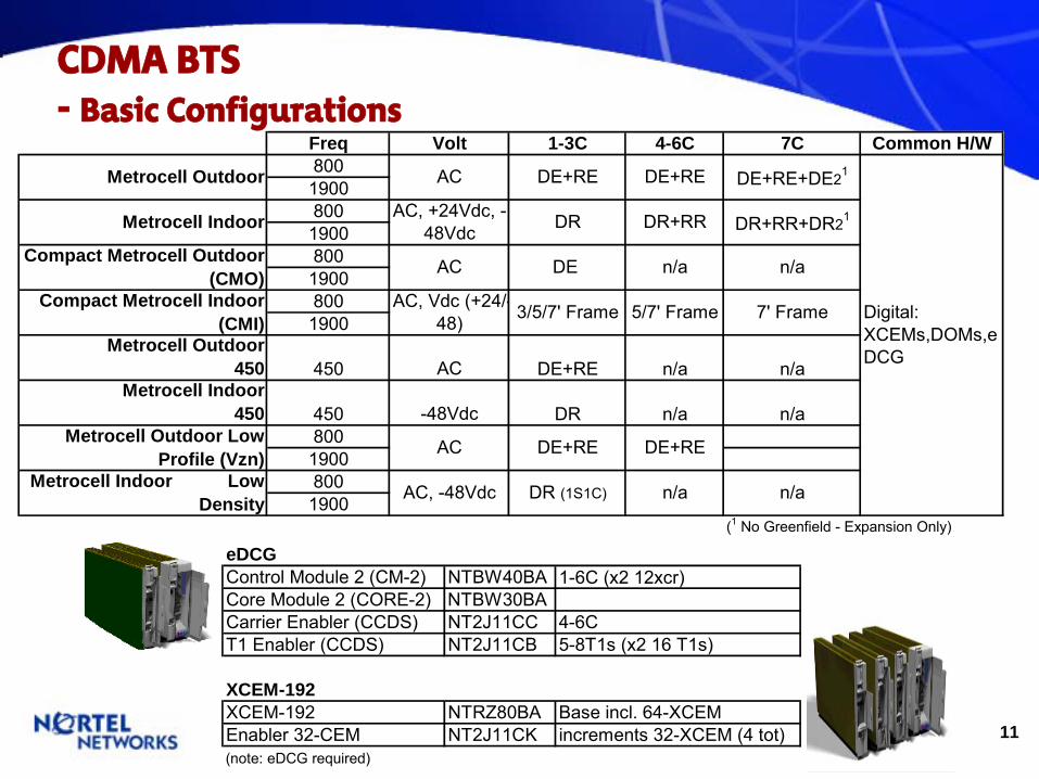
CDMA BTS-
Basic Configurations
eDCGControl Module 2 (CM-2) NTBW40BA 1-6C (x2 12xcr)Core Module 2 (CORE-2) NTBW30BACarrier Enabler (CCDS) NT2J11CC 4-6CT1 Enabler (CCDS) NT2J11CB 5-8T1s (x2 16 T1s)
XCEM-192XCEM-192 NTRZ80BA Base incl. 64-XCEMEnabler 32-CEM NT2J11CK increments 32-XCEM (4 tot)(note: eDCG required)
Freq Volt 1-3C 4-6C 7C Common H/W8001900800190080019008001900
Metrocell Outdoor 450 450 AC DE+RE n/a n/a
Metrocell Indoor 450 450 -48Vdc DR n/a n/a
80019008001900
(1 No Greenfield - Expansion Only)
n/a
Digital: XCEMs,DOMs,eDCG
n/a
DE+RE
DE+RE
DE+RE+DE21
DR+RR+DR21
n/a
7' Frame
DE+RE
DR (1S1C)
DR+RR
5/7' Frame
n/a
DE+RE
DR
DE
3/5/7' Frame
AC, -48Vdc
AC, +24Vdc, -48Vdc
Metrocell Outdoor
Metrocell Indoor
AC
AC
AC, Vdc (+24/-48)
AC
Compact Metrocell Outdoor (CMO)
Compact Metrocell Indoor (CMI)
Metrocell Outdoor Low Profile (Vzn)
Metrocell Indoor Low Density
12
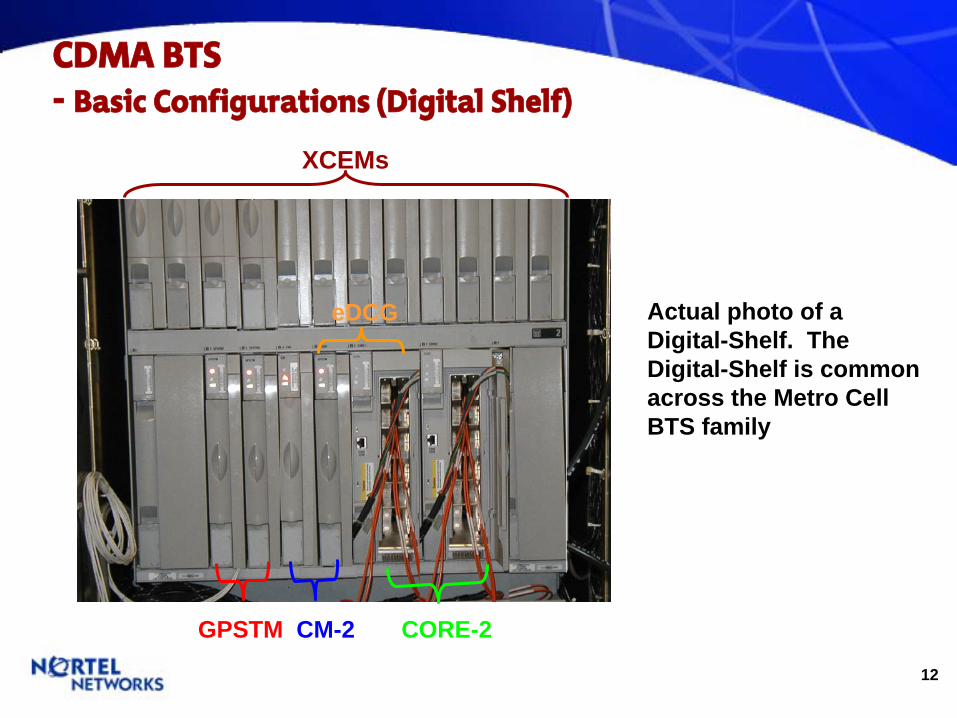
CDMA BTS-
Basic Configurations (Digital Shelf)
eDCG
XCEMs
GPSTM CM-2 CORE-2
Actual photo of a Digital-Shelf. The Digital-Shelf is common across the Metro Cell BTS family

13
CDMA BTS- Metrocell Power
RRRR
Ex: Metrocell Indoor
DRDR
~ A/C24Vdc
-48VdcLine In
Note (DR):ONLY A/C Sites have Rectifiers (A/C-D/C).
Note (RR):Native voltage is -48Vdc (most everything today is ‘Dual Band’
-
48/24Vdc).Thus a DR Model can be A/C with the RR Model being DC
-48Vdc (Native Voltage)
Power
14
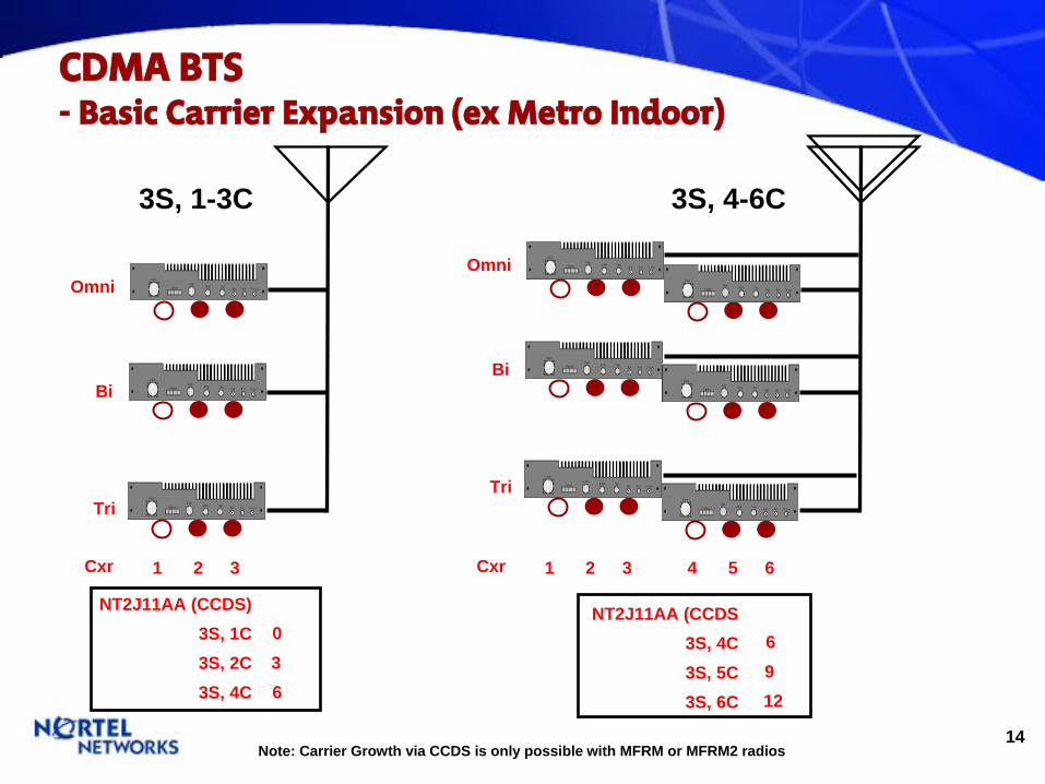
CDMA BTS-
Basic Carrier Expansion (ex Metro Indoor)
3S, 1-3C
Bi
Omni
Tri
Cxr 1 2 3
NT2J11AA (CCDS)3S, 1C3S, 2C3S, 4C
036
3S, 4-6C
Bi
Omni
Tri
Cxr 1 2 3
NT2J11AA (CCDS3S, 4C3S, 5C3S, 6C
6912
4 5 6
Note: Carrier Growth via CCDS is only possible with MFRM or MFRM2 radios
15
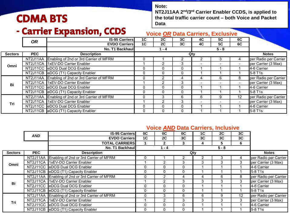
CDMA BTS-
Carrier Expansion, CCDS
IS-95 Carriers 1C 2C 3C 4C 5C 6CEVDO Carriers 1C 2C 3C 4C 5C 6C
No. T1 Backhaul 1 - 4 5 - 8Sectors PEC Description Qty Notes
NT2J11AA Enabling of 2nd or 3rd Carrier of MFRM 0 1 2 2 3 4 per Radio per CarrierNT2J11CA 1xEV-DO Carrier Enabler 1 2 3 - - - per Carrier (3 Max)NT2J11CC eDCG Dual DCG Enabler 0 0 0 1 1 1 4-6 CarrierNT2J11CB eDCG (T1) Capacity Enabler 0 0 0 1 1 1 5-8 T1sNT2J11AA Enabling of 2nd or 3rd Carrier of MFRM 0 2 4 4 6 8 per Radio per CarrierNT2J11CA 1xEV-DO Carrier Enabler 1 2 3 - - - per Carrier (3 Max)NT2J11CC eDCG Dual DCG Enabler 0 0 0 1 1 1 4-6 CarrierNT2J11CB eDCG (T1) Capacity Enabler 0 0 0 1 1 1 5-8 T1sNT2J11AA Enabling of 2nd or 3rd Carrier of MFRM 0 3 6 6 9 12 per Radio per CarrierNT2J11CA 1xEV-DO Carrier Enabler 1 2 3 - - - per Carrier (3 Max)NT2J11CC eDCG Dual DCG Enabler 0 0 0 1 1 1 4-6 CarrierNT2J11CB eDCG (T1) Capacity Enabler 0 0 0 1 1 1 5-8 T1s
OR
Omni
Tri
Bi
IS-95 Carriers 0C 0C 0C 1C 2C 3CEVDO Carriers 1C 2C 3C 3C 3C 3C
TOTAL CARRIERS 1 2 3 4 5 6No. T1 Backhaul 1 - 4 5 - 8
Sectors PEC Description Qty NotesNT2J11AA Enabling of 2nd or 3rd Carrier of MFRM 0 1 2 2 3 4 per Radio per CarrierNT2J11CA 1xEV-DO Carrier Enabler 1 2 3 3 3 3 per Carrier (3 Max)NT2J11CC eDCG Dual DCG Enabler 0 0 0 1 1 1 4-6 CarrierNT2J11CB eDCG (T1) Capacity Enabler 0 0 0 1 1 1 5-8 T1sNT2J11AA Enabling of 2nd or 3rd Carrier of MFRM 0 2 4 4 6 8 per Radio per CarrierNT2J11CA 1xEV-DO Carrier Enabler 1 2 3 3 3 3 per Carrier (3 Max)NT2J11CC eDCG Dual DCG Enabler 0 0 0 1 1 1 4-6 CarrierNT2J11CB eDCG (T1) Capacity Enabler 0 0 0 1 1 1 5-8 T1sNT2J11AA Enabling of 2nd or 3rd Carrier of MFRM 0 3 6 6 9 12 per Radio per CarrierNT2J11CA 1xEV-DO Carrier Enabler 1 2 3 3 3 3 per Carrier (3 Max)NT2J11CC eDCG Dual DCG Enabler 0 0 0 1 1 1 4-6 CarrierNT2J11CB eDCG (T1) Capacity Enabler 0 0 0 1 1 1 5-8 T1s
AND
Omni
Bi
Tri
Voice OROR Data Carriers, Exclusive
Voice ANDAND Data Carriers, Inclusive
Note: NT2J11AA 2nd/3rd Carrier Enabler CCDS, is applied to the total traffic carrier count – both Voice and Packet Data
16
CDMA BTS-
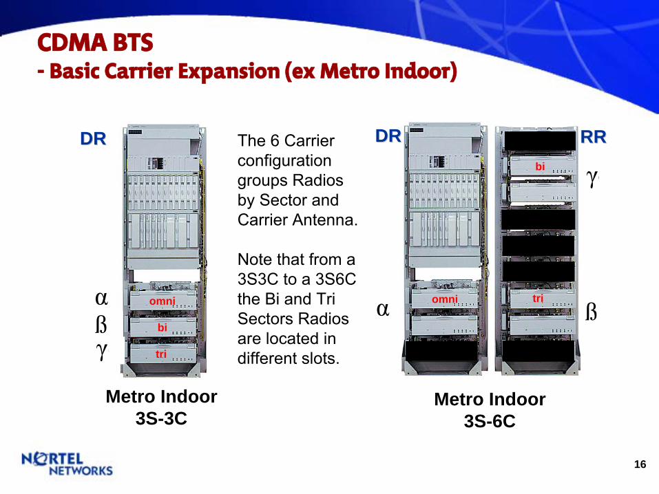
Basic Carrier Expansion (ex Metro Indoor)
Metro Indoor3S-3C
αdßdγd
DRDR
αd ßd
γdDRDR RRRR
Metro Indoor3S-6C
omni
bi
triomni
bi
tri
The 6 Carrier configuration groups Radios by Sector and Carrier Antenna.
Note that from a 3S3C to a 3S6C the Bi and Tri Sectors Radios are located in different slots.

17
CDMA BTS-
F7 Carrier Expansion (ex Metro Indoor)
MFRM2
•RR01 •DR11•DR01
MFRM2
MFRM2
MFRM
MFRM
MFRM
MFRM
MFRM2
MFRM
MFRM
•MFRM Feeds
MFRM2
MFRM2
MFRM2
MFRM2
MFRM2
MFRM2
Metro Indoor3S, 7C
9 MFRM2
7th
Carrier Growth
•NO ’Greenfields’•Only via Expansion•Example
3S,6C to 3S,7C
Add 3 MFRM2
Add n XCEMS
Add ‘Empty’
Frame•Empty Frame Models do exist for DE and DR. They include; Frame+Digital, less Radios•PF/QQ will denote the 2nd
DR frame as DR11 and children as DR12
The 2nd
Digital Frame is required for a 3rd
DCG or 2nd
eDCG as well as more XCEMs (>12)
18
CDMA BTS-
Carrier Growth Provisioning (ex Metro Indoor)
DRDR
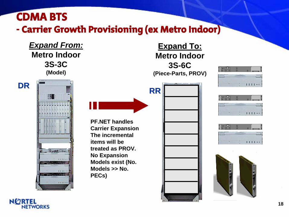
Expand From:Metro Indoor
3S-3C(Model)
Expand To:Expand To:Metro Indoor
3S-6C(Piece-Parts, PROV)
RRRR
PF.NET handles Carrier Expansion The incremental items will be treated as PROV.No Expansion Models exist (No. Models >> No. PECs)
19
CDMA BTS-
Carrier Frequency: 450 v 850 v 1900 MHz
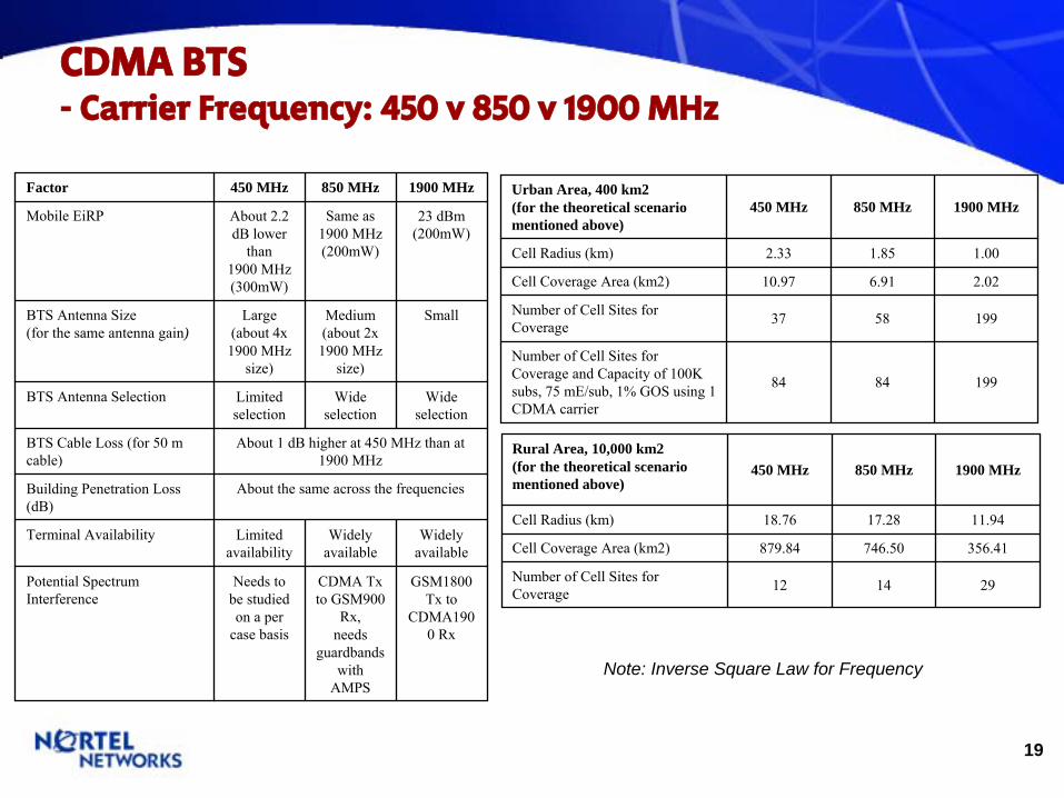
Note: Inverse Square Law for Frequency
Factor 450 MHz 850 MHz 1900 MHz
Mobile EiRP About 2.2 dB lower
than 1900 MHz(300mW)
Same as 1900 MHz(200mW)
23 dBm(200mW)
BTS Antenna Size(for the same antenna gain)
Large(about 4x 1900 MHz
size)
Medium(about 2x 1900 MHz
size)
Small
BTS Antenna Selection Limited selection
Wide selection
Wide selection
BTS Cable Loss (for 50 m cable)
About 1 dB higher at 450 MHz than at 1900 MHz
Building Penetration Loss (dB)
About the same across the frequencies
Terminal Availability Limited availability
Widely available
Widely available
Potential Spectrum Interference
Needs to be studied on a per
case basis
CDMA Tx
to GSM900 Rx,
needs guardbands
with AMPS
GSM1800 Tx
to CDMA190
0 Rx
Urban Area, 400 km2(for the theoretical scenario mentioned above)
450 MHz 850 MHz 1900 MHz
Cell Radius (km) 2.33 1.85 1.00
Cell Coverage Area (km2) 10.97 6.91 2.02
Number of Cell Sites for Coverage 37 58 199
Number of Cell Sites for Coverage and Capacity of 100K subs, 75 mE/sub, 1% GOS using 1 CDMA carrier
84 84 199
Rural Area, 10,000 km2(for the theoretical scenario mentioned above)
450 MHz 850 MHz 1900 MHz
Cell Radius (km) 18.76 17.28 11.94
Cell Coverage Area (km2) 879.84 746.50 356.41
Number of Cell Sites for Coverage 12 14 29
20
FCC Spectrum Allocation-
800MHz and 1900MHz
-
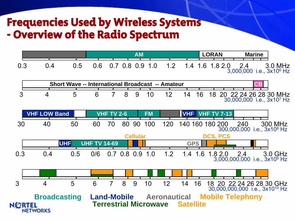
3 4 5 6 7 8 9 10 12 14 16 18 20 22 24 26 28 30 GHz30,000,000,000 i.e., 3x10¹⁰
HzBroadcasting Land-Mobile Aeronautical Mobile Telephony
Terrestrial Microwave Satellite
0.3 0.4 0.5 0/6 0.7 0.8 0.9 1.0 1.2 1.4 1.6 1.8 2.0 2.4 3.0 GHz3,000,000,000 i.e., 3x10⁹
Hz
UHF TV 14-69UHF GPSDCS, PCSCellular
0.3 0.4 0.5 0.6 0.7 0.8 0.9 1.0 1.2 1.4 1.6 1.8 2.0 2.4 3.0 MHz3,000,000 i.e., 3x10⁶
Hz
AM LORAN Marine
3 4 5 6 7 8 9 10 12 14 16 18 20 22 24 26 28 30 MHz30,000,000 i.e., 3x10⁷
Hz
Short Wave -- International Broadcast -- Amateur CB
30 40 50 60 70 80 90 100 120 140 160 180 200 240 300 MHz300,000,000 i.e., 3x10⁸
Hz
FM VHF TV 7-13VHF LOW Band VHFVHF TV 2-6
Frequencies Used by Wireless Systems -
Overview of the Radio Spectrum
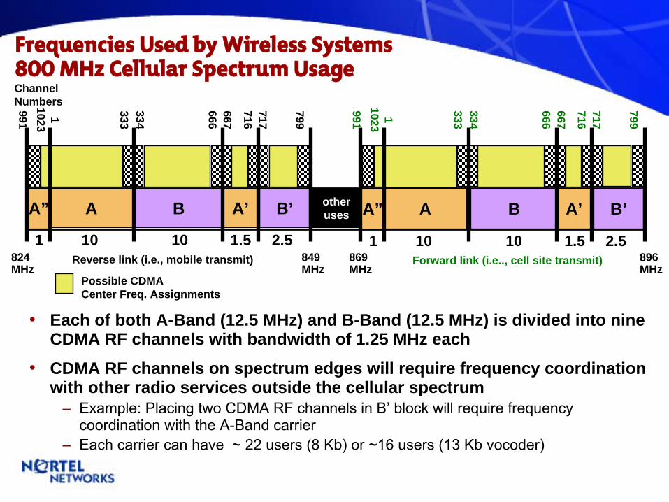
Frequencies Used by Wireless Systems 800 MHz Cellular Spectrum Usage
•
Each of both A-Band (12.5 MHz) and B-Band (12.5 MHz) is divided into nine CDMA RF channels with bandwidth of 1.25 MHz each
•
CDMA RF channels on spectrum edges will require frequency coordination with other radio services outside the cellular spectrum
–
Example: Placing two CDMA RF channels in B’
block will require frequency coordination with the A-Band carrier
–
Each carrier can have ~ 22 users (8 Kb) or ~16 users (13 Kb vocoder)
Possible CDMA Center Freq. Assignments
Channel Numbers
Forward link (i.e.., cell site transmit)Reverse link (i.e., mobile transmit)824MHz
849MHz
869MHz
896MHz
otherusesA” A”A B A’ B’
1 10 10 1.5 2.5
A B A’ B’
1 10 10 1.5 2.5
9911023
1 333334
666667
716717
799
9911023
1 333334
666667
716717
799
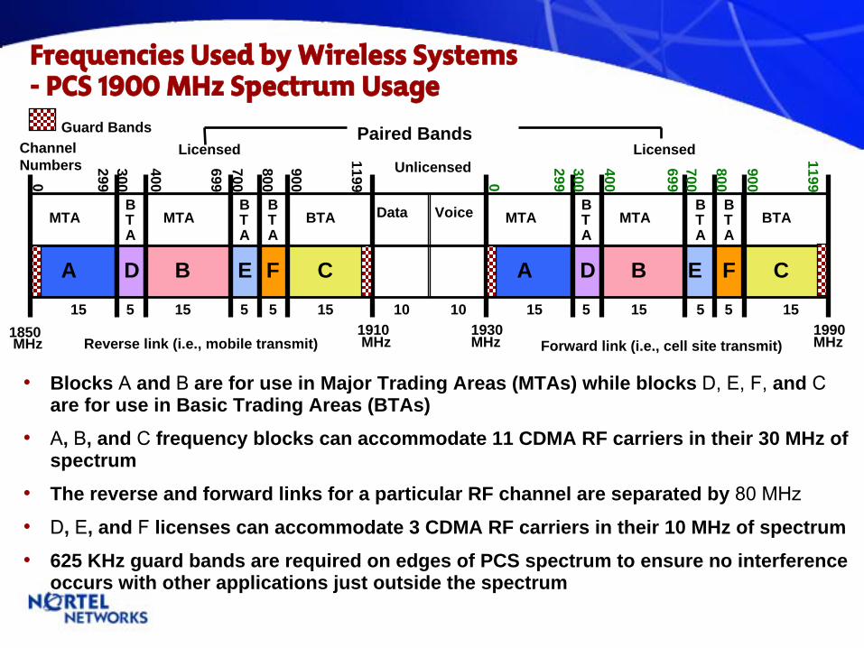
Frequencies Used by Wireless Systems -
PCS 1900 MHz Spectrum Usage
•
Blocks A and B are for use in Major Trading Areas (MTAs) while blocks D, E, F, and C
are for use in Basic Trading Areas (BTAs)
•
A, B, and C
frequency blocks can accommodate 11 CDMA RF carriers in their 30 MHz of spectrum
•
The reverse and forward links for a particular RF channel are separated by 80 MHz
•
D, E, and F
licenses can accommodate 3 CDMA RF carriers in their 10 MHz of spectrum
•
625 KHz guard bands are required on edges of PCS spectrum to ensure no interference occurs with other applications just outside the spectrum
Guard Bands
Forward link (i.e., cell site transmit)Reverse link (i.e., mobile transmit)1850MHz
BTA
BTA
BTA
BTA
BTA
BTA
Paired Bands
MTA BTAMTABTA MTAMTA
1910MHz
1930MHz
1990MHz
Data Voice
A D B E F C A D B E F C15 51010 1515151515 555 55
Licensed LicensedUnlicensed
0
Channel Numbers 299
300
400
699700
800
900
1199 0
299300
400
699700
800
900
1199
24
CDMA Network Topology-
Product Description / Evolution
25
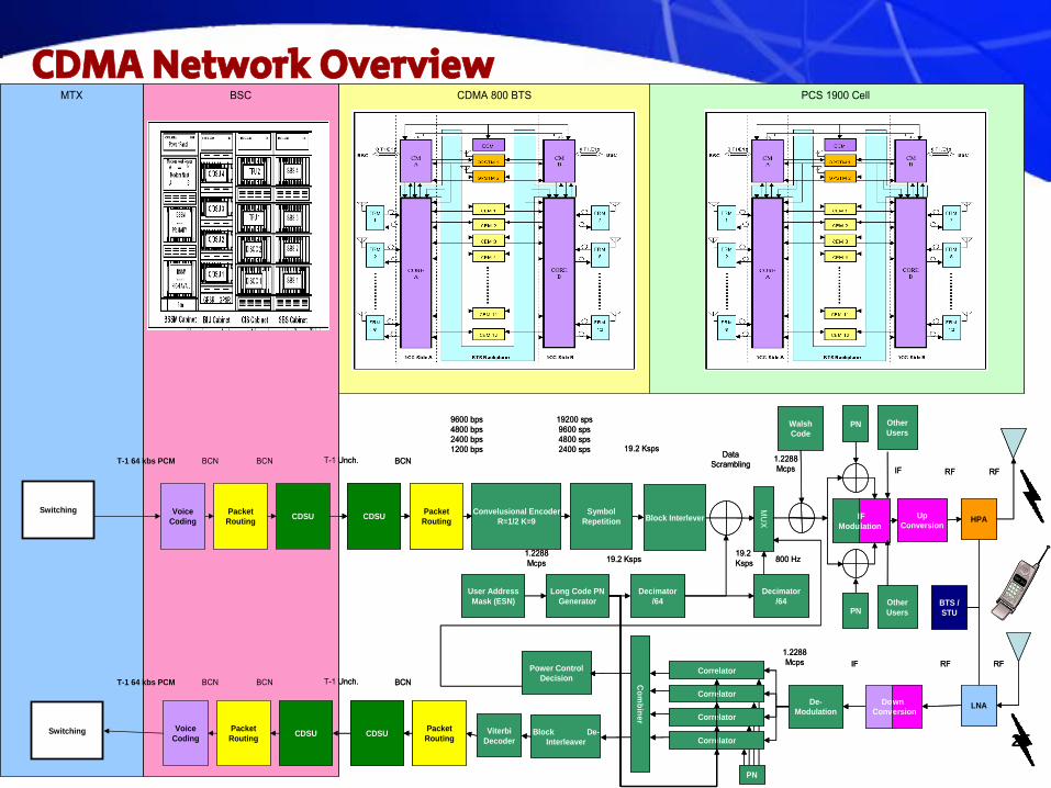
CDMA Network OverviewPCS 1900 Cell CDMA 800 BTSBSCMTX
Switching
Switching
Voice Coding
Voice Coding
Packet Routing
Packet Routing
CDSU
CDSU
CDSU
CDSU
T-1 64 kbs PCM BCN BCN
Packet Routing
Packet Routing
Convelusional Encoder R=1/2 K=9
Symbol Repetition Block Interlever
MU
X
Walsh Code
PN
F lation
I Modu
Up Conversion
HPA
Other Users
User Address Mask (ESN)
Long Code PN Generator
Decimator /64
Decimator /64
PNOther Users
BTS / STU
Power Control Decision
Correlator
Com
biner
Viterbi Decoder
Block De-Interleaver
Correlator
Correlator
Correlator
PN
De-Modulation
wn ersion
Do Conv
LNA
T-1 Unch. BCN
T-1 64 kbs PCM BCN BCN T-1 Unch. BCN
9600 bps4800 bps2400 bps1200 bps
19200 sps9600 sps4800 sps2400 sps 19.2 Ksps
Data Scrambling
19.2 Ksps
1.2288 Mcps IF RF RF
800 Hz
RF RFIF1.2288 Mcps
19.2 Ksps1.2288 Mcps
PCS 1900 Cell CDMA 800 BTSBSCMTX
Switching
Switching
Voice Coding
Voice Coding
Packet Routing
Packet Routing
CDSU
CDSU
CDSU
CDSU
T-1 64 kbs PCM BCN BCN
Packet Routing
Packet Routing
Convelusional Encoder R=1/2 K=9
Symbol Repetition Block Interlever
MU
X
Walsh Code
PN
F lation
I Modu
Up Conversion
HPA
Other Users
User Address Mask (ESN)
Long Code PN Generator
Decimator /64
Decimator /64
PNOther Users
BTS / STU
Power Control Decision
Correlator
Com
biner
Viterbi Decoder
Block De-Interleaver
Correlator
Correlator
Correlator
PN
De-Modulation
wn ersion
Do Conv
LNA
T-1 Unch. BCN
T-1 64 kbs PCM BCN BCN T-1 Unch. BCN
9600 bps4800 bps2400 bps1200 bps
19200 sps9600 sps4800 sps2400 sps 19.2 Ksps
Data Scrambling
19.2 Ksps
1.2288 Mcps IF RF RF
800 Hz
RF RFIF1.2288 Mcps
19.2 Ksps1.2288 Mcps

26
DMS-MTX Building Blocks
DMSDMS--CoreCoreXA CoreXA Core
MTXMTX
ENETENETENETMS
MessageSwitch
MSMSMessageMessageSwitchSwitch
BSMBTS
BTS
BTS
CIS
BSCBSC
CDMA2000 1XCDMA2000 1XEV-DOCDMAOne, IS-95
LPPLPP
CIU
CIU
CIU RMU
CAU
CAU
T1
DMSDMS--MTXMTX
CDMA BSSCDMA BSS
IOMIOMIOM
CallP
OA&M
NetworkingIS41
Billing
VLR
HLR
Mobility
LPPLPP
CAVU
XLIU
DTCDTCDTC
DTCDTCDTCCBRSCBRS
SPMSPMSPMMTX11/NBSS11.0MTX11/NBSS11.0
SBS
SBS
DTCDTCDTCDTCDTCDTCDTCDTCDTCSPMSPMSPM
CIS
CBRSCBRS
PSTNDTCDTCDTCPTS
SMDITo V-Mail
NEW NEW CDMA BSSCDMA BSS
IWFIWFIWF EIUT1 10/100 10/100
PDN
LIUANSI41ISUP/CSS7
SPMSPMSPMT1
T1,FRT1
DS30
DS512DS512/DS30
DS512/DS30
DS30
UnCh T1
OC-3ATM
T1
EDSPMEDSPM
DRU
DRU
ICP
Mobility
CallPICRM
TCHTCHMuxMux
E1/T1AMPS/TDMA (3:1)
TDMATDMA

27BSC
SBS
Power control
Soft Handoff
Voice Coding
CIS
Packet Routing
BSS Manager
OA&M for BSC and BTS
IS95/1xAir Interface
Softer HO
BTS
DTC
Trunking
CM / Other MTX Subsystems
HLR
VLR
Billing
Features & Services
Call Processing
Logs
Alarms
LPP
Resource Mgmt.
Inter-Switch Handoff(IS-41C)
PSTN Signalling
Pagingand
Access
LPP
OMs
PSTN or otherMobile Switch
Power Control
Selection
PCF PDSNPDSNINTERNET
IWFIWF
BIUBIU
DMS-MTX Building Blocks -
Functional Overview

28
Today’s CDMA Network -
Today’s 2G Voice Network
DMS MTX
Master O
scillatorSite M
anager
Main / Diversity Main / Diversity
Main / Diversity Main / DiversityMain / Diversity Main / Diversity
Main / Diversity Main / Diversity
Main / Diversity Main / DiversityMain / Diversity Main / Diversity
Spectrum In Net
work Tx
out
Router
Router
BT
S Control
BT
S Control
Radio Ports
Radio Ports
Power Distribution
WBDWBDWBDUWC-136HS (E-3)
Duplexers
Power Amplifiers
Spectrum In Net
work Tx
outIS-136 (T-24)
Spectrum In Net
work Tx
outWB-CDMA
WCDMASpectrum In Net
workLocation Services
BTS
BSC
BSS Manager NBSS 9.0
MAP/SDM
Voice
DMS HLR
MTX 09
29
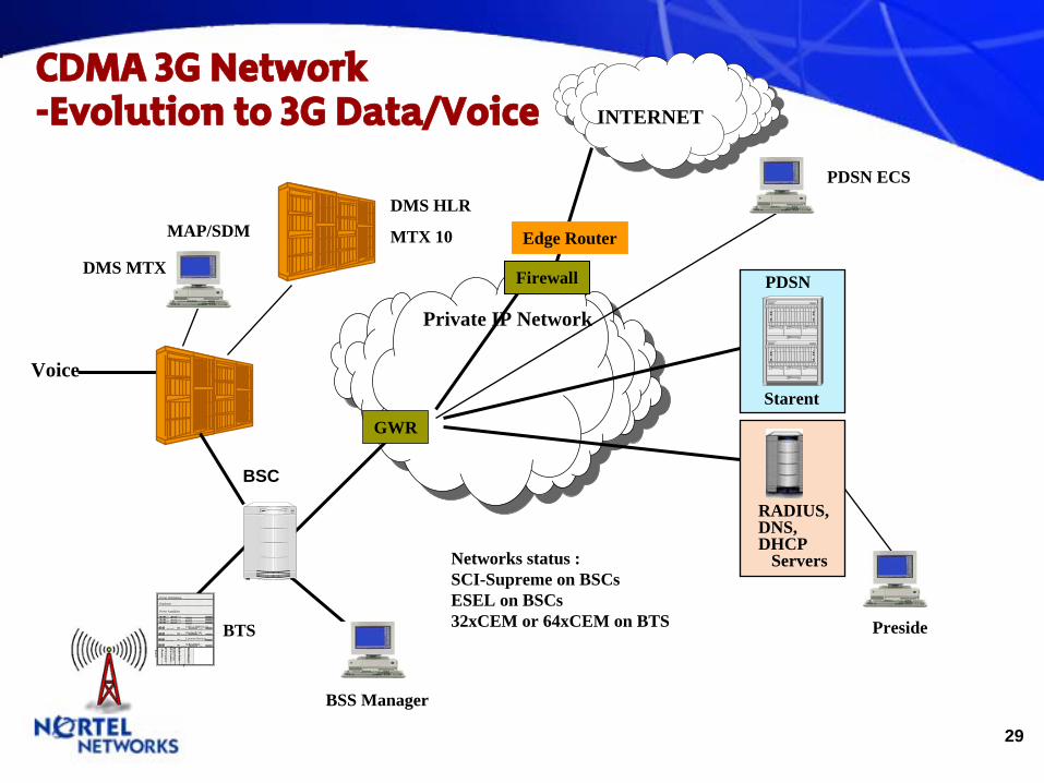
CDMA 3G Network -Evolution to 3G Data/Voice
Starent
RADIUS,DNS,DHCP
Servers
PDSNDMS MTX
Master O
scillatorSite M
anager
Main / Diversity Main / Diversity
Main / Diversity Main / DiversityMain / Diversity Main / Diversity
Main / Diversity Main / Diversity
Main / Diversity Main / DiversityMain / Diversity Main / Diversity
Spectrum In Net
work Tx
out
Router
Router
BT
S Control
BT
S Control
Radio Ports
Radio Ports
Power Distribution
WBDWBDWBDUWC-136HS (E-3)
Duplexers
Power Amplifiers
Spectrum In Net
work Tx
outIS-136 (T-24)
Spectrum In Net
work Tx
outWB-CDMA
WCDMASpectrum In Net
workLocation Services
BTS
BSC
INTERNET
BSS Manager
MAP/SDM
Preside
Voice
Private IP Network
DMS HLR
MTX 10
GWR
Edge Router
Firewall
PDSN ECS
Networks status :SCI-Supreme on BSCsESEL on BSCs32xCEM or 64xCEM on BTS
30
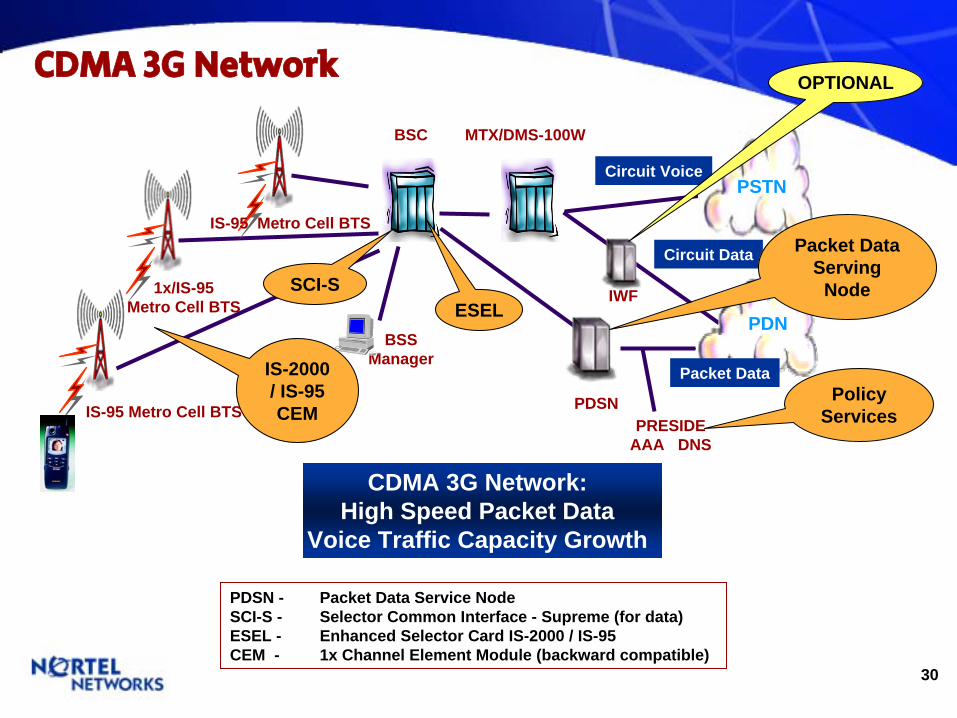
PDSN - Packet Data Service NodeSCI-S - Selector Common Interface - Supreme (for data)ESEL - Enhanced Selector Card IS-2000 / IS-95 CEM - 1x Channel Element Module (backward compatible)
1x/IS-95Metro Cell BTS
IS-95 Metro Cell BTS
BSC
PSTN
PDN
Circuit Data
Circuit Voice
IS-95 Metro Cell BTS
BSS Manager
IWF
Packet Data
PDSN
MTX/DMS-100W
OPTIONAL
Packet Data Serving
NodeSCI-SESEL
IS-2000 / IS-95 CEM
PRESIDEAAA DNS
Policy Services
CDMA 3G Network:High Speed Packet Data
Voice Traffic Capacity Growth
CDMA 3G Network

31
eBSC
eBSC/CCMC(CBRS)
MetroCell
DOMOPTera
3500(w/ DSM)
T1 OC3T1 (DTC)
(unch)
OPTera3500BTS T1
100 BaseTPassport
8600
T1
PDSN / FA DO-RNC DO-EMS
- Access AN-AAA
- Radius
100BaseT
OC3 or 100BaseTintranet
CDMA Voice/Data Network a
PDN
1xEVDO 1xRTT
Packet CoreData
Circuit CoreCell Sites
100/1000BaseT/GigE
CBRS DISCO
OC3OC3OC12
ISSHO / ATM(PP15K)
2nd
BSC
OC3OC12
To CIS(DISCO)
Packet Network
(ATM) PVG GWC
SAM21 based
DPTGWC*
CS LAN (IP)[PP8600]
XACore
ENETISM
MessageSwitch
DTC/SPM
PVG GWC
SAM21 based
DPTGWC*
CS LAN (IP)[PP8600]
XACore
ENETISM
MessageSwitch
DTC/SPM
PG-MSCPacket Core
From:DPCX
PVG15K
MTXXA-Core
T1
HA(Mobile IP)
100BaseT
OC3 or 100BaseTInternet
SERVERS(Note: Mng
Traffic)
Domestic
BPS2000
1900/800 MHz
SBSOC3
MTX
MDMNTP BSSMC-EMS
100BaseT
100BaseT
10BaseT
BPS 2000
10BaseT
SCI-S
Contivity 600
Firewall(3rd
Party)
RP InterfaceA10A12
- SCS PDSN
- Core AAA
- Radius
- SCS BSN 5000
100BaseT(w/ redundancy)
A12
WAN Router
Passport7440
ST-16(Starent)
SPM
OC3
OC3
T1Core DMS
PSTN
DTC
OPTera3500
T1
OC3or
32
CDMA BTS Portfolio
33
FOM Fiber Optic Micro Cell
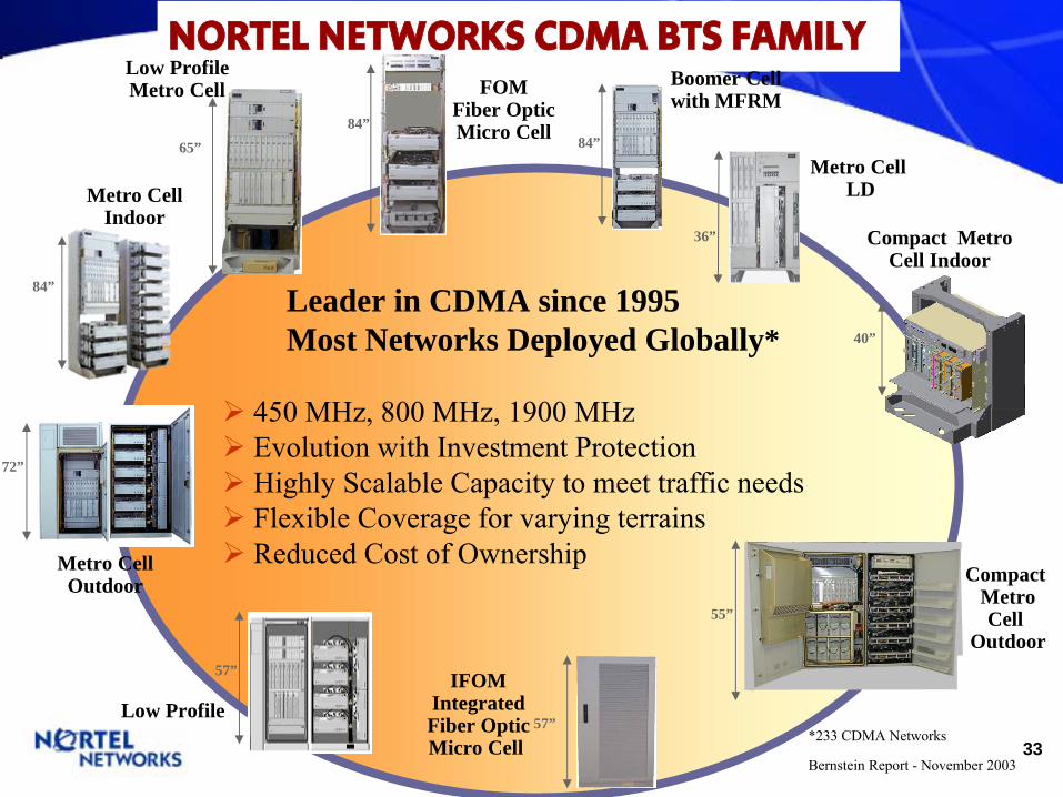
450 MHz, 800 MHz, 1900 MHz Evolution with Investment Protection Highly Scalable Capacity to meet traffic needs Flexible Coverage for varying terrains Reduced Cost of Ownership
Metro Cell LD
NORTEL NETWORKS CDMA BTS FAMILY
IFOMIntegratedFiber OpticMicro Cell
Low Profile
Low Profile Metro Cell
65”84”
Boomer Cellwith MFRM
84”
36”
Metro CellIndoor
84”
Metro CellOutdoor
72”
57”
57”
40”
Compact Metro Cell Indoor
Leader in CDMA since 1995Most Networks Deployed Globally*
*233 CDMA Networks
Bernstein Report -
November 2003
Compact Metro Cell
Outdoor55”
34
CDMA Portfolio Overview-
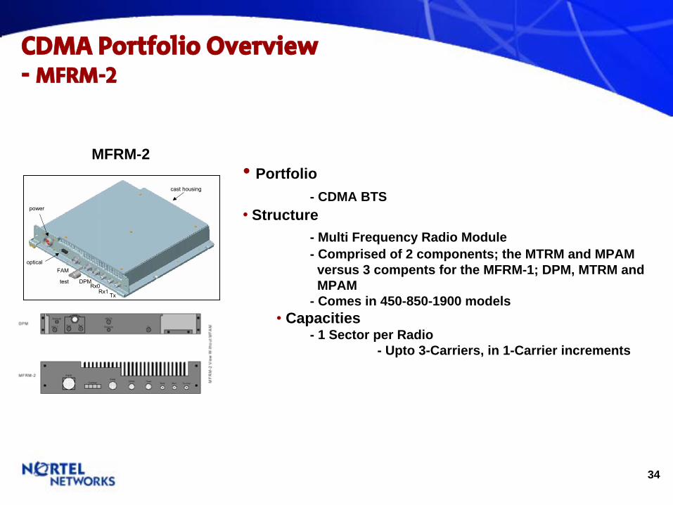
MFRM-2
•
Portfolio - CDMA BTS
•
Structure - Multi Frequency Radio Module - Comprised of 2 components; the MTRM and MPAM versus 3 compents for the MFRM-1; DPM, MTRM and MPAM
- Comes in 450-850-1900 models •
Capacities - 1 Sector per Radio
- Upto 3-Carriers, in 1-Carrier increments
MFRM-2
cast housing
power
opticalFAM
test DPMRx0
Rx1Tx
35
CDMA Portfolio Overview-
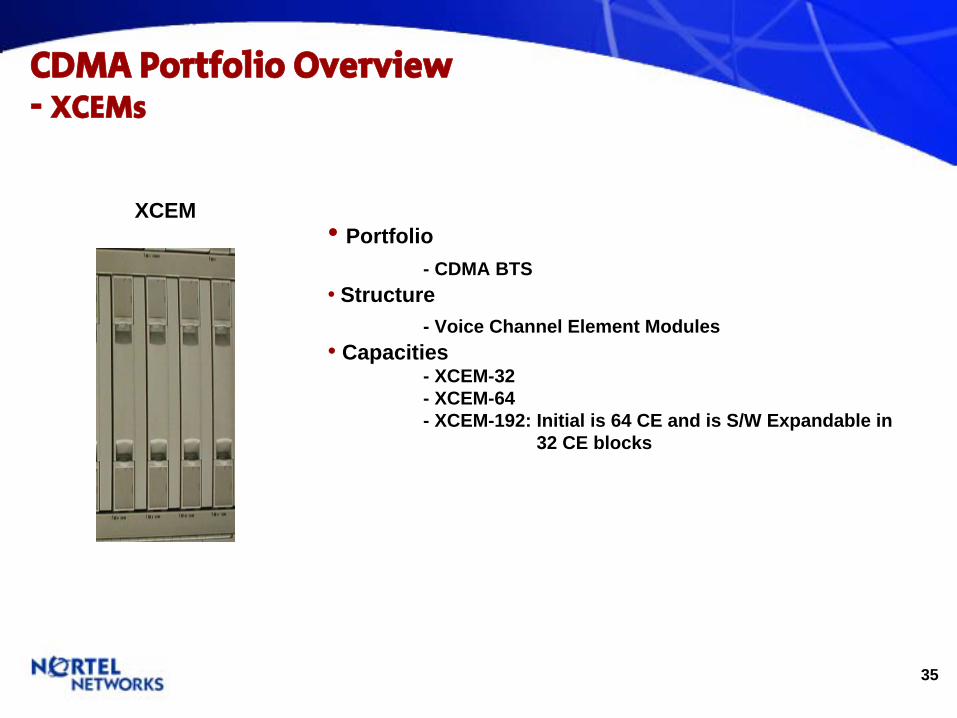
XCEMs
•
Portfolio - CDMA BTS
•
Structure - Voice Channel Element Modules
•
Capacities - XCEM-32 - XCEM-64 - XCEM-192: Initial is 64 CE and is S/W Expandable in
32 CE blocks
XCEM
36
CDMA Portfolio Overview-
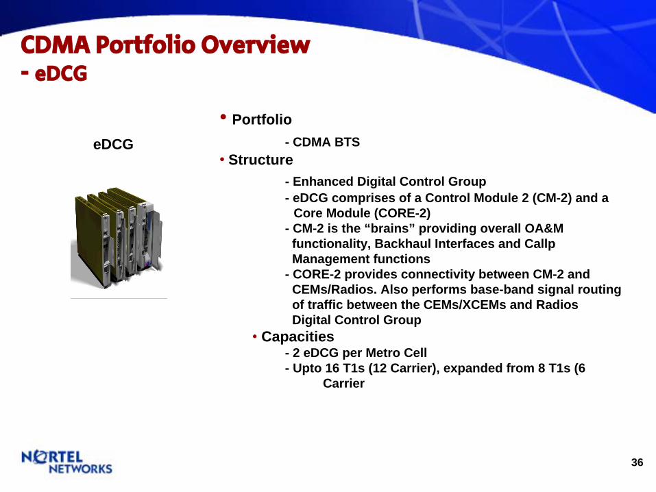
eDCG
•
Portfolio - CDMA BTS
•
Structure - Enhanced Digital Control Group - eDCG comprises of a Control Module 2 (CM-2) and a
Core Module (CORE-2)- CM-2 is the “brains” providing overall OA&M functionality, Backhaul Interfaces and Callp Management functions
- CORE-2 provides connectivity between CM-2 and CEMs/Radios. Also performs base-band signal routing of traffic between the CEMs/XCEMs and RadiosDigital Control Group
•
Capacities - 2 eDCG per Metro Cell - Upto 16 T1s (12 Carrier), expanded from 8 T1s (6
Carrier
eDCG
37
CDMA Portfolio Overview-
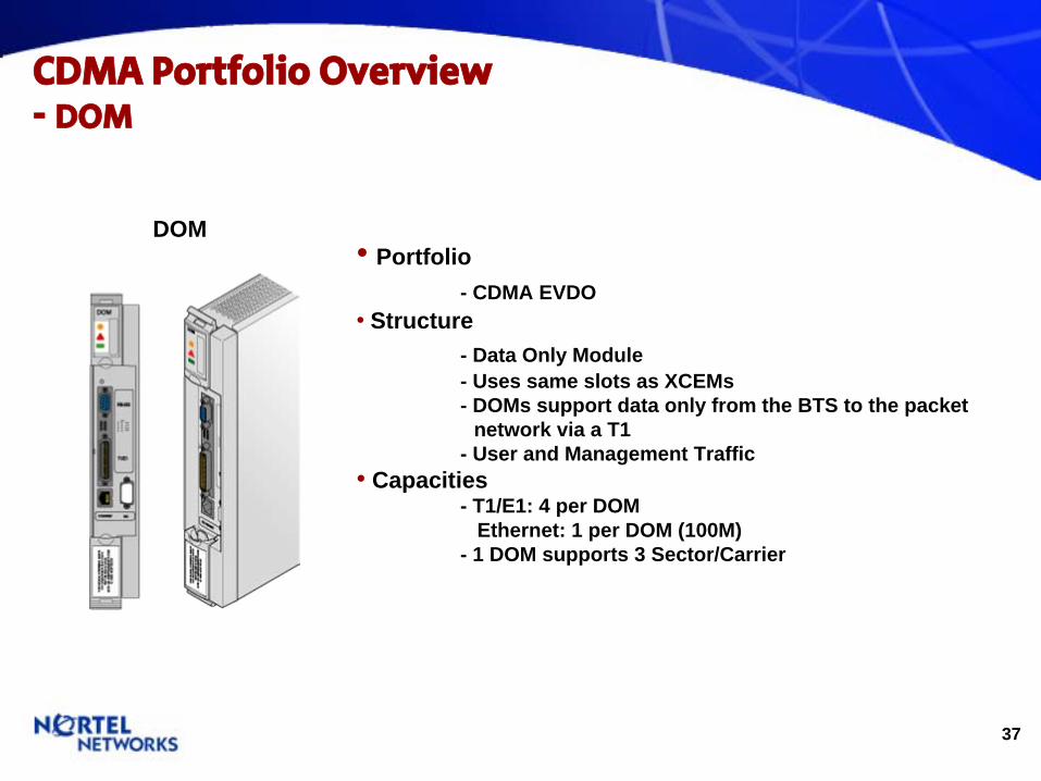
DOM
•
Portfolio - CDMA EVDO
•
Structure - Data Only Module - Uses same slots as XCEMs - DOMs support data only from the BTS to the packet
network via a T1 - User and Management Traffic
•
Capacities - T1/E1: 4 per DOM
Ethernet: 1 per DOM (100M) - 1 DOM supports 3 Sector/Carrier
DOM
38
CDMA Portfolio Overview-
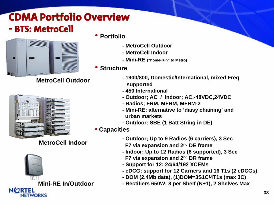
BTS: MetroCell
•
Portfolio - MetroCell Outdoor - MetroCell Indoor - Mini-RE (“home-run” to Metro)
•
Structure - 1900/800, Domestic/International, mixed Freq
supported - 450 International - Outdoor; AC / Indoor; AC,-48VDC,24VDC - Radios; FRM, MFRM, MFRM-2 - Mini-RE; alternative to ‘daisy chaining’ and
urban markets - Outdoor: SBE (1 Batt String in DE)
•
Capacities - Outdoor; Up to 9 Radios (6 carriers), 3 Sec
F7 via expansion and 2nd DE frame - Indoor; Up to 12 Radios (6 supported), 3 Sec
F7 via expansion and 2nd DR frame - Support for 12: 24/64/192 XCEMs - eDCG; support for 12 Carriers and 16 T1s (2 eDCGs) - DOM (2.4Mb data), (1)DOM=3S1C/4T1s (max 3C) - Rectifiers 650W: 8 per Shelf (N+1), 2 Shelves Max
MetroCell Outdoor
MetroCell Indoor
Mini-RE In/Outdoor

39
CDMA Portfolio Overview-
BTS: MetroCell
(cont.)
•
Portfolio - Metrocell Outdoor Skid
•
Structure - Metrocell Outdoor ONLY - Each Skid must have a DE, RE and SBE (even if back-up
not required) - All Frames mounted to the Skid at the Factory and
shipped to site ready to install. Size and weight does pose logistic issues – these must be addressed up front.
40
CDMA Portfolio Overview-
BTS: MetroCell
(cont.)
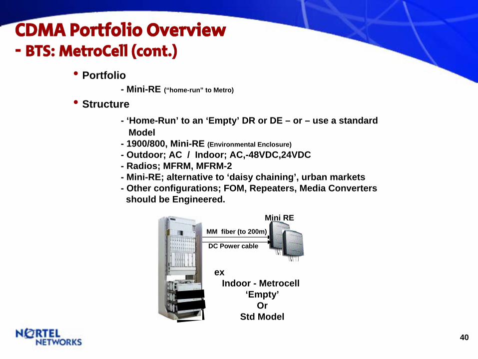
•
Portfolio - Mini-RE (“home-run” to Metro)
•
Structure - ‘Home-Run’ to an ‘Empty’ DR or DE – or – use a standard
Model - 1900/800, Mini-RE (Environmental Enclosure) - Outdoor; AC / Indoor; AC,-48VDC,24VDC - Radios; MFRM, MFRM-2 - Mini-RE; alternative to ‘daisy chaining’, urban markets - Other configurations; FOM, Repeaters, Media Converters should be Engineered.
MM fiber (to 200m)
ex Indoor - Metrocell
‘Empty’Or
Std Model
DC Power cable
Mini RE
41
CDMA Portfolio Overview-
BTS: MetroCell
(cont.)
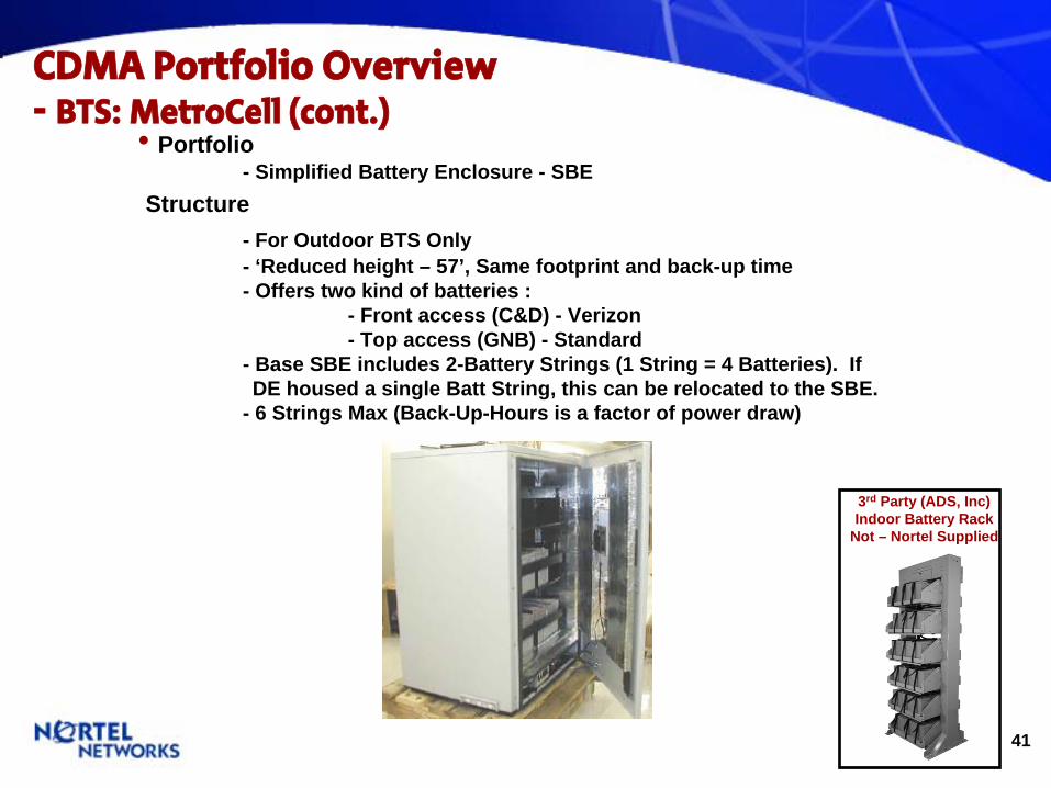
•
Portfolio - Simplified Battery Enclosure - SBE
Structure - For Outdoor BTS Only- ‘Reduced height – 57’, Same footprint and back-up time - Offers two kind of batteries :
- Front access (C&D) - Verizon- Top access (GNB) - Standard
- Base SBE includes 2-Battery Strings (1 String = 4 Batteries). If DE housed a single Batt String, this can be relocated to the SBE.
- 6 Strings Max (Back-Up-Hours is a factor of power draw)
3rd Party (ADS, Inc)Indoor Battery Rack
Not – Nortel Supplied

42
CDMA Portfolio Overview-
BTS: Compact Indoor (CMI)
•
Portfolio - Compact Metro Indoor (CMI)
•
Structure - ‘Models’ at the Frame Level only - Modular and Stackable (3’ cBTS = 7’ Metro) - Three frame options; 3’, 5’ and 7’ - 1900/800, Domestic/International, mixed Freq
supported - Indoor; -48VDC,24VDC - Compact Radio Module (RM) is MFRM-2 equivalent - Digital Components (DOMs, XCEMs) are BTS
agnostic•
Capacities - 1 Shelf: 3 RMs, 2/3 XCEMs, 1/0 DOMs - 7’ Frame: Up to 9 Radios (6 supported) can be stacked,
3 sectors per shelf. - Supports 64 and 192 XCEMs (1-3 CEMs) - Supports 1 DOM (EVDO) Carrier per Shelf - Mixed Frequency in a single frame supported
•
Model Impact - CMI Models DO NOT INCLUDE Radios (RM). RMs are
Required Selections (CR02).
Compact Indoor
=
6C3S Metro
84”
64”
6C3S CMI
43
CDMA Portfolio Overview-
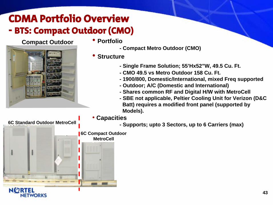
BTS: Compact Outdoor (CMO)
•
Portfolio - Compact Metro Outdoor (CMO)
•
Structure - Single Frame Solution; 55’Hx52”W, 49.5 Cu. Ft. - CMO 49.5 vs Metro Outdoor 158 Cu. Ft. - 1900/800, Domestic/International, mixed Freq supported - Outdoor; A/C (Domestic and International) - Shares common RF and Digital H/W with MetroCell - SBE not applicable, Peltier Cooling Unit for Verizon (D&C
Batt) requires a modified front panel (supported by Models).
•
Capacities - Supports; upto 3 Sectors, up to 6 Carriers (max)
Compact Outdoor
6C Compact Outdoor MetroCell
6C Standard Outdoor MetroCell
44
CDMA Portfolio Overview-
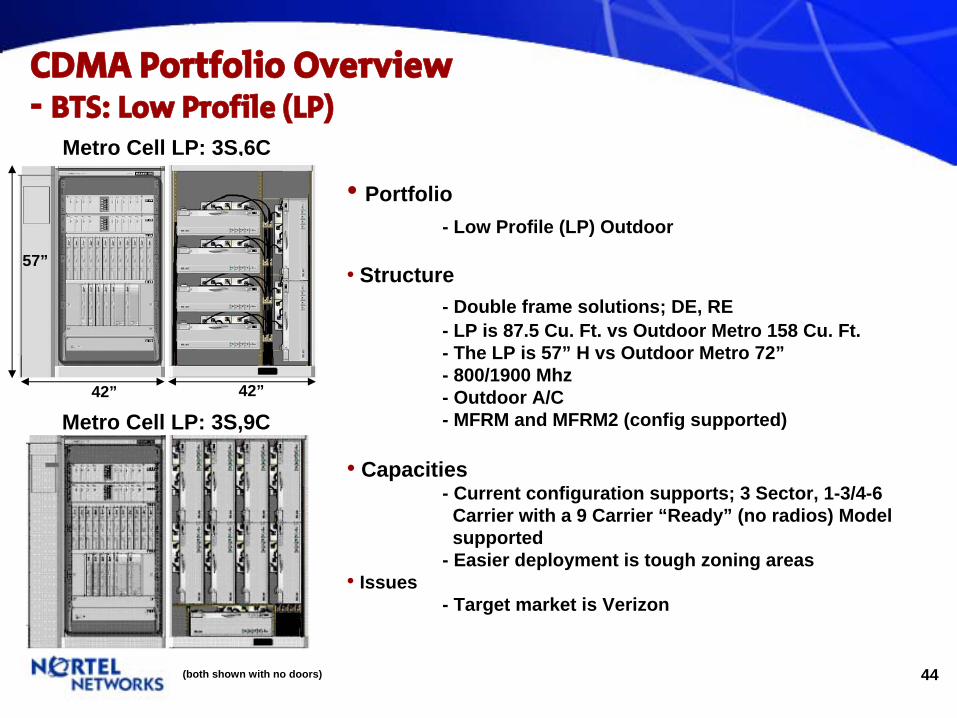
BTS: Low Profile (LP)
•
Portfolio - Low Profile (LP) Outdoor
•
Structure - Double frame solutions; DE, RE - LP is 87.5 Cu. Ft. vs Outdoor Metro 158 Cu. Ft. - The LP is 57” H vs Outdoor Metro 72” - 800/1900 Mhz - Outdoor A/C - MFRM and MFRM2 (config supported)
•
Capacities - Current configuration supports; 3 Sector, 1-3/4-6
Carrier with a 9 Carrier “Ready” (no radios) Model supported
- Easier deployment is tough zoning areas•
Issues - Target market is Verizon
Metro Cell LP: 3S,6C
42”
57”
42”
Metro Cell LP: 3S,9C
(both shown with no doors)

45
CDMA Portfolio Overview-
BTS: Lo Density (LD)
•
Portfolio - Indoor
•
Structure - Focus was China - Redesigned Indoor MetroCell Frame - 1900/800, Domestic/International - Indoor; AC, -48VDC - FRM/MFRM/MFRM2
•
Capacities - Indoor: 1S, 1-3C Configurations ONLY - MFRM/MFRM-2 support up to 3 carriers
•
Issues - Target Market is China – Asia/PAC
Lo-Density
Metro Cell LD1S,3C
42”
57”
46
Wireless eBSC
Portfolio
47
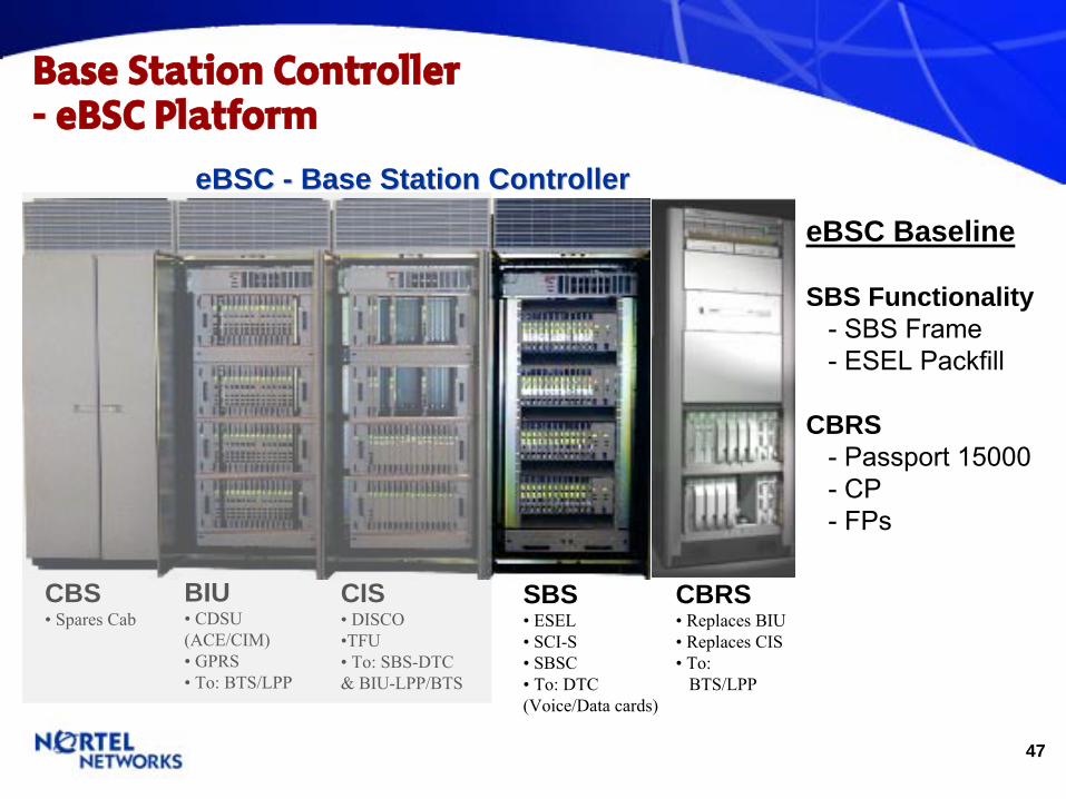
Base Station Controller-
eBSC
Platform
eBSCeBSC -- Base Station ControllerBase Station Controller
BIU•
CDSU
(ACE/CIM)• GPRS• To: BTS/LPP
CIS• DISCO•TFU•
To: SBS-DTC
& BIU-LPP/BTS
SBS• ESEL• SCI-S• SBSC•
To: DTC
(Voice/Data cards)
CBS• Spares Cab
CBRS• Replaces BIU• Replaces CIS•
To:
BTS/LPP
eBSC Baseline
SBS Functionality - SBS Frame
-
ESEL Packfill
CBRS -
Passport 15000
- CP- FPs
48
BSC Network Elements -
SBS/ESEL Configuration
Cooling Unit
SBS04
MSP
Cooling Unit
SBS03
SBS02
SBS01
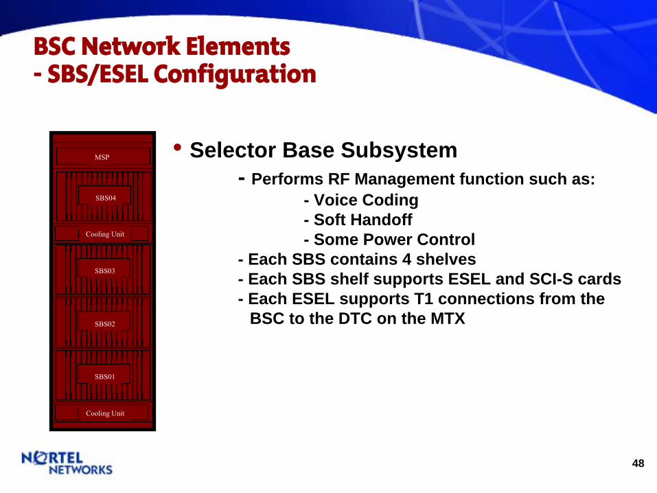
•
Selector Base Subsystem - Performs RF Management function such as:
- Voice Coding - Soft Handoff - Some Power Control
- Each SBS contains 4 shelves - Each SBS shelf supports ESEL and SCI-S cards - Each ESEL supports T1 connections from the
BSC to the DTC on the MTX
49
BSC Network Elements -
BIU / CIS Configuration
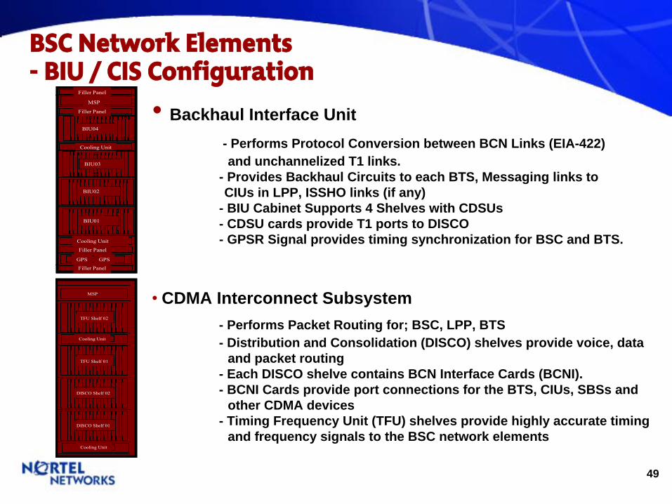
•
Backhaul Interface Unit - Performs Protocol Conversion between BCN Links (EIA-422) and unchannelized T1 links.
- Provides Backhaul Circuits to each BTS, Messaging links to CIUs in LPP, ISSHO links (if any)
- BIU Cabinet Supports 4 Shelves with CDSUs - CDSU cards provide T1 ports to DISCO - GPSR Signal provides timing synchronization for BSC and BTS.
BIU03
MSP
Filler Panel
BIU01
Cooling Unit
Cooling Unit
BIU04
Filler Panel
Filler Panel
BIU02
Filler Panel
GPS GPS
BIU03
MSP
Filler Panel
BIU01
Cooling Unit
Cooling Unit
BIU04
Filler Panel
Filler Panel
BIU02
Filler Panel
GPS GPS
Cooling Unit
TFU Shelf 02
MSP
Cooling Unit
TFU Shelf 01
DISCO Shelf 02
DISCO Shelf 01
Cooling Unit
TFU Shelf 02TFU Shelf 02
MSP
Cooling Unit
TFU Shelf 01TFU Shelf 01
DISCO Shelf 02DISCO Shelf 02
DISCO Shelf 01DISCO Shelf 01
•
CDMA Interconnect Subsystem - Performs Packet Routing for; BSC, LPP, BTS- Distribution and Consolidation (DISCO) shelves provide voice, data
and packet routing - Each DISCO shelve contains BCN Interface Cards (BCNI). - BCNI Cards provide port connections for the BTS, CIUs, SBSs and
other CDMA devices - Timing Frequency Unit (TFU) shelves provide highly accurate timing
and frequency signals to the BSC network elements

50
BSC Evolution to the eBSC -
BIU / CIS subsystems enhancements
NORTEL CDMA CIS
TFU 1
TFU 2TFU 2
DISCO 1
DISCO 2
MSP
TFU enhanced by EBSCTMEBSCTM
DISCO enhanced by 24pBCNW 24pBCNW Functional Functional ProcessorProcessor
BIU enhanced by 11pMSW 11pMSW Functional Functional ProcessorProcessor
SBS CabinetBIU Cabinet CIS Cabinet
NORTEL CDMA BIU
CDSU 2
CDSU 1
CDSU 3
CDSU 4
GPSR GPSR
MSPNORTEL CDMA SBS
SBS 1
SBS 4
SBS 3
SBS 2
MSP
BSCBSC
24pBCNW Function Processor
11pMSW Function Processor
Control Processor- Version 3 (CP3)
EBSCTM – Enhanced BSC Timing Module
0 1 2 4 6 7
8 9 1
01
11
31
41
5
EBSCTM EBSCTM
Cable Consolidation
and Multiplexer Chassis(CCMC)
CBRSCBRS
Resv, 2nd Frame connectivity
51
Base Station Controller-
eBSC
‘Building Blocks’
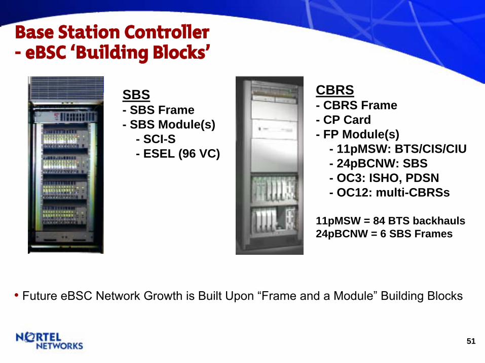
SBS - SBS Frame - SBS Module(s)
- SCI-S - ESEL (96 VC)
CBRS - CBRS Frame - CP Card - FP Module(s)
- 11pMSW: BTS/CIS/CIU - 24pBCNW: SBS - OC3: ISHO, PDSN - OC12: multi-CBRSs
11pMSW = 84 BTS backhauls 24pBCNW = 6 SBS Frames
• Future eBSC
Network Growth is Built Upon “Frame and a Module”
Building Blocks

52
CDMA CDMA eBSCeBSC
EvolutionEvolution
CIS & BIU enhanced with CBRS – NBSS 11.0
SBS(data) enhanced with CPDS – NBSS 12.1
SBS(voice) enhanced with CSVS NBSS 13.0
BSSM migrates to C-EMS – NBSS 12.1
LPP (CAU, CIU, RMU)enhanced with CSISNBSS 14.0
MTX
LPPCAU, CIU, RMU
DTC
BTS
BSC
BSCBSC SubsystemsSubsystemsBIUCIS SBS SBS
SBS–Voice/Data
CIS BIU
eBSCeBSCSubsystemSubsystem
CBRSCBRSCCDMADMA
BBackhaul & RRouting
SSubsystem
SBS–Voice/Data
BSSM
CPDSCPDSCCDMADMA PPacket
DData SSubsystem
CSVSCSVSCCDMADMA
SSelection & VVocoding
SSubsystem
CC--EMSEMSCCDMADMA EElement MManagement SSubsystem
CSISCSISCCDMADMA
SISIgnaling SSubsystem
53
eBSC
Network- eBSC Platform
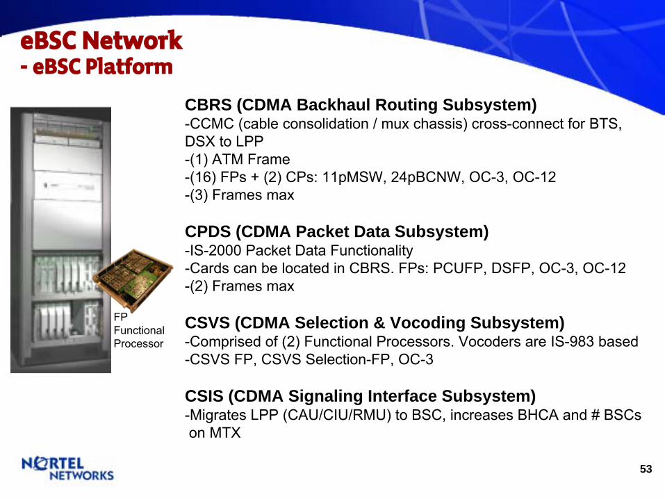
CBRS (CDMA Backhaul Routing Subsystem)-CCMC (cable consolidation / mux
chassis) cross-connect for BTS, DSX to LPP -(1) ATM Frame-(16) FPs
+ (2) CPs: 11pMSW, 24pBCNW, OC-3, OC-12-(3) Frames max
CPDS (CDMA Packet Data Subsystem)-IS-2000 Packet Data Functionality-Cards can be located in CBRS. FPs: PCUFP, DSFP, OC-3, OC-12-(2) Frames max
CSVS (CDMA Selection & Vocoding Subsystem)-Comprised of (2) Functional Processors. Vocoders
are IS-983 based-CSVS FP, CSVS Selection-FP, OC-3
CSIS (CDMA Signaling Interface Subsystem)-Migrates LPP (CAU/CIU/RMU) to BSC, increases BHCA and # BSCs
on MTX
FPFunctionalProcessor

54
CDMA Portfolio Overview- eBSC: CBRS (CDMA Backhaul Routing Subsystem)
•
Portfolio - eBSC: CBRS
•
Structure
- Built upon PP15K, with CDMA specific FPs - CBRS replaces legacy BIU and CIS functions
- BIU: replaced by 11pMSW FP - CIS (TFU,DISCO): replaced by EBSCTM,24pBCNW FP
•
Capacity - 18K (25K) Erlangs (1,008 BTSs), 3X capacity of current BSC
- 11pMWFP: 84 T1 backhual - 24p BCNWFP: 6 SBS Frames (24 SBS Shelves) - 4/16p OC3: ISSHO, PDSN, DISCO, OAM - CP: Core Processor - CCMC: 48 BCN Links
CBRS
PP15K
CCMC
PP15K
CCMC
EBSCTM
24pBCNW FP11pMSW FP
Core Proc
4 Port OC3
DS3 FP
55
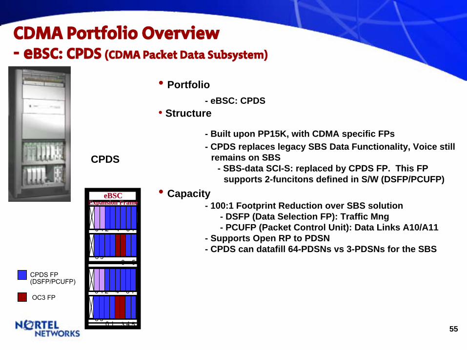
CDMA Portfolio Overview- eBSC: CPDS (CDMA Packet Data Subsystem)
•
Portfolio - eBSC: CPDS
•
Structure
- Built upon PP15K, with CDMA specific FPs - CPDS replaces legacy SBS Data Functionality, Voice still
remains on SBS - SBS-data SCI-S: replaced by CPDS FP. This FP
supports 2-funcitons defined in S/W (DSFP/PCUFP)•
Capacity
- 100:1 Footprint Reduction over SBS solution - DSFP (Data Selection FP): Traffic Mng - PCUFP (Packet Control Unit): Data Links A10/A11
- Supports Open RP to PDSN - CPDS can datafill 64-PDSNs vs 3-PDSNs for the SBS
CPDS
1
01
11
4
eBSCeBSCExpansion FrameExpansion Frame
0 1 2 4 6 7
8 9 1
31
5
0 1 2 4 6 7
8 9 1
31
5
CPDS FP(DSFP/PCUFP)
OC3 FP
56
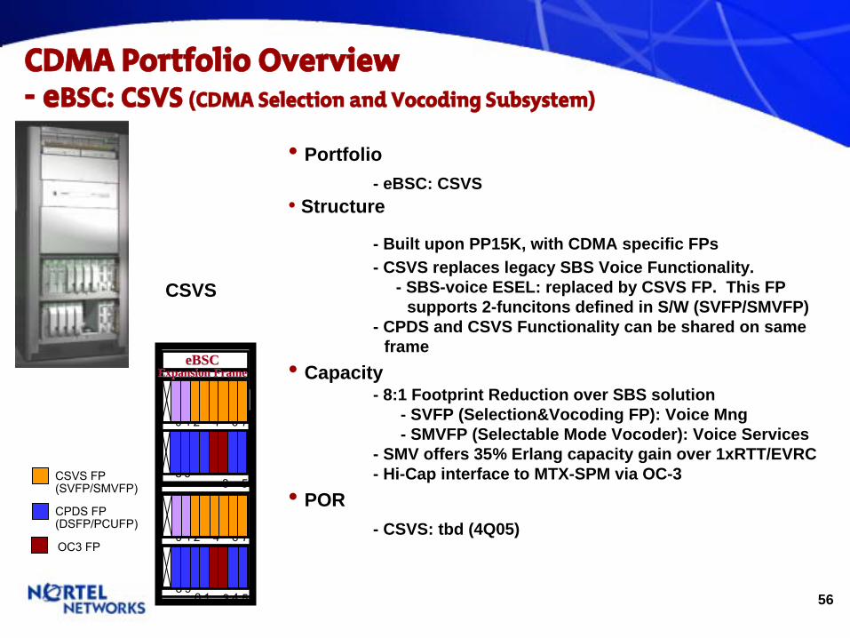
CDMA Portfolio Overview- eBSC: CSVS (CDMA Selection and Vocoding
Subsystem)
CSVS
1
01
11
4
0 1 2 4 6 7
8 9 1
31
5
0 1 2 4 6 7
8 9 1
31
5
eBSCeBSCExpansion FrameExpansion Frame
CSVS FP(SVFP/SMVFP)
OC3 FP
CPDS FP(DSFP/PCUFP)
•
Portfolio - eBSC: CSVS
•
Structure
- Built upon PP15K, with CDMA specific FPs - CSVS replaces legacy SBS Voice Functionality.
- SBS-voice ESEL: replaced by CSVS FP. This FP supports 2-funcitons defined in S/W (SVFP/SMVFP)
- CPDS and CSVS Functionality can be shared on same frame
•
Capacity - 8:1 Footprint Reduction over SBS solution
- SVFP (Selection&Vocoding FP): Voice Mng - SMVFP (Selectable Mode Vocoder): Voice Services
- SMV offers 35% Erlang capacity gain over 1xRTT/EVRC - Hi-Cap interface to MTX-SPM via OC-3
•
POR - CSVS: tbd (4Q05)
57
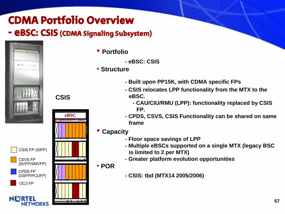
CDMA Portfolio Overview- eBSC: CSIS (CDMA Signaling Subsystem)
CSIS
CSVS FP(SVFP/SMVFP)
OC3 FP
CPDS FP(DSFP/PCUFP)
•
Portfolio - eBSC: CSIS
•
Structure
- Built upon PP15K, with CDMA specific FPs - CSIS relocates LPP functionality from the MTX to the
eBSC. - CAU/CIU/RMU (LPP): functionality replaced by CSIS
FP. - CPDS, CSVS, CSIS Functionality can be shared on same
frame•
Capacity
- Floor space savings of LPP - Multiple eBSCs supported on a single MTX (legacy BSC
is limited to 2 per MTX) - Greater platform evolution opportunities
•
POR - CSIS: tbd (MTX14 2005/2006)
1
01
11
4
0 1 2 4 6 7
8 9 1
31
5
0 1 2 4 6 7
8 9 1
31
5
eBSCeBSCExpansion FrameExpansion Frame
CSIS FP (SIFP)
58
Wireless MTX/NBSS Portfolio
59
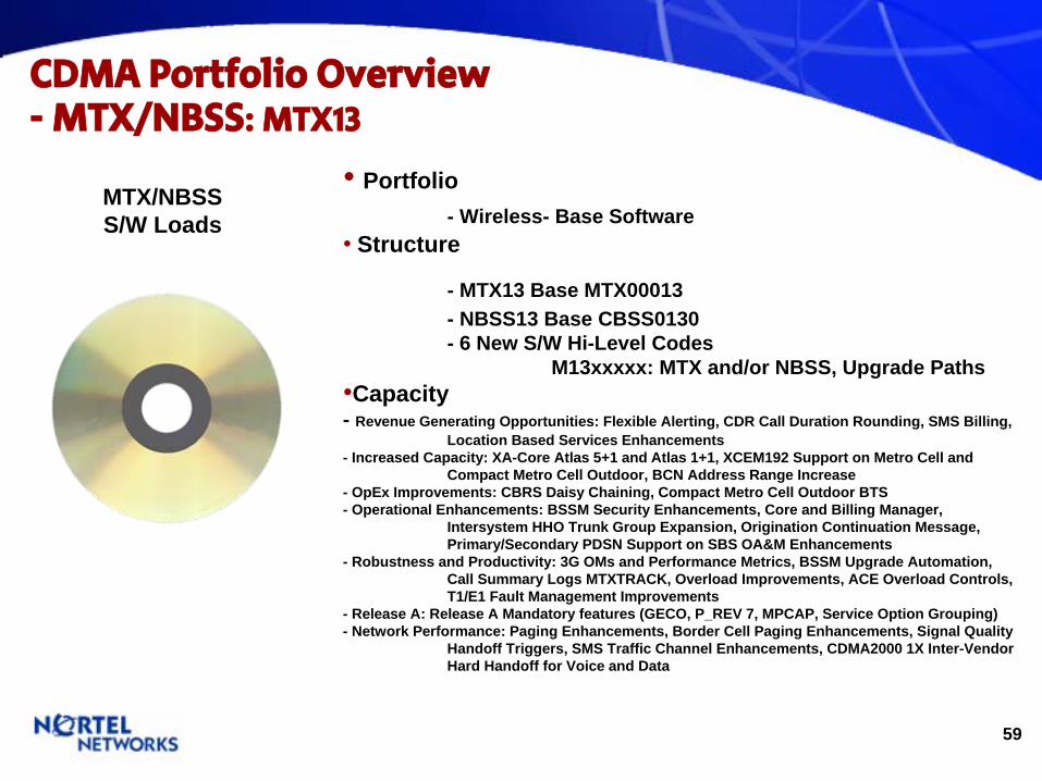
CDMA Portfolio Overview- MTX/NBSS: MTX13
•
Portfolio - Wireless- Base Software
•
Structure
- MTX13 Base MTX00013 - NBSS13 Base CBSS0130 - 6 New S/W Hi-Level Codes
M13xxxxx: MTX and/or NBSS, Upgrade Paths•Capacity - Revenue Generating Opportunities: Flexible Alerting, CDR Call Duration Rounding, SMS Billing,
Location Based Services Enhancements - Increased Capacity: XA-Core Atlas 5+1 and Atlas 1+1, XCEM192 Support on Metro Cell and
Compact Metro Cell Outdoor, BCN Address Range Increase - OpEx Improvements: CBRS Daisy Chaining, Compact Metro Cell Outdoor BTS - Operational Enhancements: BSSM Security Enhancements, Core and Billing Manager,
Intersystem HHO Trunk Group Expansion, Origination Continuation Message, Primary/Secondary PDSN Support on SBS OA&M Enhancements
- Robustness and Productivity: 3G OMs and Performance Metrics, BSSM Upgrade Automation, Call Summary Logs MTXTRACK, Overload Improvements, ACE Overload Controls, T1/E1 Fault Management Improvements
- Release A: Release A Mandatory features (GECO, P_REV 7, MPCAP, Service Option Grouping) - Network Performance: Paging Enhancements, Border Cell Paging Enhancements, Signal Quality
Handoff Triggers, SMS Traffic Channel Enhancements, CDMA2000 1X Inter-Vendor Hard Handoff for Voice and Data
MTX/NBSSS/W Loads
60
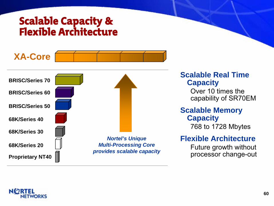
Scalable Capacity & Flexible Architecture
Scalable Real Time CapacityOver 10 times the capability of SR70EM
Scalable Memory Capacity768 to 1728 Mbytes
Flexible ArchitectureFuture growth without processor change-out
68K/Series 20
68K/Series 30
68K/Series 40
BRISC/Series 50
BRISC/Series 60
BRISC/Series 70
XA-Core
Proprietary NT40
Nortel’s UniqueMulti-Processing Core
provides scalable capacity
61
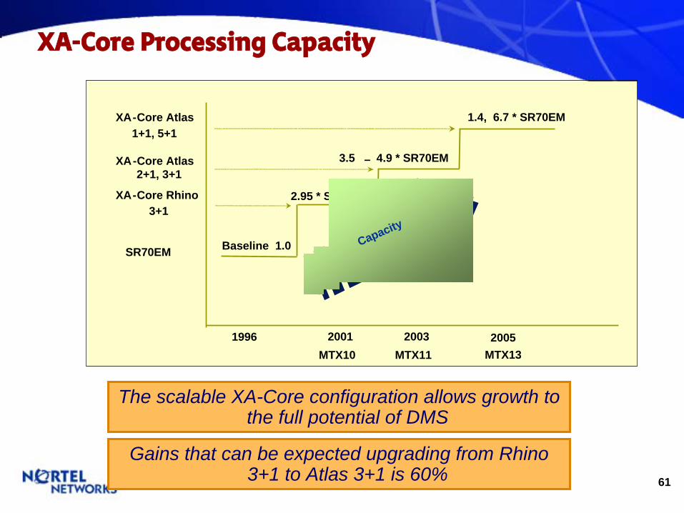
XA-Core Processing Capacity
The scalable XA-Core configuration allows growth to the full potential of DMS
Baseline 1.0
2.95 * SR70EM
1996 2001MTX10
2003MTX11
2005MTX13
XA-Core Rhino3+1
SR70EM
XA-Core Atlas2+1, 3+1
CapacityCapacity
3.5 – 4.9 * SR70EM
XA-Core Atlas1+1, 5+1
1.4, 6.7 * SR70EM
Gains that can be expected upgrading from Rhino 3+1 to Atlas 3+1 is 60%

62
Wireless MTX Portfolio

63
Mobile Telephone Exchange (MTX)ReliabilityReliability
•
Most reliable switch in service (ARMIS FCC Outage Report)
•
1/3 number of outages, 31% of mean time to restore service of nearest competitor
FlexibilityFlexibility•
Internal and external HLR/VLR choices•
Scalable from rural to dense urbanCapacityCapacity
•
128,000 lines and 512,000 subscribers•
237 K BHCA today using Brisc 60 processor•
5925 Erlangs today using Brisc 60 processorNetworking Features Networking Features
•
Feature transparency across multiple access technologies (TDMA, CDMA, AMPS)
•
Fully forward and backward compatible IS-41 networking
•
Integrated STP and Gateway MSC•
Extensive WIN Triggers
DMSDMS--MTXMTX
DMSDMS--100100WirelessWireless
(MD)(MD)
•
An Integrated Wireline / Wireless offering utilizing a single SuperNode platform
•
One Night Process (ONP) Upgrade to DMS-100/200•
Supports full suite of Wireline and Wireless Services and new integrated services
•
Supports CDMA, AMPS and TDMA•
Supports Visitor Location Register (VLR), Home Location Register (HLR), and IS-41 for roaming
•
Supports integrated Authentication Center and Circuit Switched data as of LWW0005
•
Separate billing streams for wireless and wireline
64
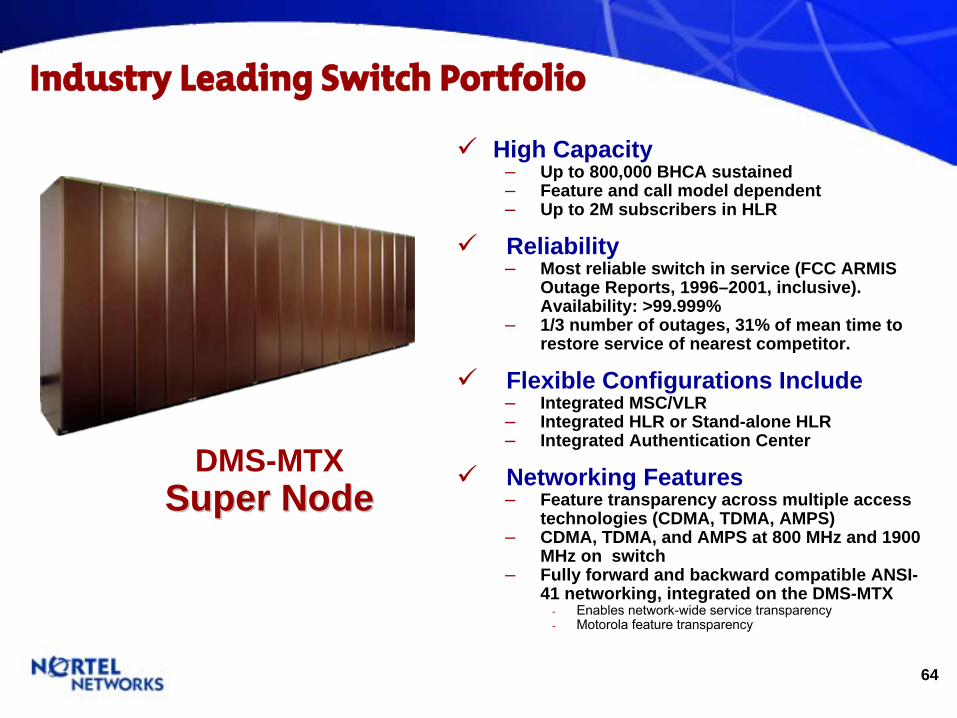
DMS-MTXSuper NodeSuper Node
Industry Leading Switch Portfolio
High Capacity–
Up to 800,000 BHCA sustained–
Feature and call model dependent–
Up to 2M subscribers in HLR
Reliability–
Most reliable switch in service (FCC ARMIS Outage Reports, 1996–2001, inclusive). Availability: >99.999%
–
1/3 number of outages, 31% of mean time to restore service of nearest competitor.
Flexible Configurations Include–
Integrated MSC/VLR–
Integrated HLR or Stand-alone HLR–
Integrated Authentication Center
Networking Features –
Feature transparency across multiple access technologies (CDMA, TDMA, AMPS)
–
CDMA, TDMA, and AMPS at 800 MHz and 1900 MHz on switch
–
Fully forward and backward compatible ANSI- 41 networking, integrated on the DMS-MTX
-
Enables network-wide service transparency-
Motorola feature transparency
65
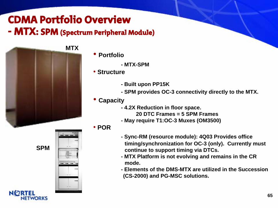
CDMA Portfolio Overview- MTX: SPM (Spectrum Peripheral Module)
•
Portfolio - MTX-SPM
•
Structure
- Built upon PP15K - SPM provides OC-3 connectivity directly to the MTX.
•
Capacity - 4.2X Reduction in floor space.
20 DTC Frames = 5 SPM Frames - May require T1:OC-3 Muxes (OM3500)
•
POR - Sync-RM (resource module): 4Q03 Provides office
timing/synchronization for OC-3 (only). Currently must continue to support timing via DTCs.
- MTX Platform is not evolving and remains in the CR mode.
- Elements of the DMS-MTX are utilized in the Succession (CS-2000) and PG-MSC solutions.
MTX
SPM
66
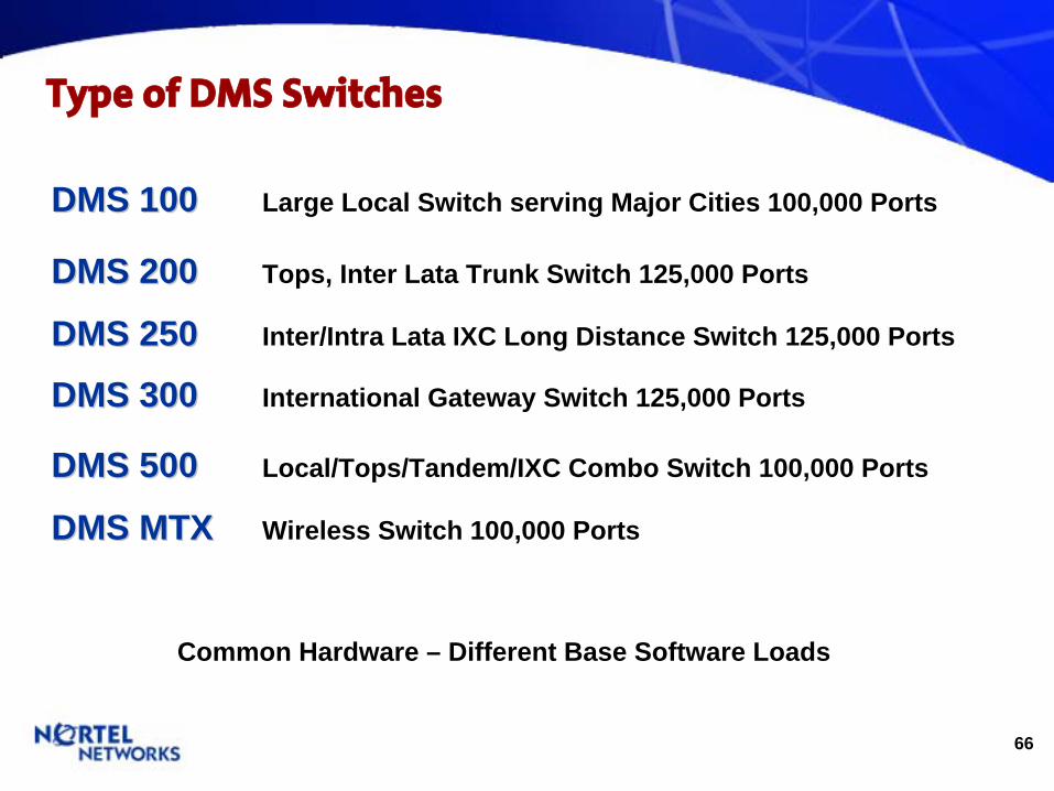
Type of DMS Switches
DMS 100DMS 100 Large Local Switch serving Major Cities 100,000 Ports
DMS 200DMS 200 Tops, Inter Lata Trunk Switch 125,000 Ports
DMS 250DMS 250 Inter/Intra Lata IXC Long Distance Switch 125,000 Ports
DMS 300DMS 300 International Gateway Switch 125,000 Ports
DMS 500DMS 500 Local/Tops/Tandem/IXC Combo Switch 100,000 Ports
DMS MTXDMS MTX Wireless Switch 100,000 Ports
Common Hardware – Different Base Software Loads
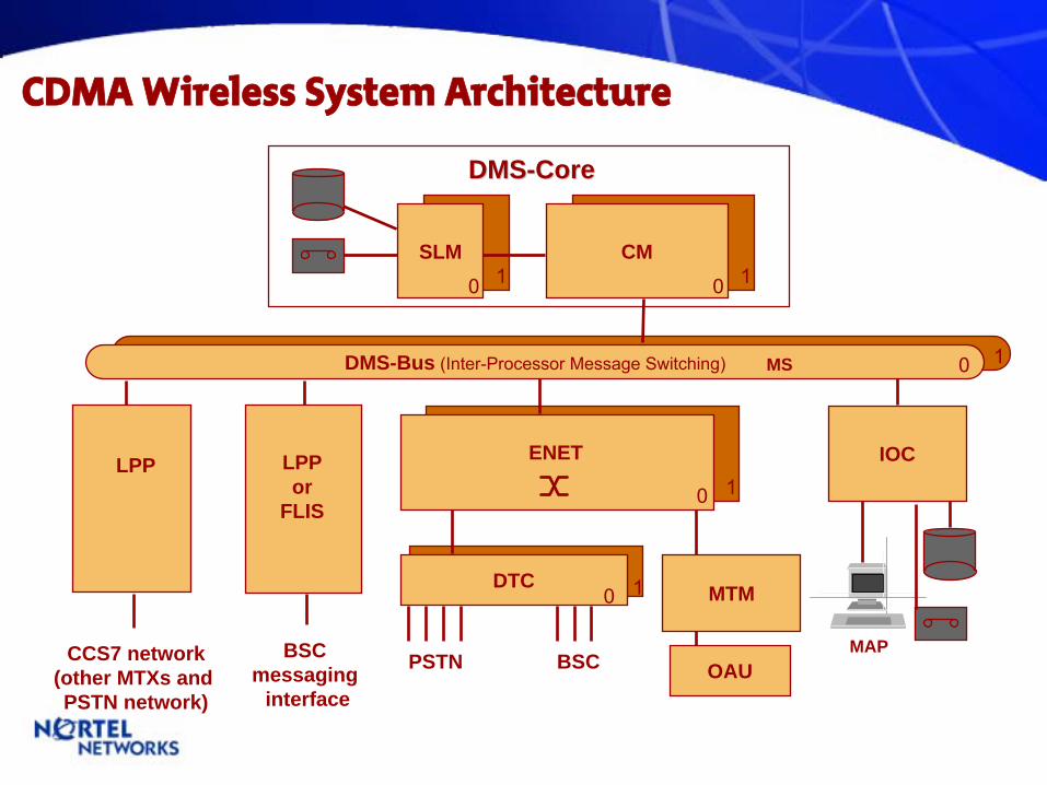
DMS-Bus (Inter-Processor Message Switching) 0 1
IOC
0
ENETLPPor
FLIS
DTC MTM
OAU
MS
PSTN BSCCCS7 network(other MTXs andPSTN network)
MAP
1
BSC messaging
interface
LPP
CMSLM00 11
DMSDMS--CoreCore
0 1
CDMA Wireless System Architecture
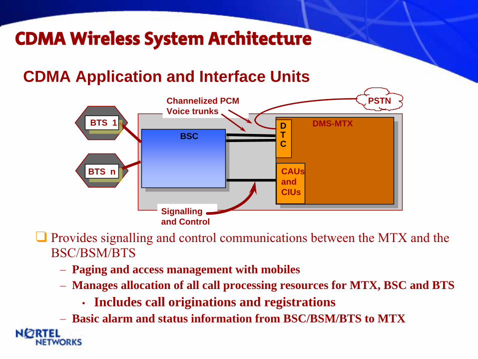
CDMA Application and Interface Units
Provides signalling
and control communications between the MTX and the BSC/BSM/BTS
–
Paging and access management with mobiles–
Manages allocation of all call processing resources for MTX, BSC and BTS •
Includes call originations and registrations–
Basic alarm and status information from BSC/BSM/BTS to MTX
DMS-MTXDTC
PSTN
BTS n
BTS 1BSC
CAUsandCIUs
Channelized PCMVoice trunks
Signallingand Control
CDMA Wireless System Architecture
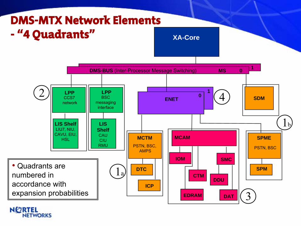
DMS-MTX Network Elements-
“4 Quadrants” XA-Core
1DMS-BUS (Inter-Processor Message Switching) MS 0
ENET1
0LPPCCS7network
LPPBSC
messaginginterface
LIS ShelfLIU7, NIU,
CAVU, EIU,HSL
LIS ShelfCAUCIURMU
MCTMPSTN, BSC,
AMPS
DTC
MCAM
CTM
IOM
EDRAM DAT
SMC
DDU
SDM
SPME
PSTN, BSC
SPM
ICP
1a
2 4
3
1b
•
Quadrants are numbered in accordance with expansion probabilities
70
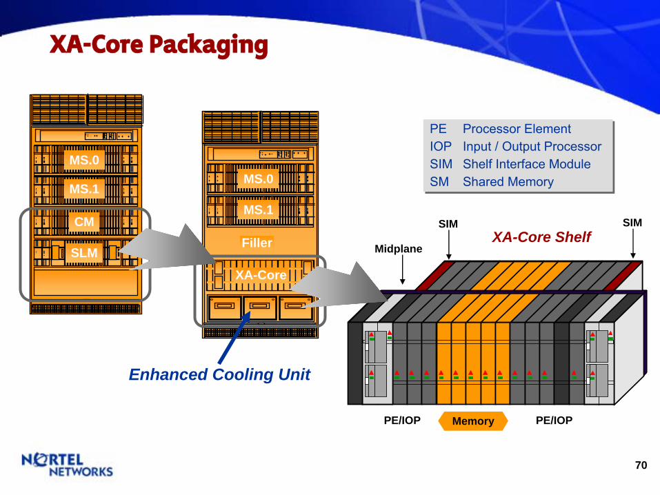
XA-Core Packaging
XA-Core
Filler
MS.0
MS.1
SLM
CM
PE
Processor ElementIOP
Input / Output ProcessorSIM
Shelf Interface ModuleSM
Shared Memory
PE
Processor ElementIOP
Input / Output ProcessorSIM
Shelf Interface ModuleSM
Shared Memory
Enhanced Cooling Unit
SIM SIM
PE/IOP Memory PE/IOP
XA-Core ShelfMidplane
MS.0
MS.1
71
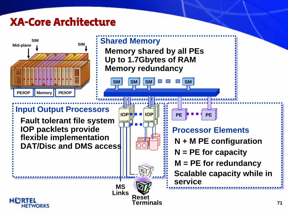
XA-Core Architecture
Shared Memory
Input Output Processors
Processor ElementsN + M PE configuration N = PE for capacityM = PE for redundancy
PE PE
SM SMSM SM
MS Links Reset
Terminals
IOP IOP
Memory shared by all PEsUp to 1.7Gbytes of RAMMemory redundancy
Fault tolerant file systemIOP packlets provide flexible implementationDAT/Disc and DMS access
Scalable capacity while in service
SIMSIMMid-plane
PE/IOP Memory PE/IOP

72
MTX - Switching Platform
•
Enhanced NETwork -
Bearer Path, 128K channels
-
non-Blocking
-
Matrixed
Timeswitch
LMS.0&1FLIS 0FLIS 2FLIS 3
Key DMS-MTX Components
MS 00MS 01
XA CoreXA Core
ENET 00ENET 01ENET 10ENET 11
CORE MCAM
72”
42”
28.5”
28”
ENET FLPP MCTMV SPME
•
Core - Message Switch (MS)
-
Fully redundant, dual plane architecture
-
Core (XA-Core)
-
Processor Elements (PE) reside
-
Share Memory modules (SM) reside
•
Fiberized Link Peripheral Processor -
Local Message Switch
-
MTX-BSC / MTX-PSTN Message Link
-
‘Networking’
FLPP: LIU7, EIU, NIU, CAVU -
‘CDMA’
LPP: CIU, CAU, RMU
ISM
ISM
ISM (opt)
PDP
•
Meridian Cabinet Aux Module -
Supply service circuits and power distribution to the MCTMV frame
-
Integrated Service Modules shelves: IOM, EDRAMs, CTM,
EDTU
DTC
DTC
•
Meridian Cabinet Trunk Module -
Digital Trunking
interface to PSTN, BSC, other MTXs
-
DTC, each provides up to 20 T1s•
Spectrum Peripheral Module Enclosure -
SPM provides an OC-3 (1 OC-3 = 84 T1s)
-
Note: Different H/W than MCTMV
•
Base MTX line up consists of multiple Frames – defined by Traffic and Networking requirements
•
Key Growth Elements are: - DTCs and/or SPMs - LPP: CDMA (CAUs, CIUs)
•
Expansion ‘Building Blocks’; - Frames - Packfill (grouped cards) - Cards
•
Power Frames - PDC: CORE, ENET, LPP, SPME
73
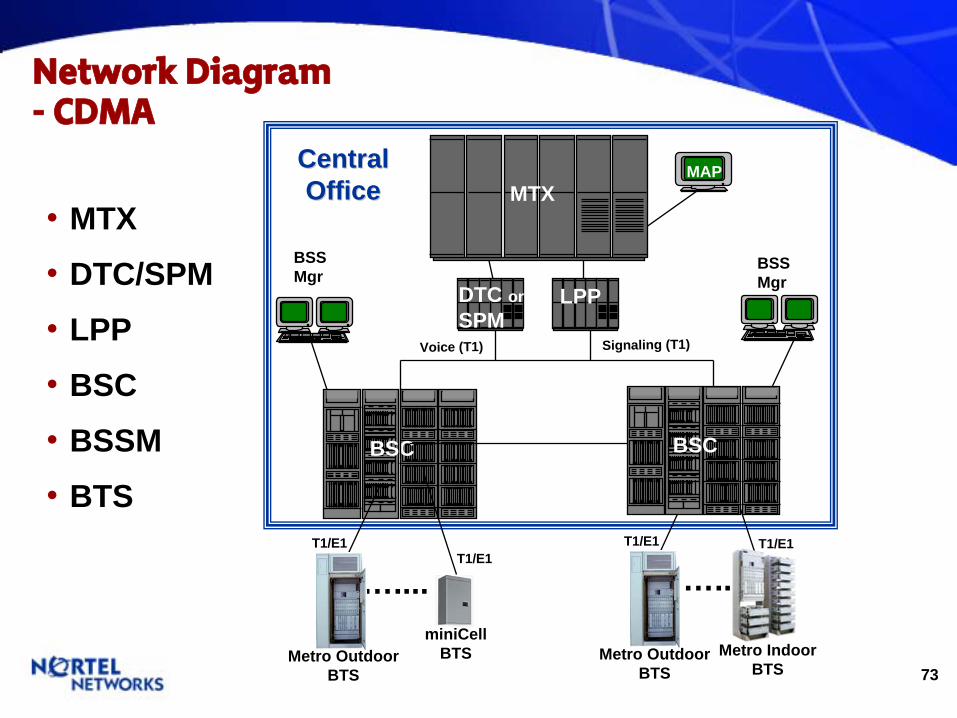
•
MTX
•
DTC/SPM
•
LPP
•
BSC
•
BSSM
•
BTSBSC
…....T1/E1
BSS Mgr
Voice (T1) Signaling (T1)
…..T1/E1
T1/E1 T1/E1
MTX
DTC or SPM
LPP
BSC
BSC
BTS BTS
MAP
BSS Mgr
Metro OutdoorBTS
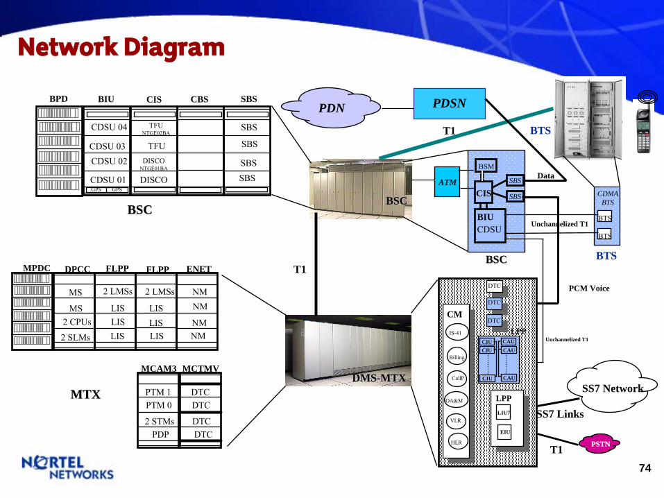
Network Diagram -
CDMA
CentralCentralOfficeOffice
miniCellBTS Metro Outdoor
BTSMetro Indoor
BTS
74
Network Diagram
BTS
DMSDMS--MTXMTX
BSCBSC
SS7 Links
T1
SS7 Network
T1
CIS SBSBPD BIU CBS
SBS
SBS
SBSSBS
TFUNTGE02BA
TFUDISCO
NTGE01BA
DISCO
CDSU 04
CDSU 03CDSU 02
CDSU 01GPS GPS
BSCBSC
PCM Voice
ATM
BTS
BTS
CDMABTS
BSM
CIS
CDSUBIU
SBS
SBS
PSTNPSTN
Unchannelized T1
Unchannelized T1
BTSBSCBSC
MTXMTX
FLPPMPDC DPCC FLPP ENET
NMNM
NMNM
2 LMSs
LISLISLIS
MS
MS2 CPUs
2 SLMs
2 LMSs
LISLISLIS
MCAM3
PTM 1PTM 0
2 STMsPDP
MCTMV
DTCDTC
DTCDTC
T1
CM
IS-41
Billing
CallP
OA&M
VLR
HLR
LPPLIU7
DTC
LPPDTC
DTC
CIUCIU
CIU
CAU
CAU
CAU
EIU
PDSNPDN
Data

75
MTX - Switch ‘Building Blocks’
MS 00MS 01
XA CoreXA Core
Core
ENET 00ENET 01ENET 10ENET 11
ENET
LMS.0&1FLIS 0FLIS 2FLIS 3
LPP
ISM
ISM
ISM (opt)
PDP
MCAM
DTC
DTC
MCTM SPME
SPM
SPM
•
Module(s) - MS Ports - PEs
Note: Based on typical expansion of a ‘Greenfield’
switch
• Card(s)• Packfill• Frame
•
Module(s) - IOM - EDRAM - CTM - EDTU
• Frame
• Frame•
Card(s) - CAU - CIU - RMU - EIU - LIU - CAVU - NIU
• Frame•
Packfill - DTC
-> T1 -> CAP -> CTD
• Frame•
Packfill - SPM
-> OC3
Initial MTX - No Frame Exp-
MS tied to ENET/LPP
-
PE tied to traffic and features
Initial MTX - Tied to
DTC/SPMs
Initial MTX -
Tied to Features-
Tied to Power
Initial MTX -
(1) Tied to PSTN Trunking
-
(2) Tied to BTS count / BSC capacity
Growth - Tied to traffic- T1/E1
Growth -
Tied to traffic-
Optical; OC3/STM1
76
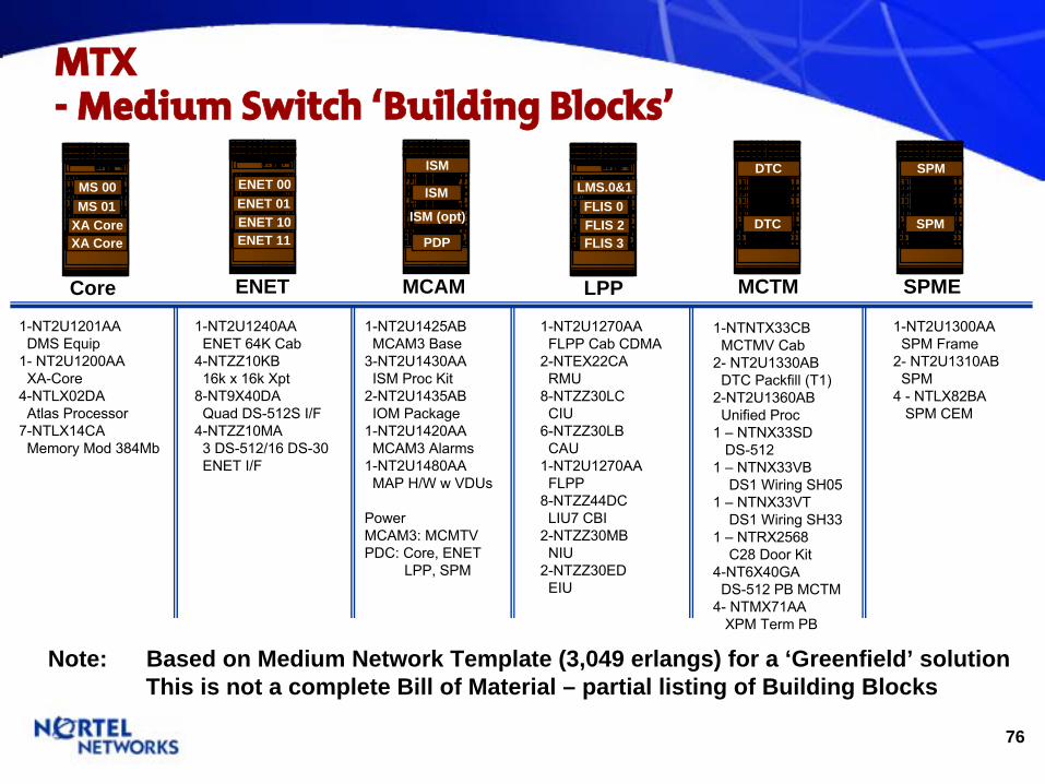
MTX -
Medium Switch ‘Building Blocks’
MS 00MS 01
XA CoreXA Core
Core
ENET 00ENET 01ENET 10ENET 11
ENET
LMS.0&1FLIS 0FLIS 2FLIS 3
LPP
ISM
ISM
ISM (opt)
PDP
MCAM
DTC
DTC
MCTM SPME
SPM
SPM
1-NT2U1201AADMS Equip
1-
NT2U1200AA
XA-Core4-NTLX02DA
Atlas Processor
7-NTLX14CA
Memory Mod 384Mb
1-NT2U1240AAENET 64K Cab
4-NTZZ10KB
16k x 16k Xpt8-NT9X40DA
Quad DS-512S I/F4-NTZZ10MA
3 DS-512/16 DS-30
ENET I/F
1-NT2U1425ABMCAM3 Base
3-NT2U1430AA
ISM Proc Kit2-NT2U1435ABIOM Package
1-NT2U1420AA
MCAM3 Alarms
1-NT2U1480AA
MAP H/W w VDUs
Power
MCAM3: MCMTVPDC: Core, ENET
LPP, SPM
1-NT2U1270AAFLPP Cab CDMA
2-NTEX22CARMU
8-NTZZ30LC
CIU6-NTZZ30LBCAU
1-NT2U1270AA
FLPP
8-NTZZ44DC
LIU7 CBI2-NTZZ30MB
NIU2-NTZZ30EDEIU
1-NT2U1300AASPM Frame
2-
NT2U1310AB
SPM
4 -
NTLX82BA
SPM CEM
1-NTNTX33CB
MCTMV Cab
2-
NT2U1330AB
DTC Packfill
(T1)
2-NT2U1360AB
Unified Proc
1 –
NTNX33SD
DS-512
1 –
NTNX33VB
DS1 Wiring SH05
1 –
NTNX33VT
DS1 Wiring SH33
1 –
NTRX2568
C28 Door Kit4-NT6X40GA
DS-512 PB MCTM4-
NTMX71AA
XPM Term PB
Note: Based on Medium Network Template (3,049 erlangs) for a ‘Greenfield’ solution This is not a complete Bill of Material – partial listing of Building Blocks
77
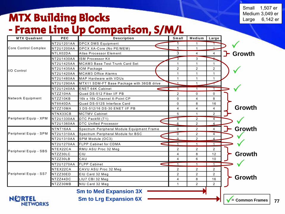
M TX Q uadrant PEC Description Sm all M edium LargeNT2U1201AA DPCX DM S Equipm ent 1 1 1NT2U1200AA DPCX XA-Core (No PE/M EM ) 1 1 1NTLX02DA Atlas P rocessor E lem ent 3 4 4NT2U1430AA ISM Processor K it 3 3 3NT2U1425AA M CAM 3 Base Test Trunk Card Set 1 1 1NT2U1435AA IO M Package 2 2 2NT2U1420AA M CAM 3 O ffice A larm s 1 1 1NT2U1480AA M AP Hardware with VDUs 1 1 1NT2U1290AA M TX11 SDM -FT Base Package w ith 36G B drive 1 1 1NT2U1240AA ENET 64K Cabinet 1 1 1NTZZ10HA Q uad DS-512 F iber I/F PB 2 0 0NTZZ10KB 16k x 16k Channel X-Point CP 0 4 8NT9X40DA Q uad DS-512S Interface Card 0 8 16NTZZ10M A 3 DS-512/16 DS-30 ENET I/F PB 4 4 4NTNX33CB M CTM V Cabinet 5 1 2NT2U1330AA DTC Packfill (T1) 6 2 4NT2U1360AA DTC Unified P rocessor 6 2 4NTNT16AA Spectrum Peripheral M odule Equipm ent Fram e 0 2 4NT2U1310AA Spectrum Peripheral M odule for BSC 0 2 4NT2U1310AA SPM M odule (O C3) 0 2 4NT2U1270AA FLPP Cabinet for CDM A 1 1 1NTEX22CA RM U ASU Proc 32 M eg 2 2 2NTZZ30LC CIU 4 8 12NTZZ30LB CAU 4 6 10NT2U1270AA FLPP Cabinet 1 1 1NTEX22CA CAVU ASU Proc 32 M eg 2 2 2NTZZ30ED EIU Card 32 M eg 2 2 2NTZZ44DC LIU7 CBI 32 M eg 4 8 16NTZZ30M B NIU Card 32 M eg 1 2 2
Peripheral Equip - SPM
Peripheral Equip - SS7
Peripheral Equip - SBS
Core Control Com plex
I/O Control
Network Equipm ent
Peripheral Equip - XPM
MTX Building Blocks-
Frame Line Up Comparison, S/M/L
Sm to Med Expansion 3XSm to Lrg Expansion 6X
= Common Frames
Growth
Growth
Growth
Growth
Small 1,507 erMedium 3,049 erLarge 6,142 er
Growth

78
MTX -
‘Building Block’
Expansion
•
A typical “small”
MTX can be significantly expanded. •
‘Building Blocks’
accommodate MTX network expansion. •
The typical ‘Building Blocks’
represents the lowest common denominator –
ensuring flexibility.•
‘Building Blocks’
are based on:
-
Frames
-
Packfills
-
Modules
-
Cards
6,142
3,049
1,507
Erla
ngs
Medium
Small
Large
6,142
3,049
1,507
Erla
ngs
Medium
Small
Large
Sm to Med GrowthSm to Lrg Growth
MTX Expansion
Building Blocks
Increments
79
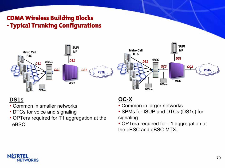
CDMA Wireless Building Blocks
-
Typical Trunking
Configurations
eBSC
Metro CellBTS
MSC
ISUP/MF
PSTN
DS1DS1
DS1DS1DS1DS1
DS1DS1
OPTera
DS1s • Common in smaller networks• DTCs
for voice and signaling•
OPTera
required for T1 aggregation at the eBSC
OC-X • Common in larger networks•
SPMs
for ISUP and DTCs
(DS1s) for signaling•
OPTera
required for T1 aggregation at the eBSC
and eBSC-MTX.
eBSC
Metro CellBTS
MSC
ISUP/MF
PSTN
DS1DS1
OC3OC3OC3OC3DS1DS1
OPTera
OPTera
eBSC
Metro CellBTS
MSC
ISUP/MF
PSTN
DS1DS1
OC3OC3OC3OC3DS1DS1
OPTera
OPTera
80
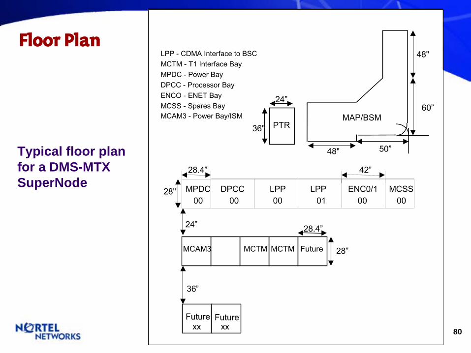
Floor Plan
MAP/BSM PTR 36"
MPDC - Power BayDPCC - Processor Bay
LPP - CDMA Interface to BSC
ENCO - ENET BayMCSS - Spares BayMCAM3 - Power Bay/ISM
MCTM - T1 Interface Bay
DPCC 28" 00
28.4”
LPP 00
Future Future
LPP 01
ENC0/1 00
MPDC 00
MCSS 00
xx xx
MCAM3 MCTM MCTM Future
28.4” 42”
24”
48"
48"
60”
50”
24 ”
36 ”
28”
Typical floor plan for a DMS-MTX SuperNode
81
Wireless Packet Portfolio
82
Wireless Packet Portfolio -
P-MSC (Gateway)
- P-MSC (Serving)
83
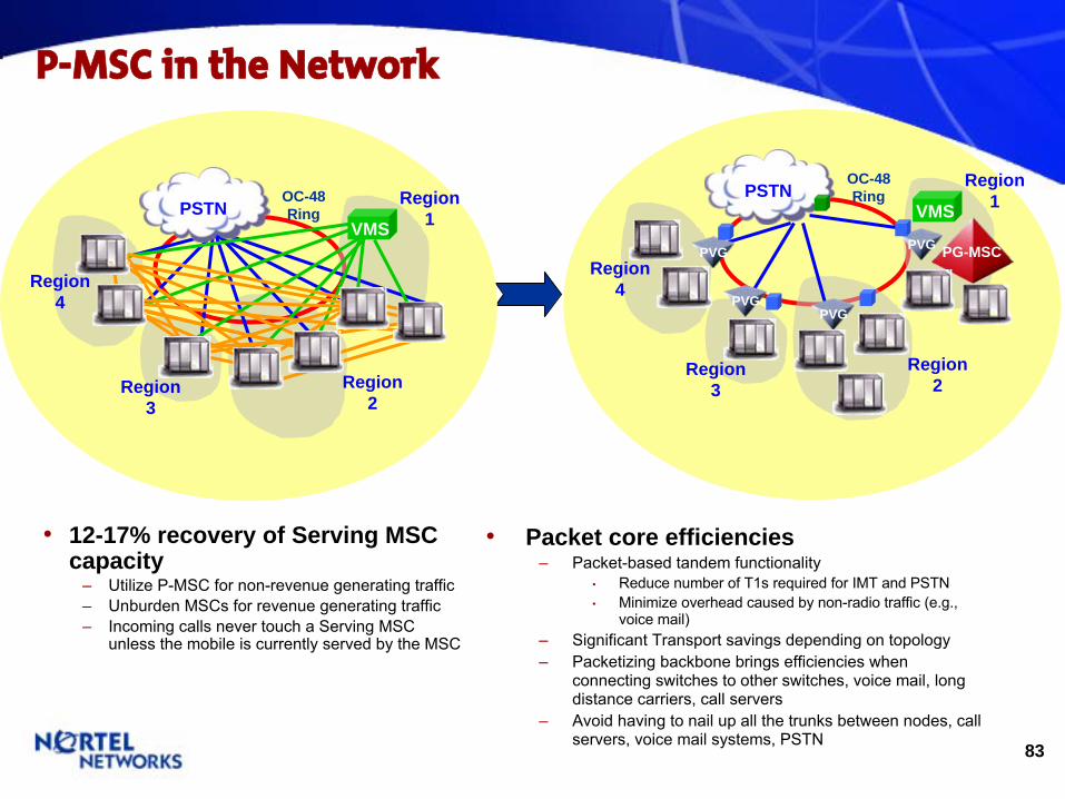
P-MSC in the Network
•
12-17% recovery of Serving MSC capacity
–
Utilize P-MSC for non-revenue generating traffic–
Unburden MSCs for revenue generating traffic –
Incoming calls never touch a Serving MSC unless the mobile is currently served by the MSC
•
Packet core efficiencies–
Packet-based tandem functionality•
Reduce number of T1s required for IMT and PSTN•
Minimize overhead caused by non-radio traffic (e.g., voice mail)
–
Significant Transport savings depending on topology–
Packetizing backbone brings efficiencies when connecting switches to other switches, voice mail, long distance carriers, call servers
–
Avoid having to nail up all the trunks between nodes, call servers, voice mail systems, PSTN
PSTNVMS
Region1
PVG
PVGPVG
PVG
Region2
Region3
OC-48Ring
PG-MSCRegion
4
Region1
Region2
Region3
OC-48Ring
Region4
PSTNVMS
84
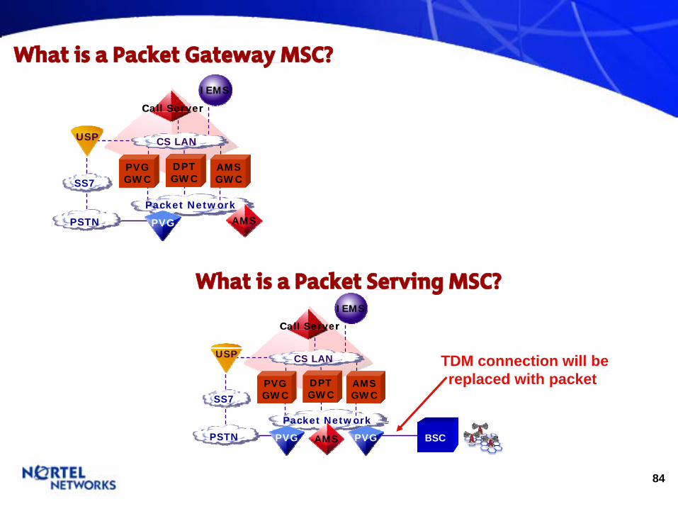
What is a Packet Gateway MSC?
SS7
IEMS
Packet Network
Call Server
PSTN
ISM
USP
AMS
AMS GWC
CS LAN
PVG GWC
DPT GWC
PVG
SS7SS7
IEMS
Packet NetworkPacket Network
Call Server
PSTNPSTN
ISM
USPUSP
AMSAMS
AMS GWCAMS GWC
CS LANCS LAN
PVG GWCPVG GWC
DPT GWCDPT GWC
PVGPVG
SS7
IEMS
Packet Network
Call Server
PSTN
ISM
USP
AMS
AMS GWC
CS LAN
PVG GWC
DPT GWC
PVG PVG BSC
SS7SS7
IEMS
Packet NetworkPacket Network
Call Server
PSTNPSTN
ISM
USPUSP
AMSAMS
AMS GWCAMS GWC
CS LANCS LAN
PVG GWCPVG GWC
DPT GWCDPT GWC
PVGPVG PVGPVG BSC
What is a Packet Serving
MSC?
TDM connection will bereplaced with packet
87
CoreSDM
LPP
MCAM
DTC DTC SPM SPM
UAS
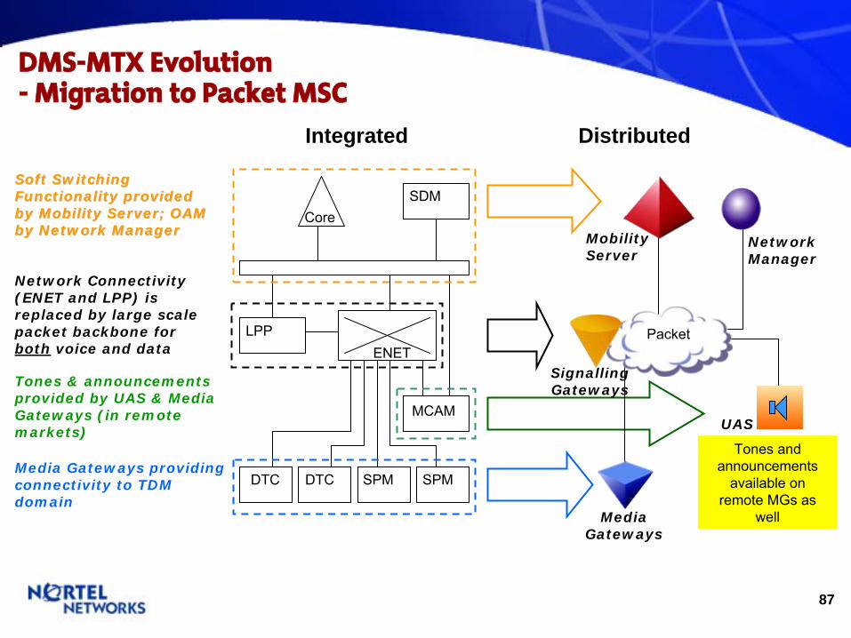
Tones & announcements provided by UAS & Media Gateways (in remote markets)
Integrated Distributed
DMS-MTX Evolution
-
Migration to Packet MSC
MobilityServer
Soft Switching Soft Switching Functionality provided Functionality provided by Mobility Server; OAM by Mobility Server; OAM by Network Managerby Network Manager
NetworkManager
ENET
MediaGateways
Media Gateways providing connectivity to TDM domain
Tones and announcements
available on remote MGs
as well
Network Connectivity (ENET and LPP) is replaced by large scale packet backbone for both voice and data
Packet
SignallingGateways

88
MTX Frame –
Line Up Before Packet
BIP
Frame 2 Frame 3BIP
CPDC(Power)
BIP
Frame 1 Frame 5BIP
LIS 0LMS
LIS 2LIS 1
MS 1MS 0
XA-Core
ENET 1ENET 0
Will become…SoftswitchFrame 8
MTMBIP
OAU
Frame 6BIP
LIS 0LMS
LIS 2LIS 1
BIP
SPM
Will become...Media Gateway
Frame 9BIP
Frame 10
SPM
SPM
BIP
SPM
SPM
SPM
BIP
Frame 12
SPM
SPM
BIP
Frame 13
SPM
SPM
BIP
Frame 14
SPM
SPM
BIP
Frame 15
SPM
SPM
BIP
Frame 29
SPM
SPM
…
ENET 0ENET 1
Frame 4BIP
ENET 1ENET 0
ENET 0ENET 1 SDM
BIP
I/O
Frame 7
Will become…OAM
Frame 11
89
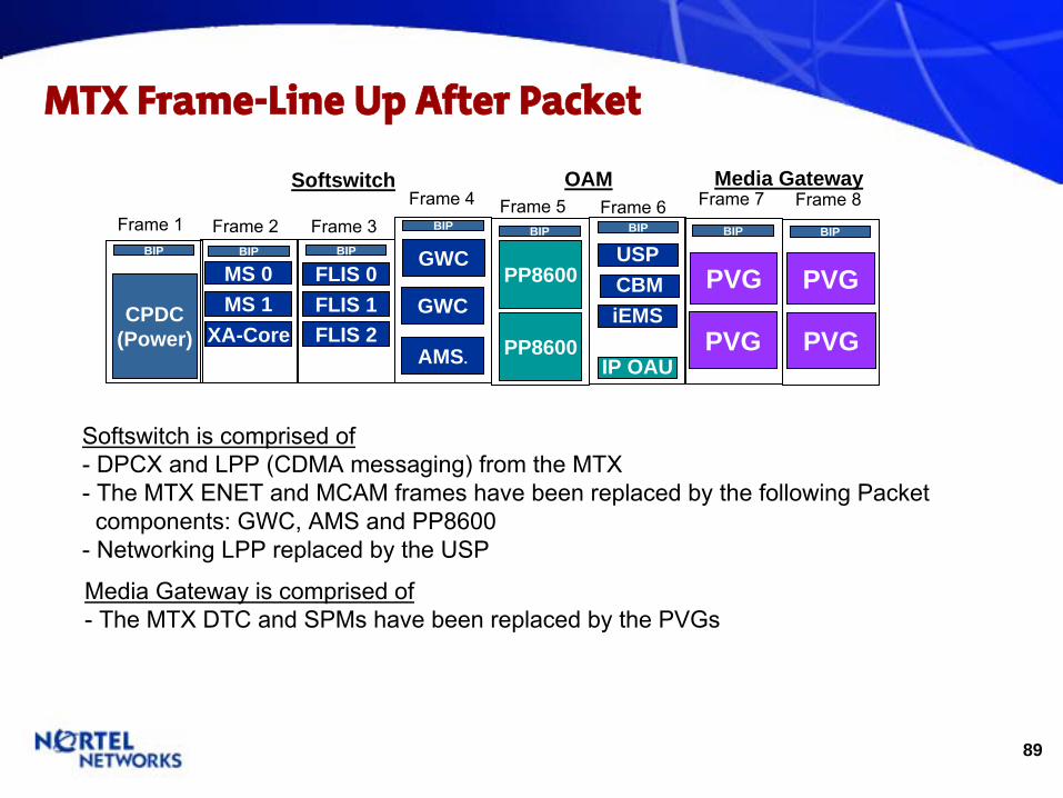
MTX Frame-Line Up After Packet
BIP
Frame 2
CPDC(Power)
BIP
Frame 1
Media Gateway
MS 1MS 0
Softswitch OAM
PP8600
Frame 5 Frame 6BIPBIP
PP8600
BIP
Frame 4
GWC
AMS.
BIP
Frame 7
PVG
PVGGWC
BIP
Frame 8
PVG
PVG
Frame 3BIP
FLIS 1FLIS 0
FLIS 2
USP
Softswitch
is comprised of
-
DPCX and LPP (CDMA messaging) from the MTX
-
The MTX ENET and MCAM frames have been replaced by the following Packet components: GWC, AMS and PP8600
-
Networking LPP replaced by the USP
XA-Core
Media Gateway is comprised of
-
The MTX DTC and SPMs
have been replaced by the PVGs
IP OAU
CBMiEMS
90
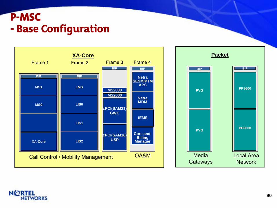
P-MSC -
Base Configuration
Frame 2XA-Core
Frame 1 Frame 3
BIP
MS0
XA-Core
MS1
BIP
LIS0
LIS2
LMS
LIS1
PVG
BIP
PVG
MediaGateways
PP8600
BIP
PP8600
Local AreaNetwork
Call Control / Mobility Management
BIP
MS2000
cPCI(SAM21)GWC
cPCI(SAM16)USP
MS2000
NetraSESM/PTM
APS
BIP
Frame 4
NetraMDM
OA&M
iEMS
Core and Billing
Manager
Packet
92
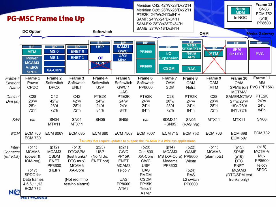
PG-MSC Frame Line Up
DC Option
BIP
PP8600
BIPBIP
SPMOr DTC
PowerMCAM3And/OrSPDC
BIP
Media Gateway
NetraSESM/PTM
RAS
BIP BIP
PVGMTMBIP
CSDM
BIP
I/OExpansion
BIPBIP
MS 1MS 0
XA-Core
ENET 1ENET 0
NetraMDM
In NOC
PP8600
Softswitch OAM
BIPSAM21GWCUASMisc.
NetraAPS
USP
FLPPor
Frame 1Power
CPDC
C2828”w28”d72”h
n/a
ECM 706ECM 730
(p11)MCAM3(power &IOM-req)
(p17)SPDC for
Data frames4,5,6,11,12ECM 772
Frame # Element
Name
CabinetDim (in)
S/W
ECM
Inter-Connects(ref V1.8)
Frame 2 Softswitch
DPCX
C4242”w28”d72”h
SN04MTX11
ECM 806?
(p12)MCAM3CSDMENET
PP8600
(HLIP)
Frame 3 Softswitch
ENET
C4242”w28”d72”h
SN04MTX11
ECM 635
(p13)DTC/SPM
(test trunks/
DTC mux)MCAM3XA-Core
{Not req
iff
no test/no alarms}
Frame 4 Softswitch
USP
PTE2K24”w24”d84”h
SN05
ECM 680
(p23)USP
(No NIUs, ENET opt)
Frame 5 Softswitch
GWC / UAS
PTE2K24”w24”d84”h
SN05
ECM 756?
(p21)GWC
PP15KENET
MCAM3Telco ?
UASPP8600ATM?
Frame 6 Softswitch
PP8600
PTE2K24”w24”d84”h
n/a
ECM 760?
(p20)Con 600XA-Core
GWCUSPUAS
PMDMCSDMPP15KTelco?ATM?
Frame 7 OAM
SDM
C2828”w28”d72”h
SDMX11~SN05
ECM 715
(p14)MCAM3
MS (XA-Core)ModemsPP8600
Frame 8 OAM
Netra
PTE2K24”w24”d84”h
SN05(RAS n/a)
ECM 752
(p22)OAME
PP8600Wkstn
(p24)RAS
L2 switchPP8600
Frame 9 OAM
MTM
C2828”w28”d72”h
MTX11
ECM 706
(p11)MCAM3
(alarm pts)
Frame 10 OAM
SPME (or) MCTM-V
SAME/MCTMV27”w/28”w18”d/28”d84”h/72”h
MTX11
ECM 698ECM 597
(p15)SPME(p16)DTC
ENETMCAM3
{DTC/SPM test trunks only}
Frame 11 MG
PVG (PP15K)
PTE2K24”w24”d84”h
SN06
ECM 732
(p18)MCTM-V
MuxPP8600Telco?SPDC
Frame 12SN06
ECM 752(p19)
PP8600
Meridian C42: 42”Wx28”Dx72”HMeridian C28: 28”Wx28”Dx72”HPTE2K: 24”Wx24”Dx84”HSAMF: 24”Wx24”Dx84”HSAM-FX: 28”Wx28”Dx84”HSAME: 27”Wx18”Dx84”H
MTM
?=ECMs that require updates to support the PG-MSC in a Wireless applications

93
P-MSC -
Is There Packet in Your Network’s Future? Network Fit
•
Switch−
At or near capacity−
All Nortel MSCs
–
OK −
Other ANSI-41 MSCs – OK −
MSC Mix – OK −
IOS –
OK
•
HLR / Gateway Combo−
More efficient routing−
Optimal use of capacity−
Packet interface to HLR
•
Network−
Regional or urban area with high inter-switch traffic
−
Call model•
High land to land•
High land to mobile
−
High IMT trunking−
High leased line fees−
Underutilized optical backbone−
CDMA/TDMA/AMPS
PSTN
Packet Network:Voice &
Signaling/Data
PDSN/FAPDSN/HA
MTXXA-Core
MTXXA-Core
MSC
DS1
BSC
DS1
BSCHLR
DS1
BSC
SS7 GW
MGMG
Aspen/H.248
ANSI-41
SS7 / ANSI-41
SS7 / ANSI-41
ANSI-41
BearerSignalingTDMPacket
PG-MSCAspen/H.248

94
Processing2 to 10 PE
I/O HIOP PE
Memory
PEHIOP ....
……
Serial Bus
IP
PG-MSCCS2K -
XA-Core
•
Portfolio - Wireline DPCX
•
Structure - Base DPCX XA-Core
•
Capacities - Controls legacy peripherals in hybrid
configurations - Provides packet control interface via HIOPs - Optimized for call processing - XA-Core 3+1 - BHCA = 1.2M, 165K ports
95
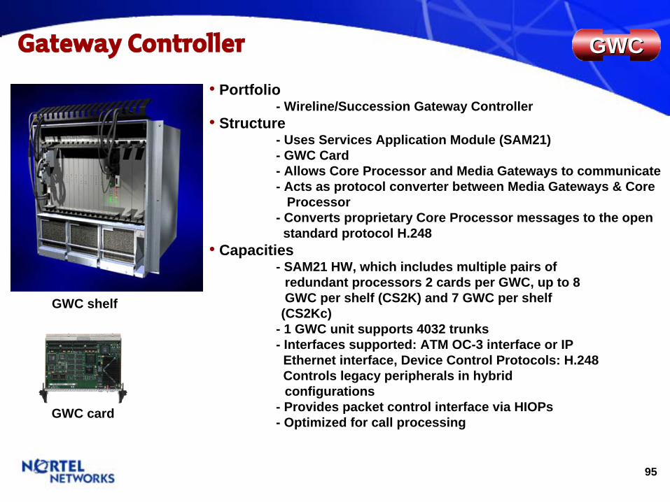
Gateway Controller GWCGWC
GWC card
GWC shelf
•
Portfolio - Wireline/Succession Gateway Controller
•
Structure - Uses Services Application Module (SAM21) - GWC Card - Allows Core Processor and Media Gateways to communicate - Acts as protocol converter between Media Gateways & Core
Processor - Converts proprietary Core Processor messages to the open standard protocol H.248
•
Capacities - SAM21 HW, which includes multiple pairs of
redundant processors 2 cards per GWC, up to 8 GWC per shelf (CS2K) and 7 GWC per shelf
(CS2Kc) - 1 GWC unit supports 4032 trunks - Interfaces supported: ATM OC-3 interface or IP
Ethernet interface, Device Control Protocols: H.248 Controls legacy peripherals in hybrid configurations
- Provides packet control interface via HIOPs - Optimized for call processing
96
•
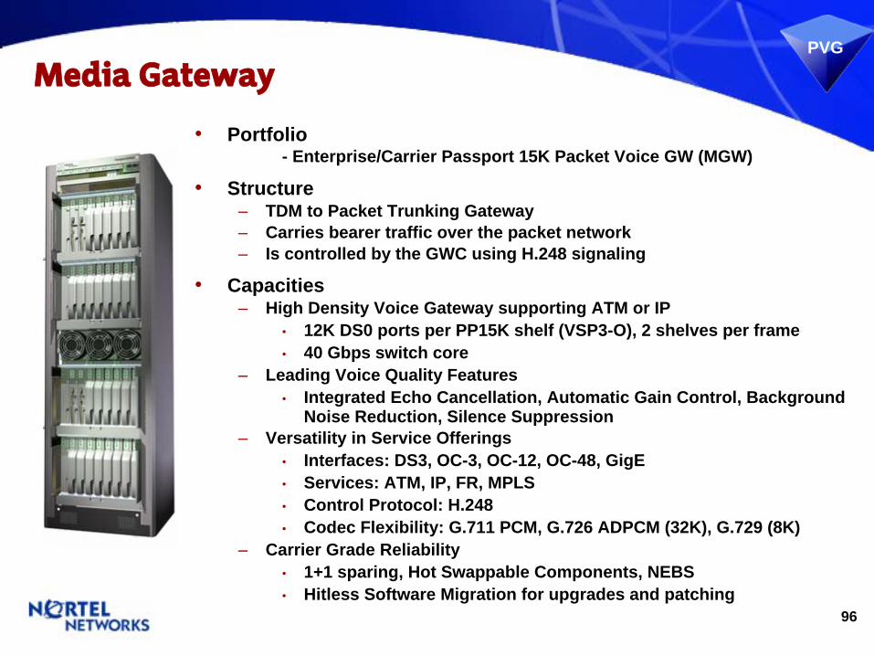
Portfolio - Enterprise/Carrier Passport 15K Packet Voice GW (MGW)
•
Structure–
TDM to Packet Trunking Gateway–
Carries bearer traffic over the packet network–
Is controlled by the GWC using H.248 signaling
•
Capacities–
High Density Voice Gateway supporting ATM or IP•
12K DS0 ports per PP15K shelf (VSP3-O), 2 shelves per frame•
40 Gbps switch core–
Leading Voice Quality Features•
Integrated Echo Cancellation, Automatic Gain Control, Background Noise Reduction, Silence Suppression
–
Versatility in Service Offerings•
Interfaces: DS3, OC-3, OC-12, OC-48, GigE•
Services: ATM, IP, FR, MPLS•
Control Protocol: H.248•
Codec Flexibility: G.711 PCM, G.726 ADPCM (32K), G.729 (8K)–
Carrier Grade Reliability•
1+1 sparing, Hot Swappable Components, NEBS•
Hitless Software Migration for upgrades and patching
PVG
Media Gateway

97
Universal Signaling PointUSP
•
Portfolio - Wireline/Succession (USP)
•
Structure–
Enables interworking of SS7 and Packet Telephony networks
•
Capacities–
ANSI and ITU SS7 Support•
V.35 and DS0 Low speed signaling interfaces
•
DS1 low speed channelized interfaces
•
DS1 ATM & IP High Speed Signaling links
–
IETF SIGTRAN Support•
SIGTRAN (M3UA, M2UA/SCTP)–
Carrier Grade•
Fully redundant architecture•
Hot swappable components•
NEBS Level 3 certification
98
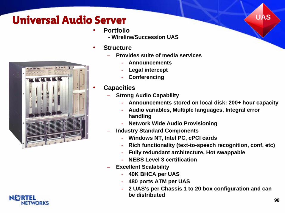
Universal Audio Server UAS
•
Portfolio - Wireline/Succession UAS
•
Structure–
Provides suite of media services•
Announcements•
Legal intercept•
Conferencing
•
Capacities–
Strong Audio Capability•
Announcements stored on local disk: 200+ hour capacity•
Audio variables, Multiple languages, Integral error handling
•
Network Wide Audio Provisioning–
Industry Standard Components•
Windows NT, Intel PC, cPCI cards•
Rich functionality (text-to-speech recognition, conf, etc)•
Fully redundant architecture, Hot swappable•
NEBS Level 3 certification–
Excellent Scalability•
40K BHCA per UAS •
480 ports ATM per UAS •
2 UAS's per Chassis 1 to 20 box configuration and can be distributed
99
Communication Server LAN
TopChassis
BottomChassis
•
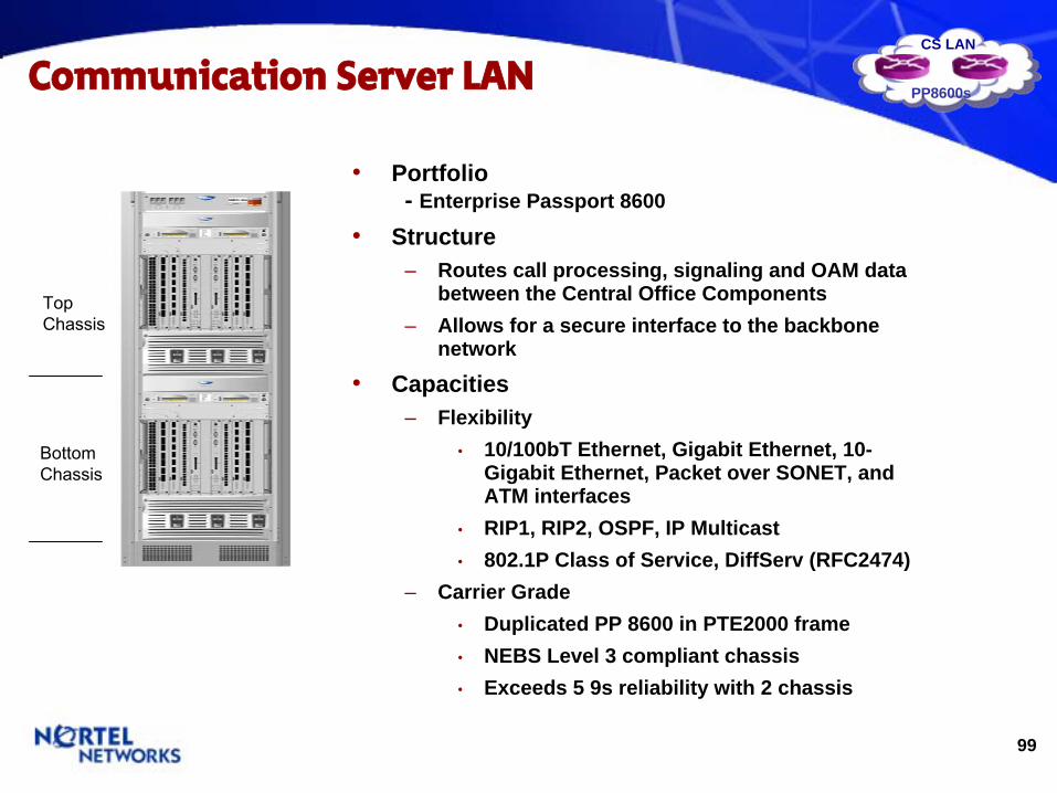
Portfolio - Enterprise Passport 8600
•
Structure–
Routes call processing, signaling and OAM data between the Central Office Components
–
Allows for a secure interface to the backbone network
•
Capacities–
Flexibility•
10/100bT Ethernet, Gigabit Ethernet, 10- Gigabit Ethernet, Packet over SONET, and ATM interfaces
•
RIP1, RIP2, OSPF, IP Multicast•
802.1P Class of Service, DiffServ (RFC2474)–
Carrier Grade•
Duplicated PP 8600 in PTE2000 frame•
NEBS Level 3 compliant chassis•
Exceeds 5 9s reliability with 2 chassis
CS LAN
PP8600s

100
Wireless Packet Portfolio -
Packet Data Network (EVDO)

101
1xRTT BTS1xEV-DO AP BSC
1xRTT BTS1xEV-DO AP
PDSN
MSC
PDN
PSTNCircuit Voice & Data World
Packet DataWorld
PDSN AAAServer
Carrier IP Internet
CDMA Packet Data Network- EVDO
•
Add 1xEV-DO Module (DOM) to Metrocell –
Separate multiple T1/E1 backhaul to support high speed data services–
Share GPS receiver & antenna, MFRM, radio antenna, duplexer with
Metrocell
•
Add 1xEV-DO DO-Radio Network Controller (DO-RNC)–
Co-located with BSC–
Interface with PDSN via open R-P, share core network elements (I.e. PDSN AAA server) with 1xRTT network
•
Add 1xEV-DO DO-EMS–
Co-located with BSC
1xRTT Backhaul
Metrocell BTS & 1xEV-DO AP
1xEV-DOModule (DOM)
1xEV DO Backhaul
1xEV-DODO-EMS
1xEV-DODO-RNC
IWF
AN-AAA
T1 Concentrator
102
CDMA Portfolio Overview-
Packet Data: BPS2000
•
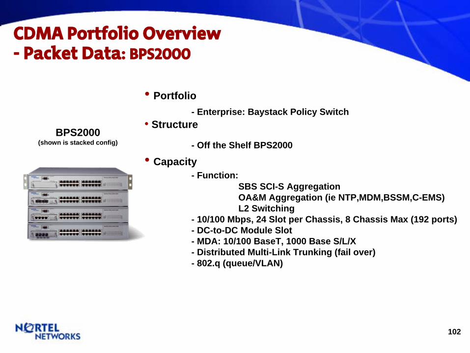
Portfolio - Enterprise: Baystack Policy Switch
•
Structure
- Off the Shelf BPS2000
•
Capacity - Function:
SBS SCI-S Aggregation OA&M Aggregation (ie NTP,MDM,BSSM,C-EMS) L2 Switching
- 10/100 Mbps, 24 Slot per Chassis, 8 Chassis Max (192 ports) - DC-to-DC Module Slot - MDA: 10/100 BaseT, 1000 Base S/L/X - Distributed Multi-Link Trunking (fail over) - 802.q (queue/VLAN)
BPS2000 (shown is stacked config)
103
CDMA Portfolio Overview-
Packet Data: PP8600
•
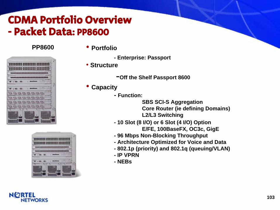
Portfolio - Enterprise: Passport
•
Structure
-Off the Shelf Passport 8600
•
Capacity - Function:
SBS SCI-S Aggregation Core Router (ie defining Domains) L2/L3 Switching
- 10 Slot (8 I/O) or 6 Slot (4 I/O) Option E/FE, 100BaseFX, OC3c, GigE
- 96 Mbps Non-Blocking Throughput - Architecture Optimized for Voice and Data - 802.1p (priority) and 802.1q (queuing/VLAN) - IP VPRN - NEBs
PP8600

104
CDMA Portfolio Overview-
Packet Data: Contivity
•
Portfolio - Enterprise: Contivity
•
Structure
- Off the Shelf 600
•
Capacity - Function
Nortel Access (eg Maintenance) - Smallest capacity/lowest cost product to provide secure
remote access for Nortel OAM monitoring - 600 supports up to 50 VPN Tunnels
Contivity600
105
CDMA Portfolio Overview-
Packet Data: Passport 7000 (DOM Aggregation)
•
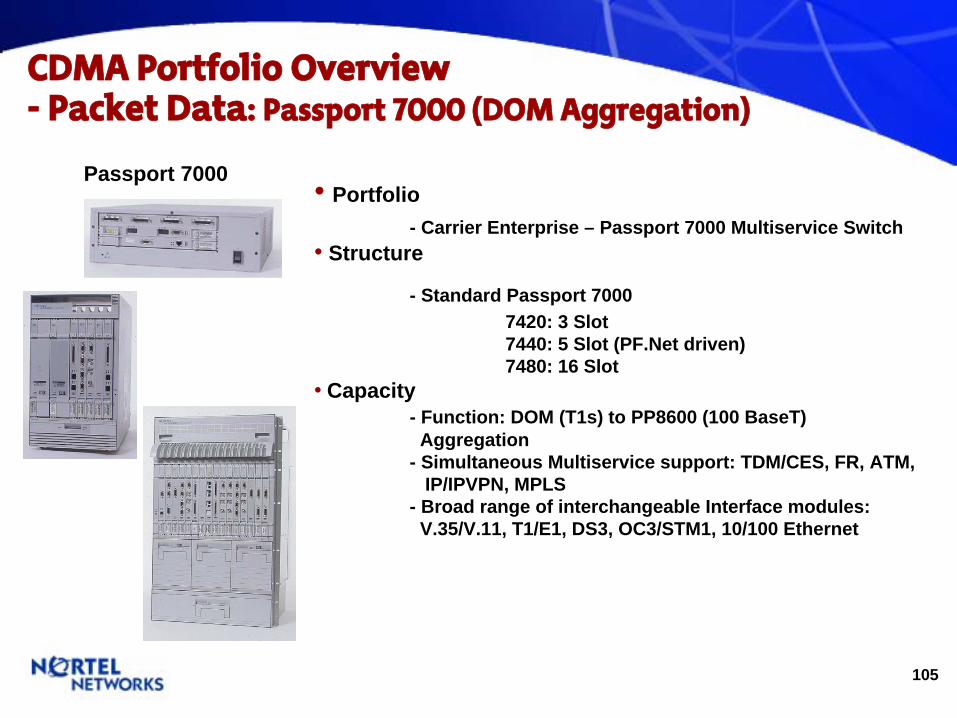
Portfolio - Carrier Enterprise – Passport 7000 Multiservice Switch
•
Structure
- Standard Passport 7000 7420: 3 Slot 7440: 5 Slot (PF.Net driven) 7480: 16 Slot
•
Capacity - Function: DOM (T1s) to PP8600 (100 BaseT)
Aggregation - Simultaneous Multiservice support: TDM/CES, FR, ATM,
IP/IPVPN, MPLS - Broad range of interchangeable Interface modules:
V.35/V.11, T1/E1, DS3, OC3/STM1, 10/100 Ethernet
Passport 7000

106
CDMA Portfolio Overview-
Packet Data: EdgeLink
(DOM Aggregation)
•
Portfolio - 3rd Party Supplier – Telco Systems
•
Structure
- Standard M1-3 Mux for T1 to DS-3 Aggregation•Capacity
- Function DOM(T1) to Shasta(DS3) Aggregation - Up to 112 T1 back hauls = EL-100
Over 112 T1 back hauls = EH-100 (252max)•
Issue - 3rd Party Supplier; Telco Systems, EdgeLink Product
Family. Nortel does not have a M1-3 Mux (T1-DS3) Solution.
EH-100
EL-100
107
CDMA Portfolio Overview-
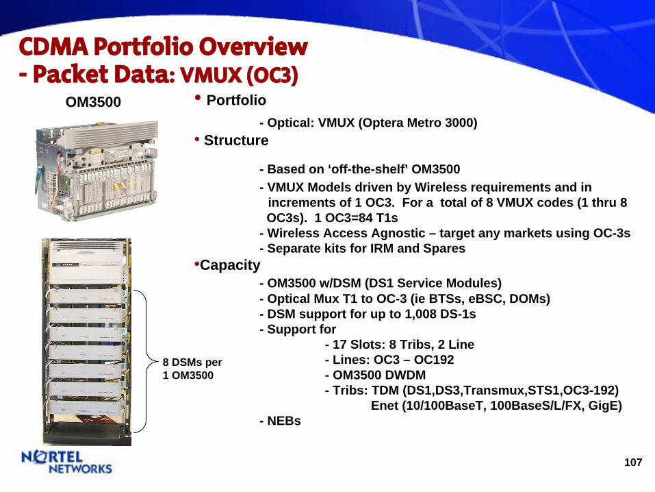
Packet Data: VMUX (OC3)
•
Portfolio - Optical: VMUX (Optera Metro 3000)
•
Structure
- Based on ‘off-the-shelf’ OM3500 - VMUX Models driven by Wireless requirements and in
increments of 1 OC3. For a total of 8 VMUX codes (1 thru 8 OC3s). 1 OC3=84 T1s
- Wireless Access Agnostic – target any markets using OC-3s - Separate kits for IRM and Spares
•Capacity - OM3500 w/DSM (DS1 Service Modules) - Optical Mux T1 to OC-3 (ie BTSs, eBSC, DOMs) - DSM support for up to 1,008 DS-1s - Support for
- 17 Slots: 8 Tribs, 2 Line - Lines: OC3 – OC192 - OM3500 DWDM - Tribs: TDM (DS1,DS3,Transmux,STS1,OC3-192)
Enet (10/100BaseT, 100BaseS/L/FX, GigE) - NEBs
OM3500
8 DSMs per 1 OM3500

108
CDMA Portfolio Overview-
Packet Data: VMUX (SDH)
•
Portfolio - Optical: VMUX (Optical Multiservice Edge – OME 6500)
•
Structure
- Based on ‘off-the-shelf’ OME 6500 - VMUX based Models driven in increments of STM-1 - VMUX Models driven by Wireless requirements and in
increments of STM-1. - Wireless Access Agnostic – target any markets using SDH - Separate kits for IRM and Spares
•Capacity - 2 per Bay, 8 STM-1, 504 E1s - NEBs
•
Issues - VMUX models pending (1Q05)
OME 6500
OME 6500
109
CDMA Portfolio Overview-
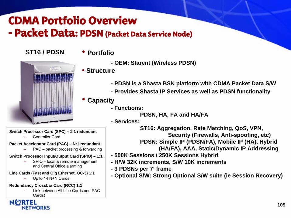
Packet Data: PDSN (Packet Data Service Node)
•
Portfolio - OEM: Starent (Wireless PDSN)
•
Structure
- PDSN is a Shasta BSN platform with CDMA Packet Data S/W - Provides Shasta IP Services as well as PDSN functionality
•
Capacity - Functions:
PDSN, HA, FA and HA/FA - Services:
ST16: Aggregation, Rate Matching, QoS, VPN, Security (Firewalls, Anti-spoofing, etc)
PDSN: Simple IP (PDSN/FA), Mobile IP (HA), Hybrid (HA/FA), AAA, Static/Dynamic IP Addressing
- 500K Sessions / 250K Sessions Hybrid - H/W 32K increments, S/W 10K increments - 3 PDSNs per 7’ frame - Optional S/W: Strong Optional S/W suite (ie Session Recovery)
ST16 / PDSN
Switch Processor Card (SPC) – 1:1 redundant–
Controller Card
Packet Accelerator Card (PAC) – N:1 redundant–
PAC –
packet processing & forwarding
Switch Processor Input/Output Card (SPIO) – 1:1–
SPIO –
local & remote management and Central Office alarming
Line Cards (Fast and Gig Ethernet, OC-3) 1:1–
Up to 14 N+N Cards
Redundancy Crossbar Card (RCC) 1:1–
Link between All Line Cards and PAC Cards)
110
CDMA Portfolio Overview-
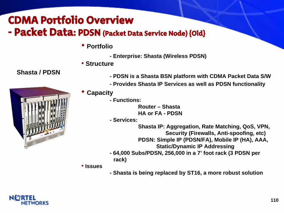
Packet Data: PDSN (Packet Data Service Node) {Old}
•
Portfolio - Enterprise: Shasta (Wireless PDSN)
•
Structure
- PDSN is a Shasta BSN platform with CDMA Packet Data S/W - Provides Shasta IP Services as well as PDSN functionality
•
Capacity - Functions:
Router – Shasta HA or FA - PDSN
- Services: Shasta IP: Aggregation, Rate Matching, QoS, VPN,
Security (Firewalls, Anti-spoofing, etc) PDSN: Simple IP (PDSN/FA), Mobile IP (HA), AAA,
Static/Dynamic IP Addressing - 64,000 Subs/PDSN, 256,000 in a 7’ foot rack (3 PDSN per
rack)•
Issues - Shasta is being replaced by ST16, a more robust solution
Shasta / PDSN
111
CDMA Portfolio Overview-
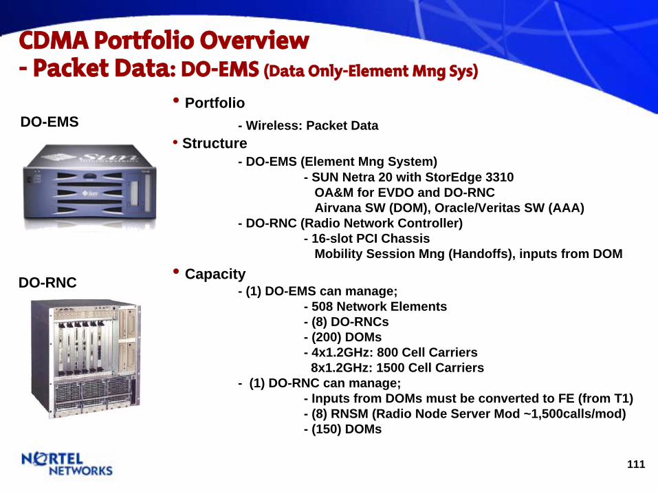
Packet Data: DO-EMS (Data Only-Element Mng
Sys)
•
Portfolio - Wireless: Packet Data
•
Structure - DO-EMS (Element Mng System)
- SUN Netra 20 with StorEdge 3310 OA&M for EVDO and DO-RNC Airvana SW (DOM), Oracle/Veritas SW (AAA)
- DO-RNC (Radio Network Controller) - 16-slot PCI Chassis
Mobility Session Mng (Handoffs), inputs from DOM•
Capacity
- (1) DO-EMS can manage; - 508 Network Elements - (8) DO-RNCs - (200) DOMs - 4x1.2GHz: 800 Cell Carriers 8x1.2GHz: 1500 Cell Carriers
- (1) DO-RNC can manage; - Inputs from DOMs must be converted to FE (from T1) - (8) RNSM (Radio Node Server Mod ~1,500calls/mod) - (150) DOMs
DO-RNC
DO-EMS
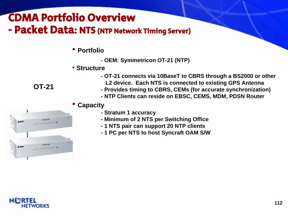
112
CDMA Portfolio Overview-
Packet Data: NTS (NTP Network Timing Server)
•
Portfolio - OEM: Symmetricon OT-21 (NTP)
•
Structure - OT-21 connects via 10BaseT to CBRS through a BS2000 or other
L2 device. Each NTS is connected to existing GPS Antenna - Provides timing to CBRS, CEMs (for accurate synchronization) - NTP Clients can reside on EBSC, CEMS, MDM, PDSN Router
•
Capacity - Stratum 1 accuracy - Minimum of 2 NTS per Switching Office - 1 NTS pair can support 20 NTP clients - 1 PC per NTS to host Syncraft OAM S/W
OT-21

113
CDMA Packet Data Network Topology- EVDO, cdma2000
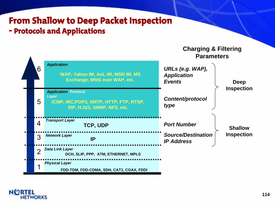
114
From Shallow to Deep Packet Inspection
-
Protocols and Applications
FDD-TDM, FDD-CDMA, SDH, CAT1, COAX, FDDI
Shallow Inspection
DCH, SLIP, PPP, ATM, ETHERNET, MPLS
IP
TCP, UDP
ICMP, IRC,POP3, SMTP, HTTP, FTP, RTSP, SIP, H.323, SNMP, NFS, etc.
WAP, Yahoo IM, AoL IM, MSN IM, MS Exchange, MMS over WAP, etc.
Physical Layer
Data Link Layer
Network Layer
Transport Layer
Application Protocol Layer
Application
Source/Destination IP Address
Port Number
Content/protocol type
URLs (e.g. WAP), Application Events Deep
Inspection
Charging & Filtering Parameters
6
5
4
3
2
1
115
Packet Network: MAC & IPPCMAC Site A site which contains a MAC Cluster but not an IPPC Cluster
IPPC Site A site containing an IPPC Cluster and usually a MAC Cluster
MAC, IPPC, NMC Clusters Logical groupings of equipment at the same or different locations MAC - ‘Metro Aggregation Cluster’ - Provides aggregation of traffic from SCI-S cards, MTX, BSC/eBSC IPPC - ‘Internet Peering Point Cluster’ - Provides an internet access point for traffic - Standalone HA, Contivity, Firewall, Edge Router, etc - Can be co-located with MAC cluster NMC - ‘Network Management Cluster’ - Provides network management servers for the entire network

116
CDMA 1xRTT / 1xEVDO -
Topology Framework
MTX
MAC
IPPC
intranet
MAC
MAC
MTX
MTX
MTX
MTX
MTX
MTX
PSTN
Individual PSTN networks require individual IPPCs
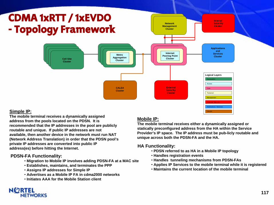
117
Logical Layers Aggregation
Access
Core
Management
External / Security
Transport
Applications / Services
CALEA
External Security Cluster
Applications and
Services Cluster
Network
Management Cluster
Network
Management Cluster
Internal
Security Cluster
Internet Peering Point
ClusterInternet
Peering Point Cluster
CALEA Cluster
Cell Site Cluster Cell Site
Cluster Cell Site Cluster Cell Site
Cluster
Metro
Aggregation Cluster
Metro
Aggregation Cluster
MetroAggregation
Cluster
The Design Group [2Q20] is responsible for the software design, network architecture, and product evolution of CDMA 3G Shasta BSN components. Recommendations for product configuration are based on Design's suggestions.
HA Functionality:• PDSN referred to as HA in a Mobile IP topology• Handles registration events• Handles tunneling mechanisms from PDSN-FAs• Applies IP Services to the mobile terminal while it is registered• Maintains the current location of the mobile terminal
CDMA 1xRTT / 1xEVDO-
Topology Framework
Simple IP: The mobile terminal receives a dynamically assigned address from the pools located on the PDSN. It is recommended that the IP addresses in the pool are publicly routable and unique. If public IP addresses are not available, then another device in the network must run NAT (Network Address Translation) in order that the PDSN pool’s private IP addresses are converted into public IP address(es) before hitting the Internet.
Mobile IP:The mobile terminal receives either a dynamically assigned or statically preconfigured address from the HA within the Service Provider’s IP space. The IP address must be pub-licly routable and unique across both the PDSN-FA and the HA.
PDSN-FA Functionality:• Migration to Mobile IP involves adding PDSN-FA at a MAC site• Establishes, maintains, and terminates the PPP • Assigns IP addresses for Simple IP• Advertises as a Mobile IP FA in cdma2000 networks• Initiates AAA for the Mobile Station client
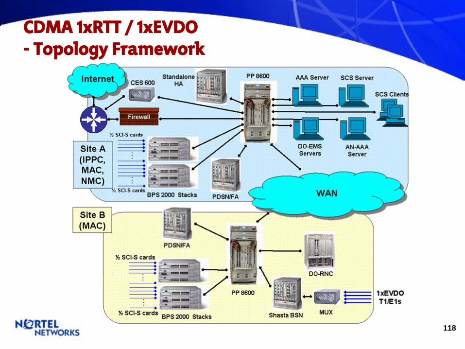
118
CDMA 1xRTT / 1xEVDO-
Topology Framework
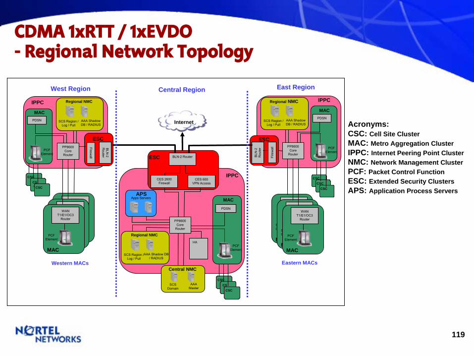
119
CDMA 1xRTT / 1xEVDO- Regional Network Topology
CSCCSC
CSCCS C
CSCCSC
CSCCSC
CSCCS C
CSCCSC
Internet
IPPC
BLN-2 Router
CES 600 VPN Access
CES 2600 Firewall
SCS Domain
AAA Master
Central NMC
Regional NMC
SCS Region / Log / Pull
AAA Shadow DB / RADIUS
Apps ServersAPS
HA
ESC
IPPC
PCF Element
PDSN
MAC
PP8600 Core
RouterSCI-S Cards
MAC
WAN T1/E1/OC3
Router
CSCCSC
CSCCSC
CSCCSC
SCI-S Cards
MAC
WAN T1/E1/OC3
Router
PCF Element
MAC
WAN T1/E1/OC3
Router
BLN
-2
Rou
ter
Fire
wal
l
ESCPP8600
Core Router
Regional NMC
SCS Region / Log / Pull
AAA Shadow DB / RADIUS
IPPC
PDSN
MAC
PCF Element
BLN-2
Router
Firewall
ESCPP8600
Core Router
Regional NMC
SCS Region / Log / Pull
AAA Shadow DB / RADIUS
PDSN
MAC
PCF Element
SCI-S Cards
MAC
WAN T1/E1/OC3
Router
SCI-S Cards
MAC
WAN T1/E1/OC3
Router
PCF Element
MAC
WAN T1/E1/OC3
Router
Central Region East RegionWest Region
Western MACs Eastern MACs
Acronyms:CSC: Cell Site ClusterMAC: Metro Aggregation ClusterIPPC: Internet Peering Point ClusterNMC: Network Management ClusterPCF: Packet Control FunctionESC: Extended Security ClustersAPS: Application Process Servers

120
CDMA Network- Security

121
Internet
PDN
BTS
SS7 PSTN
Management LAN/WAN
RemoteAccess
Data Center LAN
OAM Client
MTX/HLR MSC
AAAAN-AAA
App Servers
VPN GatewayCNM/CEMS/DO-EMS
1X BSC 1xEV-DO RNC
I/C/S-CSCFHSS
Home MMD
PDSN/HA/FA
Security Requires End-to-End Focus to Protect Traffic Planes
across the Infrastructure
Regulatory & Emergency Services
Layered Defense Approach to Wireless Networks -
Control, User and Management Planes
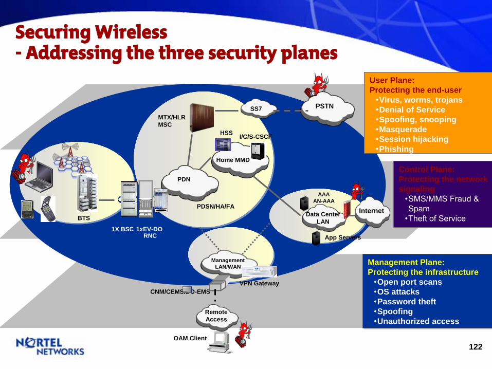
122
Internet
PDN
BTS
SS7 PSTN
Management LAN/WAN
RemoteAccess
Data Center LAN
OAM Client
MTX/HLR MSC
AAAAN-AAA
App Servers
VPN Gateway
Securing Wireless -
Addressing the three security planes
CNM/CEMS/DO-EMS
1X BSC 1xEV-DO RNC
User Plane:Protecting the end-user
•Virus, worms, trojans•Denial of Service•Spoofing, snooping•Masquerade•Session hijacking•Phishing
Management Plane:Protecting the infrastructure
•Open port scans•OS attacks•Password theft•Spoofing•Unauthorized access
Management Plane:Protecting the infrastructure
•Open port scans•OS attacks•Password theft•Spoofing•Unauthorized access
Control Plane:Protecting the network signaling
•SMS/MMS Fraud & Spam
•Theft of Service
I/C/S-CSCFHSS
Home MMD
PDSN/HA/FA

123
Internet
PDN
BTS
SS7 PSTN
Management LAN/WAN
RemoteAccess
Data Center LAN
OAM Client
MTX/HLR MSC
AAAAN-AAA
App Servers
VPN GatewayCNM/CEMS/DO-EMS
1X BSC 1xEV-DO RNC
I/C/S-CSCFHSS
Home MMD
PDSN/HA/FA
CDMA Secures User Planes Today
•
Encrypted MACID
Protection from spoofing•
Variable timeslot assignment and data rate
•
Downlink HARQ multiple sub-packets, early termination
•
Proprietary BSC and BTS BCN protocol
•
Proprietary DOM to DO-RNC interface
•
Encryption (IPSEC, VPN/VPRN, VLAN)
•
Per-user Stateful firewall•
Packet Filtering •
Deep packet inspection•
Traffic steering•
On-board CALEA
User Plane:Protecting the end-user
•Virus, worms, trojans•Denial of Service•Spoofing, snooping•Masquerade•Session hijacking•Phishing

124
Internet
PDN
BTS
SS7 PSTN
Management LAN/WAN
RemoteAccess
Data Center LAN
OAM Client
MTX/HLR MSC
AAAAN-AAA
App Servers
VPN GatewayCNM/CEMS/DO-EMS
1X BSC 1xEV-DO RNC
I/C/S-CSCFHSS
Home MMD
PDSN/HA/FA
•
Ingress Anti-spoofing•
Authentication – RADIUS, PAP/CHAP•
On-board CALEA•
Virtual Router – secured VPN•
Access control list on physical ports & per subscriber
•
Clone Detection Tool•
ESN Masking & Fraud Control•
Multiple Tumbling ESNs•
IS-41 Fraud Prevention•
Roamer Verification & Reinstatement•
Subscriber PIN based features•
VLR negative profile•
Proprietary BSC to BTS BCN protocol
•
Proprietary DOM to DO-RNC interface
•
EV-DO device authentication via AN-AAA protects DOS attack to PDSN
•
3GPP2 compliant data user authentication
Control Plane:Protecting the network signaling
•SMS/MMS Fraud & Spam
•Theft of Service
CDMA Secures Control Planes Today
•
IPSec Encryption (inter-domains)•
AKA authentication•
IPSec or TLS between UE & CSCF
SEC
125
CDMA Network- Power Provisioning Rules
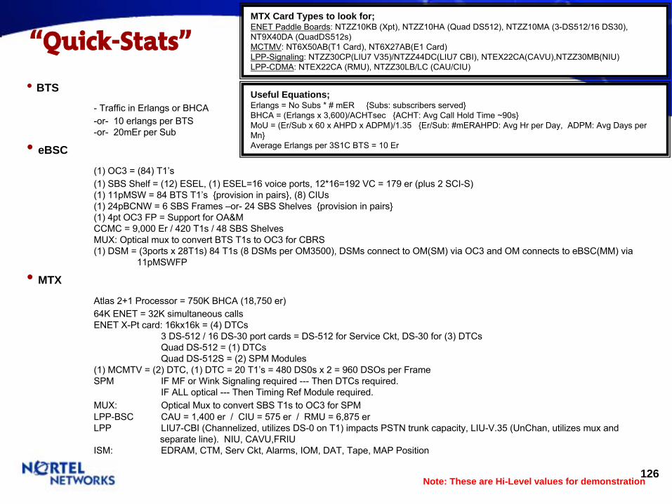
126
“Quick-Stats”
•
BTS
-
Traffic in Erlangs
or BHCA
-or-
10 erlangs
per BTS
-or-
20mEr per Sub
•
eBSC
(1) OC3 = (84) T1’s
(1) SBS Shelf = (12) ESEL, (1) ESEL=16 voice ports, 12*16=192 VC
= 179 er
(plus 2 SCI-S)
(1) 11pMSW = 84 BTS T1’s {provision in pairs}, (8) CIUs
(1) 24pBCNW = 6 SBS Frames –or-
24 SBS Shelves {provision in pairs}
(1) 4pt OC3 FP = Support for OA&M
CCMC = 9,000 Er
/ 420 T1s / 48 SBS Shelves
MUX: Optical mux
to convert BTS T1s to OC3 for CBRS
(1) DSM = (3ports x 28T1s) 84 T1s (8 DSMs
per OM3500), DSMs
connect to OM(SM) via OC3 and OM connects to eBSC(MM) via 11pMSWFP
•
MTX
Atlas 2+1 Processor = 750K BHCA (18,750 er)
64K ENET = 32K simultaneous calls
ENET X-Pt card: 16kx16k = (4) DTCs
3 DS-512 / 16 DS-30 port cards = DS-512 for Service Ckt, DS-30 for (3) DTCs
Quad DS-512 = (1) DTCs
Quad DS-512S = (2) SPM Modules
(1) MCMTV = (2) DTC, (1) DTC = 20 T1’s = 480 DS0s x 2 = 960 DSOs per Frame
SPM
IF MF or Wink Signaling required ---
Then DTCs
required. IF ALL optical ---
Then Timing Ref Module required.
MUX:
Optical Mux
to convert SBS T1s to OC3 for SPM
LPP-BSC
CAU = 1,400 er
/ CIU = 575 er
/ RMU = 6,875 er
LPP
LIU7-CBI (Channelized, utilizes DS-0 on T1) impacts PSTN trunk capacity, LIU-V.35 (UnChan, utilizes mux
and separate line). NIU, CAVU,FRIU
ISM:
EDRAM, CTM, Serv
Ckt, Alarms, IOM, DAT, Tape, MAP Position
Note: These are Hi-Level values for demonstration
MTX Card Types to look for; ENET Paddle Boards: NTZZ10KB (Xpt), NTZZ10HA (Quad DS512), NTZZ10MA (3-DS512/16 DS30), NT9X40DA (QuadDS512s)MCTMV: NT6X50AB(T1 Card), NT6X27AB(E1 Card)
LPP-Signaling: NTZZ30CP(LIU7 V35)/NTZZ44DC(LIU7 CBI), NTEX22CA(CAVU),NTZZ30MB(NIU)
LPP-CDMA: NTEX22CA (RMU), NTZZ30LB/LC (CAU/CIU)
Useful Equations; Erlangs
= No Subs * # mER
{Subs: subscribers served}BHCA = (Erlangs
x 3,600)/ACHTsec {ACHT: Avg
Call Hold Time ~90s}
MoU
= (Er/Sub x 60 x AHPD x ADPM)/1.35 {Er/Sub: #mERAHPD: Avg
Hr per Day, ADPM: Avg
Days per Mn}
Average Erlangs
per 3S1C BTS = 10 Er

127
Line Rates -
Cu to Optical
SONET SDH SONET SDH52 OC-1 STM-0 28 T1s or 1
T3 21 E1s
155 OC-3 STM-1 84 T1s or 3 T3/DS3s
63 E1s or 1 E4
466 OC-9622 OC-12 STM-4 4
STM-1336 T1s or 12 T3/DS3s
252 E1s or 4 E4s
933 OC-181244 OC-241866 OC-362488 OC-48 STM-16 4
STM-41344 T1s or 48 T3s
1008 E1s or 16 E4s
9953 0C-192 STM-64 5376 T1s or 192 T3s
4032 E1s or 64 E4s
43 T3/STS-12.048 E11.544 T10.064 DS-0 8bits * 8K
Speed (Mbps)
Signal level Channels