Embed Size (px)
Citation preview
© 2020 Power-Tronics, Inc.
The Power-Tronics XC4 Automatic Voltage Regulator is the latest upgrade for our commercial voltage regulator product line! The XC4 is capable of replacing other manufacturers' voltage regulators and can fit into extremely tight enclosures due to its small size! The XC4 is designed as a commercial product, ideal for installation in standby applications, portable generators, residential generators, and any application where the customer demands a simple, reliable, and durable regulator at a competitive price. The Revision A XC4 offers greater value with an onboard fuse to protect against overload or external faults! Simplicity and Reliability are important to the Power-Tronics brand, and all components used in the manufacture of our products are high-quality name-brand and engineered to withstand the continuous ratings advertised on our products. You can have confidence with a product designed and manufactured in the USA and backed by a factory One-Year Warranty! Based internally on the XR8 voltage regulator, the XC4 offers precise voltage regulation regardless of the connected load and ambient temperature. It incorporates an idle-protection circuit that automatically reduces voltage to prevent excessive rotor heating when the engine is idled. The XC4 uses the XR8’s patented electronic circuitry that automatically matches the regulator's response time to the generator exciter. This greatly speeds installation and eliminates guesswork. Because it only uses 4 wires for connection to the generator, it also makes quick replacement in the field possible! To ensure extreme durability and dependability, the XC4 is fully encapsulated in a heat-resistant polyester resin. Because of its strong design and fully encapsulated packaging, the XC4 is able to withstand extreme operating conditions that would damage most other voltage regulators. The XC4 is a direct upgrade for previous VP4, VP5, VR50, and VR250 voltage regulators.
Specifications
Input Voltage: 120 / 208 or 240vac Frequency: 50 or 60hz Voltage Regulation: ± .75% From NL to FL Parallel Operation: Yes Maximum Output Voltage: 52vdc @ 120vac input 105vdc @ 240vac input Continuous Output Voltage: 32vdc @ 120vac input 63vdc @ 240vac input Maximum Output Current: 5adc Minimum Field Resistance: 8Ω @ 32vdc output 16Ω @ 63vdc output Min Residual Build up Voltage: 3.5vac Under Frequency Protection: Yes, Idle speed reduction Physical Size: 4.1 x 2.1 x .75 in. Weight: 2.5 oz Fully Encapsulated: Yes Internal Fuse Type: GDB5A @ 250V Fast-Blow Remote Voltage Adjustment: No System Operating Indicator: No Optional Static Exciter Modules: No Optional External Controls: No
XC4 Commercial Series
Voltage Regulator Revision B
(From Serial # 625252)
2
For Technical Support: Visit our website at: www.power-tronics.com Call Us at: (830) 895-4700
Table of Contents Introduction and Functional Description:....................................................................3 Determining Which Hookup Configuration to Use:....................................................4 Common 12-Lead Generator Wiring Diagrams:..........................................................6 Use with PMGs, DPE, AUX, and Harmonic Winding Generators:..............................7 240V Hookup Connection:.............................................................................................8 120V Hookup Connection:.............................................................................................9 Installation Considerations:....................................................................................... 10 Initial Setup and Commissioning:...............................................................................10 Optional Power-Tronics Add On Modules:................................................................11 Conversion From Shunt-Wound to Solid-State Regulation:....................................12 Application Troubleshooting:......................................................................................13 Bench Check Procedures:...........................................................................................14 Installation Warranty Form:.........................................................................................15 Product Warranty Certificate:......................................................................................16
3
For Technical Support: Visit our website at: www.power-tronics.com Call Us at: (830) 895-4700
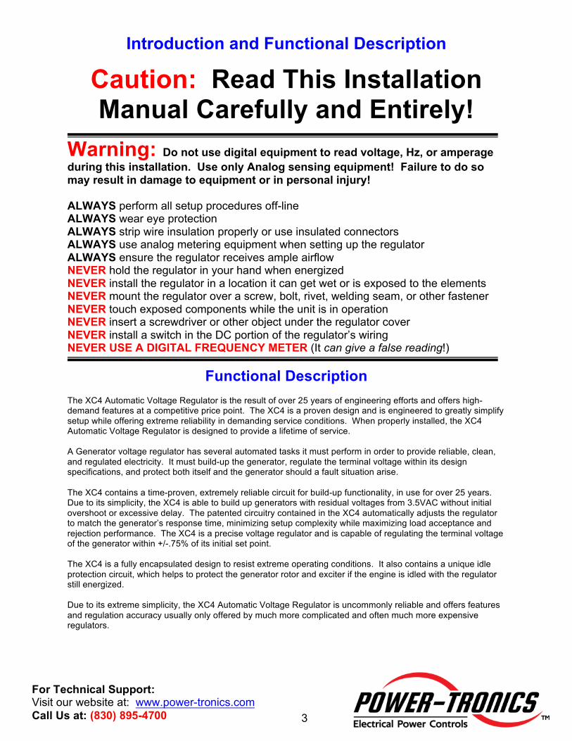
Introduction and Functional Description
Caution: Read This Installation Manual Carefully and Entirely!
Warning: Do not use digital equipment to read voltage, Hz, or amperage during this installation. Use only Analog sensing equipment! Failure to do so may result in damage to equipment or in personal injury! ALWAYS perform all setup procedures off-line ALWAYS wear eye protection ALWAYS strip wire insulation properly or use insulated connectors ALWAYS use analog metering equipment when setting up the regulator ALWAYS ensure the regulator receives ample airflow NEVER hold the regulator in your hand when energized NEVER install the regulator in a location it can get wet or is exposed to the elements NEVER mount the regulator over a screw, bolt, rivet, welding seam, or other fastener NEVER touch exposed components while the unit is in operation NEVER insert a screwdriver or other object under the regulator cover NEVER install a switch in the DC portion of the regulator’s wiring NEVER USE A DIGITAL FREQUENCY METER (It can give a false reading!)
Functional Description
The XC4 Automatic Voltage Regulator is the result of over 25 years of engineering efforts and offers high-demand features at a competitive price point. The XC4 is a proven design and is engineered to greatly simplify setup while offering extreme reliability in demanding service conditions. When properly installed, the XC4 Automatic Voltage Regulator is designed to provide a lifetime of service. A Generator voltage regulator has several automated tasks it must perform in order to provide reliable, clean, and regulated electricity. It must build-up the generator, regulate the terminal voltage within its design specifications, and protect both itself and the generator should a fault situation arise. The XC4 contains a time-proven, extremely reliable circuit for build-up functionality, in use for over 25 years. Due to its simplicity, the XC4 is able to build up generators with residual voltages from 3.5VAC without initial overshoot or excessive delay. The patented circuitry contained in the XC4 automatically adjusts the regulator to match the generator’s response time, minimizing setup complexity while maximizing load acceptance and rejection performance. The XC4 is a precise voltage regulator and is capable of regulating the terminal voltage of the generator within +/-.75% of its initial set point. The XC4 is a fully encapsulated design to resist extreme operating conditions. It also contains a unique idle protection circuit, which helps to protect the generator rotor and exciter if the engine is idled with the regulator still energized. Due to its extreme simplicity, the XC4 Automatic Voltage Regulator is uncommonly reliable and offers features and regulation accuracy usually only offered by much more complicated and often much more expensive regulators.

4
For Technical Support: Visit our website at: www.power-tronics.com Call Us at: (830) 895-4700
Determining Which Hookup Configuration to Use STOP! DO NOT use this product in combination with add-on products designed for UVR and XR series voltage regulators! Immediate voltage
runaway and potentially life-threatening conditions may occur!!! The XC4 Automatic Voltage Regulator is suitable for 2 different output ranges suitable for use on most brushless generators available on the market from past and present. It is necessary to choose the proper mode of operation for your generator in order to get the best regulation and fastest response time possible. To determine the proper connection for your generator you need to know any two of the following 3 specifications from the rating plate of your generator:
1: Exciter Field Voltage (in DC Volts) [Generally given in full load Voltage on nameplates] 2: Exciter Field Resistance (in Ohms) [See Note Below] 3: Exciter Field Amperage (in DC Amps) [Generally given in full load Amps on nameplates]
Using the specifications obtained from your generator exciter, select
120V or 240V Hookup from the list below:
• Exciter Field Resistance ≥16Ω & Exciter Full-Load Voltage ≤63VDC Use 240V Hookup Connection (See Page 8)
• Exciter Field Resistance ≥8Ω & Exciter Full-Load Voltage ≤32VDC
Use 120V Hookup Connection (See Page 10) Note about Field Resistance: • When measuring field resistance on a brushless generator, simply measure the
resistance of the exciter field through your field leads with a multimeter. • When measuring field resistance on a brush-type generator, measure the resistance
through both the field leads as well as directly on the slip rings themselves. The readings you obtain should ideally be the same, but no more than 1% difference. If you show more than 1% difference in reading your generator has brush and ring contact problems and will need cleaning or maintenance before installing the XC4. Failure to correct brush and ring contact problems will result in severe damage to the voltage regulator as well as possible PERMANENT damage to the slip rings themselves! NEVER use emery cloth, carborundum stones, “comm sticks”, or Tuner cleaner to dress or clean slip rings. They will make a bad problem much, much worse! Only use Garnet or Flint sandpaper and clean with a clean rag soaked with Acetone for best results!
5
For Technical Support: Visit our website at: www.power-tronics.com Call Us at: (830) 895-4700
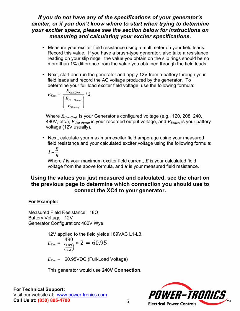
If you do not have any of the specifications of your generator’s exciter, or if you don’t know where to start when trying to determine your exciter specs, please see the section below for instructions on
measuring and calculating your exciter specifications.
• Measure your exciter field resistance using a multimeter on your field leads. Record this value. If you have a brush-type generator, also take a resistance reading on your slip rings: the value you obtain on the slip rings should be no more than 1% difference from the value you obtained through the field leads.
• Next, start and run the generator and apply 12V from a battery through your
field leads and record the AC voltage produced by the generator. To determine your full load exciter field voltage, use the following formula:
EExc. =
€
EGen.Conf .
EGen.Output
EBattery
"
# $ $
%
& ' '
*2
Where EGen.Conf. is your Generator’s configured voltage (e.g.: 120, 208, 240, 480V, etc.), EGen.Output is your recorded output voltage, and EBattery is your battery voltage (12V usually).
• Next, calculate your maximum exciter field amperage using your measured field resistance and your calculated exciter voltage using the following formula:
I = ER
Where I is your maximum exciter field current, E is your calculated field voltage from the above formula, and R is your measured field resistance.
Using the values you just measured and calculated, see the chart on the previous page to determine which connection you should use to
connect the XC4 to your generator. For Example: Measured Field Resistance: 18Ω Battery Voltage: 12V Generator Configuration: 480V Wye
12V applied to the field yields 189VAC L1-L3.
EExc. = 480$%&$'
∗ 2 = 60.95
EExc. = 60.95VDC (Full-Load Voltage) This generator would use 240V Connection.
6
For Technical Support: Visit our website at: www.power-tronics.com Call Us at: (830) 895-4700
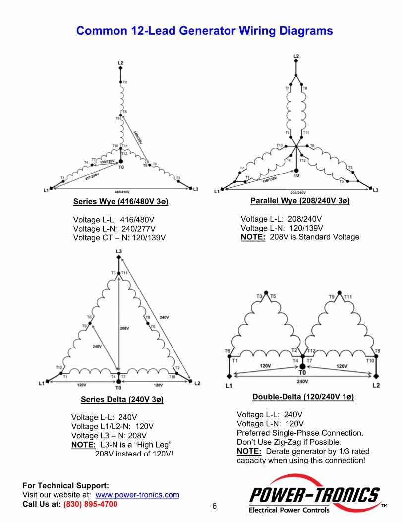
Common 12-Lead Generator Wiring Diagrams
Series Wye (416/480V 3ø) Voltage L-L: 416/480V Voltage L-N: 240/277V Voltage CT – N: 120/139V
Parallel Wye (208/240V 3ø) Voltage L-L: 208/240V Voltage L-N: 120/139V NOTE: 208V is Standard Voltage
Series Delta (240V 3ø) Voltage L-L: 240V Voltage L1/L2-N: 120V Voltage L3 – N: 208V NOTE: L3-N is a “High Leg” 208V instead of 120V!
Double-Delta (120/240V 1ø) Voltage L-L: 240V Voltage L-N: 120V Preferred Single-Phase Connection. Don’t Use Zig-Zag if Possible. NOTE: Derate generator by 1/3 rated capacity when using this connection!
7
For Technical Support: Visit our website at: www.power-tronics.com Call Us at: (830) 895-4700
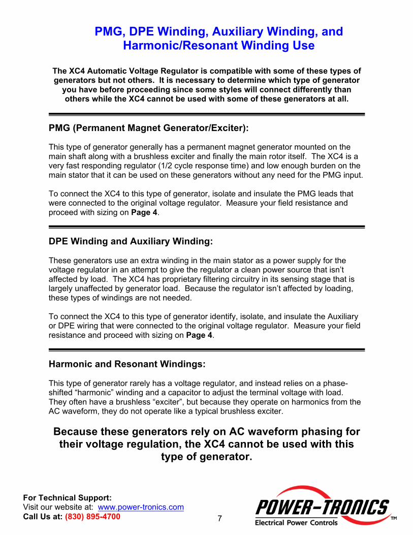
PMG, DPE Winding, Auxiliary Winding, and Harmonic/Resonant Winding Use
The XC4 Automatic Voltage Regulator is compatible with some of these types of generators but not others. It is necessary to determine which type of generator
you have before proceeding since some styles will connect differently than others while the XC4 cannot be used with some of these generators at all.
PMG (Permanent Magnet Generator/Exciter): This type of generator generally has a permanent magnet generator mounted on the main shaft along with a brushless exciter and finally the main rotor itself. The XC4 is a very fast responding regulator (1/2 cycle response time) and low enough burden on the main stator that it can be used on these generators without any need for the PMG input. To connect the XC4 to this type of generator, isolate and insulate the PMG leads that were connected to the original voltage regulator. Measure your field resistance and proceed with sizing on Page 4. DPE Winding and Auxiliary Winding: These generators use an extra winding in the main stator as a power supply for the voltage regulator in an attempt to give the regulator a clean power source that isn’t affected by load. The XC4 has proprietary filtering circuitry in its sensing stage that is largely unaffected by generator load. Because the regulator isn’t affected by loading, these types of windings are not needed. To connect the XC4 to this type of generator identify, isolate, and insulate the Auxiliary or DPE wiring that were connected to the original voltage regulator. Measure your field resistance and proceed with sizing on Page 4. Harmonic and Resonant Windings: This type of generator rarely has a voltage regulator, and instead relies on a phase-shifted “harmonic” winding and a capacitor to adjust the terminal voltage with load. They often have a brushless “exciter”, but because they operate on harmonics from the AC waveform, they do not operate like a typical brushless exciter. Because these generators rely on AC waveform phasing for
their voltage regulation, the XC4 cannot be used with this type of generator.
8
For Technical Support: Visit our website at: www.power-tronics.com Call Us at: (830) 895-4700
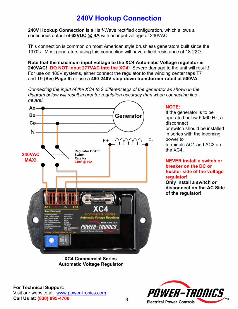
240V Hookup Connection
240V Hookup Connection is a Half-Wave rectified configuration, which allows a continuous output of 63VDC @ 4A with an input voltage of 240VAC. This connection is common on most American style brushless generators built since the 1970s. Most generators using this connection will have a field resistance of 18-22Ω. Note that the maximum input voltage to the XC4 Automatic Voltage regulator is 240VAC! DO NOT input 277VAC into the XC4! Severe damage to the unit will result! For use on 480V systems, either connect the regulator to the winding center taps T7 and T9 (See Page 6) or use a 480-240V step-down transformer rated at 500VA. Connecting the input of the XC4 to 2 different legs of the generator as shown in the diagram below will result in greater regulation accuracy than when connecting line-neutral.
XC4 Commercial Series Automatic Voltage Regulator
NOTE: If the generator is to be operated below 50/60 Hz, a disconnect or switch should be installed in series with the incoming power to terminals AC1 and AC2 on the XC4. NEVER install a switch or breaker on the DC or Exciter side of the voltage regulator! Only install a switch or disconnect on the AC Side of the regulator!
240VAC MAX!
Regulator On/Off Switch Rate for: 240V @ 10A
9
For Technical Support: Visit our website at: www.power-tronics.com Call Us at: (830) 895-4700
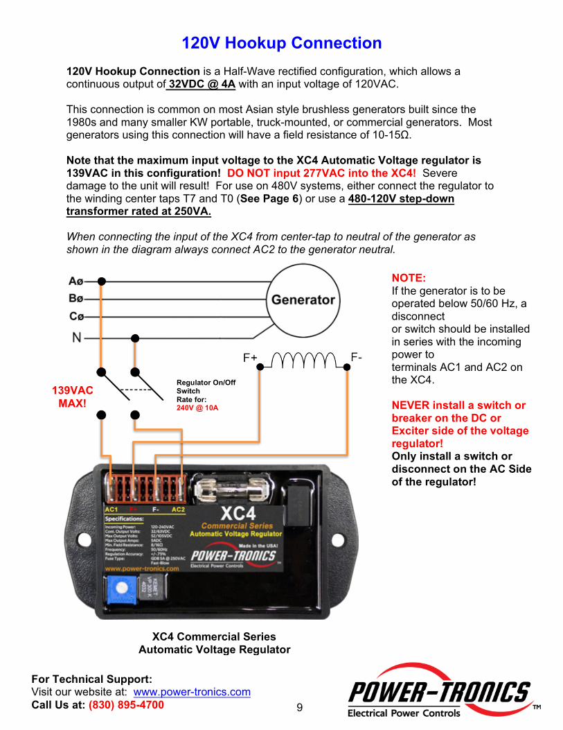
120V Hookup Connection
120V Hookup Connection is a Half-Wave rectified configuration, which allows a continuous output of 32VDC @ 4A with an input voltage of 120VAC. This connection is common on most Asian style brushless generators built since the 1980s and many smaller KW portable, truck-mounted, or commercial generators. Most generators using this connection will have a field resistance of 10-15Ω. Note that the maximum input voltage to the XC4 Automatic Voltage regulator is 139VAC in this configuration! DO NOT input 277VAC into the XC4! Severe damage to the unit will result! For use on 480V systems, either connect the regulator to the winding center taps T7 and T0 (See Page 6) or use a 480-120V step-down transformer rated at 250VA. When connecting the input of the XC4 from center-tap to neutral of the generator as shown in the diagram always connect AC2 to the generator neutral.
XC4 Commercial Series Automatic Voltage Regulator
NOTE: If the generator is to be operated below 50/60 Hz, a disconnect or switch should be installed in series with the incoming power to terminals AC1 and AC2 on the XC4. NEVER install a switch or breaker on the DC or Exciter side of the voltage regulator! Only install a switch or disconnect on the AC Side of the regulator!
139VAC MAX!
Regulator On/Off Switch Rate for: 240V @ 10A
10
For Technical Support: Visit our website at: www.power-tronics.com Call Us at: (830) 895-4700
Installation Considerations
• NEVER USE AUTOMOTIVE TYPE FUSES! THEY CAN EXPLODE!!! • Avoid installations where the XC4 will be exposed to the elements or adverse
weather such as rain and snow. • Install the XC4 by mounting to a metal plate. The metal plate will minimize vibration
and allow extra heat dissipation for a long service life. • Mount towards a corner of a metal plate. Corners of mounting plates vibrate less
than the center sections will. Less vibration leads to a longer service life. • Do not install the XC4 in a sealed control box. Free ventilation is required for a long
service life. Forced air is not required. • Perform the initial setup using an Analog voltmeter. It can save your life in the
event of a fault or runaway condition at startup.
Initial Setup and Commissioning
1. Install the regulator and wire up to the correct wiring diagram (240V or 120V). 2. If installing the XC4 on a brush-type generator, verify that the brushes and brush
riggings are isolated, ungrounded, and connected ONLY to the XC4. 3. Turn the internal voltage control fully counter clockwise (left). This procedure is
necessary in case the original factory settings have been altered. 4. Start up the prime mover and bring up to operating speed and turn on the regulator
switch (if used). 5. Set the internal voltage adjustment to the desired voltage setting for the generator output
by turning the adjustment screw clockwise (right). The voltage adjustment is a ONE-turn pot! NOTE: The maximum internal voltage setpoint is 260VAC! This helps prevent accidental over-voltage conditions due to incorrect installation!
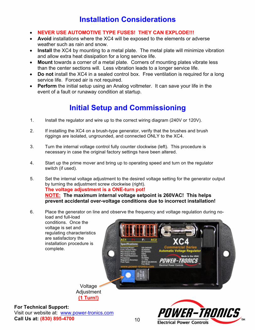
6. Place the generator on line and observe the frequency and voltage regulation during no-
load and full-load conditions. Once the voltage is set and regulating characteristics are satisfactory the installation procedure is complete.
Voltage
Adjustment (1 Turn!)
11
For Technical Support: Visit our website at: www.power-tronics.com Call Us at: (830) 895-4700
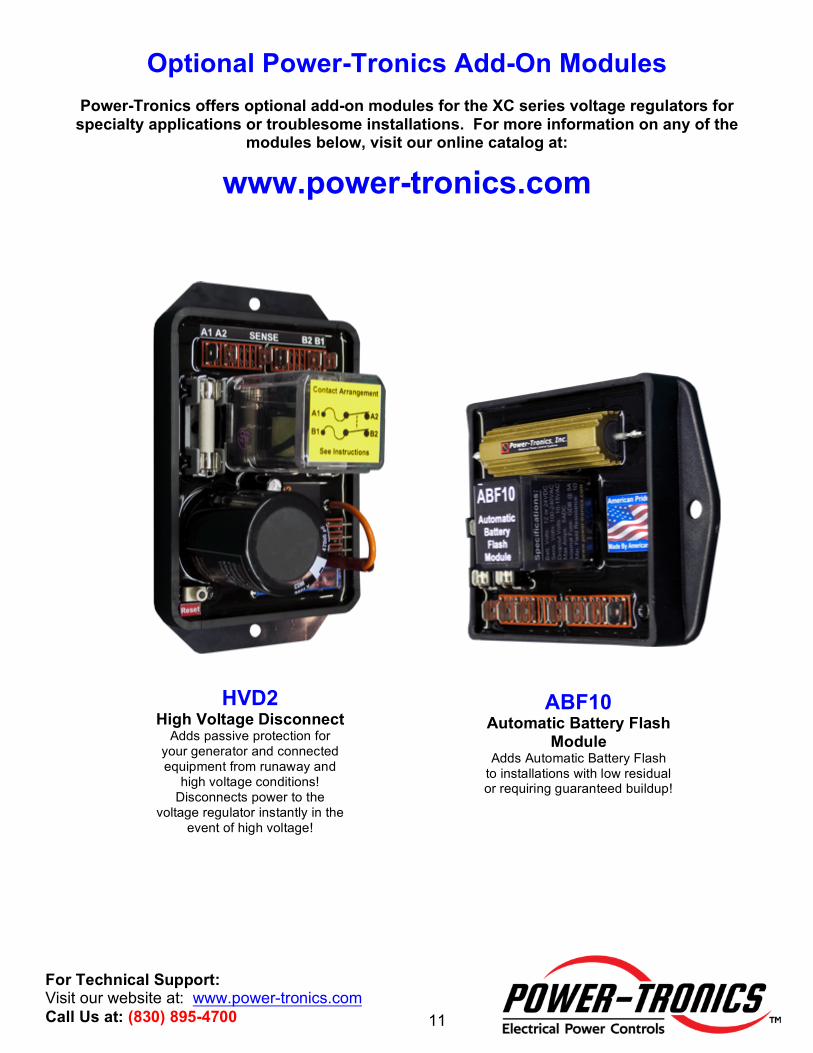
Optional Power-Tronics Add-On Modules
Power-Tronics offers optional add-on modules for the XC series voltage regulators for specialty applications or troublesome installations. For more information on any of the
modules below, visit our online catalog at:
www.power-tronics.com
ABF10 Automatic Battery Flash
Module Adds Automatic Battery Flash
to installations with low residual or requiring guaranteed buildup!
HVD2 High Voltage Disconnect
Adds passive protection for your generator and connected equipment from runaway and
high voltage conditions! Disconnects power to the
voltage regulator instantly in the event of high voltage!
12
For Technical Support: Visit our website at: www.power-tronics.com Call Us at: (830) 895-4700
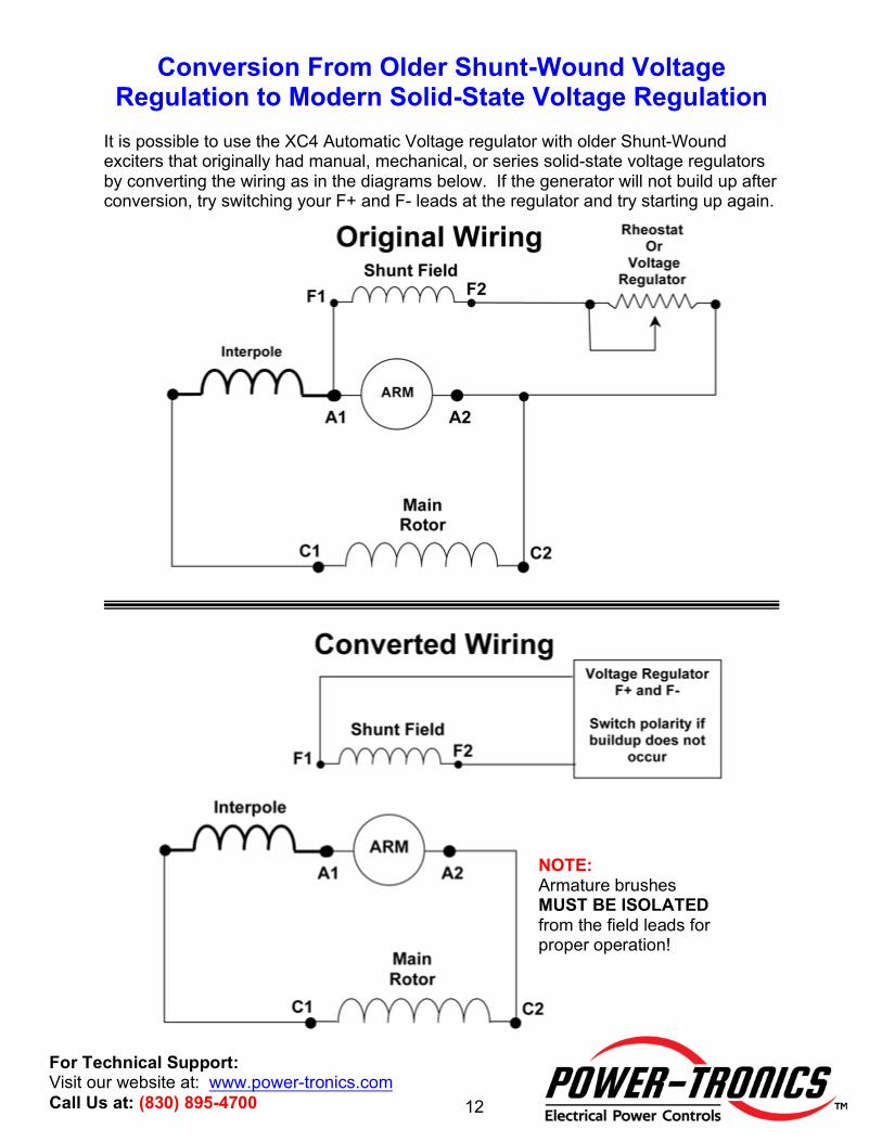
Conversion From Older Shunt-Wound Voltage Regulation to Modern Solid-State Voltage Regulation
It is possible to use the XC4 Automatic Voltage regulator with older Shunt-Wound exciters that originally had manual, mechanical, or series solid-state voltage regulators by converting the wiring as in the diagrams below. If the generator will not build up after conversion, try switching your F+ and F- leads at the regulator and try starting up again.
NOTE: Armature brushes MUST BE ISOLATED from the field leads for proper operation!
13
For Technical Support: Visit our website at: www.power-tronics.com Call Us at: (830) 895-4700
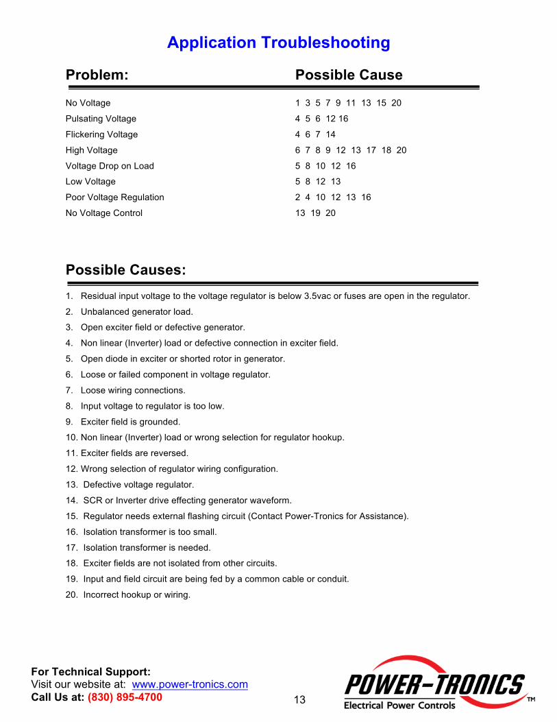
Application Troubleshooting Problem: Possible Cause No Voltage 1 3 5 7 9 11 13 15 20
Pulsating Voltage 4 5 6 12 16
Flickering Voltage 4 6 7 14
High Voltage 6 7 8 9 12 13 17 18 20
Voltage Drop on Load 5 8 10 12 16
Low Voltage 5 8 12 13
Poor Voltage Regulation 2 4 10 12 13 16
No Voltage Control 13 19 20
Possible Causes: 1. Residual input voltage to the voltage regulator is below 3.5vac or fuses are open in the regulator.
2. Unbalanced generator load.
3. Open exciter field or defective generator.
4. Non linear (Inverter) load or defective connection in exciter field.
5. Open diode in exciter or shorted rotor in generator.
6. Loose or failed component in voltage regulator.
7. Loose wiring connections.
8. Input voltage to regulator is too low.
9. Exciter field is grounded.
10. Non linear (Inverter) load or wrong selection for regulator hookup.
11. Exciter fields are reversed.
12. Wrong selection of regulator wiring configuration.
13. Defective voltage regulator.
14. SCR or Inverter drive effecting generator waveform.
15. Regulator needs external flashing circuit (Contact Power-Tronics for Assistance).
16. Isolation transformer is too small.
17. Isolation transformer is needed.
18. Exciter fields are not isolated from other circuits.
19. Input and field circuit are being fed by a common cable or conduit.
20. Incorrect hookup or wiring.
14
For Technical Support: Visit our website at: www.power-tronics.com Call Us at: (830) 895-4700
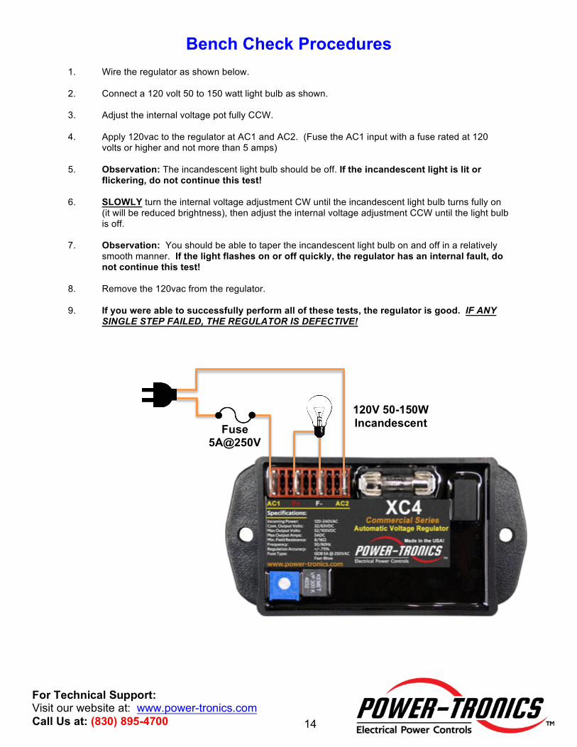
Bench Check Procedures 1. Wire the regulator as shown below. 2. Connect a 120 volt 50 to 150 watt light bulb as shown. 3. Adjust the internal voltage pot fully CCW. 4. Apply 120vac to the regulator at AC1 and AC2. (Fuse the AC1 input with a fuse rated at 120
volts or higher and not more than 5 amps) 5. Observation: The incandescent light bulb should be off. If the incandescent light is lit or
flickering, do not continue this test! 6. SLOWLY turn the internal voltage adjustment CW until the incandescent light bulb turns fully on
(it will be reduced brightness), then adjust the internal voltage adjustment CCW until the light bulb is off.
7. Observation: You should be able to taper the incandescent light bulb on and off in a relatively
smooth manner. If the light flashes on or off quickly, the regulator has an internal fault, do not continue this test!
8. Remove the 120vac from the regulator. 9. If you were able to successfully perform all of these tests, the regulator is good. IF ANY
SINGLE STEP FAILED, THE REGULATOR IS DEFECTIVE!
120V 50-150W Incandescent Fuse
5A@250V
15
For Technical Support: Visit our website at: www.power-tronics.com Call Us at: (830) 895-4700
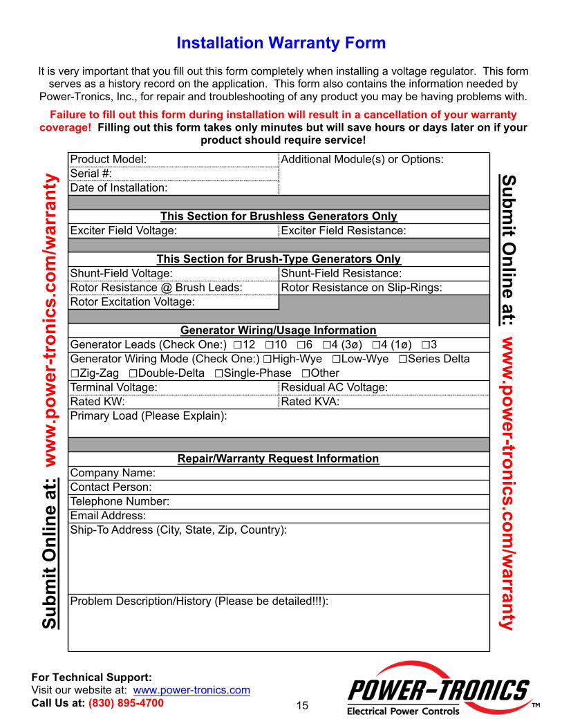
Installation Warranty Form It is very important that you fill out this form completely when installing a voltage regulator. This form
serves as a history record on the application. This form also contains the information needed by Power-Tronics, Inc., for repair and troubleshooting of any product you may be having problems with.
Failure to fill out this form during installation will result in a cancellation of your warranty coverage! Filling out this form takes only minutes but will save hours or days later on if your
product should require service!
Problem Description/History (Please be detailed!!!):
Ship-To Address (City, State, Zip, Country):
Company Name:Contact Person:Telephone Number:Email Address:
Primary Load (Please Explain):
Repair/Warranty Request Information
Generator Leads (Check One:) 12 10 6 4 (3ø) 4 (1ø) 3Generator Wiring Mode (Check One:) High-Wye Low-Wye Series Delta Zig-Zag Double-Delta Single-Phase OtherTerminal Voltage: Residual AC Voltage:Rated KW: Rated KVA:
Generator Wiring/Usage Information
This Section for Brushless Generators OnlyExciter Field Voltage: Exciter Field Resistance:
This Section for Brush-Type Generators OnlyShunt-Field Voltage: Shunt-Field Resistance:Rotor Resistance @ Brush Leads: Rotor Resistance on Slip-Rings:Rotor Excitation Voltage:
Product Model:Serial #:Date of Installation:
Additional Module(s) or Options: Submit O
nline at: ww
w.pow
er-tronics.com/w
arranty Subm
it O
nlin
e at
: w
ww
.pow
er-tr
onic
s.co
m/w
arra
nty
16
For Technical Support: Visit our website at: www.power-tronics.com Call Us at: (830) 895-4700
PRODUCT WARRANTY Power-Tronics, Inc., assumes no liability for damages due to incorrect voltage or other voltage
related damages resulting from either output of the generator or input to the generator exciter
system. These problems should be protected with external devices provided by the customer
such as fuses, surge suppressors, over/under voltage and frequency controls.
Power-Tronics, Inc., warranties only parts and workmanship of this product for a period of 1 year from the original date of purchase from Power-Tronics, Inc. Under warranty, Power-
Tronics, Inc. will replace, exchange or repair the defective product without labor or parts cost to the customer. Remaining warranty of the original product will be transferred to the replaced
or repaired product. To obtain warranty, a copy of the original Installation Warranty Form must
be sent in with the defective product, which clearly shows the purchase date and serial number
of the defective part. A repair request form must be sent in with the product before repairs will
begin. You can obtain this form by contacting Power-Tronics, Inc.
Send repairs to: Power-Tronics, Inc., 2802 Cobbler Ln., Kerrville Texas USA 78028.
Send in repairs only by UPS or FedEx. USPS will NOT deliver to our facility!
Any one of the following conditions will void the warranty:
v Overheating of the power supply resistor(s) on the printed circuit card.
v Overheating of the SCR or freewheeling diode.
v Physical damage to the printed circuit card, housing or components.
v Unauthorized repair or alteration of printed circuit card.
v Installation by anyone other than a qualified professional generator service technician.
v Conductive or corrosive contamination of the circuit card.
v Removal of our company identification from the product. v Removal of any conformal coating of the printed circuit card or components.
v Overheating of encapsulant, or explosion of components encased within. v Inappropriate or infeasible installation or application. v Use with any external device other than manufactured by Power-Tronics, Inc. v Failure to adequately fuse the incoming power to the voltage regulator.
v Failure to fill out the attached warranty card during installation
No other warranty is expressed or implied.