Embed Size (px)
Citation preview
Commissioning of CIL’s Ammonia II Plant
W. K. Taylor CIL Inc., Courtright, Ontario, Canada
A. Pinto Imperial Chemical Industries PLC, Billingham, England
Special features of this process design contributed to fast start-up, including the role of the computer simulator for training purposes and
the concept of commissioning b y process test system.
INTRODUCTION
The CIL Ammonia I1 plant came on-stream successfully in August, 1985. The plant is based on ICl’s AMV tech- nology and is located at CIL Inc., Lambton Works, near Sai-nia, Ontario, Canada. Design capacity is 1120 tonnes per day, at a total energy requirement of 29 GJ (LWV)/ metric ton.
First ammonia prod tic ti on was ac h i evetl 1 e s s t hair two days after feed gas introduction, which we consider to be a world-record. Furthermore, the total amomit of natural gas used for all commissioning activities amounted to only 3.0 days supply at design rate. These achievements were made possible b y the use of import syii gas to re- duce catalysts and to commission equipment. Design pro- duction rates have since been achieved arid inaintained.
Project Development
The CIL Airiinoiiia I1 plant represents the first commer- cial application of the ICI AMV proce merit was by CIL Engineering Dept., Toronto, while commissioning and siibsequent prodnction were respon- sibilities of the Works. The process package was devel- oped by ICI, Billingham, U.K., along with the team of CIL engineers.
Detailed engineering and procurement was by Uhde, Dortmund, West Germany. Uhde handled mechanical and process design and retained SNCIFW, Montreal, Canada to do the civil, electrical and iiistrunientation de- sign. Equipment procurement was done on a worldwide hasis. Construction was managed hy Bechtel Canada Ltd.
The above demonstrates the true internatiorial team ef- fort that was involved in this project. In fact, special satel- lite communications networks were set up between major design offices and the construction site, in order to facili- tate communications across the wide distances and sev- eral time zones.
PROCESS DESCRIPTION
The ICI AMV process design features low energy con- sumption without increasing capital cost. Plant relia1)ility is enhanced as an inherent outcome of the process de- sign, arid also because proven technology is used for most of the process steps.
106 April, 1987
T h e ICI AMV process as applied for the CIR site wits optimized for specific economic conditions exi\ting at the site. These are the relatively high cost of ii;,ttural gas feedstock compared to the relatively low cost ai id reliable supply of electrical power. This lead to the conrept of the all electric drive plant. With a more energy efficient pro- cess design, the steam generation is considerably re- duced. Hence, oiily one large efficient steam ttirbiiie is used, driving the process air compressor anti an alter- nator. Excess shaft power, over that required for the pro- cess air compressor, is converted to electrical power in the alternator, thus reducing import power needs. The alternator is synchronized to the Ontario pow*er grid, thus making this train a fixed speed machine. This design coii- cept has several advantages:
It reduces capital cost as remaining drive:; are elec- tric motors, which are cheaper. I t improves operaliility and flexibility of operation, since the electric drives can be operated indepeir- dent of the steam system. Operability is improved since upsets in the steam system are reflected in either inore or ltbss power generated by the alternator, and hence more or less power imported to the plant, rather than in changes through the whole process.
The process air compressor is innovative in f hat inter- stage cooling has been minimized such that the (discharge temperatiire is 400°C (750°F). The effect is that the pro- cess air can be fed directly to the secondary r t h x i e r at
pre- heat coil. While requiring more power to operate such a compressor, the incremental power cost of doiiig so is at the cost of electrical power import and is justified by the overall plant economics.
All other compressor, pump and fan drives are electric
The process design features include:
this temperature, thus eliminating the need for ;in ‘llr .
motors.
ICI process design and Uhde niechanical design for the primary reformer, fea turi r i g 111 i I d e r re forming conditions and a shift towards m o r e secoudary re- forming. Feed gas saturator in the front-end of the I)laiit pro- viding about half the process steam, while at the same time, virtually eliminating the process con- densate stream for disposal.
Plant/Operotions Progress (Vol. 6, No. 2)
30 M W double- extract i onicon den s in g steam tur- bine driving the alternator and process air com- pressor. Steam extraction at 40 bar (565 psig) for process me and at 16 liar (220 psig) for plant export. Process air compressor with discharge conditions at 38 bar (535 psig) and 400°C (750°F). Selexol low energy CO,-reinoval system. Electrically driven single casing syn gas com- pressor with discharge at 85 Imr (1220 psig). For start-up conditions this machine is designed to op- erate at 50% speed on a nitrogen heat-up circuit through the front-end of the plant. A part ofthis cir- cuit is also used for the LTS rediiction. Separate ammonia circulator which boosts the syn gas by about 5 I~a r and circulates it around the syn l00p. Low pressnre syn loop featuring ICI low pressure ammonia synthesis catalyst. Cryogenic hydrogen recovery unit to remove inerts and excess nitrogen from the syn loop purge gas. Kecovered hydrogen is recycled to the circulator suction. Distributed digital control system, with CIL-devel- oped “Cygnus” supervisory computer and a fully redundant live mare commterized trio svstrm.
I ,
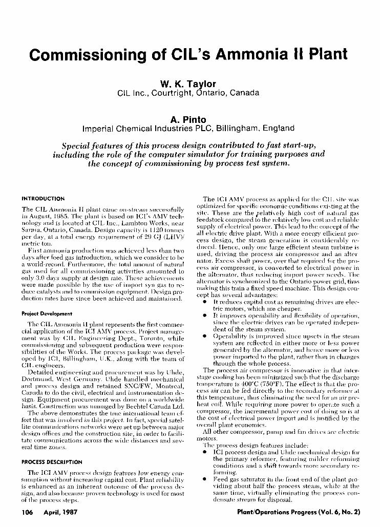
See Figure 1 for a simplified flowsheet. Further de- scription of the AMV process is given in Reference 1.
OPERABILITY & HAZARD REVIEWS
A design technique used by the worldwide ICI family of companies in the development of process designs and P&I drawings is the Operability and Hazard (O&H) study. This technique was used by the team of CIL and ICI engineers to conduct a rigorous examination of the plant on a line by line basis to consider all upset condi- tions.
Typical conditions considered are: 0 high temperature
low temperature 0 reverse flow
high pressure low pressure change in composition
These O&H studies were conducted in several phases, from initial concept right through to commissioning.
Two examples will illustrate the value of O&H re- views. A bypass w a s installed around a set of gas driers to improve operahility in the event of a drier failure. In an- other area, special slam shut valves were added to limit the size of relief valves. Comprehensive O&H studies were a key element in providing a safe arid operable design.
clrNl.ryr w r e r u r
Figure 1. Simplified AMV flowsheet.
Plant/Operations Progress (Vol. 6, No. 2)
STEAMIPOWER STUDIES
The steam/power system is the heart of all ammonia plants and a stable system is the key to a siiccessfiil de- sign. ICI has the facility to perform dynamic computer simultations of process plants to study both normal and upset conditions. This fk i l i t y was used by CIL to con- duct a steamipower stability study. Although our steam system is downsized compared to conventional designs, and relatively simple in concept, the controls around the main steam turbine are complex. This aspect of the de- sign was studied in detail and as a result, some modifi- cations were made to the controls.
COMMISSIONING STRATEGY
Our goal was to bring the plant on-line as soon a s possi- ble after construction activities were completed, and, in a safe and efficient manner. Our production target was arn- bitious for the remainder of the year, yet our commis- sioning budget was very modest. How were we to meet our objectives?
A commissioning strategy was developed that opti- mized on the design features of the AMV process by fo- cusing on a) comm ioning by process test systems, 11) the use of import syn gas, and c) training.
The AMV process design lends itself to a very efficient and flexible commissioning phase. The use of electric motor drives for all drives except the process air com- pressor, and the use of a separate circulator on the syn loop, enabled us to plan for the testing of each plant area without having to start-up the whole plant or to commis- sion the steam system. In other words, the AMV process fit in very well with the concept of commissioning by pro- cess test system.
We also took advantage of the fact that our existing Am- monia I unit was adjacent to the new plant - we could obtain syii gas from Ammonia I, or even a stream of 90% hydrogen from the cold box recovery unit. From the earliest design stages we planned to use import syn gas from Ammonia I in order to conduct Ammonia I1 commis- sioning activities while the plant was off-line.
Training of our operating crews was also a crucial ele- ment in the overall strategy and a lot of resources were devoted to this function.
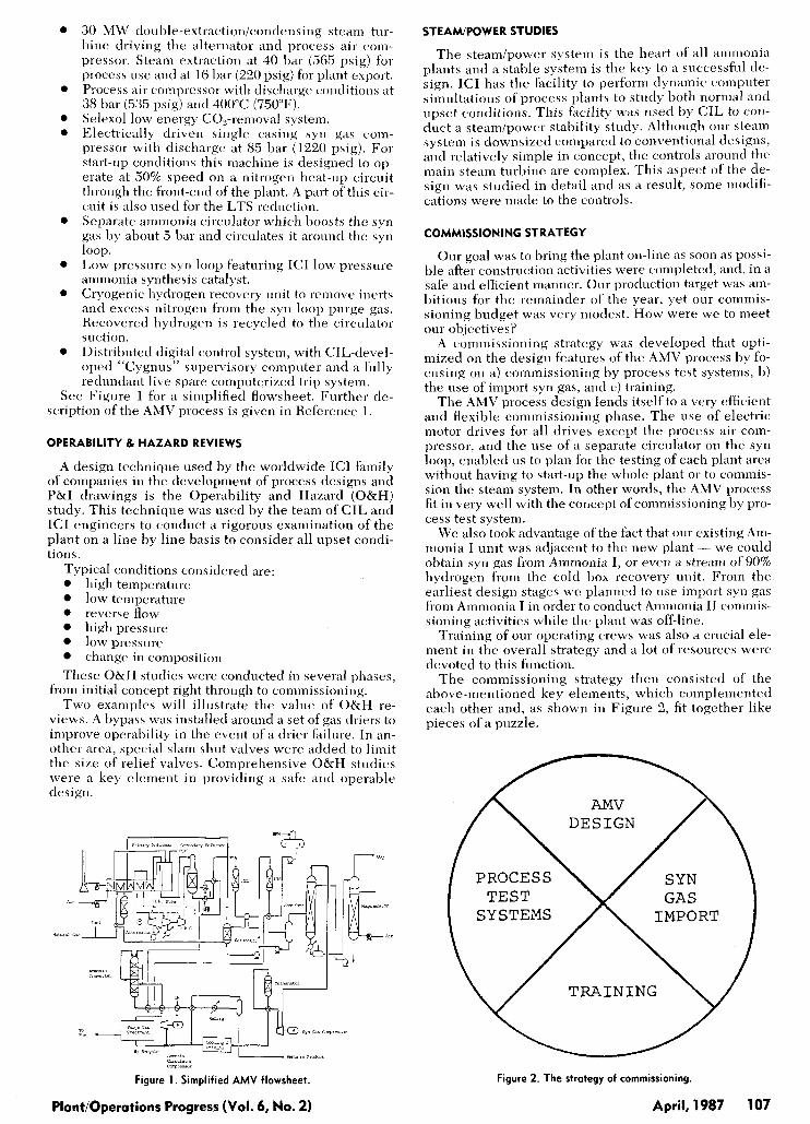
The commissioning strategy then consisted of the above-mentioned key elements, which complemented each other and, as shown in Figure 2, fit together like pieces of a puzzle.
/-
T R A I N I N G
Figure 2. The strategy of commissioning.
April, 1987 107
First, a team had to be put in place to implement strat- egy. I t should be emphasized that we had an integrated CIL project team with commissioning/production repre- sentation from the earliest days of the project. Hence the key parts of the commissioning strategy were planned for at the design stages.
The Comniissioning Team consisted of Processicom- missioning engineers recruited from the Works, from other locations in CIL, and, from ICI, and some ICI affiliated companies; Engineering specialists in various disciplines (electrical engineer, project engineer, plan- ner, rotating equipment specialist, etc.) and support staff; a process control group including specialists in computer generated graphics, digital controls, trip computers, etc.; senior process consultants from ICI and Uhde, plus oper- ators and foremen recruited from the Works and experi- enced in the Ammonia I plant.
As required, the team was supplemented with various vendor representatives, as the many equipment items came to be commissioned. At its peak, the commissioning team numbered about 60 people.
COMMISSIONING BY PROCESS TEST SYSTEMS
In order to minimize the commissioning period it was decided very early in the project to commission by test systems. This meant, also, that the construction group had to finish the plant by test system.
Early in the design stage, the commissioning team di- vided the plant, including off-sites, into al)out 140 process test systems (PTS’s). A PTS was defined as a section of plant, upon which commissioning activities could lie per- formed more or less independently; for example, a pump circuit complete with electrics and instrunients which could be tested on water, or a steam main which could he blown or chemically cleaned. In turn, these PTS’s were grouped into 12 “megasystems” for the battery limit am- monia plant, for example the entire water treatment plant, or the entire syn loop.
Besides defining the PTS’s, the commissioning team also developed the optimum schedule or order in which we wished to accept these systems from construction. The construction group worked diligently to complete systems on schedule and i n the order requested.
Since each project uses somewhat different terminol- ogy, the following summarizes our definitions: Process Test System (PTS): A section of plant which could be tested or commissioned independent of other systems. PTS Handover: Transfer of responsibility from the Con- struction Team to the Commissioning Team. All hand- over procedures were subject to exceptions, punch lists, deficiency lists, etc. Megasystem: A group of PTS’s which could he operated together for commissioning, after precommissioning ac- tivities were complete. For example, Megasystem #8 was the ammonia circulator arid the entire syn loop. With all PTS’s in this megasystem, we could circulate import syn gas around the loop, do a full load test on 5-401, trip tests, vibration tests, etc., conduct a load test on the start-up heater, and eventually d o the converter catalyst reduc- tion. __--___ Area Handover: Transfer of responsibility of a geographic area from Construction to Commissioning. The concept of area handover was used to prevent introduction of haz- ardous chemicals (ammonia say) in a PTS adjacent to areas where many construction activities were still occur- ring. Pre-Cominissioning: Those activities pertaining to the checking, testing, cleaning, dry-out, etc., of test systems. Mechanical Completion: Occurs when the section of the plant is complete per the specs and drawing. Precom-
missioning is complete to the extent that comriiissioning can begin. Commissioning: At this stage process cheniicals and gases are introduced and heating, cooling, pre5surization etc., occur.
By following the commission by test system str. t egy, we were, in effect, starting and testing plant equipment as soon as Construction was finished with it. This required the utmost co-operation and communication between groups in order to do the job safely and efficiently, espe- cially when there were several exceptions or punch list or deficiency list items outstanding. The Works hlainte- nance Team were also involved in this interfice. niain- taining equipment after handover and performing essen- tial modifications as required.
USE OF IMPORT SYN GAS
A syn gas tie-line was installed between oiir existing Ammonia I unit and the new Ammonia 11. Basically, two types of syn gas could be provided, namely:
a) syn gas from the interstage of the compressor, at 61 bar (870 psig) and 3/1 H,/N, ratio, and,
11) cold box product at 61 bar pressure and ‘30% hydro- gen, 8% nitrogen.
Provision of the iniport syn gas enaliled us t o perform several essential commissioning activities off-line. These were: ~______. LTS Reduction: Since the plant design provided for nitro- gen circulation in the front-end (for heat-up, cool down, etc.) using the syn gas compressor, it was an e,isy matter to use the import hydrogen for the LTS reduction step. Commissionin2 of Ammonia Circulator: The circulator compressor on the syn loop is designed only to operate on syn gas -testing with air or nitrogen was not possible. By using import syn gas, however, this compressor could be tested under design conditions. Ammonia C h v e r t e r Reduction: This was, of c.i)urse, the longest and potentially most costly coniniissioiiing step. Using import syn gas, however, in combinatioii with the separate and motor-driven circulator, would allow us to do this activity without having to operate the front-end of the plant. For this step, the 90% hydrogen stream was to be used because of the unique advantages it offered. Use of this stream for the reduction would result in very little ammonia production and no exothermic heat of reaction to complicate the reduction procedure. Hence the reduc- tion could be easily controlled. Also, there would lie very little aqua ammonia produced to dispose of, h ) u t 120 tonnes of 20% aqua ammonia - an easily mmageable quantity. Testing of Syn Gas Compressor: Use of import syn gas would allow the testing of this machinc under design conditions.
In summary, the use of import syn gas was reckoned to save us millions of dollars in start-up gas and at least sev- eral weeks of time in bringing the plant oil-strtwii.
TRAINING
Training was one of the key elements of the strategy and the one with the most long-term effects. Operating personnel were all selected from the existing Works. Most were experienced in our Ammonia I unit and those who had only limited experience in Ammonia I were ex- perienced in other plants.
A vital part of the training program was (and \till is) the process simulator. This is a dynamic computer simulation of the process that provides a real-time hands-on training experience. This simulator was provided by Combustion Engineering Simcon aiid proved invaluable i n training operating personnel in: the use of unfamiliar digital con- trol systems, the performance of the new process including start-up, shut-down, steady-state, wnd emer-
Plant/Operations Progress (Vol. 6, No. 2) 108 April, 1987
gency response to dozens of pre-programmed instructor initiated upsets or process trips.
The simulator provided was a very sophisticated fully integrated model of the whole process plant and included steady-state, start-up, shutdown and all trip and upset conditions [ 2 ] .
The training program consisted of three phases, namely classroom, simulator, and, on-the-job training. All operat- ing personnel received classroom training. This began 12 months before the plant started up and this early start was required in order that we could put trained men in the field some 8 months prior to scheduled mechanical coin- pletion.
The simulator was available in November 1984, and was used to train the twelve operators who were to be the control room and compressor operators. These men re- ceived about 100 hours each on the simulator. Various formal exercises were carried out on the simulator. Since the simulator could handle only 3 men at a time, person- nel were recycled between field duties (on-the-job train- ing) and the simulator. In January 1985, shift coverage be- gan and the simulator was available on a 24 houi-/day basis. This arrangement worked very well and lulls in field activities were filled in with simulator training. Sub- sequent plant experience and performance have deinon- strated the value of simulator training.
The remainder of the operating crews received class- room and on-the-job training for periods ranging from five to eight months prior to start-up.
THE COMMISSIONING EXPERIENCE
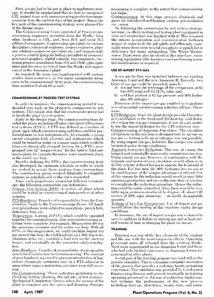
Figure 3 shows a summary of the key handover dates for the battery limit megasystems. This is really an over- simplified view of the situation as each megasystem con- sisted of between 3 and 20 PTS's and the handover dates indicate completion of a l l pre-commissioning activities. Inevitably there were some delays and some advances in handover dates. The systems were handed-over basically in the sequence requested and commissioning activities were carried out on some systems as constrnction of otli- ers was being completed.
Inevitably, in spite of all the planning, any coinmis- sioning period will be faced with many problems to solve. The following is a sample of the several problems we faced.
During water flushing of the Selexol system, heat input from the pumps caused the water to rapidly pick up heat. With no provision for cooling we con- nected fire hoses to make-up cold water while blow- ing down hot water, thus enabling the system to run at 50-60°C (120-140°F). On commissioning of the refrig compressor on am- monia duty, we could not get enough flow through
Figure 3. Handover dates.
PlcdOperations Progress (Vol. 6, No. 2)
the kick-back valves. To solve the problem, the in- line silencers were removed, and larger holes were drilled in the silencer cages of the control valve trims. During commissioning of the steam system, prob- lems were encountered with the automatic recircu- lation valves on the boiler pumps, wiring on the package boiler, supports on the boiler relief valve, and problems with level control valves on the boiler, requiring piping modifications. Piping and structural steel modifications were re- quired around the Selexol pumpihydraulic turbine because of pump vibration plus structural consid- erations. Lube oil flushes fortunately were started several months before mechanical completion. Some sys- tems were slow to clean to a final level of accept- ance and chemical cleaninglflushing was resorted to in some cases. After the ammonia circulator com- pressor, J-401, lube oil system was slow to clean up, the seal oil tank was examined and dirt was ob- served to be caught behind a standpipe. This was removed physically and the oil system then promptly met cleanliness specs. Leaking vent valves and block valves caused prob- lems on several systems.
All these problems were dealt with promptly and with the utmost cooperation between the various groups involved.
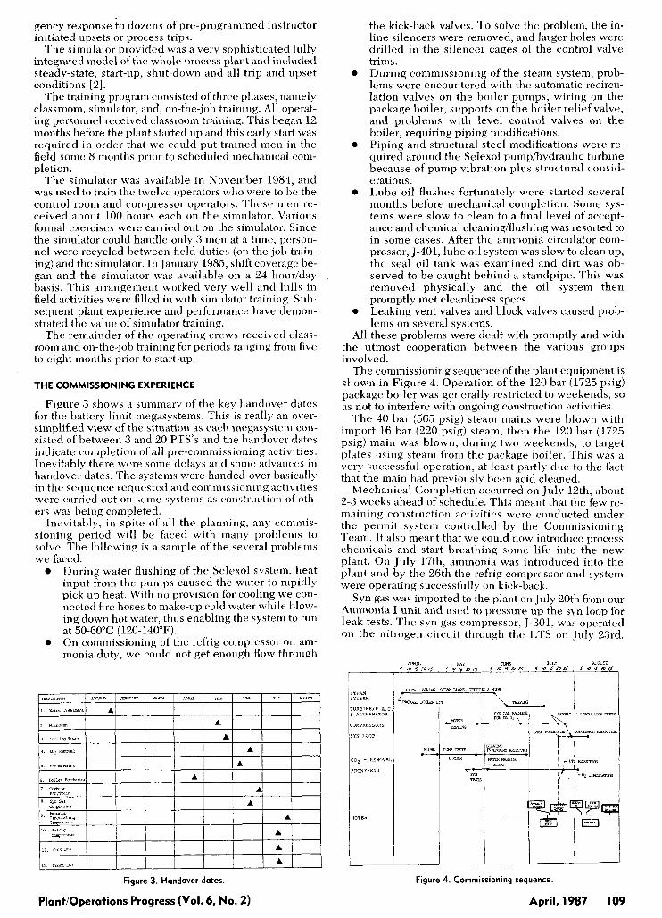
The commissioning sequence of the plant equipment is shown in Figure 4. Operation of the 120 bar (1725 psig) package boiler was generally restricted to weekends, so as not to interfere with ongoing construction activities.
The 40 har (565 psig) steam mains were blown with import 16 bar (220 psig) steam, then the 120 bar (1725 psig) main was blown, during two weekends, to target plates using steam from the package boiler. This was a very successful operation, at least partly due to the fact that the main had previously been acid cleaned.
Mechanical Completion occurred on July 12th, about 2-3 weeks ahead of schedule. This meant that the few re- maining construction activities were conducted under the permit system controlled by the Commissioning Team. It also meant that we could now introduce process chemicals and start breathing some life into the new plant. On July 17th, ammonia was introduced into the plant and by the 26th the refrig compressor and system were operating successfully on kick-back.
Syn gas was imported to the plant on J U ~ Y 20th from our Ammonia I unit and used to pressure up the syn loop for leak tests. The syn gas compressor, 5-301, was operated on the nitrogen circuit through the LTS on Jiily 23rd.
SYSTEM
TURBINE/P.R.C L iiLTERNRTOR
COMPRESSORS
SYN LOOP
co2 - REMOViiL
FRONT-END
NOTES
Figure 4. Commissioning sequence.
April, 1987 109
Import syn gas was introduced to the circuit and the LTS reduction was completed successfully with no interrup- tions in less than 24 hours.
By J d p 28th, the refrig system was ready, and the ain- monia circulator 5-401 was circulating 90% hydrogen around the syn loop. The start-up heater was lit and grad- ually hrought up to temperature to effect the dry-out, a procedure that took less than a day with ceramic fibre re- fractory walls. The reduction reaction Iiegan immediately and the first load of aqua ammonia was removed on July 29th. We then experienced a flange leak which required a 2.5 day interruption to the reduction in order to re-align piping. Upon re-starting, the reduction proceeded smoothly and was complete by August 6th. Total time taken was Y days including the 2.5 day interruption.
As expected, the reduction reaction proceeded in an easy to control manner without the exothermic heat of re- action to contend with and aqua ammonia production was also minimized. Almiit 25 tonnes of aqua was disposed of. We then made some temporary connections and pro- cessed the reinainirrg 90-100 tonnes of aqua ammonia through the ammonia still, which is part of the purge gas recovery system.
During all the key commissioning steps requiring the use of import syn gas, our Amniouia I unit provided the syn gas when required. Literally millions of dollars were saved by capitalizing on the availability of syn gas and the AMV technology that could take advantage of it during the commissioning phase.
THE INITIAL START-UP
With the L.T.S. and ammonia converter catalysts re- duced, the plant was essentially ready for start-up. The final commissioning activity was the in-situ hlowing and calibrating of the 120 bar (1725 psig) steam relief valves.
In anticipation of the completion of the converter re- duction, steam w a s introduced to the primary reformer on the evening of August 4th. The Selexol system was oper- ated with nitrogen pressure on the absorber, but we could not maintain sufficient pressure with the one inch nitro- gen supply line provided. We decided we would have to wait for feed gas introduction to get sufficiently high ab- sorber pressure to operate the system properly. Duriilg this period, August 6-7, some delays were experienced due to minor mechanical and electrical problems. The L.T.S. was preheated using nitrogen circulation. The main steam turbine, JT-101, was slow rolling. At 9:OO p.m. on August 7th, feed gas was introduced to the pri- mary reformer for the first time. At midnight, however, a level transmitter fhiled on the deaerator, indicating a f:dse high level and thus cutting the make up flow. When the low level alarnr came in, the error was realized but it was too late. We lost suction to the boiler pumps. The re- former tripped and all compressors had to be shutdown. By 5:OO a.m. natural gas feed was back in the plant.
Problems controlling condensate levels in the front- end of the plant at low rates were largely overcome by raising the gas rate and the pressure. Some minor delays were experienced due to instrumentation problems. The main turbine JT-101 was started and slow-rolled in prepa- ration for process air introduction, and at 2:OO p.m. the refrig machine was started and operated on kick-back.
At 5:OO p.m., process air was introduced at 10% rate. The air rate was gradually increased and the plant pres- sure increased in order to increase the absorber pressure. At 8:OO p.m., the antmonia circulator was started and the converter was slowly brought up to reaction temperature (again, using imported syn gas).
The L.T.S. as swung on-line at 10:OO p.m. By 340 a.m., August Yth, the Selexol system was in service with all the process gas through the system. It was intended to start the syn gas compressor, but a fault in the electrics de-
1 10 April, 1987
layed this until the day shift. At 9:ZO am. , August Yth, the J-101 turbine w;is synchro-
nized to the Ontario power grid (a relatively complex step that we subsequently accomplish before process air intro- duction.) The machine was now geiierating power, through the alternator, and with a fixed speed. any upsets in our steam system would be reflected in the import versus generated power I -dance and would not cascade through the plant.
The syn gas compressor was started and operated on kickback a s the methanator was heated to re;tctioii tem- perature (methanator is on the discharge sides of the syn gas compressor).
By 3:45 p.m. the compressor was overlieatiirg from lie- ing operated on kick-back at low flow for severiil hours. As everything was now ready, we brought the g ~ s forward and directly into the syn loop. Since the syii loop w a s circulating at reaction temperature, ammonia production started immediately. Production began at 4:OO p.m., only 43 hours from feed gas introduction, a real achievement considering the plant trip and the several mi nor delays that occurred in this period. The next several hours were quite busy and frantic. Ammonia product was being ex- ported for the first time and was being loaded directly into tank cars. The initial surge of process gas through the syn gas compressor had the effect of reducing the ab- sorber pressure. Corrective action had to be taken with the Selexol system to control a CO, lweakthrough and limit the temperature excursion in the methanator. By 6:OO p.m. the unit was relatively steady at 100% front-end rate and about 50% production rate.
The initial production was all usable. The fil.jt two tank cars of ammonia contained 3-4% water and t liese wjere used internally on our site by consuming p1ant:i. The next two tank cars were only slightly off-spec. No product iiiii-
nionia had to be disposed of. Before our new plant had much of a chance to settle
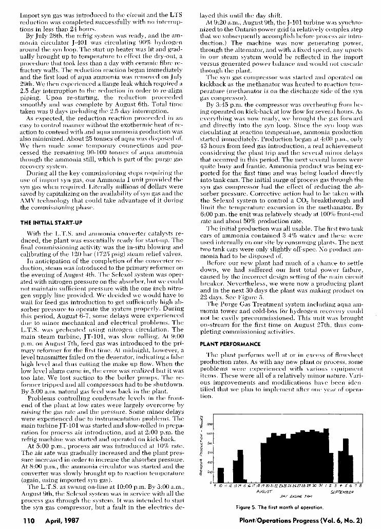
down, we had suffered our first total power failure, caused by the incorrect design setting of' the main circuit breaker. Nevertheless, we were now a prodirciiig plant and in the next 30 days the plant was making product on 22 days. See Figure 5.
The Purge Gas Treatment system including aqiia ain- monia tower and cold-box for hydrogen recovery could not be easily precommissioned. This unit wits brought on-stream for the first time on August 27th, thus com- pleting commissioning activities.
PLANT PERFORMANCE
The plant performs well at or in excess of' flowshcet production rates. As with any new plant or process, some problems were experienced with various cquiprrrent items. These were all of a relatively minor nature. Vari- ous improvements and modifications have I)eerr idrn- tified that we plan to implement after one year of opera- tion.
hUGU5T SPrEMBER D n Y LNZVN6 7Lln
Figure 5. The first month of operation.
PlantIOperations Progress (Vol. 6, No. 2)
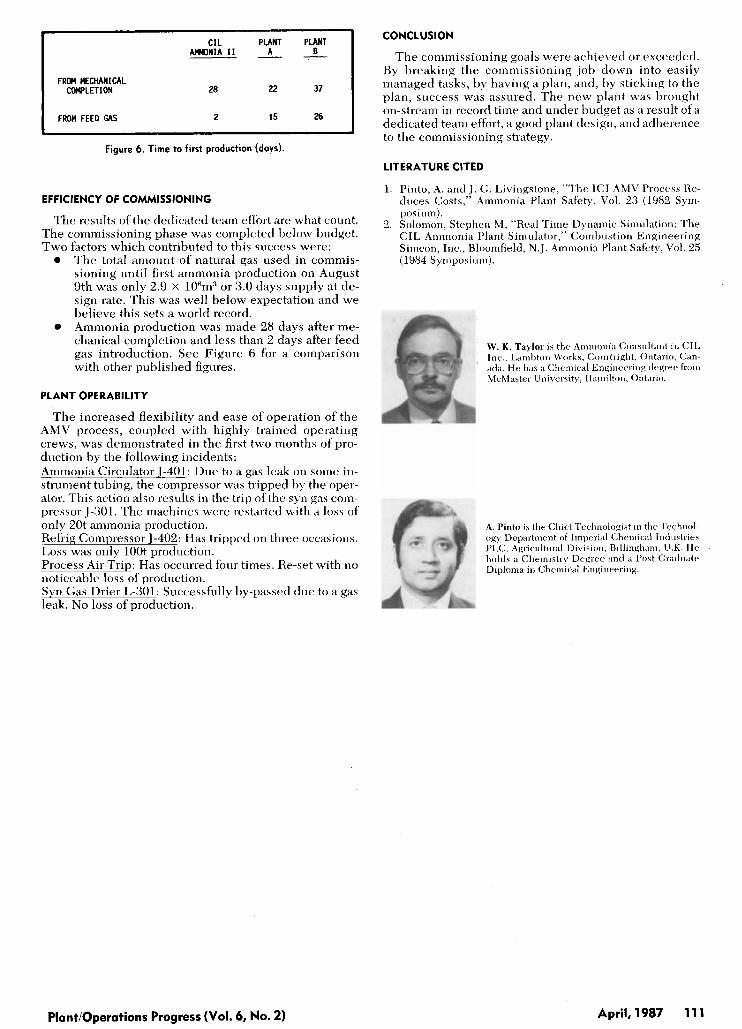
C I L PLANT PLANT AmONIA I 1 A 8 - - -
FROM MECHANICAL COWLETION 2a 22 37
FROU FEED GAS 2 15 26
Figure 6. Time to first production (days).
EFFICIENCY OF COMMISSIONING
The results of the dedicated team effort are what count. The commissioning phase was completed below budget. Two factors which contributed to this success were:
The total amount of natural gas used in commis- sioning until first ammonia production on August 9th was only 2.9 x 10”m3 or 3.0 days supply at de- sign rate. This was well below expectation and we believe this sets a world record. Ammonia production was made 28 days after me- chanical completion and less than 2 days after feed gas introduction. See Figure 6 for a comparison with other published figures.
0
0
PLANT OPERABILITY
The increased flexibility and ease of operation of the AMV process, coupled with highly trained operating crews, was demonstrated in the first two months ofpro- duction by the following incidents: Ammonia Circulator J-404: Due to a gas leak on some in- strument tubing, the compressor was tripped by the oper- ator. This action also results in the trip ofthe syn gas com- pressor 5-301. The machines were restarted with a loss of only 20t ammonia production. Refrig Compressor 5-402: Has tripped on three occasions. Loss was only lO0t production. Process Air Trip: Has occurred four times. Re-set with no noticeable loss of production. Syn Gas Drier L-301: Successfully by-passed due to a gas leak. No loss of production.
CONCLUSION
The commissioning goals were achieved or exceeded. By breaking the commissioning job down into easily managed tasks, b y having a plan, and, by sticking to the plan, success was assured. The new plant was brought on-stream in record time and under budget as a result ofa dedicated team effort, a good plant design, and adherence to the commissioning strategy.
LITERATURE CITED
1. Pinto, A. and J . G. Livingstone, “The ICI AMV Process He- duces Costs,” Ammonia Plant Safety, Vol. 23 (1982 Sym- posium).
2. Solomon, Stephen M, “Real Time Dynamic Simulation: The CIL Ammonia Plant Simulator,” Combustion Engineering Simcon, Inc., Bloomfield, N.J. Ammonia Plant Safety, Vol. 25 (1984 Synrposiuni).
W. K . Taylor is the Ainn~onia Consultant in C I L Inc., Lambton Works, Cor~rtright, Oirtario, Can- ada. He has a Cliemical Engineering degree from McMaster University, Hamilton, Ontario.
A. Pinto is the Chief Tectrirologist in tlrc- Technol- ogy Department of Iriiperial Chemical Industries PLC, Agricultriral Division, Hillingh;mr, U.K. IIe holds B Chemistry Degree and a Post Graduate Diplniiia i n Chemical Engineering.
Plantioperations Progress (Vol. 6, No. 2) April, 1987 11 1