Embed Size (px)
Citation preview

C O M M O N P R O T O C O L S
This chapter is an overview of some of the more common protocols that appear in
Wireshark. We will look at sample trace files containing working examples of several different
protocols and then discuss how each one functions. My goal here is to help you understand each of these protocols and give you a baseline for comparison when analyzing protocols that you suspect aren’t working correctly. This chapter contains some very important basic protocol information. Skipping it would be like watching part two of a movie without seeing part one—the following chapters just won’t make sense.
NOTE I won’t go into great detail about the design of each individual protocol; instead, I have provided the associated RFC number for each. An RFC, or request for comments, is the official document that defines the implementation standards for protocols in the TCP/IP stack. You can search for RFC documentation at the RFC Editor home page, http://www.rfc-editor.org.

62 Chapter 6
Address Resolution Protocol
arp.pcap
We’ll start with Address Resolution Protocol (ARP) because it is one of the simpler protocols, requiring only a few packets to complete its entire opera-tion. ARP (RFC 826) is used to translate Layer 3 (IP) addresses into Layer 2 (MAC) addresses, thus allowing devices (such as switches and routers) to determine where other devices are located on each port.
The funny thing about ARP is that it actually provides service to two different layers of the OSI model: the network layer and the data link layer.
When a computer wants to transmit data to another computer, it must first know where that computer is. This is done with the aid of the switch or router connecting the two computers and the ARP protocol.
Now take a look at our capture file, as shown in Figure 6-1. Note that in the first packet, our source computer (01:16:ce:6e:8b:24) is sending a packet to ff:ff:ff:ff:ff:ff asking, Who has 192.168.0.1?.
Figure 6-1: The whole ARP process only involves two packets—a request and a reply.
As you learned earlier, a switch only operates on Layer 2; it has no knowledge of a computer’s Layer 3 address. What does the computer do, then? Well, what do you do when you don’t know the first name of the Smith you want to call? You call every Smith in the phone book until you reach the right one!
ARP provides the functionality to find the client’s Layer 3 address by allowing the transmitting computer to send an ARP broadcast. This broadcast is a packet sent to the Layer 2 address ff:ff:ff:ff:ff:ff, the standard broadcast address; the packet is then forwarded to every computer in that switch’s broadcast domain.
This packet’s only function is to ask every computer it contacts whether or not it has an IP address of 192.168.0.1. Computers with a different IP address will simply drop the packet, while the one that has it will identify itself by sending a response containing its Layer 2 address back to the transmitting computer.
The second packet (also shown in Figure 6-1) shows the destination computer’s ARP response to the first packet. The response is a very straight-forward one: 192.168.0.1 is at 00:13:46:0b:22:ba. From this point forward, the transmitting computer will know the Layer 2 address of the destination computer and will be able to send data directly to it.
Dynamic Host Configuration Protocol
dhcp.pcap
Dynamic Host Configuration Protocol (DHCP) is another fairly simple protocol. DHCP (RFC 2131) automatically provides clients with network-related configuration information, such as a domain name, NTP server address, or a unique Layer 3 (IP) address. The DHCP communication
Common Pro tocols 63
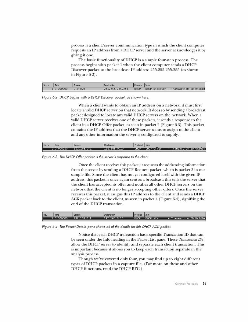
process is a client/server communication type in which the client computer requests an IP address from a DHCP server and the server acknowledges it by giving it one.
The basic functionality of DHCP is a simple four-step process. The process begins with packet 1 when the client computer sends a DHCP Discover packet to the broadcast IP address 255.255.255.255 (as shown in Figure 6-2).
Figure 6-2: DHCP begins with a DHCP Discover packet, as shown here.
When a client wants to obtain an IP address on a network, it must first locate a valid DHCP server on that network. It does so by sending a broadcast packet designed to locate any valid DHCP servers on the network. When a valid DHCP server receives one of these packets, it sends a response to the client in a DHCP Offer packet, as seen in packet 2 (Figure 6-3). This packet contains the IP address that the DHCP server wants to assign to the client and any other information the server is configured to supply.
Figure 6-3: The DHCP Offer packet is the server’s response to the client.
Once the client receives this packet, it requests the addressing information from the server by sending a DHCP Request packet, which is packet 3 in our sample file. Since the client has not yet configured itself with the given IP address, this packet is once again sent as a broadcast; this tells the server that the client has accepted its offer and notifies all other DHCP servers on the network that the client is no longer accepting other offers. Once the server receives this packet, it assigns this IP address to the client and sends a DHCP ACK packet back to the client, as seen in packet 4 (Figure 6-4), signifying the end of the DHCP transaction.
Figure 6-4: The Packet Details pane shows all of the details for this DHCP ACK packet.
Notice that each DHCP transaction has a specific Transaction ID that can be seen under the Info heading in the Packet List pane. These Transaction IDs allow the DHCP server to identify and separate each client transaction. This is important because it allows you to keep each transaction separate in the analysis process.
Though we’ve covered only four, you may find up to eight different types of DHCP packets in a capture file. (For more on these and other DHCP functions, read the DHCP RFC.)

64 Chapter 6
TCP/IP and HTTP
http.pcap
TCP/IP is the basis for almost all of the communication we will discuss in this book. Because it is the most widely used network protocol, we will focus on it.
Hypertext Transfer Protocol (HTTP, RFC 2616) is the server/client–based protocol used to transfer web pages across a network. A simple HTTP transaction is a good example of TCP/IP communication. Every time you search the Internet with Google, check the weather, or even check your fantasy sports teams, you are transferring data via TCP/IP using HTTP.
TCP/IP
The TCP/IP protocol is really a stack of protocols, consisting of several different protocols on both Layers 3 and 4 of the OSI model. These protocols include TCP, IP, ARP, DHCP, ICMP, and many others.
Transmission Control Protocol (TCP, RFC 793) is a Layer 4 protocol that is commonly used because it provides an efficient method of transparent, reliable, and bi-directional communication between devices. Bi-directional communication means that data can be transmitted and received simul-taneously from a single host.
All of the various benefits and features of TCP are made possible through different types of TCP packets and flags. In the next several paragraphs we will look at these different types of packets and what they do.
Internet Protocol (IP, RFC 791) is the Layer 3 protocol that provides the addressing system that allows communication on a network. IP is a connection-less protocol, which means that it requires the functionality of TCP bundled with it to ensure the reliability of transmitted data.
The traffic in the capture file begins with the establishment of a TCP/IP session, followed by the request and transmission of HTTP data and the termination of the session. Stepping through this simple communication between client and server is going to help us in understanding how TCP and IP work.
Establishing the Session
Before you can transfer data to or from another computer, the sender and receiver need to complete a TCP handshake. A TCP handshake is a three-step process whereby the transmitting computer (the client, in this example) establishes a connection with the destination computer (the server). You can see the handshake in the first three packets of our capture file, and it is detailed visually in Figure 6-5.
Now is a very good time to go ahead and establish our client and server computers. The client computer is shown in the first packet with IP address 145.254.160.237. The server computer is shown in the first packet with IP address 65.208.228.223.

Common Pro tocols 65
Figure 6-5: The three-step TCP handshake process
The SYN Packet
To begin the handshake process, the client sends a SYN packet to the server; this packet is designed to establish synchronization with the server, which ensures that the client and server keep their communications in the proper order. The SYN packet carries with it a 32-bit sequence number, located in the header of a TCP packet.
To view a packet’s TCP information, including its sequence number, expand the TCP section under Wireshark’s Packet Details pane. (You will refer to this section often because it contains a variety of useful information, including the source and destination ports used, the sequence number, the type of TCP packet, and other TCP-specific options.) Notice in the capture file that the first SYN packet’s sequence number is 0, as shown in Figure 6-6.
Figure 6-6: The Packet Details pane gives you all the information you need about this packet.
NOTE In Wireshark, TCP sequence numbers are treated as “relative” by default. Wireshark adjusts the first sequence number in a communication stream so that it is 0 rather than its true value. This is done so that the sequence numbers are easier to follow.
SYN/ACK, the Server Response
The next step in the handshake process is the response from the server. Once the server receives the initial SYN packet from the client, it reads the packet’s sequence number and uses that number in the packet it returns. The response packet is called a SYN/ACK packet, and it is seen in packet 2 of the example file.
ACK PacketSeq # 222222222Ack # 111111112
SYN PacketSeq # 111111111Ack # 0
SYN PacketSeq # 111111112Ack # 222222223Client Server
66 Chapter 6
The ACK portion of the packet acknowledges the SYN packet—in other words, it tells the client computer that the server received the SYN packet. It does this by incrementing the sequence number sent in the original SYN packet by one and using it as the acknowledgment number in the ACK packet. When the client receives this acknowledgment number containing the original SYN sequence number, it knows that the server can receive its communication, and vice versa. The purpose of SYN portion of the SYN/ACK is the same as in the original SYN packet: It is used to transmit a sequence number that the client system can use to acknowledge receipt.
The Final ACK Packet
Finally, the client sends an ACK packet to the server. This packet tells the server that the client received its SYN/ACK packet. As with step two of the process, the sequence number is incremented by one and sent as an acknowledgment number to the server. Once this last ACK packet is received, communication can begin.
Beginning the Flow of Data
Once the handshake has been established, all packets sent in this particular session between client and server will use sequence numbers to make sure they stay in order. However, from now on, these packets will be incremented by the size of the data frame being transmitted, rather than by one. (To learn more about how TCP packets stay organized, have a look at RFC 793.)
HTTP Request and TransmissionOnce the communication session has been established, it’s time for the actual request and transmission of the web page you are trying to view. This involves both HTTP and TCP.
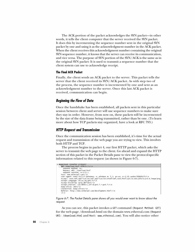
The process begins in packet 4, our first HTTP packet, which asks the server to transmit the web page to the client. Go ahead and expand the HTTP section of this packet in the Packet Details pane to view the protocol-specific information related to this request (as shown in Figure 6-7).
Figure 6-7: The Packet Details pane shows all you would ever want to know about the request.
As you can see, this packet invokes a GET command (Request Method: GET) for the web page /download.html on the domain www.ethereal.com (Request URI: /download.html and Host: www.ethereal.com). You will also notice other
Common Pro tocols 67
information that may be useful, such as character encoding (Accept-Charset: ISO-8859-1), and the referrer location (Referrer: http://www.ethereal.com/development.html \r \n).
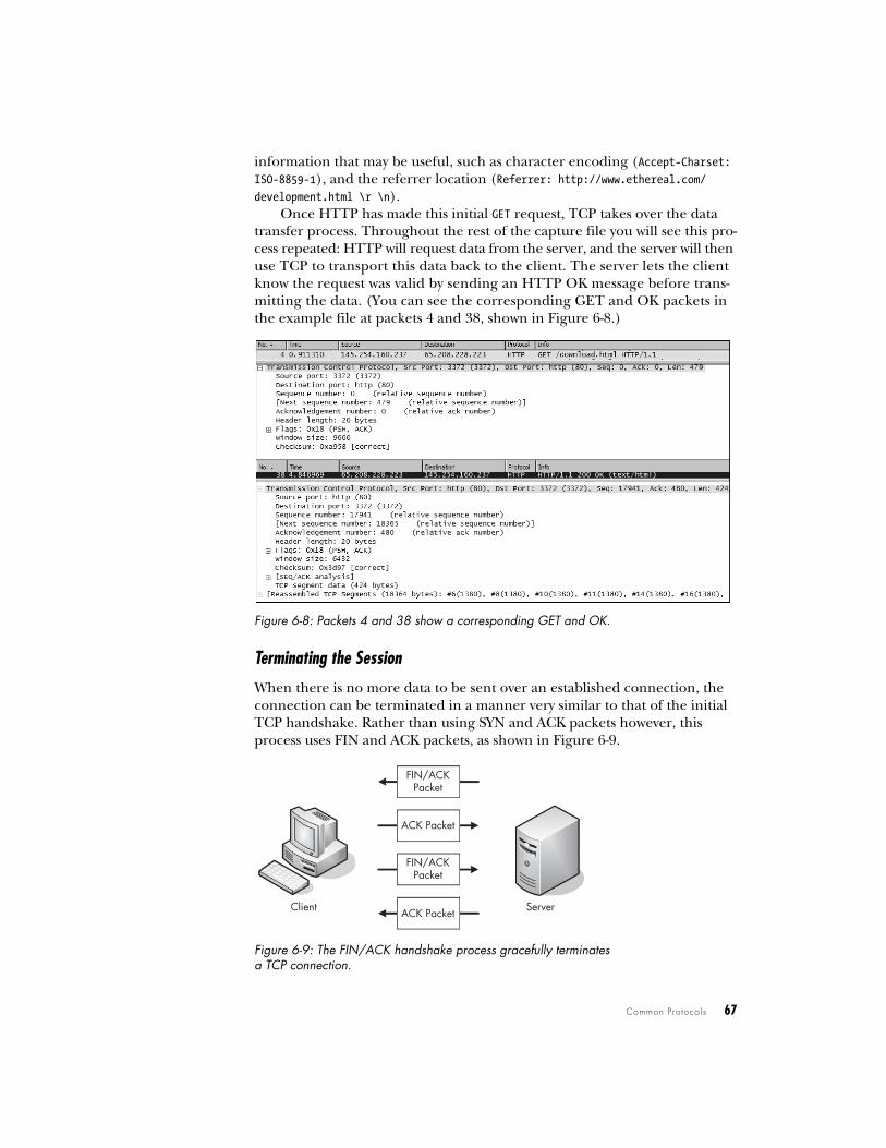
Once HTTP has made this initial GET request, TCP takes over the data transfer process. Throughout the rest of the capture file you will see this pro-cess repeated: HTTP will request data from the server, and the server will then use TCP to transport this data back to the client. The server lets the client know the request was valid by sending an HTTP OK message before trans-mitting the data. (You can see the corresponding GET and OK packets in the example file at packets 4 and 38, shown in Figure 6-8.)
Figure 6-8: Packets 4 and 38 show a corresponding GET and OK.
Terminating the Session
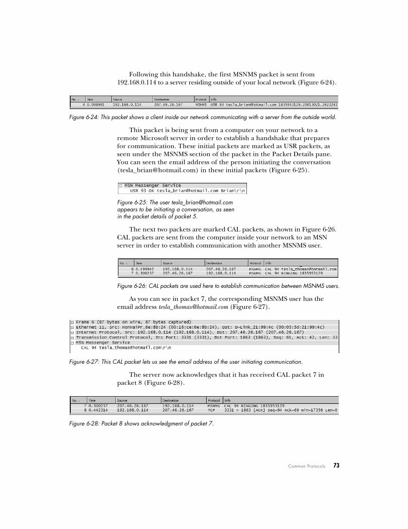
When there is no more data to be sent over an established connection, the connection can be terminated in a manner very similar to that of the initial TCP handshake. Rather than using SYN and ACK packets however, this process uses FIN and ACK packets, as shown in Figure 6-9.
Figure 6-9: The FIN/ACK handshake process gracefully terminates a TCP connection.
Client Server
FIN/ACKPacket
ACK Packet
FIN/ACKPacket
ACK Packet

68 Chapter 6
When the server finishes transmitting data, it sends a FIN/ACK packet to the client, as shown in Figure 6-10. The FIN packet is designed to gracefully close a connection.
Figure 6-10: You can see the details of a FIN/ACK packet in the Packet Details pane.
The client responds to the FIN packet with an ACK packet that uses the sequence numbers and incrementation rules that it finds in the FIN packet. This closes communication from the server’s end of things. While the server can still receive data from the client at this point, it will no longer transmit data.
To complete the process, the client must initiate this same process again with the server. The FIN/ACK process must be initiated and acknowledged by both the client and server.
For example, in packet 40, the server sends a FIN/ACK packet to the client, and the client responds with its ACK packet in packet 41. Following that, the client sends its own FIN/ACK packet to the server, and the server closes the connection with an ACK packet, packet 43, as shown in Figure 6-11.
Figure 6-11: The FIN/ACK process as seen from the Packet List pane
Domain Name System
dns.pcap
The Domain Name System (DNS, RFC 1034) translates one form of address into another—specifically, it translates DNS addresses, such as www.google.com or MARKETING-PC1, into their corresponding IP addresses. Some form of address translation is a requirement, since Layer 3 of the OSI model can only locate a computer if it has its IP address.
DNS translation is a very simple process, and it gets the job done in most cases using only two packets. The first packet is a request to your network’s local DNS server that asks, What is the IP address of www.google.com? The second packet is the response from that DNS server, saying that www.google.com resides on a server with an IP address of XX.XX.XX.XXX.
Let’s take a look at DNS in action (see Figure 6-12). Notice in the first packet of the file that a DNS packet from source 192.168.0.114 is requesting the IP address of http://www.chrissanders.org from destination 205.152.37.23. The destination IP address receives the query and responds with packet 2,

Common Pro tocols 69
which contains the IP address of the requested website, 208.113.140.24. Once this process is complete, Layer 3 can take over and complete its TCP handshake so that data transfer can begin.
Figure 6-12: DNS only requires two packets—a request and a response.
NOTE As you examine the actual sample capture file, you will see several different DNS queries taking place. Often a single web page will invoke a number of queries because the information needs to be retrieved from several servers. Try creating a display filter to show only the DNS traffic and see if you can determine how many different DNS queries take place in this file.
File Transfer Protocol
ftp.pcap
The File Transfer Protocol (FTP, RFC 959) is a Layer 7 protocol that is used to transfer data between a server and client. Operating on ports 20 and 21, FTP is one of the most commonly used file transfer utilities. Because FTP is a client/server protocol, all communication in the capture file involves back-and-forth traffic between a client computer and a server computer. As with all TCP processes, FTP begins with a standard TCP handshake, as shown with packet 1 and in Figure 6-13 below.
Figure 6-13: The TCP handshake is prevalent in various communication types.
Once the handshake process completes, the server sends a welcome message to the client. This message identifies the server as an FTP server and tells the client that the server is ready to accept its login credentials, as shown in Figure 6-14.
Figure 6-14: The beginning of the FTP communication process
Through the next several packets, the client sends a username (csanders) and a password (echo) to the server, and the server acknowledges them (Figure 6-15).
Figure 6-15: The username and password of the FTP user being transmitted to the server

70 Chapter 6
This communication is summed up nicely in the Info column of the Packet List pane, though that window only gives a very brief summary of the packet contents. If you want to dig a little deeper, you can expand the FTP section in the Packet Details pane.
Notice that encryption is not used in our example, so the FTP password can be seen clearly in the capture file in packet 7 (Figure 6-16).
Figure 6-16: The password of the user csanders can be seen clearly in this packet.
CWD Command
As you can see, packet 15 shows a CWD command being sent from the client to the server. CWD stands for change working directory, and this command is invoked every time you tell an FTP client to move to a different directory on the server.
Notice in this example that the CWD command includes requests to change the working directory to /, which is the root directory of the FTP server. When you first log into an FTP server, the CWD command is issued to change to the root directory, /. Once the server receives this CWD command, it changes to the root directory and tells the client that / is now the current working directory.
A connecting client uses a list of commands to interact with an FTP server. These range from viewing the contents of a directory, traversing a directory, download-ing or deleting a file, and so on. (For a complete list of the available commands visible in an FTP packet, see RFC 959.) Let’s look at a few FTP commands used in our example file, beginning with packet 15, shown in Figure 6-17.
Figure 6-17: Packet 15 shows the PWD command being issued to the server.
SIZE Command
The next command is the SIZE command, shown in Figure 6-18. This command reports the size (in bytes) of a particular file, and it is always sent with a filename.
Figure 6-18: The SIZE command being sent to the server

Common Pro tocols 71
the RETR command to the server, requesting download of the file Music.mp3. Once the server gets this request, it begins sending the data to the client.
NOTE The packets labeled FTP-DATA are ones containing a file that is being downloaded from or uploaded to the server.
Telnet Protocol
telnet.pcap
The telnet protocol (RFC 854) is an unsecured, text-based way for a server and client to communicate. It is often used to remotely administer servers, switches, routers, and other network hardware devices.
In this capture file you will see an example of a client computer (192.168.0.2) connecting to a telnet server (192.168.0.1). As you begin to step through the data being transmitted, notice that everything is sent in clear text. For this reason, the telnet protocol should not be used to transmit sensitive data.
NOTE You can be more secure by forgoing telnet and using SSH instead.
Each telnet session uses several unique options to specify communication rates and data transfer modes, which must be synchronized between client
Notice in packet 25 that the client sends the SIZE command to the server to request the size of the file Music.mp3. Packet 26 (Figure 6-19) shows the server’s response, which is the file size of 4,980,924 bytes.
Figure 6-19: The packet returned from the issued SIZE command
RETR Command
The RETR (retrieve) command, shown in Figure 6-20, is used by the client to request the down-load of a file from the server. In packet 32, the client sends
Figure 6-20: The RETR command is used to download a file from the FTP server.
What type of communi-cation is occurring in this exchange between server and client? Starting at the top, we can immediately draw several conclusions. The first several packets confirm that we are definitely seeing telnet traffic, because telnet-specific settings are being communicated between these two devices, as shown in Figure 6-21.
Figure 6-21: The first packets of the capture file are telnet packets between server and client.

72 Chapter 6
and server before communication can begin. These options account for the first 30 or so packets in the sample capture file.
The first interesting packet is number 27, which identifies the server as an OpenBSD server. Packet 29 presents a login prompt to the client, and in packet 31 you can see that the username fake is sent back to the server. Packet 36 requests a password from the client, which is answered in packet 38 with the password user, which is shown in Figure 6-22. You can now see just how insecure telnet is. This username and password combination could very well be the administrative password to one of the most important servers on your network, and it would still be shown in clear text that is readable by anyone with a packet sniffer and little bit of knowledge.
Figure 6-22: A password transmitted via telnet can be seen as clear as day.
The rest of the capture file shows the client using the established telnet session to ping several websites. You can observe this data and exactly how it is transferred by looking at the telnet section in the Packet Details pane.
MSN Messenger Service
msnms.pcap
You may find that you need to analyze the traffic of an instant message con-versation for several reasons. We explored one possible scenario in Chapter 5 when we suspected an employee of giving away company financial informa-tion over messenger software. There are several popular instant messaging applications, and while each one utilizes its own protocol, there are certain similarities in each. Here we’ll focus specifically on traffic from the MSN Messenger Service (MSNMS). Let’s see if we can’t catch some employees in the act.
NOTE Some organizations have policies that prevent the use of messaging software, and if so, even seeing the MSNMS protocol in a capture file can set off alarms.
The capture file begins like any TCP communication—with a simple handshake between two clients, as shown in Figure 6-23.
Figure 6-23: The TCP handshake begins the communication process.
Common Pro tocols 73
Following this handshake, the first MSNMS packet is sent from 192.168.0.114 to a server residing outside of your local network (Figure 6-24).
Figure 6-24: This packet shows a client inside our network communicating with a server from the outside world.
This packet is being sent from a computer on your network to a remote Microsoft server in order to establish a handshake that prepares for communication. These initial packets are marked as USR packets, as seen under the MSNMS section of the packet in the Packet Details pane. You can seen the email address of the person initiating the conversation ([email protected]) in these initial packets (Figure 6-25).
Figure 6-25: The user [email protected] appears to be initiating a conversation, as seen in the packet details of packet 5.
The next two packets are marked CAL packets, as shown in Figure 6-26. CAL packets are sent from the computer inside your network to an MSN server in order to establish communication with another MSNMS user.
Figure 6-26: CAL packets are used here to establish communication between MSNMS users.
As you can see in packet 7, the corresponding MSNMS user has the email address [email protected] (Figure 6-27).
Figure 6-27: This CAL packet lets us see the email address of the user initiating communication.
The server now acknowledges that it has received CAL packet 7 in packet 8 (Figure 6-28).
Figure 6-28: Packet 8 shows acknowledgment of packet 7.
74 Chapter 6
Packet 9 is the last packet to be sent to fully establish communication. As shown in Figure 6-29, packet 9 is a JOI packet sent from the remote MSN servers, indicating that the other member of the party ([email protected], in this case) has successfully joined a session and can establish communication.
Figure 6-29: Packet 9 is a JOI packet indicating that the users are now sharing a session.
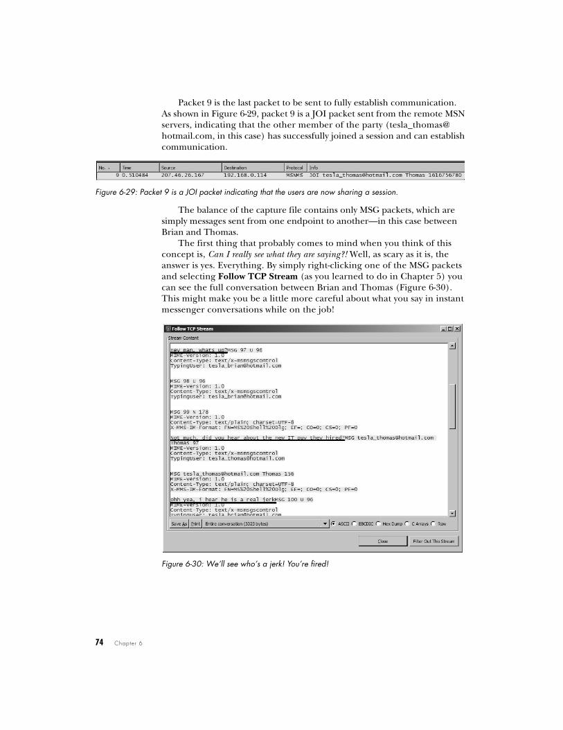
The balance of the capture file contains only MSG packets, which are simply messages sent from one endpoint to another—in this case between Brian and Thomas.
The first thing that probably comes to mind when you think of this concept is, Can I really see what they are saying?! Well, as scary as it is, the answer is yes. Everything. By simply right-clicking one of the MSG packets and selecting Follow TCP Stream (as you learned to do in Chapter 5) you can see the full conversation between Brian and Thomas (Figure 6-30). This might make you be a little more careful about what you say in instant messenger conversations while on the job!
Figure 6-30: We’ll see who’s a jerk! You’re fired!

Common Pro tocols 75
Internet Control Message Protocol
icmp.pcap
Internet Control Message Protocol (ICMP) is a part of the IP protocol; I like to call it a utility protocol because it’s used for troubleshooting other protocols. If you have ever used the ping utility, you have used the ICMP protocol.
Let’s see what common ICMP traffic looks like. The included capture file only contains eight packets. There are two separate pings to two separate hosts. Let’s look at the packet details of packet 1, shown in Figure 6-31.
Common sense tells us that if a computer sends an echo request, it should receive an echo reply, and that’s just what we see in the capture file. Packet 2 is transmitted back from the remote computer and is marked as ICMP type 0, an echo (ping) reply.
A standard ping from a Windows command line pings a host four times. You can see the ping process in the capture file and in Figure 6-32, as well. The first ping destination, 192.168.0.1, receives and replies to four pings. Following this, another ping is initiated to 72.14.207.99 (http://www.google.com), which also receives and replies to four pings.
Figure 6-32: Ping, reply, ping, reply, ping, reply—you get the picture, right?
Final Thoughts
The goal of this chapter has been to introduce you to using Wireshark to analyze capture files and to use those capture files to show you how some common protocols work. Although we’ve only briefly covered some of the more advanced protocols, I highly recommend reading their RFCs and studying them more in depth. As the book continues on to various sce-narios, we will be building on the basic concepts you’ve learned here.
If you expand the ICMP section, you will see what little there is to an ICMP packet. The first packet is labeled as type 8, an echo (ping) request. Every ICMP packet has a numerical type associated with it, which determines how the packet is to be handled by the destination machine. (RFC 792 lists all the different types of ICMP packets.)
Figure 6-31: The first ping packet, packet 1