Embed Size (px)
Citation preview
Common Rail Injector Tester
AUTO DITEX BG Ltd. www.autoditex.com
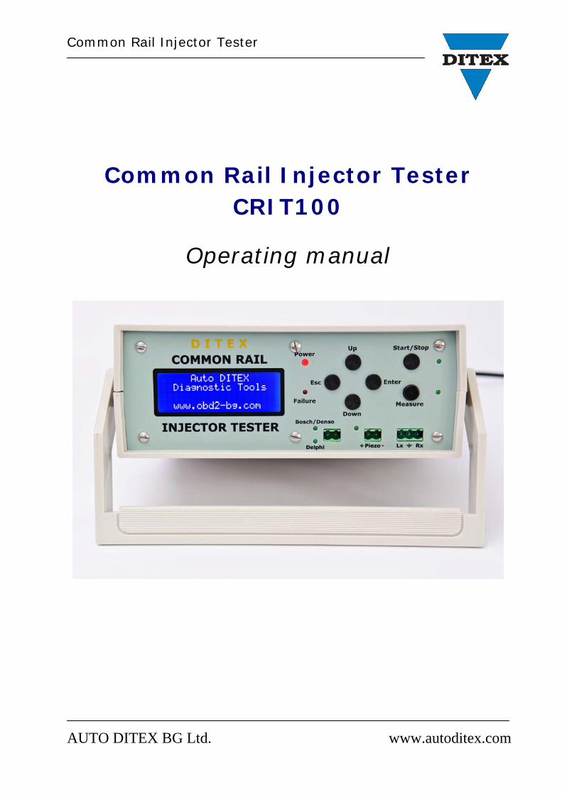
Common Rail Injector Tester CRIT100
Operating manual
Common Rail Injector Tester
AUTO DITEX BG Ltd. www.autoditex.com
Contents
Introduction ………………..………………………………………………………………………… page 3
Technical specifications .…………………………………………………………………...... page 3
Typical applications……………………………………………………………………….………. page 4
Device appearance ..................................................................... page 5
Operation of the Common Rail Injector Tester CRIT100……………………… page 6
Working modes description........………………………………………………………… page 7
Definition of terms.........……………………………………………………………………… page 12
How start an injector test?.......................……………………………………….. page 13
How to measure an injector resistance?....................…………………….. page 14
How to measure an injector inductance?....................…………………... page 15
Standard package list ………………………………………………………………………… page 16
Common Rail Injector Tester
AUTO DITEX BG Ltd. www.autoditex.com
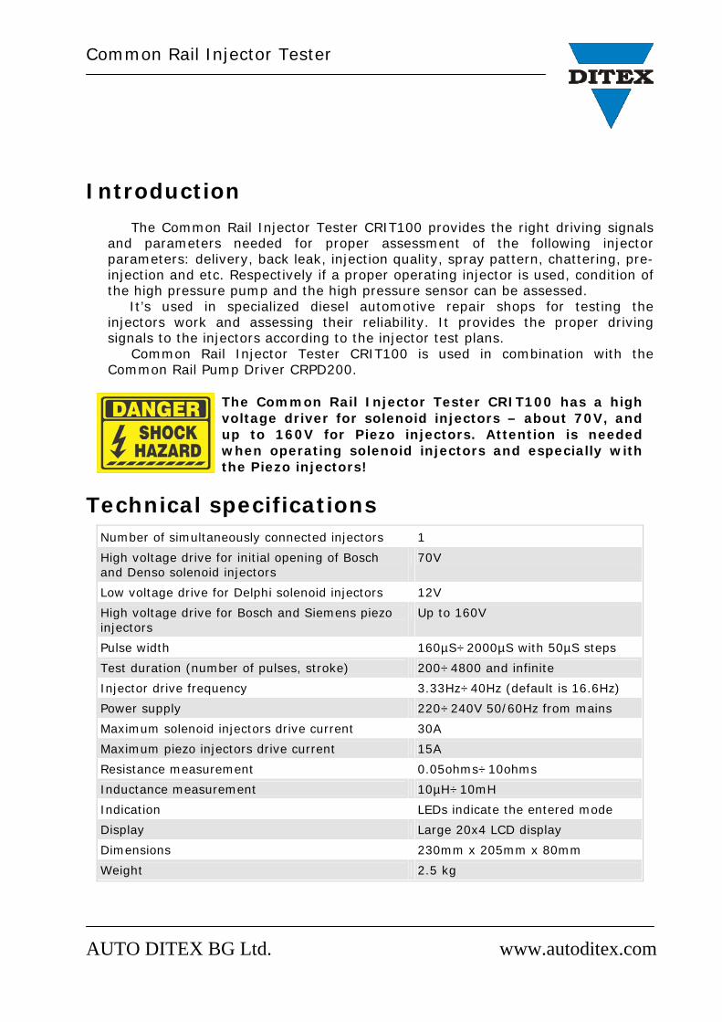
Introduction The Common Rail Injector Tester CRIT100 provides the right driving signals and parameters needed for proper assessment of the following injector parameters: delivery, back leak, injection quality, spray pattern, chattering, pre-injection and etc. Respectively if a proper operating injector is used, condition of the high pressure pump and the high pressure sensor can be assessed.
It’s used in specialized diesel automotive repair shops for testing the injectors work and assessing their reliability. It provides the proper driving signals to the injectors according to the injector test plans. Common Rail Injector Tester CRIT100 is used in combination with the Common Rail Pump Driver CRPD200.
The Common Rail Injector Tester CRIT100 has a high voltage driver for solenoid injectors – about 70V, and up to 160V for Piezo injectors. Attention is needed when operating solenoid injectors and especially with the Piezo injectors!
Technical specifications Number of simultaneously connected injectors 1 High voltage drive for initial opening of Bosch and Denso solenoid injectors
70V
Low voltage drive for Delphi solenoid injectors 12V High voltage drive for Bosch and Siemens piezo injectors
Up to 160V
Pulse width 160µS÷2000µS with 50µS steps Test duration (number of pulses, stroke) 200÷4800 and infinite Injector drive frequency 3.33Hz÷40Hz (default is 16.6Hz) Power supply 220÷240V 50/60Hz from mains Maximum solenoid injectors drive current 30A Maximum piezo injectors drive current 15A Resistance measurement 0.05ohms÷10ohms Inductance measurement 10µH÷10mH Indication LEDs indicate the entered mode Display Large 20x4 LCD display Dimensions 230mm x 205mm x 80mm Weight 2.5 kg
Common Rail Injector Tester
AUTO DITEX BG Ltd. www.autoditex.com
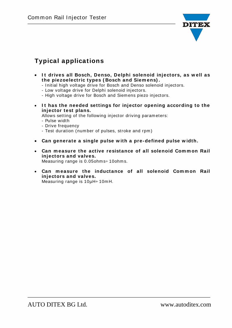
Typical applications
It drives all Bosch, Denso, Delphi solenoid injectors, as well as the piezoelectric types (Bosch and Siemens). - Initial high voltage drive for Bosch and Denso solenoid injectors. - Low voltage drive for Delphi solenoid injectors. - High voltage drive for Bosch and Siemens piezo injectors.
It has the needed settings for injector opening according to the injector test plans. Allows setting of the following injector driving parameters: - Pulse width - Drive frequency - Test duration (number of pulses, stroke and rpm)
Can generate a single pulse with a pre-defined pulse width.
Can measure the active resistance of all solenoid Common Rail injectors and valves. Measuring range is 0.05ohms÷10ohms.
Can measure the inductance of all solenoid Common Rail injectors and valves. Measuring range is 10µH÷10mH.
Common Rail Injector Tester
AUTO DITEX BG Ltd. www.autoditex.com
Common Rail Injector Tester CRIT100
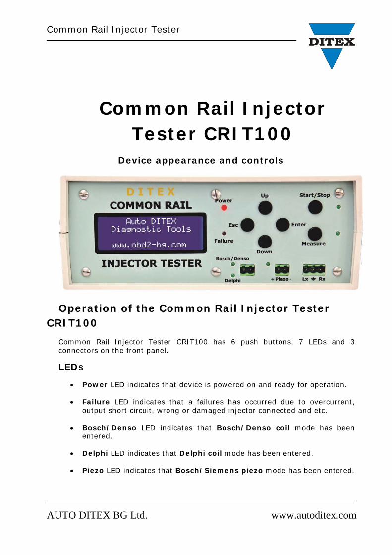
Device appearance and controls
Operation of the Common Rail Injector Tester CRIT100
Common Rail Injector Tester CRIT100 has 6 push buttons, 7 LEDs and 3 connectors on the front panel. LEDs
Power LED indicates that device is powered on and ready for operation.
Failure LED indicates that a failures has occurred due to overcurrent, output short circuit, wrong or damaged injector connected and etc.
Bosch/Denso LED indicates that Bosch/Denso coil mode has been
entered.
Delphi LED indicates that Delphi coil mode has been entered.
Piezo LED indicates that Bosch/Siemens piezo mode has been entered.
Common Rail Injector Tester
AUTO DITEX BG Ltd. www.autoditex.com
Start/Stop LED flashes with the injector frequency when a test has been
started.
Measure LED indicates that CR injector R meter or CR injector L meter modes are entered.
Buttons Changing the operating mode and starting a measurement, as well as the change in the parameters of generated signal, is made by means of 6 push buttons – Up, Down, Esc, Enter, Start/Stop and Measure.
Use Up and Down buttons to select operating mode and to change the value of the parameter already chosen.
Use the Enter button to enter a submenu or to confirm the choice.
Use the Esc button to go back into the pervious menu. If after the choice
of the parameter the Enter button is not pushed, but only Esc button, the new value will be also kept.
Use the Start/Stop button to start injector test when an operation mode
is previously selected.
Measure button is used to start a measurement of resistance or inductance and it’s active only when CR injector R meter or CR injector L meter modes are selected.
Connectors
There are 3 connectors on the front panel:
2 pin connector for Bosch, Denso and Delphi solenoid injectors
2 pin connector for Bosch and Siemens piezo injectors
3 pin connector for measuring resistance and inductance of solenoid injectors and valves.
As soon as the power supply of the Common Rail Injector Tester CRIT100 is switched off, all the settings, previously done are lost. There is no possibility to remember the settings. At the next turn on of the device, the default settings are loaded.
Common Rail Injector Tester
AUTO DITEX BG Ltd. www.autoditex.com
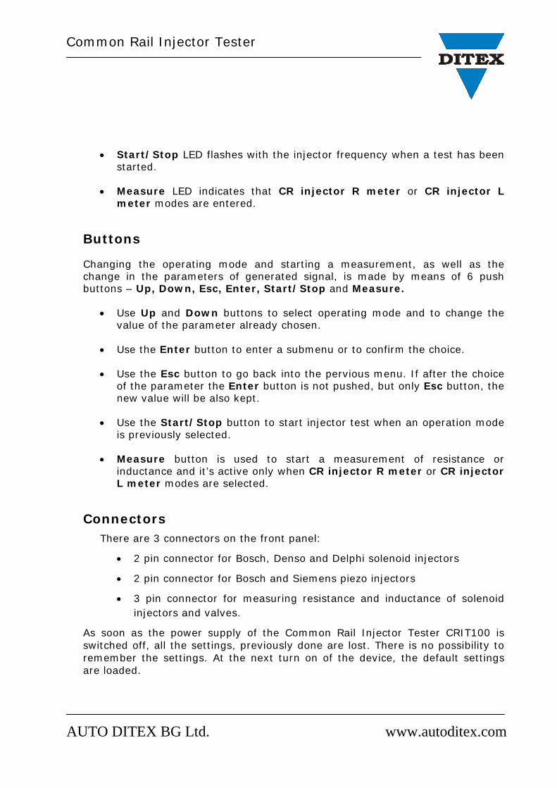
Working modes
Fig.1 Main menu
1. Bosch/Denso coil
Pulse width 160uS ~ 2000uS (with 50uS steps)
Cycle (strok) 1 ~ 4800 and infinite
RPM (IPM) 100 ~ 2400 (3.33Hz ~ 40Hz)
Fig.2 Mode Bosch/Denso coil – Pulse width adjustment
Fig.3 Mode Bosch/Denso coil – Cycle (strok) adjustment
Fig.4 Mode Bosch/Denso coil – RPM (IPM) adjustment
Common Rail Injector Tester
AUTO DITEX BG Ltd. www.autoditex.com
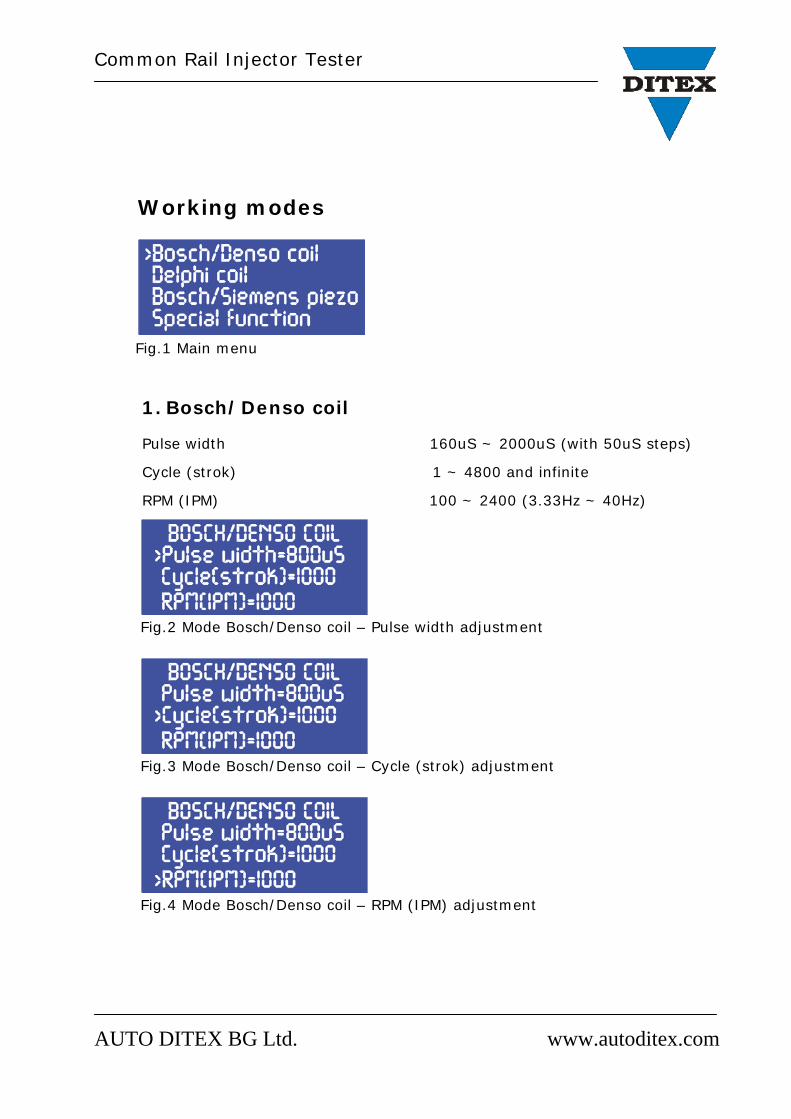
2. Delphi coil Pulse width 160uS ~ 2000uS (with 50uS steps)
Cycle (strok) 1 ~ 4800 and infinite
RPM (IPM) 100 ~ 2400 (3.33Hz ~ 40Hz)
Fig.5 Mode Bosch/Denso coil – Pulse width adjustment
Fig.6 Mode Bosch/Denso coil – Cycle (strok) adjustment
Fig.7 Mode Bosch/Denso coil – RPM (IPM) adjustment
3. Bosch/Siemens piezo
Pulse width 160uS ~ 2000uS (with 50uS steps)
Cycle (strok) 1 ~ 4800 and infinite
RPM (IPM) 100 ~ 2400 (3.33Hz ~ 40Hz)
Common Rail Injector Tester
AUTO DITEX BG Ltd. www.autoditex.com
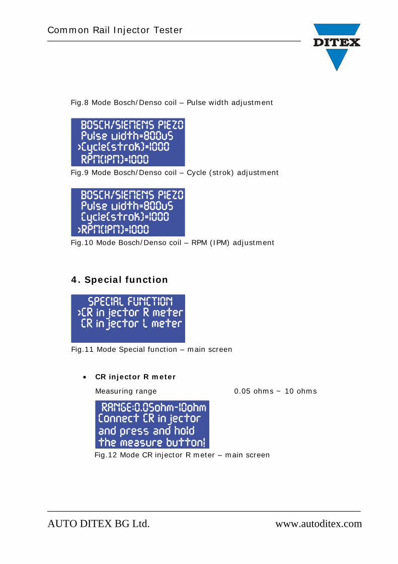
Fig.8 Mode Bosch/Denso coil – Pulse width adjustment
Fig.9 Mode Bosch/Denso coil – Cycle (strok) adjustment
Fig.10 Mode Bosch/Denso coil – RPM (IPM) adjustment
4. Special function
Fig.11 Mode Special function – main screen
CR injector R meter
Measuring range 0.05 ohms ~ 10 ohms
Fig.12 Mode CR injector R meter – main screen
Common Rail Injector Tester
AUTO DITEX BG Ltd. www.autoditex.com
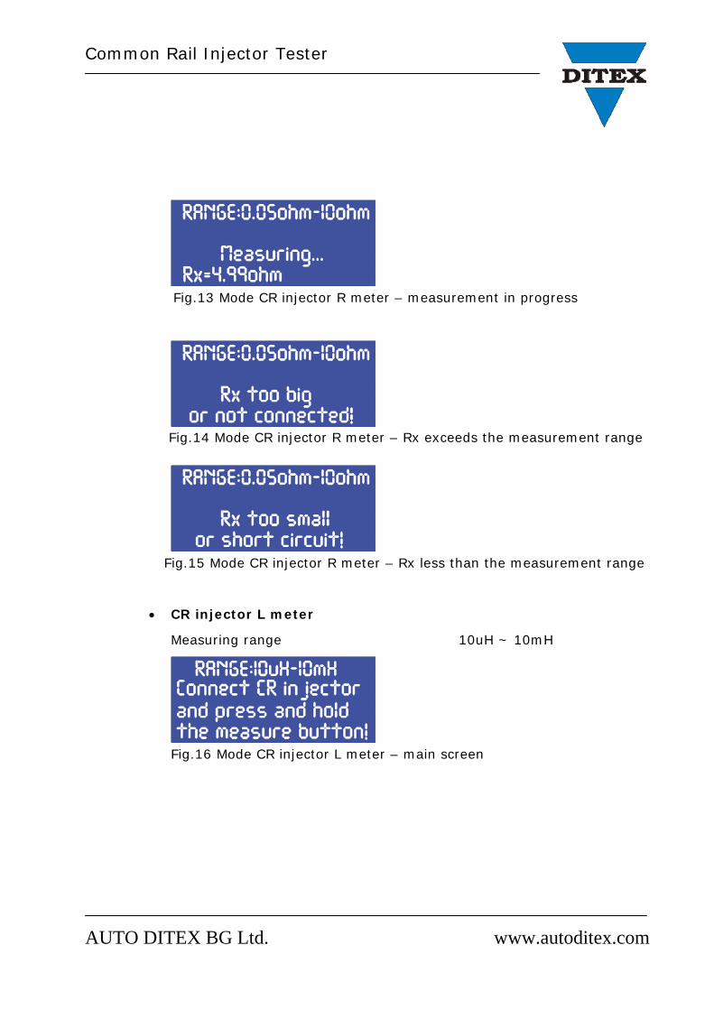
Fig.13 Mode CR injector R meter – measurement in progress
Fig.14 Mode CR injector R meter – Rx exceeds the measurement range
Fig.15 Mode CR injector R meter – Rx less than the measurement range
CR injector L meter
Measuring range 10uH ~ 10mH
Fig.16 Mode CR injector L meter – main screen
Common Rail Injector Tester
AUTO DITEX BG Ltd. www.autoditex.com
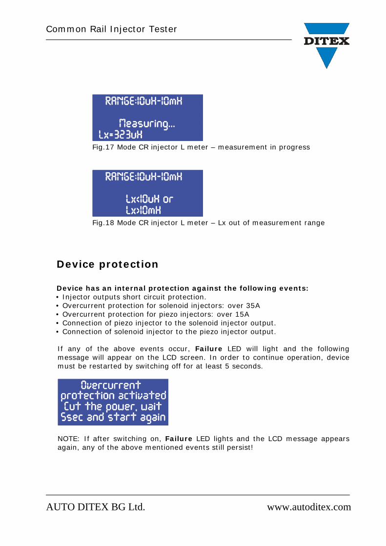
Fig.17 Mode CR injector L meter – measurement in progress
Fig.18 Mode CR injector L meter – Lx out of measurement range
Device protection
Device has an internal protection against the following events: • Injector outputs short circuit protection. • Overcurrent protection for solenoid injectors: over 35A • Overcurrent protection for piezo injectors: over 15A • Connection of piezo injector to the solenoid injector output. • Connection of solenoid injector to the piezo injector output.
If any of the above events occur, Failure LED will light and the following message will appear on the LCD screen. In order to continue operation, device must be restarted by switching off for at least 5 seconds.
NOTE: If after switching on, Failure LED lights and the LCD message appears again, any of the above mentioned events still persist!
Common Rail Injector Tester
AUTO DITEX BG Ltd. www.autoditex.com
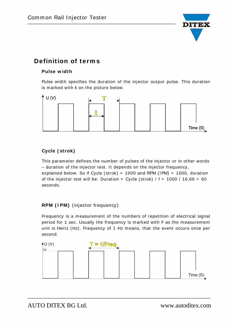
Definition of terms Pulse width
Pulse width specifies the duration of the injector output pulse. This duration is marked with t on the picture below.
Cycle (strok)
This parameter defines the number of pulses of the injector or in other words – duration of the injector test. It depends on the injector frequency, explained below. So if Cycle (strok) = 1000 and RPM (IPM) = 1000, duration of the injector test will be: Duration = Cycle (strok) / f = 1000 / 16,66 = 60 seconds.
RPM (IPM) (injector frequency)
Frequency is a measurement of the numbers of repetition of electrical signal period for 1 sec. Usually the frequency is marked with F as the measurement unit is Hertz (Hz). Frequency of 1 Hz means, that the event occurs once per second.
Common Rail Injector Tester
AUTO DITEX BG Ltd. www.autoditex.com
Interval of time in which some event repeats is called period. In the SI system the period is marked with T and it is measured in seconds [s]. The period T is inversely proportional to the frequency and the formula for calculation is T = 1 / f.
In the particular case as an injector tester, this parameter is called RPM (revolutions per minute) or IPM (impulses per minute). So if on the screen RPM (IPM) = 1000, it means f = RPM (IPM) / 60 = 1000 / 60 = 16,66Hz. Number 60 means 1 minute which has 60 seconds.
How to start an injector test?
o Identify the type (solenoid or piezo) and brand of the injector (Bosch, Denso, Delphi or Siemens).
o Connect the injector to the correct test connector of the device. o Switch on the Common Rail Injector Tester CRIT100. o Choose the injector type from the menu. o Select the desired* Pulse width by pressing the Enter button and
change value with Up and Down buttons. Confirm choice with Enter or Esc button.
o Select the desired* Cycle (strok) parameter value by pressing the Enter button and change value with Up and Down buttons. Confirm choice with Enter or Esc button.
o Select the desired* RPM (IPM) parameter value by pressing the Enter button and change value with Up and Down buttons. Confirm choice with Enter or Esc button.
o Press the Start/Stop button to start the injector test. Test will stop after a timeout which depends on the Cycle (strok) and RPM (IPM) values. *Parameter value is chosen according to the current injector test data plan. Injector test data plan (injector test plan or injector calibration data) are list of test parameters unique for each injector.
Common Rail Injector Tester
AUTO DITEX BG Ltd. www.autoditex.com
How to measure injector resistance?
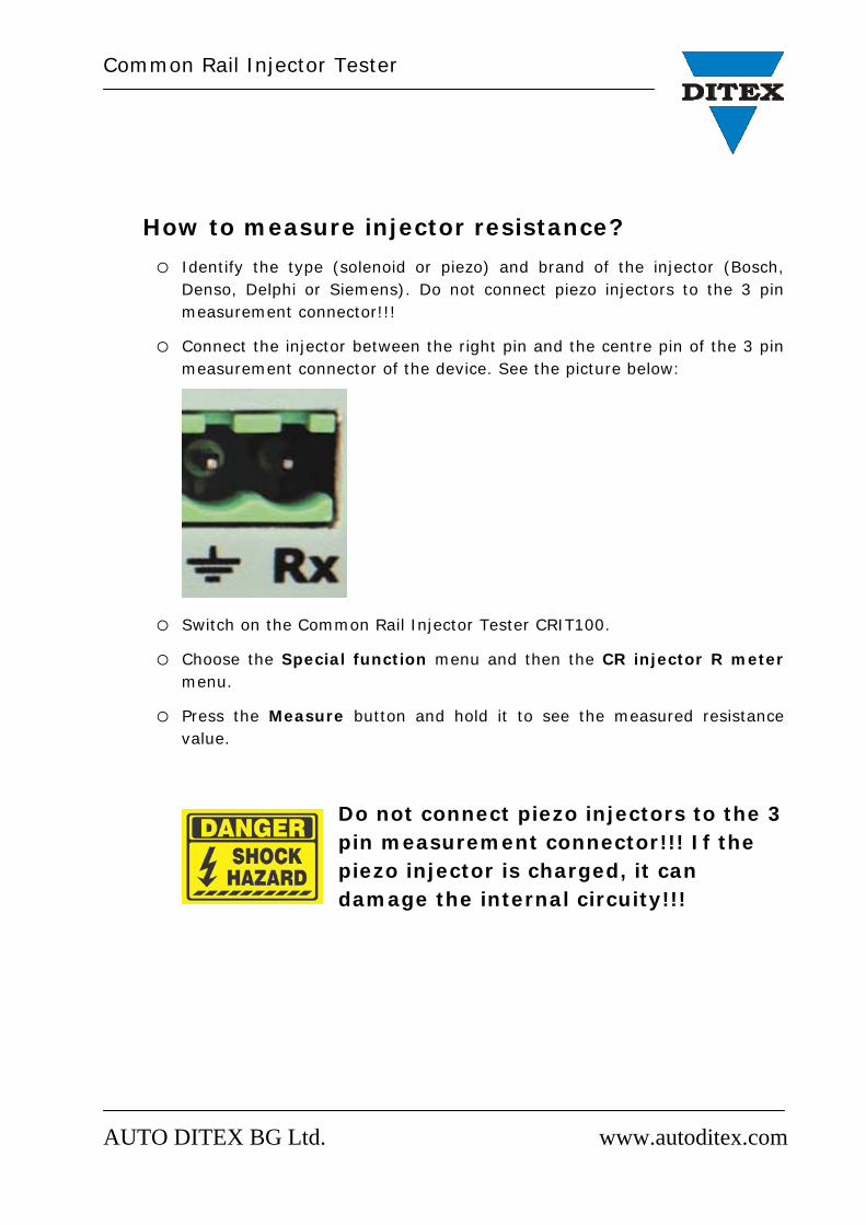
o Identify the type (solenoid or piezo) and brand of the injector (Bosch, Denso, Delphi or Siemens). Do not connect piezo injectors to the 3 pin measurement connector!!!
o Connect the injector between the right pin and the centre pin of the 3 pin measurement connector of the device. See the picture below:
o Switch on the Common Rail Injector Tester CRIT100. o Choose the Special function menu and then the CR injector R meter
menu. o Press the Measure button and hold it to see the measured resistance
value.
Do not connect piezo injectors to the 3 pin measurement connector!!! If the piezo injector is charged, it can damage the internal circuity!!!
Common Rail Injector Tester
AUTO DITEX BG Ltd. www.autoditex.com
How to measure injector inductance?
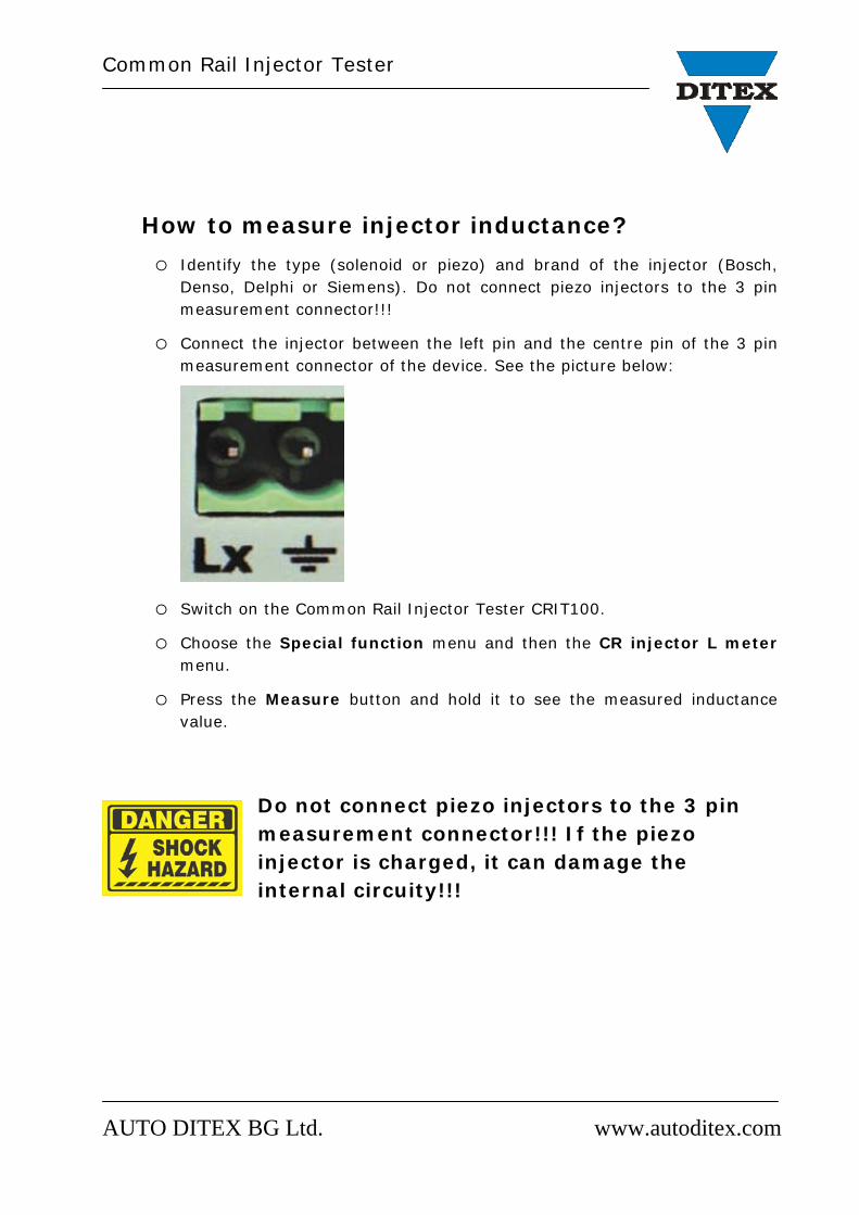
o Identify the type (solenoid or piezo) and brand of the injector (Bosch, Denso, Delphi or Siemens). Do not connect piezo injectors to the 3 pin measurement connector!!!
o Connect the injector between the left pin and the centre pin of the 3 pin measurement connector of the device. See the picture below:
o Switch on the Common Rail Injector Tester CRIT100. o Choose the Special function menu and then the CR injector L meter
menu. o Press the Measure button and hold it to see the measured inductance
value.
Do not connect piezo injectors to the 3 pin measurement connector!!! If the piezo injector is charged, it can damage the internal circuity!!!
Common Rail Injector Tester
AUTO DITEX BG Ltd. www.autoditex.com
Standard package list:
• Common Rail Injector Tester CRIT100 – main unit; • 2 female 2 PIN injector connectors; • 1 female 3 PIN connector for resistance and inductance measurement; • Various injector test plans; • Power supply cable.


![Untitled-2 [3.imimg.com]3.imimg.com/data3/XO/OC/MY-1810869/crdi-test-bench.pdfPUMPSINJECTOR & RAIL TESTER WITH PIEZO INJECTOR TESTING. SALIENT FEATURES AC FREQUENCY INVERTOR DRIVE,](https://img.pdfslide.net/doc/110x75/61049a7472ea0c0c58250194/untitled-2-3imimgcom3imimgcomdata3xoocmy-1810869crdi-test-benchpdf-pumpsinjector.jpg)


![[DESIGN] Piezo-Piezo to Pie](https://img.pdfslide.net/doc/110x75/5571f8bb49795991698df909/design-piezo-piezo-to-pie.jpg)

