Embed Size (px)
Citation preview
VOL. 13, NO. 18, SEPTEMBER 2018 ISSN 1819-6608
ARPN Journal of Engineering and Applied Sciences ©2006-2018 Asian Research Publishing Network (ARPN). All rights reserved.
www.arpnjournals.com
4860
DEVELOPMENT OF DIESEL PIEZO INJECTOR DRIVER USING
MICROCONTROLLERS
Youngju Lee and Choong Hoon Lee
Department of Mechanical and Automotive Engineering, Seoul National University of Science and Technology, Seoul, Korea
E-Mail: [email protected]
ABSTRACT
A diesel piezo injector driver was developed using microcontrollers and MOSFETs. Fuel injection with a
common rail injector is possible when controlling the magnitude of the hydraulic pressure acting on the nozzle needle.
There are two types of solenoids and piezo-electric components to open and close the hydraulic passages acting on the
nozzle needle. A solenoid-type injector is driven by controlling the current waveform supplied to the injector via a peak &
hold approach. The solenoid-type injector driver can be implemented with a circuit that switches the driving power with
one transistor which has a high current capacity. In contrast, a piezo-type injector is driven by the contraction and
expansion of piezoelectric elements that open and close the hydraulic passages to control the movement of the nozzle
needle. In order to control the contraction and expansion of the piezoelectric element in a piezo injector, charge and
discharge control of the current supplied to the injector is required. For this purpose, a pair-switch circuit capable of
charging and discharging the current supplied to the injector has been developed. The driving voltage of the piezo injector
was in the range of 100 ~ 140V. High voltage and current switches were used for charging and discharging. Fuel injection
at a high common rail pressure was possible with higher driving voltage supplied to the piezo injector. The control signal
supplied to the MOSFET (IRF640N) is generated with the output pin or CCP pin of an 8-bit microcontroller PIC16F917.
The common rail pressure was controlled by supplying square waves while varying the duty ratio of the control signal. The
microcontroller's capture compares PWM (CCP) pins outputs the control signal. When the duty ratio of the PWM square
wave supplied to the rail pressure controller is increased, the common rail pressure is decreased.
Keywords: piezo injector driver, common rail pressure, injector driving voltage, charge and discharge current, MOSFET.
INTRODUCTION
Despite the problem of emissions, diesel vehicles,
given their fuel efficiency, have been selected as among
the measures to be taken to combat global warming [1-4].
Until the early 1990s, most diesel vehicles were equipped
with diesel engines with mechanical-type fuel injection
pumps. In the mechanical type of fuel injection pump, the
fuel injection pressure varies with the engine speed. In
other words, the injection pressure increases with the
engine speed. Additionally, the fuel injection pressure
varies continuously during the injection period. Therefore,
it is very difficult to control the injection quantity
accurately [5, 6]. A common rail fuel injection system
based on an electronic control was introduced instead of a
mechanical injection pump to overcome a number of
problems with diesel engines, such as emissions, noise and
vibration [7].
The main differences between the mechanical
fuel injection system and the common rail system are the
fuel injection pressure and the injector structure. In a
mechanical fuel injection system, the pressure of the fuel
line varies from 0 bar to approximately 700 bar per cycle;
accordingly, the fuel injection pressure changes and the
state of the spray during the fuel injection period is not
uniform. In addition, because the fuel injection pressure is
not high, atomization does not sufficiently take place as
the fuel is injected. On the other hand, the common rail
system holds the fuel injection pressure constant and
increases the rail pressure to 2000 bar. In addition, because
the common rail injector is operated by electric signals,
there is no restriction on the injection timing, and various
multiple injections can be performed. Thus, the
performance of the diesel engine with the common rail
system has been improved remarkably.
The solenoid-type injector energizes the solenoid
during the fuel injection process and de-energizes it when
the fuel injection is shut off. This control is possible via
the on/off control of the power supplied to the injector
solenoid [7]. The current control of the solenoid-type
injector is done by what is known as the pick & hold
method [8].
Piezo-type injectors are superior to solenoid
injectors in terms of the accuracy of fuel injection timing
control and the injection quantity control [9]. Fuel
injection by a piezo injector occurs when the force to lift
the nozzle needle by the common rail pressure is greater
than the pressing force by the spring and the valve
chamber pressure. The valve that opens and closes the
passage through which the common rail pressure is
transferred to the nozzle needle is controlled by the
contraction and expansion of the piezo element stack. The
driving process the piezo injector for fuel injection is
composed of the charging and discharging current to the
piezo element. When high voltage of about 120 V is
supplied to the piezo injector, the piezo element stack
expands and the hydraulic force that pushes the nozzle
needle decreases. The reduction of the hydraulic force on
the upper side of the nozzle needle lifts the nozzle needle,
resulting in the injection of fuel. By discharging the
current in the piezo element stack, the hydraulic passage is
shut off and the nozzle needle returns to its original
position, thus stopping the fuel injection.
VOL. 13, NO. 18, SEPTEMBER 2018 ISSN 1819-6608
ARPN Journal of Engineering and Applied Sciences ©2006-2018 Asian Research Publishing Network (ARPN). All rights reserved.
www.arpnjournals.com
4861
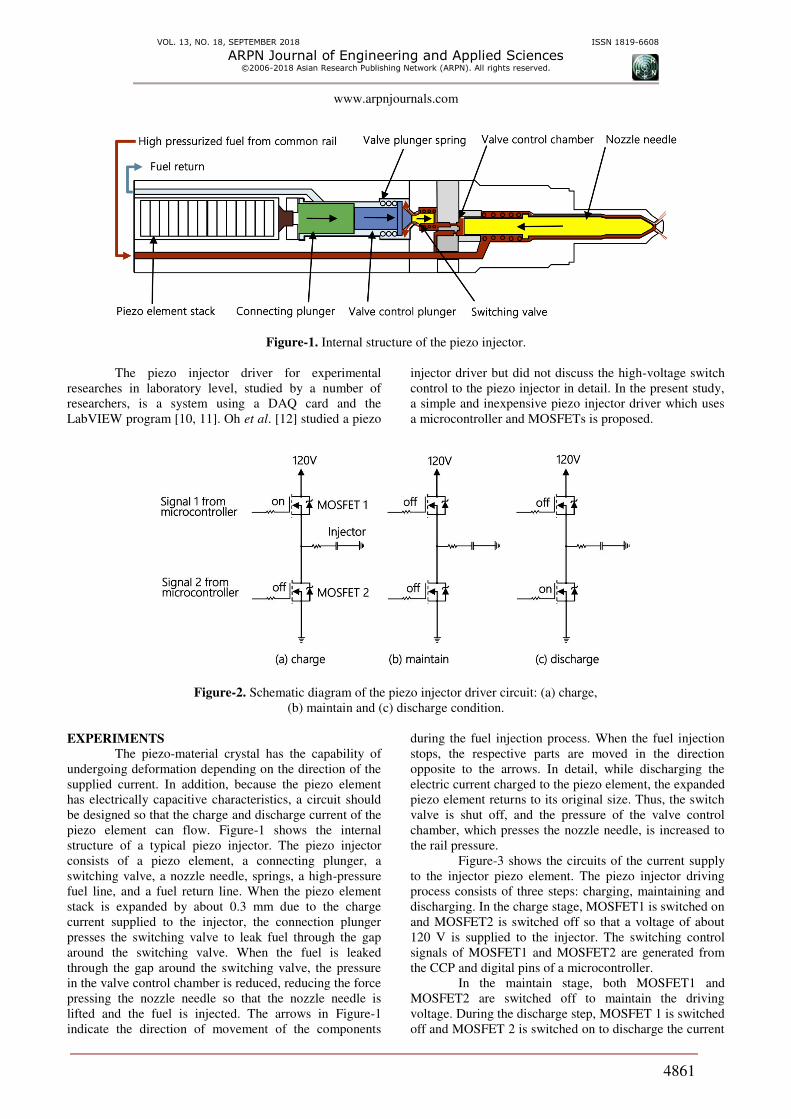
Figure-1. Internal structure of the piezo injector.
The piezo injector driver for experimental
researches in laboratory level, studied by a number of
researchers, is a system using a DAQ card and the
LabVIEW program [10, 11]. Oh et al. [12] studied a piezo
injector driver but did not discuss the high-voltage switch
control to the piezo injector in detail. In the present study,
a simple and inexpensive piezo injector driver which uses
a microcontroller and MOSFETs is proposed.
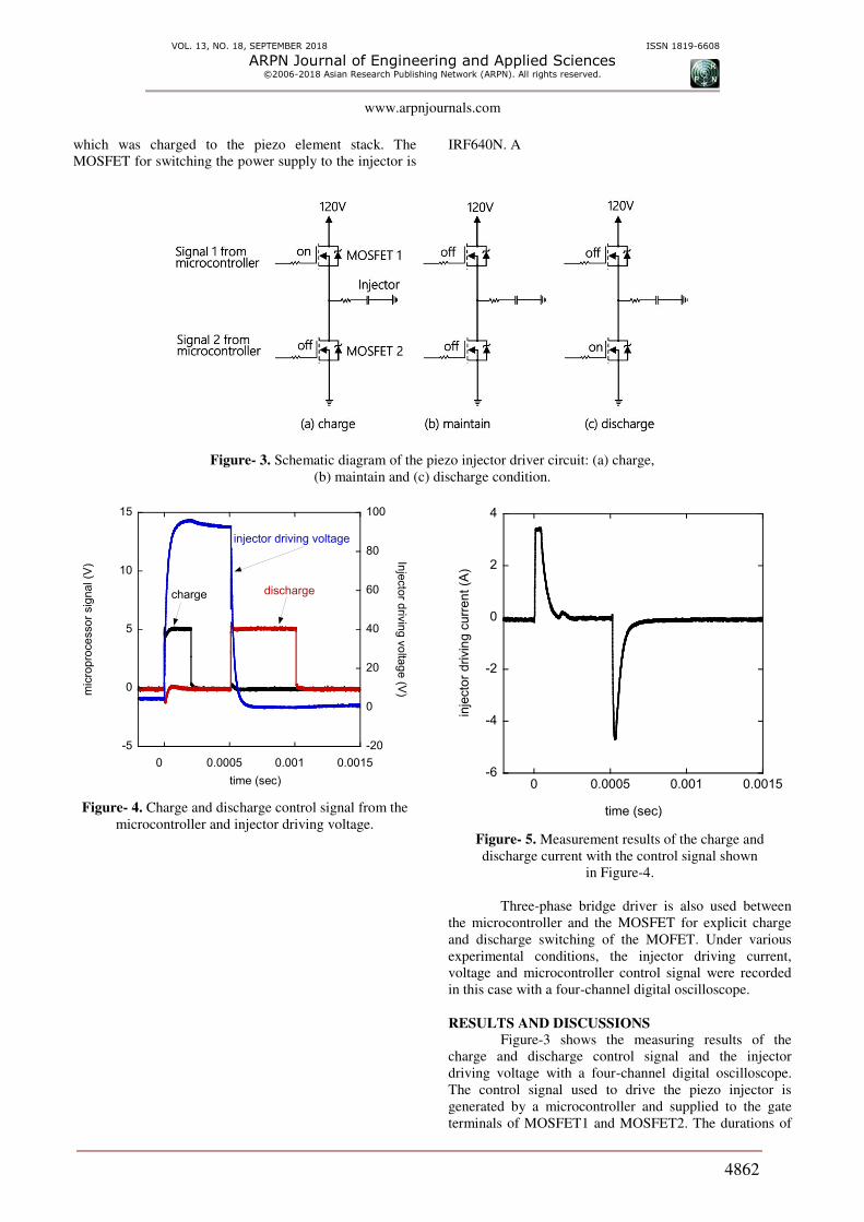
Figure-2. Schematic diagram of the piezo injector driver circuit: (a) charge,
(b) maintain and (c) discharge condition.
EXPERIMENTS
The piezo-material crystal has the capability of
undergoing deformation depending on the direction of the
supplied current. In addition, because the piezo element
has electrically capacitive characteristics, a circuit should
be designed so that the charge and discharge current of the
piezo element can flow. Figure-1 shows the internal
structure of a typical piezo injector. The piezo injector
consists of a piezo element, a connecting plunger, a
switching valve, a nozzle needle, springs, a high-pressure
fuel line, and a fuel return line. When the piezo element
stack is expanded by about 0.3 mm due to the charge
current supplied to the injector, the connection plunger
presses the switching valve to leak fuel through the gap
around the switching valve. When the fuel is leaked
through the gap around the switching valve, the pressure
in the valve control chamber is reduced, reducing the force
pressing the nozzle needle so that the nozzle needle is
lifted and the fuel is injected. The arrows in Figure-1
indicate the direction of movement of the components
during the fuel injection process. When the fuel injection
stops, the respective parts are moved in the direction
opposite to the arrows. In detail, while discharging the
electric current charged to the piezo element, the expanded
piezo element returns to its original size. Thus, the switch
valve is shut off, and the pressure of the valve control
chamber, which presses the nozzle needle, is increased to
the rail pressure.
Figure-3 shows the circuits of the current supply
to the injector piezo element. The piezo injector driving
process consists of three steps: charging, maintaining and
discharging. In the charge stage, MOSFET1 is switched on
and MOSFET2 is switched off so that a voltage of about
120 V is supplied to the injector. The switching control
signals of MOSFET1 and MOSFET2 are generated from
the CCP and digital pins of a microcontroller.
In the maintain stage, both MOSFET1 and
MOSFET2 are switched off to maintain the driving
voltage. During the discharge step, MOSFET 1 is switched
off and MOSFET 2 is switched on to discharge the current
VOL. 13, NO. 18, SEPTEMBER 2018 ISSN 1819-6608
ARPN Journal of Engineering and Applied Sciences ©2006-2018 Asian Research Publishing Network (ARPN). All rights reserved.
www.arpnjournals.com
4862
which was charged to the piezo element stack. The
MOSFET for switching the power supply to the injector is
IRF640N. A
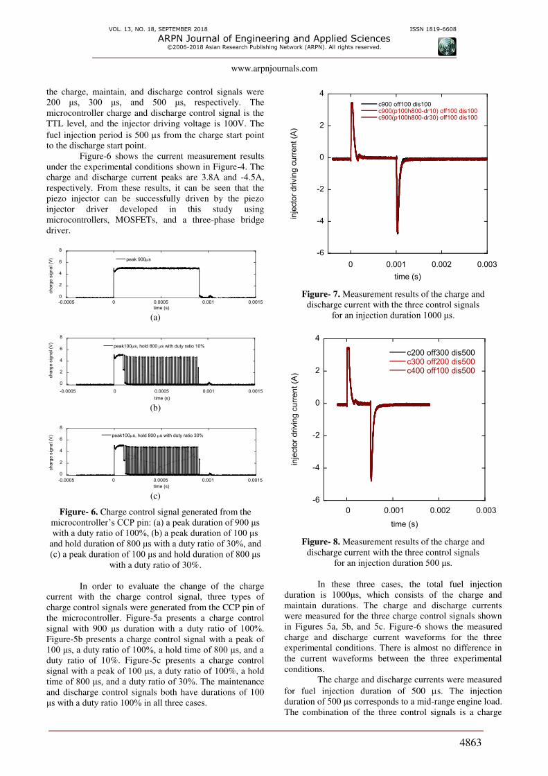
Figure- 3. Schematic diagram of the piezo injector driver circuit: (a) charge,
(b) maintain and (c) discharge condition.
-5
0
5
10
15
-20
0
20
40
60
80
100
0 0.0005 0.001 0.0015
mic
ropro
ce
sso
r sig
na
l (V
)
Inje
cto
r driv
ing v
olta
ge
(V)
time (sec)
charge discharge
injector driving voltage
Figure- 4. Charge and discharge control signal from the
microcontroller and injector driving voltage.
-6
-4
-2
0
2
4
0 0.0005 0.001 0.0015
inje
cto
r drivin
g c
urr
en
t (A
)
time (sec)
Figure- 5. Measurement results of the charge and
discharge current with the control signal shown
in Figure-4.
Three-phase bridge driver is also used between
the microcontroller and the MOSFET for explicit charge
and discharge switching of the MOFET. Under various
experimental conditions, the injector driving current,
voltage and microcontroller control signal were recorded
in this case with a four-channel digital oscilloscope.
RESULTS AND DISCUSSIONS
Figure-3 shows the measuring results of the
charge and discharge control signal and the injector
driving voltage with a four-channel digital oscilloscope.
The control signal used to drive the piezo injector is
generated by a microcontroller and supplied to the gate
terminals of MOSFET1 and MOSFET2. The durations of
VOL. 13, NO. 18, SEPTEMBER 2018 ISSN 1819-6608
ARPN Journal of Engineering and Applied Sciences ©2006-2018 Asian Research Publishing Network (ARPN). All rights reserved.
www.arpnjournals.com
4863
the charge, maintain, and discharge control signals were
200 μs, 300 μs, and 500 μs, respectively. The microcontroller charge and discharge control signal is the
TTL level, and the injector driving voltage is 100V. The
fuel injection period is 500 s from the charge start point
to the discharge start point.
Figure-6 shows the current measurement results
under the experimental conditions shown in Figure-4. The
charge and discharge current peaks are 3.8A and -4.5A,
respectively. From these results, it can be seen that the
piezo injector can be successfully driven by the piezo
injector driver developed in this study using
microcontrollers, MOSFETs, and a three-phase bridge
driver.
0
2
4
6
8
-0.0005 0 0.0005 0.001 0.0015
peak 900s
ch
arg
e s
igna
l (V
)
time (s) (a)
0
2
4
6
8
-0.0005 0 0.0005 0.001 0.0015
peak100s, hold 800 s with duty ratio 10%
ch
arg
e s
ign
al (V
)
time (s) (b)
0
2
4
6
8
-0.0005 0 0.0005 0.001 0.0015
peak100s, hold 800 s with duty ratio 30%
ch
arg
e s
ign
al (V
)
time (s) (c)
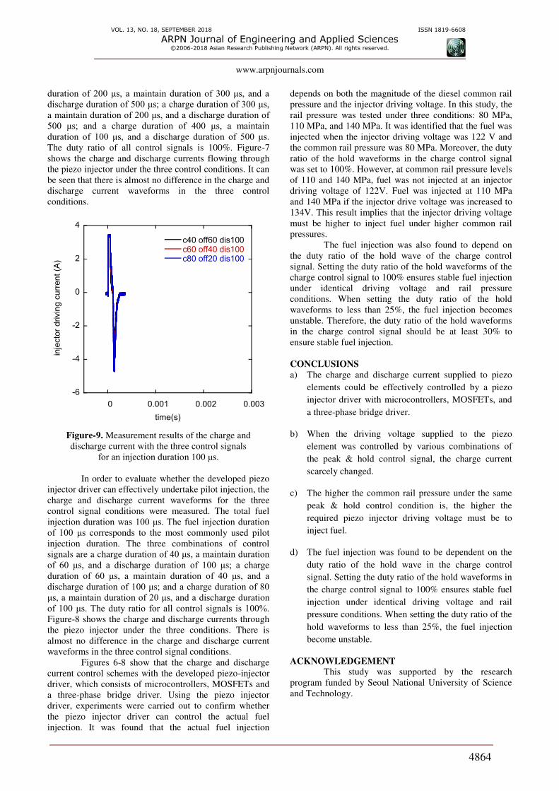
Figure- 6. Charge control signal generated from the
microcontroller’s CCP pin: (a) a peak duration of 900 μs with a duty ratio of 100%, (b) a peak duration of 100 μs
and hold duration of 800 μs with a duty ratio of 30%, and (c) a peak duration of 100 μs and hold duration of 800 μs
with a duty ratio of 30%.
In order to evaluate the change of the charge
current with the charge control signal, three types of
charge control signals were generated from the CCP pin of
the microcontroller. Figure-5a presents a charge control
signal with 900 μs duration with a duty ratio of 100%. Figure-5b presents a charge control signal with a peak of
100 μs, a duty ratio of 100%, a hold time of 800 μs, and a duty ratio of 10%. Figure-5c presents a charge control
signal with a peak of 100 μs, a duty ratio of 100%, a hold
time of 800 μs, and a duty ratio of 30%. The maintenance
and discharge control signals both have durations of 100
μs with a duty ratio 100% in all three cases.
-6
-4
-2
0
2
4
0 0.001 0.002 0.003
c900 off100 dis100c900(p100h800-dr10) off100 dis100c900(p100h800-dr30) off100 dis100
inje
cto
r d
rivin
g c
urr
en
t (A
)
time (s)
Figure- 7. Measurement results of the charge and
discharge current with the three control signals
for an injection duration 1000 μs.
-6
-4
-2
0
2
4
0 0.001 0.002 0.003
c200 off300 dis500c300 off200 dis500c400 off100 dis500
inje
cto
r drivin
g c
urr
en
t (A
)
time (s)
Figure- 8. Measurement results of the charge and
discharge current with the three control signals
for an injection duration 500 μs.
In these three cases, the total fuel injection
duration is 1000μs, which consists of the charge and maintain durations. The charge and discharge currents
were measured for the three charge control signals shown
in Figures 5a, 5b, and 5c. Figure-6 shows the measured
charge and discharge current waveforms for the three
experimental conditions. There is almost no difference in
the current waveforms between the three experimental
conditions.
The charge and discharge currents were measured
for fuel injection duration of 500 s. The injection
duration of 500 μs corresponds to a mid-range engine load.
The combination of the three control signals is a charge
VOL. 13, NO. 18, SEPTEMBER 2018 ISSN 1819-6608
ARPN Journal of Engineering and Applied Sciences ©2006-2018 Asian Research Publishing Network (ARPN). All rights reserved.
www.arpnjournals.com
4864
duration of 200 μs, a maintain duration of 300 μs, and a discharge duration of 500 μs; a charge duration of 300 μs, a maintain duration of 200 μs, and a discharge duration of 500 μs; and a charge duration of 400 μs, a maintain duration of 100 μs, and a discharge duration of 500 μs. The duty ratio of all control signals is 100%. Figure-7
shows the charge and discharge currents flowing through
the piezo injector under the three control conditions. It can
be seen that there is almost no difference in the charge and
discharge current waveforms in the three control
conditions.
-6
-4
-2
0
2
4
0 0.001 0.002 0.003
c40 off60 dis100c60 off40 dis100c80 off20 dis100
inje
cto
r drivin
g c
urr
en
t (A
)
time(s)
Figure-9. Measurement results of the charge and
discharge current with the three control signals
for an injection duration 100 μs.
In order to evaluate whether the developed piezo
injector driver can effectively undertake pilot injection, the
charge and discharge current waveforms for the three
control signal conditions were measured. The total fuel
injection duration was 100 μs. The fuel injection duration of 100 μs corresponds to the most commonly used pilot injection duration. The three combinations of control
signals are a charge duration of 40 μs, a maintain duration of 60 μs, and a discharge duration of 100 μs; a charge duration of 60 μs, a maintain duration of 40 μs, and a discharge duration of 100 μs; and a charge duration of 80 μs, a maintain duration of 20 μs, and a discharge duration
of 100 μs. The duty ratio for all control signals is 100%. Figure-8 shows the charge and discharge currents through
the piezo injector under the three conditions. There is
almost no difference in the charge and discharge current
waveforms in the three control signal conditions.
Figures 6-8 show that the charge and discharge
current control schemes with the developed piezo-injector
driver, which consists of microcontrollers, MOSFETs and
a three-phase bridge driver. Using the piezo injector
driver, experiments were carried out to confirm whether
the piezo injector driver can control the actual fuel
injection. It was found that the actual fuel injection
depends on both the magnitude of the diesel common rail
pressure and the injector driving voltage. In this study, the
rail pressure was tested under three conditions: 80 MPa,
110 MPa, and 140 MPa. It was identified that the fuel was
injected when the injector driving voltage was 122 V and
the common rail pressure was 80 MPa. Moreover, the duty
ratio of the hold waveforms in the charge control signal
was set to 100%. However, at common rail pressure levels
of 110 and 140 MPa, fuel was not injected at an injector
driving voltage of 122V. Fuel was injected at 110 MPa
and 140 MPa if the injector drive voltage was increased to
134V. This result implies that the injector driving voltage
must be higher to inject fuel under higher common rail
pressures.
The fuel injection was also found to depend on
the duty ratio of the hold wave of the charge control
signal. Setting the duty ratio of the hold waveforms of the
charge control signal to 100% ensures stable fuel injection
under identical driving voltage and rail pressure
conditions. When setting the duty ratio of the hold
waveforms to less than 25%, the fuel injection becomes
unstable. Therefore, the duty ratio of the hold waveforms
in the charge control signal should be at least 30% to
ensure stable fuel injection.
CONCLUSIONS
a) The charge and discharge current supplied to piezo
elements could be effectively controlled by a piezo
injector driver with microcontrollers, MOSFETs, and
a three-phase bridge driver.
b) When the driving voltage supplied to the piezo
element was controlled by various combinations of
the peak & hold control signal, the charge current
scarcely changed.
c) The higher the common rail pressure under the same
peak & hold control condition is, the higher the
required piezo injector driving voltage must be to
inject fuel.
d) The fuel injection was found to be dependent on the
duty ratio of the hold wave in the charge control
signal. Setting the duty ratio of the hold waveforms in
the charge control signal to 100% ensures stable fuel
injection under identical driving voltage and rail
pressure conditions. When setting the duty ratio of the
hold waveforms to less than 25%, the fuel injection
become unstable.
ACKNOWLEDGEMENT
This study was supported by the research
program funded by Seoul National University of Science
and Technology.
VOL. 13, NO. 18, SEPTEMBER 2018 ISSN 1819-6608
ARPN Journal of Engineering and Applied Sciences ©2006-2018 Asian Research Publishing Network (ARPN). All rights reserved.
www.arpnjournals.com
4865
REFERENCES
[1] Donald W. Stanton. 2013. Systematic Development of
Highly Efficient and Clean Engines to Meet Future
Commercial Vehicle Greenhouse Gas Regulations.
SAE Paper No. 2013-01-2421.
[2] Manuel A. Gonzalez D and Davide Di Nunno. 2016.
Internal Exhaust Gas Recirculation for Efficiency and
Emissions in a 4-Cylinder Diesel Engine. SAE Paper
No. 2016-01-2184.
[3] Katsanos C.O., Hountalas D.T., Zannis T.C. and
Yfantis E.A. 2010. Potentiality for Optimizing
Operational Performance and Thermal Management
of Diesel Truck Engine Rankine Cycle by Recovering
Heat in EGR Cooler. SAE paper No. 2010-01-0315.
[4] D'Ambrosio S., Ferrari A. and Spessa E., Magro L.
and Vassallo A.2013. Impact on Performance,
Emissions and Thermal Behavior of a New Integrated
Exhaust Manifold Cylinder Head Euro 6 Diesel
Engine. SAE Paper No. 2013-24-0128.
[5] Bosch GmbH. 1996. Governors for Diesel in-line fuel
injection pumps. Technical Instruction. Edition 95/96.
[6] Bosch GmbH. 1994. Diesel distributor fuel injection
pumps. Technical Instruction. Edition 94/95.
[7] Bosch GmbH.2005. Diesel engine management.4th
edition, Bentley Publishers.
[8] Kim J. G. and Lee C. H. Lee. 2016. An experimental
study of the driving of a solenoid type diesel common
rail injector using microprocessors. International
Journal of Engineering and Technology. 8(5): 2346-
2354.
[9] http://europe.autonews.com/article/20061113/ANE/61
109031/injector-wars:-piezo-vs.-solenoid
[10] http://www.ni.com/pdf/manuals/DI_Driver_UM_Rev
F.pdf
[11] Goldwine G. 2008. The Effect of Fuel Injection
Profile on Diesel Engine Performance. PhD. Thesis.
Ben-Gurion University of the Negev.
[12] Oh B.G., Oh S.S., Lee K. Y. and Sunwoo M. H. 2007.
Development of an Injector Driver for Piezo Actuated
Common Rail Injectors. SAE paper No. 2007-01-
3537.


![Untitled-2 [3.imimg.com]3.imimg.com/data3/XO/OC/MY-1810869/crdi-test-bench.pdfPUMPSINJECTOR & RAIL TESTER WITH PIEZO INJECTOR TESTING. SALIENT FEATURES AC FREQUENCY INVERTOR DRIVE,](https://img.pdfslide.net/doc/110x75/61049a7472ea0c0c58250194/untitled-2-3imimgcom3imimgcomdata3xoocmy-1810869crdi-test-benchpdf-pumpsinjector.jpg)