Embed Size (px)
Citation preview
Communication and Communication and Ground Station Ground Station
12 October 2008
AgendaAgendaComm. Work and Requirements
Beacon TelemetryLink BudgetGeneral DecisionGround Station
Communication Work Communication Work Beacon: Low bit rate device on
the satellite which is functional for the entire lifetime of the satellite.
Telemetry Data: High bit rate (1.2kbps) Monopole for downlink of data.
Ground Station: Which can receive signals
We don’t have UPLINK
Communication Communication RequirementsRequirements
Both the antennas onboard must be transmitting linearly polarized radio signals.
2 independent crossed yagi antennas at ground stations to receive data and measure their polarization.
Low cost ground station for other universities to measure polarization.
AgendaAgendaComm. Work and RequirementsBeacon TelemetryLink BudgetGeneral DecisionGround Station
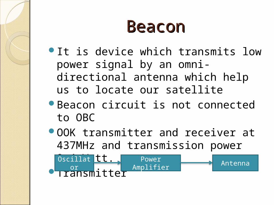
BeaconBeaconIt is device which transmits low power
signal by an omni-directional antenna which help us to locate our satellite
Beacon circuit is not connected to OBC OOK transmitter and receiver at
437MHz and transmission power 0.4 Watt.
TransmitterOscillator
Power Amplifier
Antenna
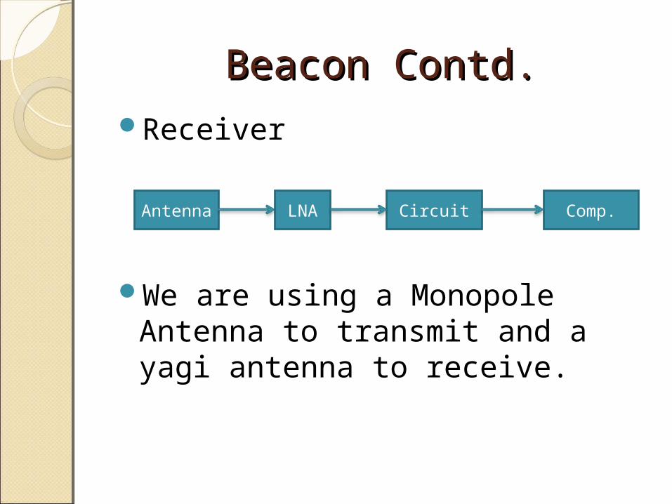
Beacon Contd.Beacon Contd.Receiver
We are using a Monopole Antenna to transmit and a yagi antenna to receive.
Antenna LNA Circuit Comp.
AgendaAgendaComm. Work and RequirementsBeacon TelemetryLink BudgetGeneral DecisionGround Station
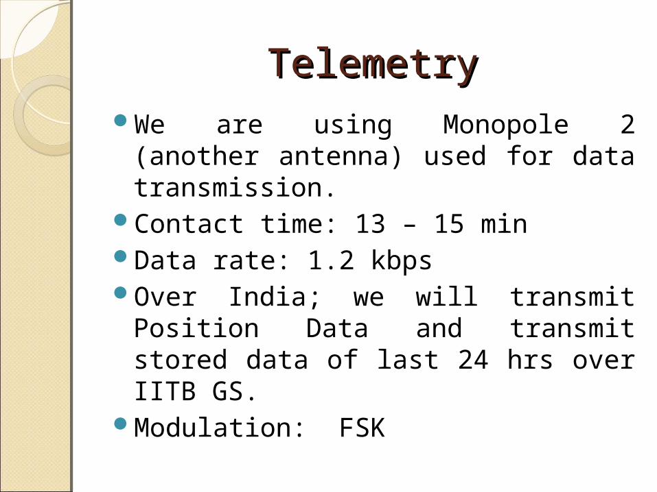
TelemetryTelemetryWe are using Monopole 2
(another antenna) used for data transmission.
Contact time: 13 – 15 minData rate: 1.2 kbpsOver India; we will transmit
Position Data and transmit stored data of last 24 hrs over IITB GS.
Modulation: FSK
AgendaAgendaComm. Work and RequirementsBeacon TelemetryLink BudgetGeneral DecisionGround Station
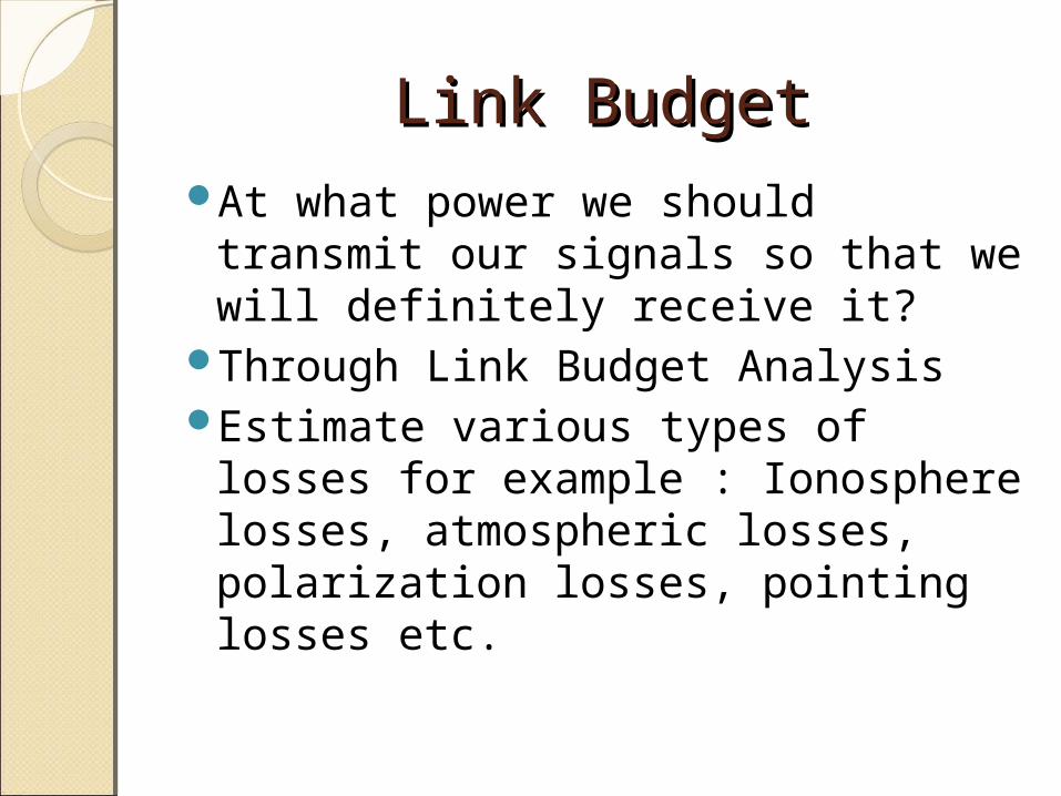
Link BudgetLink BudgetAt what power we should
transmit our signals so that we will definitely receive it?
Through Link Budget AnalysisEstimate various types of losses
for example : Ionosphere losses, atmospheric losses, polarization losses, pointing losses etc.
AgendaAgendaComm. Work and RequirementsBeacon TelemetryLink BudgetGeneral DecisionGround Station
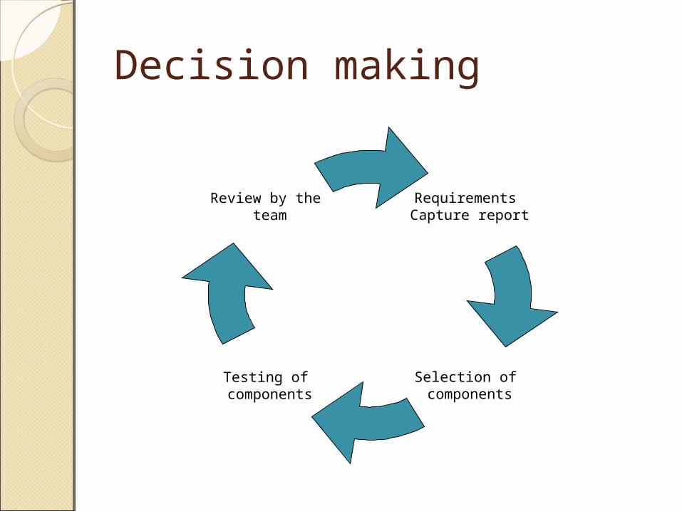
Decision making
Requirements Capture report
Selection of components
Testing of components
Review by the team
Communication parametersModulationCarrier Wave FrequencyOn Board AntennaeTransmitter CircuitProtocol of Transmission
Modulation Technique.The three key parameters of a carrier
wave are its amplitude, it’s phase and it’s frequency all of which can be modified in accordance with a low frequency information signal to obtain the modulated signal.
Modulation Techniques can be broadly divided into 3 categories Analog Modulation and Digital Modulation and Pulse modulation.
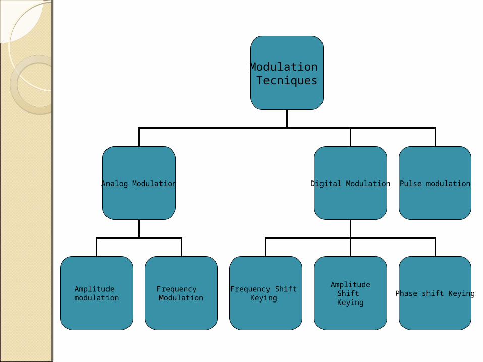
Modulation Tecniques
Analog Modulation Digital Modulation Pulse modulation
Amplitude modulation
Frequency Modulation
Frequency Shift Keying
AmplitudeShift
KeyingPhase shift Keying
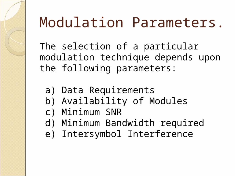
Modulation Parameters.
The selection of a particular modulation technique depends upon the following parameters:
a) Data Requirements b) Availability of Modules c) Minimum SNR d) Minimum Bandwidth required e) Intersymbol Interference

Frequency Shift Keying
We decided to go ahead with frequency shift keying as it has the following characteristics :
a) Spectrally Efficient b) Moderate value of Eb/Noc) Modules Readily Availabled) Low intersymbol interference as
compared to FM.
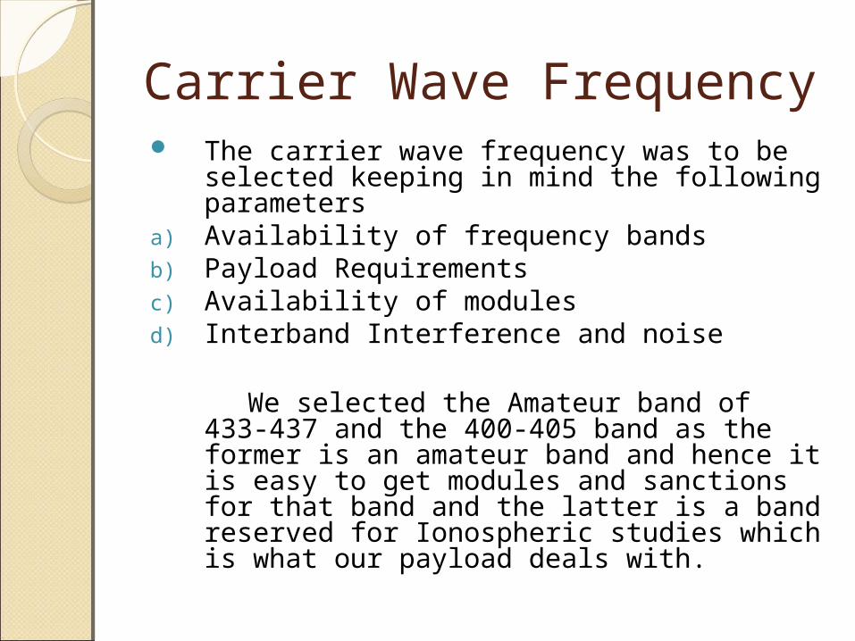
Carrier Wave Frequency The carrier wave frequency was to be
selected keeping in mind the following parameters
a) Availability of frequency bands b) Payload Requirementsc) Availability of modulesd) Interband Interference and noise
We selected the Amateur band of 433-437 and the 400-405 band as the former is an amateur band and hence it is easy to get modules and sanctions for that band and the latter is a band reserved for Ionospheric studies which is what our payload deals with.
Onboard AntennaAn antenna is a transducer designed
to transmit or receive electromagnetic waves.
As we had done away with uplink the selction of the transmitting antennae, both the telemetry and the beacon, was a very critical decision for the team.
Antenna parameters Moderate to High Gain Moderate BeamwidthLinear Polarization For payload
purposesPolarization PurityEase of FabricationCharacteristic length to be of the
order of satellite dimensions.
Monopole Antennae We chose the monopole over the
other antennae because:a) Being Omnidirectional it reduces the
constraints on attitude controlb) It produces a linearly polarized beam.c) High polarization purity can be obtained by
careful design of the antenna.d) The length of the antenna is comparable to
the satellite dimensionse) It is easy to fabricate .f) The loss in gain can be compensated by
using a directional antenna on the ground station
Transmitter Circuit Parameters.Industrial grade .Low power requirements in
accordance with the power budget.
Wide bandwidth covering our operational range.
Minimum and Maximum Bitrate should cover our requirements
Compatible with AX.25 protocol.
CC1020
We selected this circuit mainly because it had been used earlier in a student satellite and hence had some space heritage. The other parameters of CC1020 are
a) It is industrial grade.b) It is operational over a frequency band of
405MHz to 470 MHz and is tunable.c) It’s power requirements are low.d) It supports packet data transmission.e) Maximum bitrate is 156.2 kBps which is
much higher than our requirements.
Protocol • It is a standard practice in
communication systems to use a protocol for the transmission of data.
• The protocol tells the user regarding the start and end of the data stream and enables the end user to correct the data in case it has become corrupt due to noise or interference.
AX.25
The AX.25 protocol is a standard protocol used by the amateur radio enthusiasts and is robust enough for our purpose.
Ground station Requirements The ground station equipment
can be divided into the following :a)Pre-pass Componentsb)Real Time Componentsc)Post-pass Components
Pre pass Components• Nova Tracking Software We have selected this software
as it is compatible with the rotor interface.
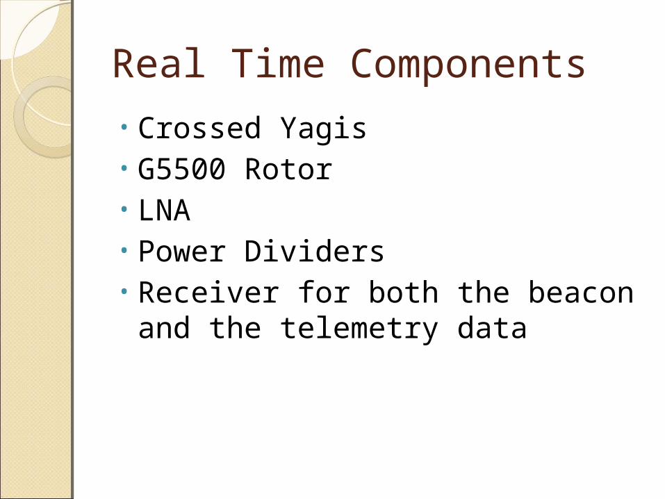
Real Time Components• Crossed Yagis • G5500 Rotor• LNA • Power Dividers• Receiver for both the beacon and
the telemetry data
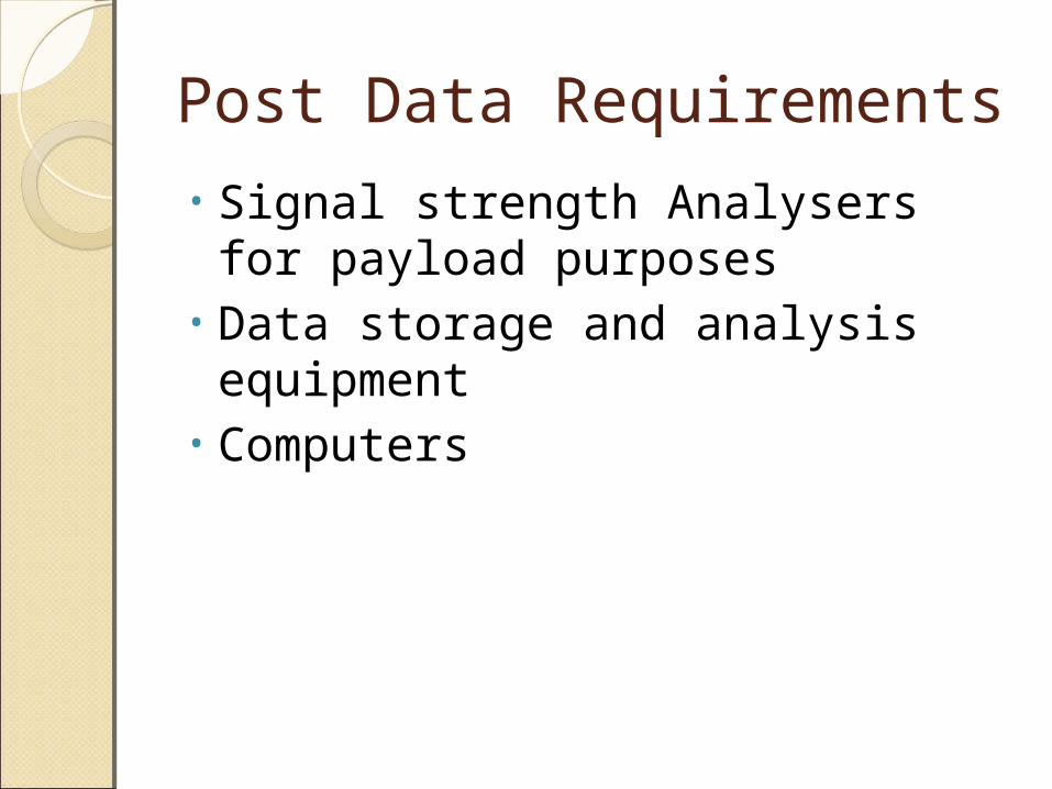
Post Data Requirements• Signal strength Analysers for
payload purposes• Data storage and analysis
equipment• Computers
AgendaAgendaComm. Work and RequirementsBeacon TelemetryLink BudgetGeneral DecisionGround Station
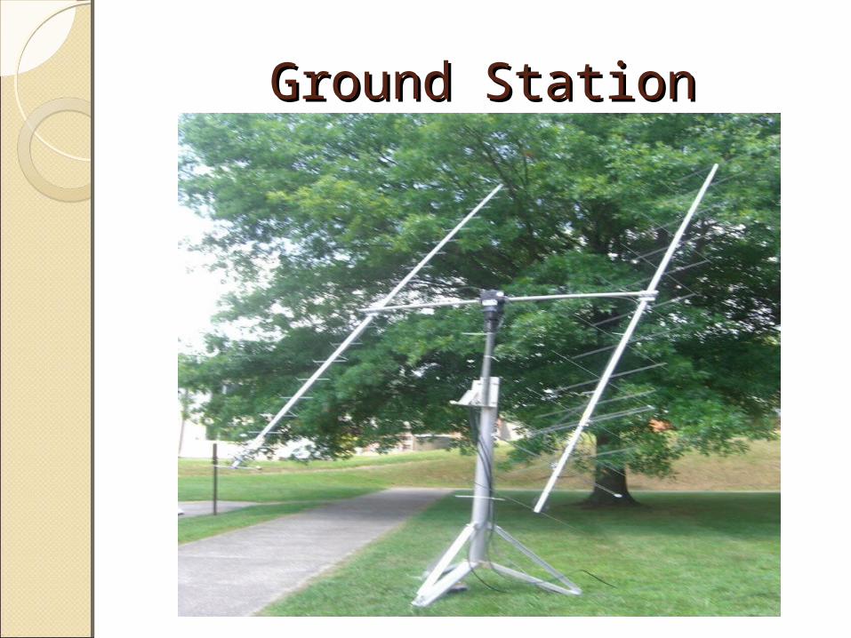
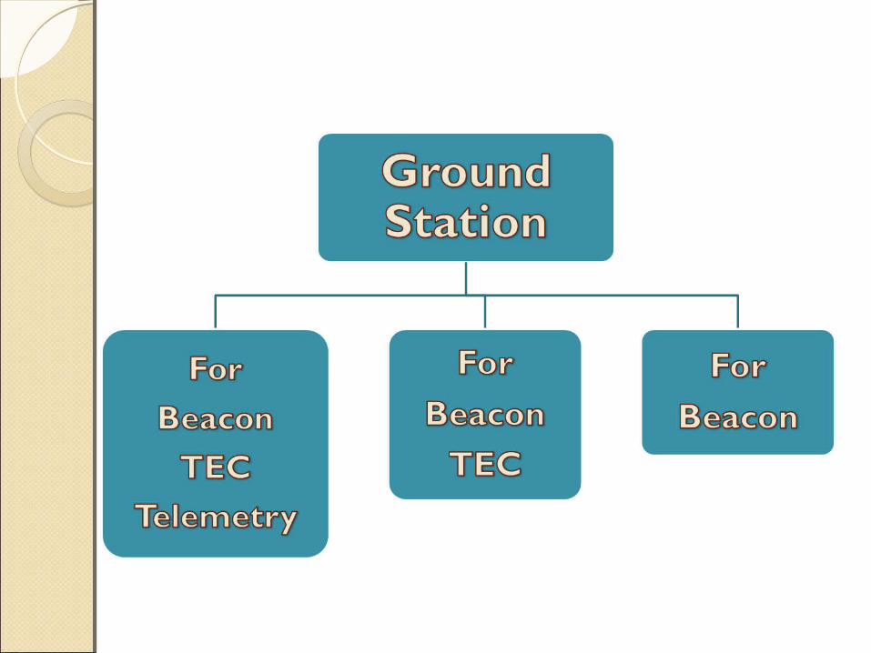
Ground StationGround Station
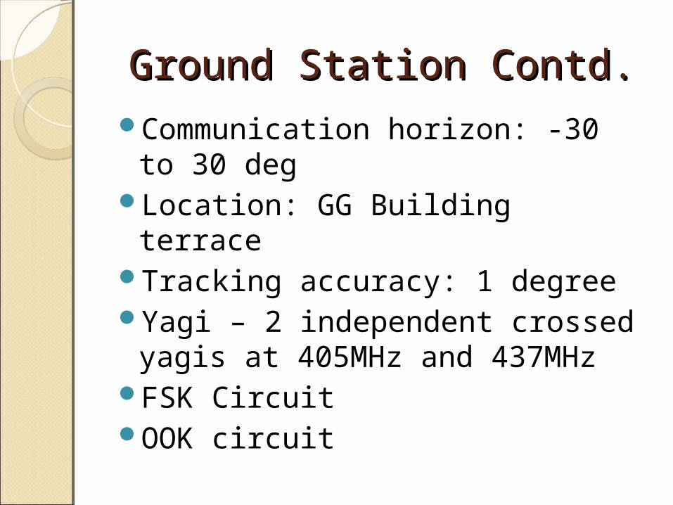
Ground Station Contd.Ground Station Contd.Communication horizon: -30 to
30 degLocation: GG Building terraceTracking accuracy: 1 degree Yagi – 2 independent crossed
yagis at 405MHz and 437MHz FSK CircuitOOK circuit
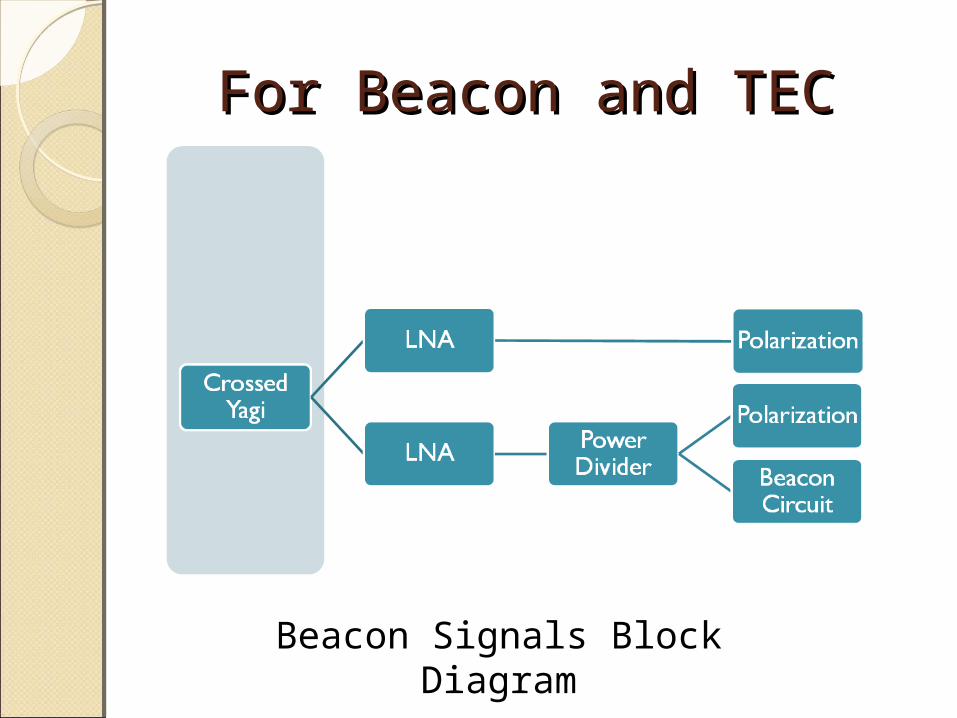
For Beacon and TEC For Beacon and TEC
Beacon Signals Block Diagram
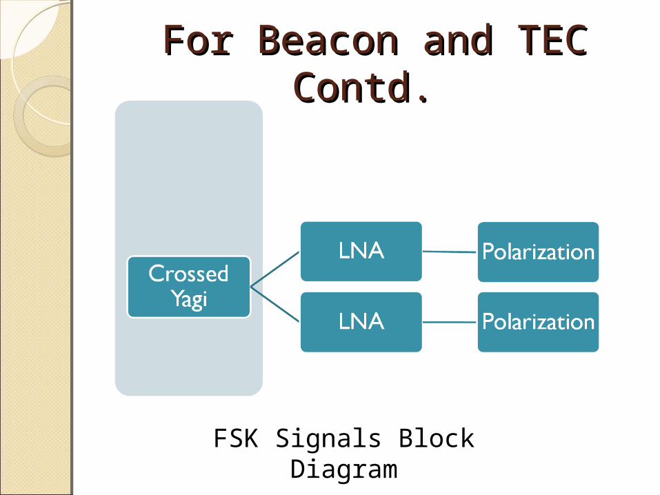
For Beacon and TEC For Beacon and TEC Contd. Contd.
FSK Signals Block Diagram
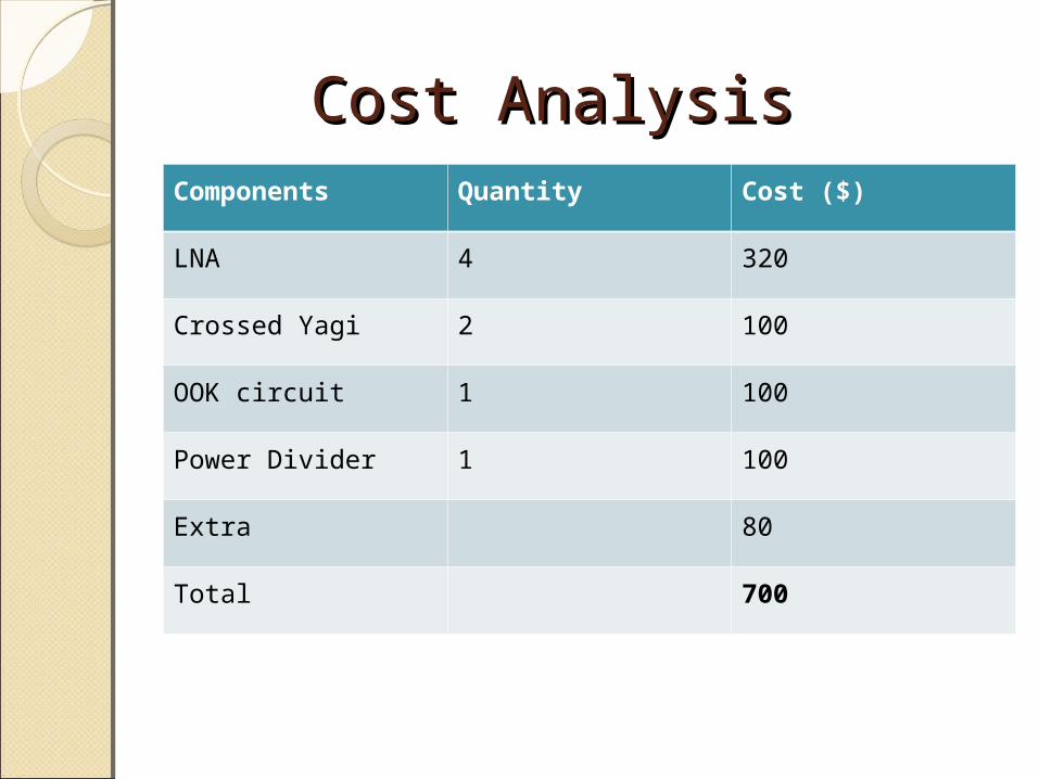
Cost Analysis Cost Analysis Components Quantity Cost ($)
LNA 4 320
Crossed Yagi 2 100
OOK circuit 1 100
Power Divider 1 100
Extra 80
Total 700
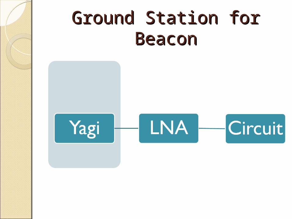
Ground Station for BeaconGround Station for Beacon
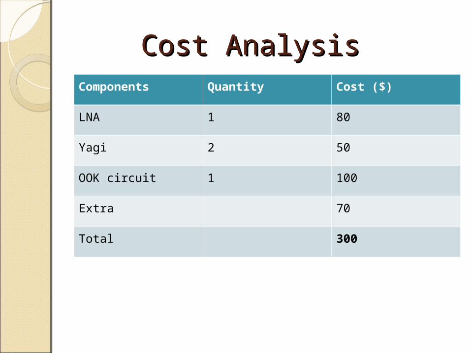
Cost Analysis Cost Analysis Components Quantity Cost ($)
LNA 1 80
Yagi 2 50
OOK circuit 1 100
Extra 70
Total 300

Thank YouThank You