Embed Size (px)
Citation preview
Installation Instructions
Compact 1769-OF8C Analog Output Module
Inside
Module Description ..................................................................................2
Module Installation...................................................................................3
System Assembly......................................................................................4
Mounting Expansion I/O ...........................................................................5
Replacing a Single Module within a System ...........................................7
Module Spare/Replacement Parts ...........................................................8
Field Wiring Connections..........................................................................8
I/O Memory Mapping .............................................................................12
Specifications .........................................................................................23
Hazardous Location Considerations .......................................................26
Environnements dangereux ....................................................................27
For More Information ..............................................................................28
Publication 1769-IN065B-EN-P - September 2005
2 Compact 1769-OF8C Analog Output Module
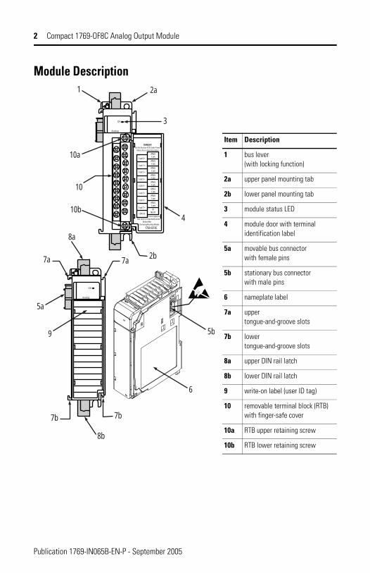
Module Description
Item Description
1 bus lever (with locking function)
2a upper panel mounting tab
2b lower panel mounting tab
3 module status LED
4 module door with terminal identification label
5a movable bus connector with female pins
5b stationary bus connector with male pins
6 nameplate label
7a upper tongue-and-groove slots
7b lower tongue-and-groove slots
8a upper DIN rail latch
8b lower DIN rail latch
9 write-on label (user ID tag)
10 removable terminal block (RTB) with finger-safe cover
10a RTB upper retaining screw
10b RTB lower retaining screw
10a
10b4
10
2b
3
2a1
5a
9 5b
6
7a
7b
8b
7b
8a
7a
1769-OF8C
DANGERDo Not Remove RTB Under Power
Unless Area is Non-Hazardous
Ensure AdjacentBus Lever is Unlatched/Latched Before/After Removing/Inserting Module
dcNEUT
I out 2 +
I out 3 +
I out 4 +
I out 5 +
I out 6 +
I out 7 +
+24V dc
I out 1 +
I out 0 +
ANGLCom
ANLGCom
ANLGCom
ANLGCom
ANLGCom
ANLGCom
ANLGCom
ANLGCom
OK
Analog
OK
Analog
Publication 1769-IN065B-EN-P - September 2005
Compact 1769-OF8C Analog Output Module 3
Module InstallationCompact I/O is suitable for use in an industrial environment when installed in accordance with these instructions. Specifically, this equipment is intended for use
in clean, dry environments (Pollution degree 2(1)) and to circuits not exceeding
Over Voltage Category II(2) (IEC 60664-1).(3)
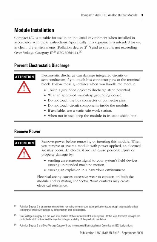
Prevent Electrostatic Discharge
Remove Power
(1) Pollution Degree 2 is an environment where, normally, only non-conductive pollution occurs except that occasionally a temporary conductivity caused by condensation shall be expected.
(2) Over Voltage Category II is the load level section of the electrical distribution system. At this level transient voltages are controlled and do not exceed the impulse voltage capability of the product’s insulation.
(3) Pollution Degree 2 and Over Voltage Category II are International Electrotechnical Commission (IEC) designations.
ATTENTION Electrostatic discharge can damage integrated circuits or semiconductors if you touch bus connector pins or the terminal block. Follow these guidelines when you handle the module:
• Touch a grounded object to discharge static potential.
• Wear an approved wrist-strap grounding device.
• Do not touch the bus connector or connector pins.
• Do not touch circuit components inside the module.
• If available, use a static-safe work station.
• When not in use, keep the module in its static-shield box.
ATTENTION Remove power before removing or inserting this module. When you remove or insert a module with power applied, an electrical arc may occur. An electrical arc can cause personal injury or property damage by:
• sending an erroneous signal to your system’s field devices, causing unintended machine motion
• causing an explosion in a hazardous environment
Electrical arcing causes excessive wear to contacts on both the module and its mating connector. Worn contacts may create electrical resistance.
Publication 1769-IN065B-EN-P - September 2005
4 Compact 1769-OF8C Analog Output Module
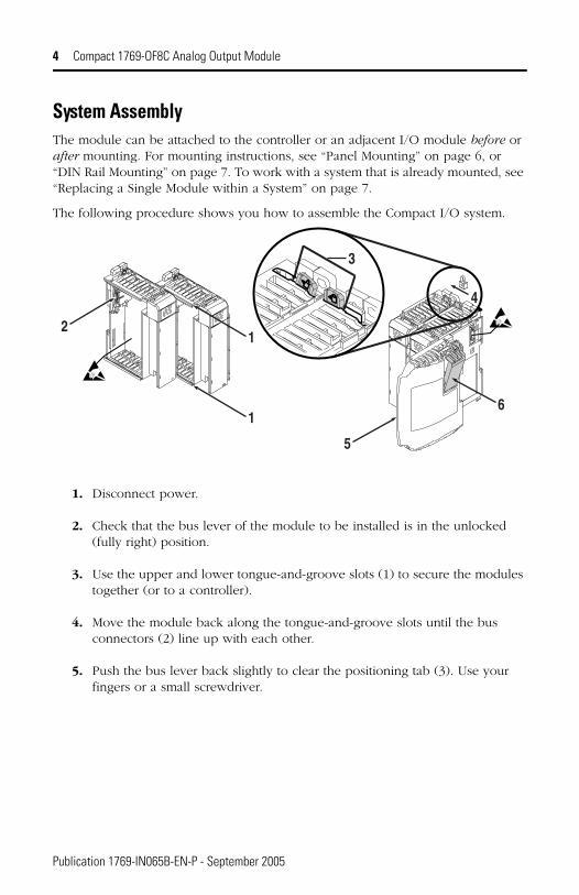
System AssemblyThe module can be attached to the controller or an adjacent I/O module before or after mounting. For mounting instructions, see “Panel Mounting” on page 6, or “DIN Rail Mounting” on page 7. To work with a system that is already mounted, see “Replacing a Single Module within a System” on page 7.
The following procedure shows you how to assemble the Compact I/O system.
1. Disconnect power.
2. Check that the bus lever of the module to be installed is in the unlocked (fully right) position.
3. Use the upper and lower tongue-and-groove slots (1) to secure the modules together (or to a controller).
4. Move the module back along the tongue-and-groove slots until the bus connectors (2) line up with each other.
5. Push the bus lever back slightly to clear the positioning tab (3). Use your fingers or a small screwdriver.
6
5
4
3
1
12
Publication 1769-IN065B-EN-P - September 2005

Compact 1769-OF8C Analog Output Module 5
6. To allow communication between the controller and module, move the bus lever fully to the left (4) until it clicks. Ensure it is locked firmly in place.
7. Attach an end cap terminator (5) to the last module in the system by using the tongue-and-groove slots as before.
8. Lock the end cap bus terminator (6).
Mounting Expansion I/O
Minimum Spacing
Maintain spacing from enclosure walls, wireways, adjacent equipment, etc. Allow 50 mm (2 in.) of space on all sides for adequate ventilation, as shown:
ATTENTION When attaching I/O modules, it is very important that the bus connectors are securely locked together to ensure proper electrical connection.
IMPORTANT A 1769-ECR or 1769-ECL right or left end cap must be used to terminate the end of the serial communication bus.
ATTENTION During panel or DIN rail mounting of all devices, be sure that all debris (metal chips, wire strands, etc.) is kept from falling into the module. Debris that falls into the module could cause damage on power up.
Top
Bottom
Side SideHost Controller
Com
pact
I/O
Com
pact
I/O
Com
pact
I/O
Com
pact
I/O
Com
pact
I/O
End
Cap
Publication 1769-IN065B-EN-P - September 2005
6 Compact 1769-OF8C Analog Output Module
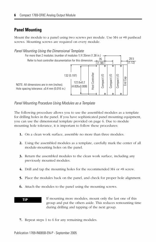
Panel MountingMount the module to a panel using two screws per module. Use M4 or #8 panhead screws. Mounting screws are required on every module.
Panel Mounting Using the Dimensional Template
Panel Mounting Procedure Using Modules as a Template
The following procedure allows you to use the assembled modules as a template for drilling holes in the panel. If you have sophisticated panel mounting equipment, you can use the dimensional template provided on page 6. Due to module mounting hole tolerance, it is important to follow these procedures:
1. On a clean work surface, assemble no more than three modules.
2. Using the assembled modules as a template, carefully mark the center of all module-mounting holes on the panel.
3. Return the assembled modules to the clean work surface, including any previously mounted modules.
4. Drill and tap the mounting holes for the recommended M4 or #8 screw.
5. Place the modules back on the panel, and check for proper hole alignment.
6. Attach the modules to the panel using the mounting screws.
7. Repeat steps 1 to 6 for any remaining modules.
TIP If mounting more modules, mount only the last one of this group and put the others aside. This reduces remounting time during drilling and tapping of the next group.
Host
Con
trolle
r
Com
pact
I/O
Com
pact
I/O
Com
pact
I/O
End
Cap132 (5.197)
122.6±0.2(4.826±0.008)
35(1.38)
28.5(1.12)
Refer to host controller documentation for this dimension.
For more than 2 modules: (number of modules-1) X 35mm (1.38 in.)
NOTE: All dimensions are in mm (inches). Hole spacing tolerance: ±0.4 mm (0.016 in.)
Publication 1769-IN065B-EN-P - September 2005
Compact 1769-OF8C Analog Output Module 7
DIN Rail MountingThe module can be mounted using the following DIN rails: 35 x 7.5 mm (EN 50 022 - 35 x 7.5) or 35 x 15 mm (EN 50 022 - 35 x 15).
Before mounting the module on a DIN rail, close the DIN rail latches. Press the DIN rail mounting area of the module against the DIN rail. The latches will momentarily open and lock into place.
Replacing a Single Module within a SystemThe module can be replaced while the system is mounted to a panel (or DIN rail). Follow the steps below in order:
1. Remove power. See important note on page 3.
2. On the module to be removed, remove the upper and lower mounting screws from the module (or open the DIN latches using a flat-blade or phillips-style screwdriver).
3. Move the bus lever to the right to disconnect (unlock) the bus.
4. On the right-side adjacent module, move its bus lever to the right (unlock) to disconnect it from the module to be removed.
5. Gently slide the disconnected module forward. If you feel excessive resistance, check that the module has been disconnected from the bus, and that both mounting screws have been removed (or DIN latches opened).
6. Before installing the replacement module, be sure that the bus lever on the module to be installed, and on the right-side adjacent module are in the unlocked (fully right) position.
7. Slide the replacement module into the open slot.
8. Connect the modules together by locking (fully left) the bus levers on the replacement module and the right-side adjacent module.
9. Replace the mounting screws (or snap the module onto the DIN rail).
TIP It may be necessary to rock the module slightly from front to back to remove it, or, in a panel-mounted system, to loosen the screws of adjacent modules.
Publication 1769-IN065B-EN-P - September 2005
8 Compact 1769-OF8C Analog Output Module
Module Spare/Replacement Parts• Terminal block, catalog number 1769-RTBN12 (1 per kit)
(A-B part number A22112-319-01)
• Door, catalog number 1769-RD (2 per kit)
Field Wiring Connections
Grounding the ModuleThis product is intended to be mounted to a well-grounded mounting surface such as a metal panel. Additional grounding connections from the module’s mounting tabs or DIN rail (if used), are not required unless the mounting surface cannot be grounded. Refer to Industrial Automation Wiring and Grounding Guidelines, Allen-Bradley publication 1770-4.1, for additional information.
System Wiring GuidelinesConsider the following when wiring your system:
• All module commons (ANLG COM) are connected in the analog module. The analog common (ANLG COM) is not connected to earth ground inside the module.
• Channels are not isolated from each other.
• Use Belden 8761, or equivalent, shielded wire.
• Under normal conditions, the drain wire and shield junction must be connected to earth ground, via a panel or DIN rail mounting screw at the analog I/O module end. Keep the shield connection to ground as short as
possible.(1)
• To ensure optimum accuracy, limit overall cable impedance by keeping your cable as short as possible. Locate the I/O system as close to your sensors or actuators as your application will permit.
• Current outputs (Iout 0+ to Iout 7+) of the 1769-OF8C module source current that returns to ANLG COM. Load resistance for a current output channel must remain between 0 and 500 Ω.
(1) In environments where high frequency noise may be present, it may be necessary to ground the shield via a 0.1µF capacitor at the load end and also ground the module end without a capacitor.
Publication 1769-IN065B-EN-P - September 2005
Compact 1769-OF8C Analog Output Module 9
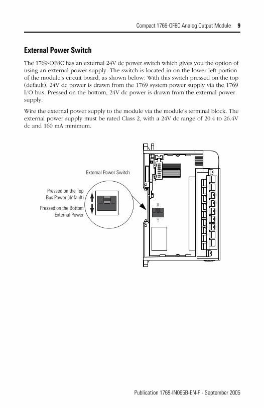
External Power SwitchThe 1769-OF8C has an external 24V dc power switch which gives you the option of using an external power supply. The switch is located in on the lower left portion of the module’s circuit board, as shown below. With this switch pressed on the top (default), 24V dc power is drawn from the 1769 system power supply via the 1769 I/O bus. Pressed on the bottom, 24V dc power is drawn from the external power supply.
Wire the external power supply to the module via the module’s terminal block. The external power supply must be rated Class 2, with a 24V dc range of 20.4 to 26.4V dc and 160 mA minimum.
BUSEXT
External Power Switch
Pressed on the Top Bus Power (default)
Pressed on the Bottom External Power
Publication 1769-IN065B-EN-P - September 2005
10 Compact 1769-OF8C Analog Output Module
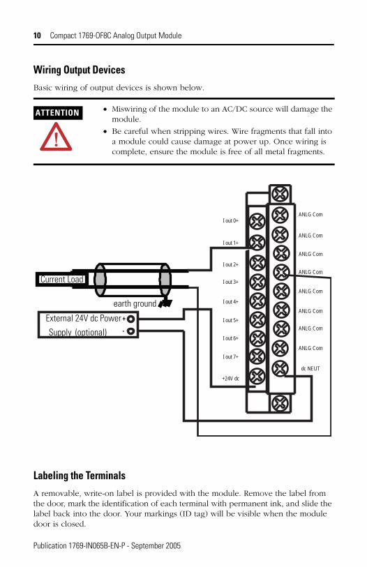
Wiring Output DevicesBasic wiring of output devices is shown below.
Labeling the TerminalsA removable, write-on label is provided with the module. Remove the label from the door, mark the identification of each terminal with permanent ink, and slide the label back into the door. Your markings (ID tag) will be visible when the module door is closed.
ATTENTION • Miswiring of the module to an AC/DC source will damage the module.
• Be careful when stripping wires. Wire fragments that fall into a module could cause damage at power up. Once wiring is complete, ensure the module is free of all metal fragments.
ANLG Com
ANLG Com
ANLG Com
ANLG Com
ANLG Com
ANLG Com
ANLG Com
ANLG Com
dc NEUT
+24V dc
I out 7+
I out 6+
I out 5+
I out 4+
I out 3+
I out 2+
I out 1+
I out 0+
+-
Current Load
earth ground
External 24V dc Power
Supply (optional)
Publication 1769-IN065B-EN-P - September 2005
Compact 1769-OF8C Analog Output Module 11
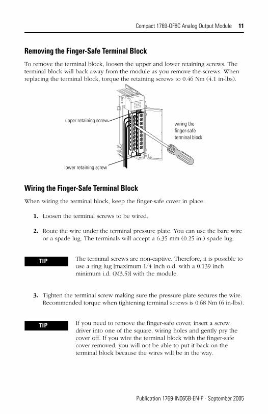
Removing the Finger-Safe Terminal BlockTo remove the terminal block, loosen the upper and lower retaining screws. The terminal block will back away from the module as you remove the screws. When replacing the terminal block, torque the retaining screws to 0.46 Nm (4.1 in-lbs).
Wiring the Finger-Safe Terminal BlockWhen wiring the terminal block, keep the finger-safe cover in place.
1. Loosen the terminal screws to be wired.
2. Route the wire under the terminal pressure plate. You can use the bare wire or a spade lug. The terminals will accept a 6.35 mm (0.25 in.) spade lug.
3. Tighten the terminal screw making sure the pressure plate secures the wire. Recommended torque when tightening terminal screws is 0.68 Nm (6 in-lbs).
TIP The terminal screws are non-captive. Therefore, it is possible to use a ring lug [maximum 1/4 inch o.d. with a 0.139 inch minimum i.d. (M3.5)] with the module.
TIP If you need to remove the finger-safe cover, insert a screw driver into one of the square, wiring holes and gently pry the cover off. If you wire the terminal block with the finger-safe cover removed, you will not be able to put it back on the terminal block because the wires will be in the way.
wiring the finger-safe terminal block
upper retaining screw
lower retaining screw
Publication 1769-IN065B-EN-P - September 2005
12 Compact 1769-OF8C Analog Output Module
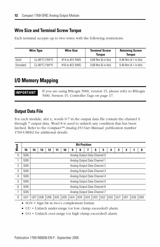
Wire Size and Terminal Screw TorqueEach terminal accepts up to two wires with the following restrictions:
I/O Memory Mapping
Output Data FileFor each module, slot x, words 0-7 in the output data file contain the channel 0 through 7 output data. Word 8 is used to unlatch any condition that has been latched. Refer to the Compact™ Analog I/O User Manual, publication number 1769-UM002 for additional details.
• SGN = Sign bit in two’s complement format.
• UU = Unlatch under-range (or low clamp exceeded) alarm.
• UO = Unlatch over-range (or high clamp exceeded) alarm.
Wire Type Wire Size Terminal Screw Torque
Retaining Screw Torque
Solid Cu-90°C (194°F) #14 to #22 AWG 0.68 Nm (6 in-lbs) 0.46 Nm (4.1 in-lbs)
Stranded Cu-90°C (194°F) #16 to #22 AWG 0.68 Nm (6 in-lbs) 0.46 Nm (4.1 in-lbs)
IMPORTANT If you are using RSLogix 5000, version 15, please refer to RSLogix 5000, Version 15, Controller Tags on page 17.
Wor
d Bit Position
15 14 13 12 11 10 9 8 7 6 5 4 3 2 1 0
0 SGN Analog Output Data Channel 0
1 SGN Analog Output Data Channel 1
2 SGN Analog Output Data Channel 2
3 SGN Analog Output Data Channel 3
4 SGN Analog Output Data Channel 4
5 SGN Analog Output Data Channel 5
6 SGN Analog Output Data Channel 6
7 SGN Analog Output Data Channel 7
8 UU7 UO7 UU6 UO6 UU5 UO5 UU4 UO4 UU3 UO3 UU2 UO2 UU1 UO1 UU0 UO0
Publication 1769-IN065B-EN-P - September 2005
Compact 1769-OF8C Analog Output Module 13
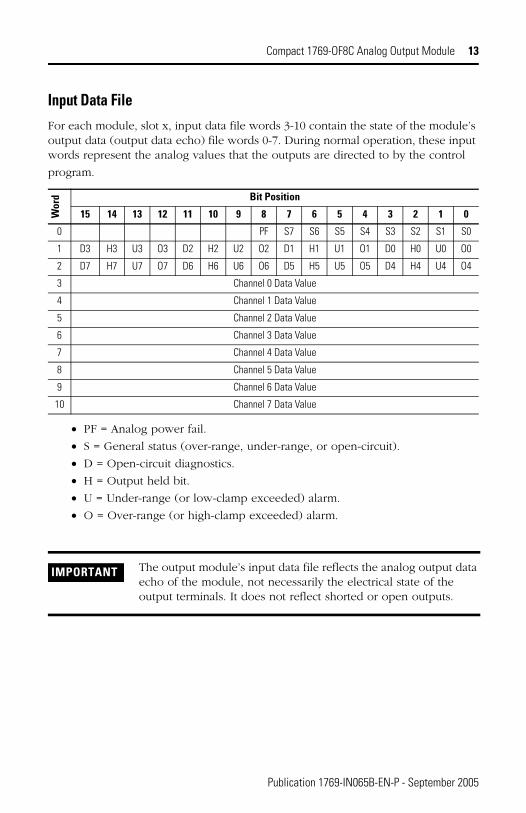
Input Data FileFor each module, slot x, input data file words 3-10 contain the state of the module’s output data (output data echo) file words 0-7. During normal operation, these input words represent the analog values that the outputs are directed to by the control
program.
• PF = Analog power fail.
• S = General status (over-range, under-range, or open-circuit).
• D = Open-circuit diagnostics.
• H = Output held bit.
• U = Under-range (or low-clamp exceeded) alarm.
• O = Over-range (or high-clamp exceeded) alarm.
Wor
d Bit Position
15 14 13 12 11 10 9 8 7 6 5 4 3 2 1 0
0 PF S7 S6 S5 S4 S3 S2 S1 S0
1 D3 H3 U3 O3 D2 H2 U2 O2 D1 H1 U1 O1 D0 H0 U0 O0
2 D7 H7 U7 O7 D6 H6 U6 O6 D5 H5 U5 O5 D4 H4 U4 O4
3 Channel 0 Data Value
4 Channel 1 Data Value
5 Channel 2 Data Value
6 Channel 3 Data Value
7 Channel 4 Data Value
8 Channel 5 Data Value
9 Channel 6 Data Value
10 Channel 7 Data Value
IMPORTANT The output module’s input data file reflects the analog output data echo of the module, not necessarily the electrical state of the output terminals. It does not reflect shorted or open outputs.
Publication 1769-IN065B-EN-P - September 2005
14 Compact 1769-OF8C Analog Output Module
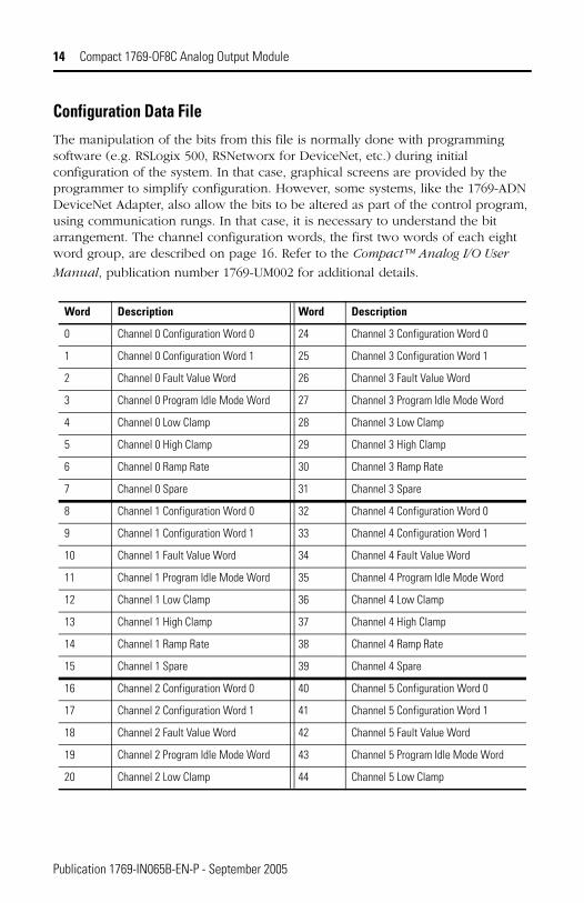
Configuration Data FileThe manipulation of the bits from this file is normally done with programming software (e.g. RSLogix 500, RSNetworx for DeviceNet, etc.) during initial configuration of the system. In that case, graphical screens are provided by the programmer to simplify configuration. However, some systems, like the 1769-ADN DeviceNet Adapter, also allow the bits to be altered as part of the control program, using communication rungs. In that case, it is necessary to understand the bit arrangement. The channel configuration words, the first two words of each eight word group, are described on page 16. Refer to the Compact™ Analog I/O User
Manual, publication number 1769-UM002 for additional details.
Word Description Word Description
0 Channel 0 Configuration Word 0 24 Channel 3 Configuration Word 0
1 Channel 0 Configuration Word 1 25 Channel 3 Configuration Word 1
2 Channel 0 Fault Value Word 26 Channel 3 Fault Value Word
3 Channel 0 Program Idle Mode Word 27 Channel 3 Program Idle Mode Word
4 Channel 0 Low Clamp 28 Channel 3 Low Clamp
5 Channel 0 High Clamp 29 Channel 3 High Clamp
6 Channel 0 Ramp Rate 30 Channel 3 Ramp Rate
7 Channel 0 Spare 31 Channel 3 Spare
8 Channel 1 Configuration Word 0 32 Channel 4 Configuration Word 0
9 Channel 1 Configuration Word 1 33 Channel 4 Configuration Word 1
10 Channel 1 Fault Value Word 34 Channel 4 Fault Value Word
11 Channel 1 Program Idle Mode Word 35 Channel 4 Program Idle Mode Word
12 Channel 1 Low Clamp 36 Channel 4 Low Clamp
13 Channel 1 High Clamp 37 Channel 4 High Clamp
14 Channel 1 Ramp Rate 38 Channel 4 Ramp Rate
15 Channel 1 Spare 39 Channel 4 Spare
16 Channel 2 Configuration Word 0 40 Channel 5 Configuration Word 0
17 Channel 2 Configuration Word 1 41 Channel 5 Configuration Word 1
18 Channel 2 Fault Value Word 42 Channel 5 Fault Value Word
19 Channel 2 Program Idle Mode Word 43 Channel 5 Program Idle Mode Word
20 Channel 2 Low Clamp 44 Channel 5 Low Clamp
Publication 1769-IN065B-EN-P - September 2005

Compact 1769-OF8C Analog Output Module 15
• E = Channel Enable: (0 = Disabled, 1 = output 0 and hold Enabled, process changes)
• Reserved = Set to zero
• SIU = System interrupt low clamp, under-range alarms: (0 = Disabled, 1 = Enabled)
• SIO = System interrupt high clamp, over-range alarms: (0 = Disabled, 1 = Enabled)
• LA = Latch low/high clamp, under/over-range alarms: (0 = Disabled, 1 = Enabled)
• ER = Enable ramping: (0 = Disabled, 1 = Enabled. Ramp rate limited by fault states.)
• FM = Fault mode: (0 = Hold Last State, 1 = User Defined Value)
• PM = Program mode: (0 = Hold Last State, 1 = User Defined Value)
• HI = Hold for initialization: (0 = Disabled, 1 = Enabled)
• PFE = Program/idle to fault enable: (0 = Disabled, 1 = Enabled)
21 Channel 2 High Clamp 45 Channel 5 High Clamp
22 Channel 2 Ramp Rate 46 Channel 5 Ramp Rate
23 Channel 2 Spare 47 Channel 5 Spare
Word Description Word Description
48 Channel 6 Configuration Word 0 56 Channel 7 Configuration Word 0
49 Channel 6 Configuration Word 1 57 Channel 7 Configuration Word 1
50 Channel 6 Fault Value Word 58 Channel 7 Fault Value Word
51 Channel 6 Program Idle Mode Word 59 Channel 7 Program Idle Mode Word
52 Channel 6 Low Clamp 60 Channel 7 Low Clamp
53 Channel 6 High Clamp 61 Channel 7 High Clamp
54 Channel 6 Ramp Rate 62 Channel 7 Ramp Rate
55 Channel 6 Spare 63 Channel 7 Spare
Word/Bit 15 14 13 12 11 10 9 8 7 6 5 4 3 2 1 0
Word 0 E Reserved SIU SIO LA ER FM PM HI PFE
Word 1 Reserved Output Data Format Select
Reserved Output Type/Range
Word Description Word Description
Publication 1769-IN065B-EN-P - September 2005
16 Compact 1769-OF8C Analog Output Module
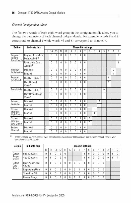
Channel Configuration Words
The first two words of each eight word group in the configuration file allow you to change the parameters of each channel independently. For example, words 8 and 9
correspond to channel 1 while words 56 and 57 correspond to channel 7.
Define Indicate this These bit settings15 14 13 12 11 10 9 8 7 6 5 4 3 2 1 0
Program (Idle) to Fault Enable
Program (Idle) Mode Data Applied(1)
(1) These functions are not supported by all controllers (e.g. MicroLogix 1500) using any configuration method. Refer to your controller manual for details.
0 0 0 0 0 0 0 0 0
Fault Mode Data Applied(1)
0 0 0 0 0 0 0 0 1
Hold for Initialization
Disabled 0 0 0 0 0 0 0 0 0Enabled 0 0 0 0 0 0 0 0 1
Program (Idle) Mode
Hold Last State(1) 0 0 0 0 0 0 0 0 0
User-Defined Value(1)
0 0 0 0 0 0 0 0 1
Fault Mode Hold Last State(1) 0 0 0 0 0 0 0 0 0
User-Defined Fault Value(1)
0 0 0 0 0 0 0 0 1
Enable Ramping
Disabled 0 0 0 0 0 0 0 0 0Enabled 0 0 0 0 0 0 0 0 1
System Interrupt High Clamp
Disabled 0 0 0 0 0 0 0 0 0Enabled 0 0 0 0 0 0 0 0 1
System Interrupt Low Clamp
Disabled 0 0 0 0 0 0 0 0 0Enabled 0 0 0 0 0 0 0 0 1
Enable Channel
Disabled 0 0 0 0 0 0 0 0 0Enabled 1 0 0 0 0 0 0 0 0
Define Indicate this These bit settings15 14 13 12 11 10 9 8 7 6 5 4 3 2 1 0
Output Range Select
0 to 20 mA dc 0 0 0 0 0 0 0 0 0 0 0 0 04 to 20 mA dc 0 0 0 0 0 0 0 0 0 0 0 0 1
Output Data Select
Raw/Proportional Counts
0 0 0 0 0 0 0 0 0 0 0 0 0
Engineering Units 0 0 0 0 0 0 0 1 0 0 0 0 0Scaled for PID 0 0 0 0 0 0 1 0 0 0 0 0 0Percent Range 0 0 0 0 0 0 1 1 0 0 0 0 0
Publication 1769-IN065B-EN-P - September 2005
Compact 1769-OF8C Analog Output Module 17
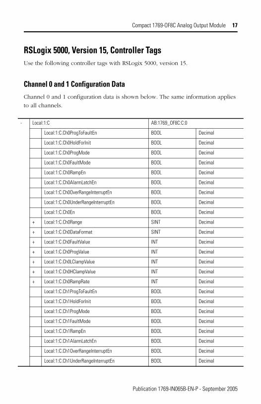
RSLogix 5000, Version 15, Controller TagsUse the following controller tags with RSLogix 5000, version 15.
Channel 0 and 1 Configuration DataChannel 0 and 1 configuration data is shown below. The same information applies
to all channels.
- Local:1:C AB:1769_OF8C:C:0
Local:1:C.Ch0ProgToFaultEn BOOL Decimal
Local:1:C.Ch0HoldForInit BOOL Decimal
Local:1:C.Ch0ProgMode BOOL Decimal
Local:1:C.Ch0FaultMode BOOL Decimal
Local:1:C.Ch0RampEn BOOL Decimal
Local:1:C.Ch0AlarmLatchEn BOOL Decimal
Local:1:C.Ch0OverRangeInterruptEn BOOL Decimal
Local:1:C.Ch0UnderRangeInterruptEn BOOL Decimal
Local:1:C.Ch0En BOOL Decimal
+ Local:1:C.Ch0Range SINT Decimal
+ Local:1:C.Ch0DataFormat SINT Decimal
+ Local:1:C.Ch0FaultValue INT Decimal
+ Local:1:C.Ch0ProgValue INT Decimal
+ Local:1:C.Ch0LClampValue INT Decimal
+ Local:1:C.Ch0HClampValue INT Decimal
+ Local:1:C.Ch0RampRate INT Decimal
Local:1:C.Ch1ProgToFaultEn BOOL Decimal
Local:1:C.Ch1HoldForInit BOOL Decimal
Local:1:C.Ch1ProgMode BOOL Decimal
Local:1:C.Ch1FaultMode BOOL Decimal
Local:1:C.Ch1RampEn BOOL Decimal
Local:1:C.Ch1AlarmLatchEn BOOL Decimal
Local:1:C.Ch1OverRangeInterruptEn BOOL Decimal
Local:1:C.Ch1UnderRangeInterruptEn BOOL Decimal
Publication 1769-IN065B-EN-P - September 2005
18 Compact 1769-OF8C Analog Output Module
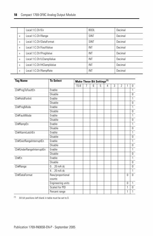
Local:1:C.Ch1En BOOL Decimal
+ Local:1:C.Ch1Range SINT Decimal
+ Local:1:C.Ch1DataFormat SINT Decimal
+ Local:1:C.Ch1FaultValue INT Decimal
+ Local:1:C.Ch1ProgValue INT Decimal
+ Local:1:C.Ch1LClampValue INT Decimal
+ Local:1:C.Ch1HClampValue INT Decimal
+ Local:1:C.Ch1RampRate INT Decimal
Tag Name To Select Make These Bit Settings(1)
15-8 7 6 5 4 3 2 1 0Ch#ProgToFaultEn Enable 1
Disable 0Ch#HoldForInit Enable 1
Disable 0Ch#ProgMode Enable 1
Disable 0Ch#FaultMode Enable 1
Disable 0Ch#RampEn Enable 1
Disable 0Ch#AlarmLatchEn Enable 1
Disable 0Ch#OverRangeInterruptEn Enable 1
Disable 0Ch#UnderRangeInterruptEn Enable 1
Disable 0Ch#En Enable 1
Disable 0Ch#Range 0…20 mA dc 0
4…20 mA dc 1Ch#DataFormat Raw/proportional
counts0 0
Engineering units 0 1Scaled for PID 1 0Percent range 1 1
(1) All bit positions left blank in table must be set to 0.
Publication 1769-IN065B-EN-P - September 2005
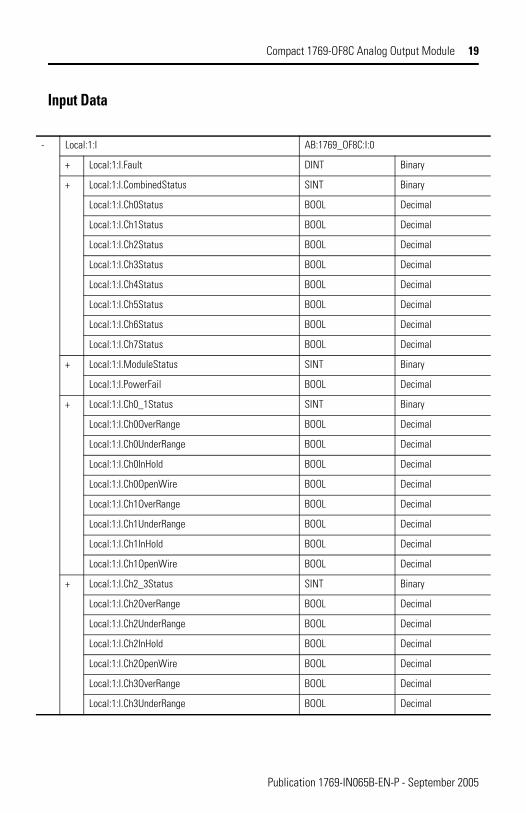
Compact 1769-OF8C Analog Output Module 19
Input Data
- Local:1:I AB:1769_OF8C:I:0
+ Local:1:I.Fault DINT Binary
+ Local:1:I.CombinedStatus SINT Binary
Local:1:I.Ch0Status BOOL Decimal
Local:1:I.Ch1Status BOOL Decimal
Local:1:I.Ch2Status BOOL Decimal
Local:1:I.Ch3Status BOOL Decimal
Local:1:I.Ch4Status BOOL Decimal
Local:1:I.Ch5Status BOOL Decimal
Local:1:I.Ch6Status BOOL Decimal
Local:1:I.Ch7Status BOOL Decimal
+ Local:1:I.ModuleStatus SINT Binary
Local:1:I.PowerFail BOOL Decimal
+ Local:1:I.Ch0_1Status SINT Binary
Local:1:I.Ch0OverRange BOOL Decimal
Local:1:I.Ch0UnderRange BOOL Decimal
Local:1:I.Ch0InHold BOOL Decimal
Local:1:I.Ch0OpenWire BOOL Decimal
Local:1:I.Ch1OverRange BOOL Decimal
Local:1:I.Ch1UnderRange BOOL Decimal
Local:1:I.Ch1InHold BOOL Decimal
Local:1:I.Ch1OpenWire BOOL Decimal
+ Local:1:I.Ch2_3Status SINT Binary
Local:1:I.Ch2OverRange BOOL Decimal
Local:1:I.Ch2UnderRange BOOL Decimal
Local:1:I.Ch2InHold BOOL Decimal
Local:1:I.Ch2OpenWire BOOL Decimal
Local:1:I.Ch3OverRange BOOL Decimal
Local:1:I.Ch3UnderRange BOOL Decimal
Publication 1769-IN065B-EN-P - September 2005
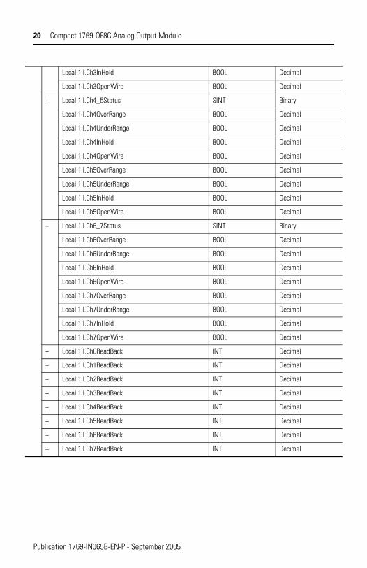
20 Compact 1769-OF8C Analog Output Module
Local:1:I.Ch3InHold BOOL Decimal
Local:1:I.Ch3OpenWire BOOL Decimal
+ Local:1:I.Ch4_5Status SINT Binary
Local:1:I.Ch4OverRange BOOL Decimal
Local:1:I.Ch4UnderRange BOOL Decimal
Local:1:I.Ch4InHold BOOL Decimal
Local:1:I.Ch4OpenWire BOOL Decimal
Local:1:I.Ch5OverRange BOOL Decimal
Local:1:I.Ch5UnderRange BOOL Decimal
Local:1:I.Ch5InHold BOOL Decimal
Local:1:I.Ch5OpenWire BOOL Decimal
+ Local:1:I.Ch6_7Status SINT Binary
Local:1:I.Ch6OverRange BOOL Decimal
Local:1:I.Ch6UnderRange BOOL Decimal
Local:1:I.Ch6InHold BOOL Decimal
Local:1:I.Ch6OpenWire BOOL Decimal
Local:1:I.Ch7OverRange BOOL Decimal
Local:1:I.Ch7UnderRange BOOL Decimal
Local:1:I.Ch7InHold BOOL Decimal
Local:1:I.Ch7OpenWire BOOL Decimal
+ Local:1:I.Ch0ReadBack INT Decimal
+ Local:1:I.Ch1ReadBack INT Decimal
+ Local:1:I.Ch2ReadBack INT Decimal
+ Local:1:I.Ch3ReadBack INT Decimal
+ Local:1:I.Ch4ReadBack INT Decimal
+ Local:1:I.Ch5ReadBack INT Decimal
+ Local:1:I.Ch6ReadBack INT Decimal
+ Local:1:I.Ch7ReadBack INT Decimal
Publication 1769-IN065B-EN-P - September 2005
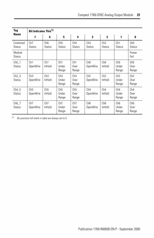
Compact 1769-OF8C Analog Output Module 21
Tag Name
Bit Indicates This(1)
7 6 5 4 3 2 1 0
Combined Status
Ch7 Status
Ch6 Status
Ch5 Status
Ch4 Status
Ch3 Status
Ch2 Status
Ch1 Status
Ch0 Status
Module Status
Power Fail
Ch0_1 Status
Ch1 OpenWire
Ch1 InHold
Ch1 Under Range
Ch1 Over Range
Ch0 OpenWire
Ch0 InHold
Ch0 Under Range
Ch0 Over Range
Ch2_3 Status
Ch3 OpenWire
Ch3 InHold
Ch3 Under Range
Ch3 Over Range
Ch2 OpenWire
Ch2 InHold
Ch2 Under Range
Ch2 Over Range
Ch4_5 Status
Ch5 OpenWire
Ch5 InHold
Ch5 Under Range
Ch5 Over Range
Ch4 OpenWire
Ch4 InHold
Ch4 Under Range
Ch4 Over Range
Ch6_7 Status
Ch7 OpenWire
Ch7 InHold
Ch7 Under Range
Ch7 Over Range
Ch6 OpenWire
Ch6 InHold
Ch6 Under Range
Ch6 Over Range
(1) Bit positions left blank in table are always set to 0.
Publication 1769-IN065B-EN-P - September 2005
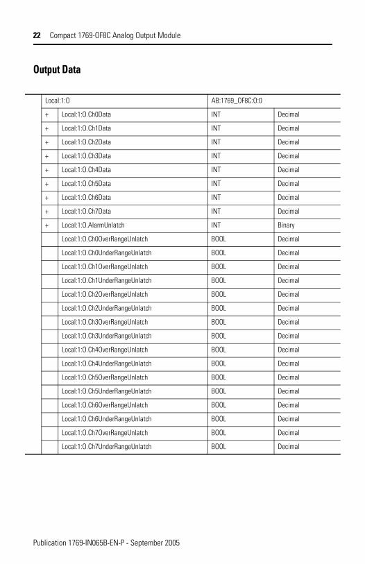
22 Compact 1769-OF8C Analog Output Module
Output Data
Local:1:O AB:1769_OF8C:O:0
+ Local:1:O.Ch0Data INT Decimal
+ Local:1:O.Ch1Data INT Decimal
+ Local:1:O.Ch2Data INT Decimal
+ Local:1:O.Ch3Data INT Decimal
+ Local:1:O.Ch4Data INT Decimal
+ Local:1:O.Ch5Data INT Decimal
+ Local:1:O.Ch6Data INT Decimal
+ Local:1:O.Ch7Data INT Decimal
+ Local:1:O.AlarmUnlatch INT Binary
Local:1:O.Ch0OverRangeUnlatch BOOL Decimal
Local:1:O.Ch0UnderRangeUnlatch BOOL Decimal
Local:1:O.Ch1OverRangeUnlatch BOOL Decimal
Local:1:O.Ch1UnderRangeUnlatch BOOL Decimal
Local:1:O.Ch2OverRangeUnlatch BOOL Decimal
Local:1:O.Ch2UnderRangeUnlatch BOOL Decimal
Local:1:O.Ch3OverRangeUnlatch BOOL Decimal
Local:1:O.Ch3UnderRangeUnlatch BOOL Decimal
Local:1:O.Ch4OverRangeUnlatch BOOL Decimal
Local:1:O.Ch4UnderRangeUnlatch BOOL Decimal
Local:1:O.Ch5OverRangeUnlatch BOOL Decimal
Local:1:O.Ch5UnderRangeUnlatch BOOL Decimal
Local:1:O.Ch6OverRangeUnlatch BOOL Decimal
Local:1:O.Ch6UnderRangeUnlatch BOOL Decimal
Local:1:O.Ch7OverRangeUnlatch BOOL Decimal
Local:1:O.Ch7UnderRangeUnlatch BOOL Decimal
Publication 1769-IN065B-EN-P - September 2005
Compact 1769-OF8C Analog Output Module 23
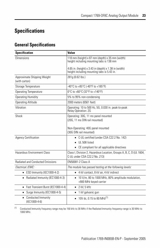
Specifications
General Specifications
Specification Value
Dimensions 118 mm (height) x 87 mm (depth) x 35 mm (width) height including mounting tabs is 138 mm
4.65 in. (height) x 3.43 in (depth) x 1.38 in (width) height including mounting tabs is 5.43 in.
Approximate Shipping Weight (with carton)
281g (0.62 lbs.)
Storage Temperature -40°C to +85°C (-40°F to +185°F)
Operating Temperature 0°C to +60°C (32°F to +140°F)
Operating Humidity 5% to 95% non-condensing
Operating Altitude 2000 meters (6561 feet)
Vibration Operating: 10 to 500 Hz, 5G, 0.030 in. peak-to-peak Relay Operation: 2G
Shock Operating: 30G, 11 ms panel mounted (20G, 11 ms DIN rail mounted)
Non-Operating: 40G panel mounted (30G DIN rail mounted)
Agency Certification • C-UL certified (under CSA C22.2 No. 142)• UL 508 listed• CE compliant for all applicable directives
Hazardous Environment Class Class I, Division 2, Hazardous Location, Groups A, B, C, D (UL 1604, C-UL under CSA C22.2 No. 213)
Radiated and Conducted Emissions EN50081-2 Class A
Electrical /EMC: The module has passed testing at the following levels:
• ESD Immunity (IEC1000-4-2) • 4 kV contact, 8 kV air, 4 kV indirect
• Radiated Immunity (IEC1000-4-3) • 10 V/m, 80 to 1000 MHz, 80% amplitude modulation, +900 MHz keyed carrier
• Fast Transient Burst (IEC1000-4-4) • 2 kV, 5 kHz
• Surge Immunity (IEC1000-4-5) • 1 kV galvanic gun
• Conducted Immunity (IEC1000-4-6)
• 10V dc, 0.15 to 80 MHz(1)
(1) Conducted Immunity frequency range may be 150 kHz to 30 MHz if the Radiated Immunity frequency range is 30 MHz to 1000 MHz.
Publication 1769-IN065B-EN-P - September 2005
24 Compact 1769-OF8C Analog Output Module
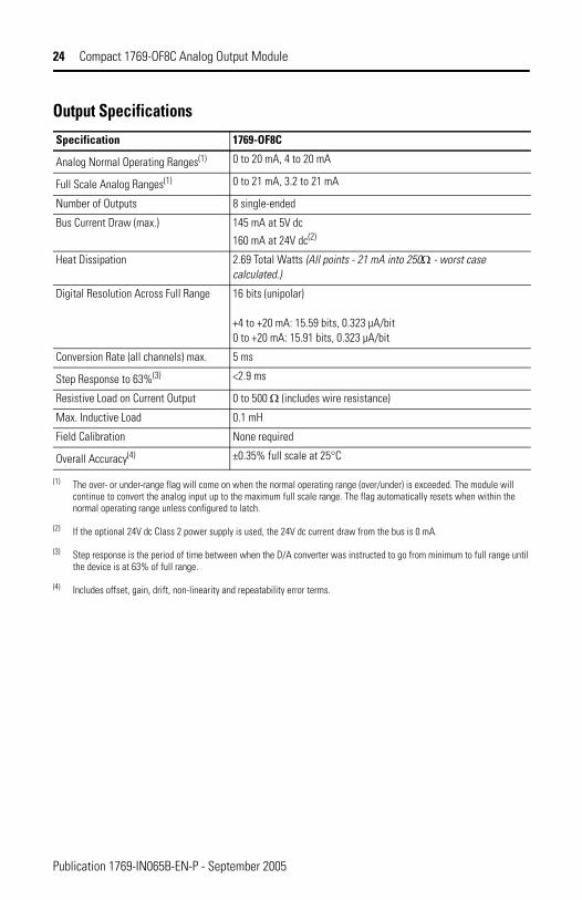
Output Specifications
Specification 1769-OF8C
Analog Normal Operating Ranges(1)
(1) The over- or under-range flag will come on when the normal operating range (over/under) is exceeded. The module will continue to convert the analog input up to the maximum full scale range. The flag automatically resets when within the normal operating range unless configured to latch.
0 to 20 mA, 4 to 20 mA
Full Scale Analog Ranges(1) 0 to 21 mA, 3.2 to 21 mA
Number of Outputs 8 single-ended
Bus Current Draw (max.) 145 mA at 5V dc 160 mA at 24V dc(2)
(2) If the optional 24V dc Class 2 power supply is used, the 24V dc current draw from the bus is 0 mA.
Heat Dissipation 2.69 Total Watts (All points - 21 mA into 250Ω - worst case calculated.)
Digital Resolution Across Full Range 16 bits (unipolar)
+4 to +20 mA: 15.59 bits, 0.323 µA/bit 0 to +20 mA: 15.91 bits, 0.323 µA/bit
Conversion Rate (all channels) max. 5 ms
Step Response to 63%(3)
(3) Step response is the period of time between when the D/A converter was instructed to go from minimum to full range until the device is at 63% of full range.
<2.9 ms
Resistive Load on Current Output 0 to 500 Ω (includes wire resistance)
Max. Inductive Load 0.1 mH
Field Calibration None required
Overall Accuracy(4)
(4) Includes offset, gain, drift, non-linearity and repeatability error terms.
±0.35% full scale at 25°C
Publication 1769-IN065B-EN-P - September 2005
Compact 1769-OF8C Analog Output Module 25
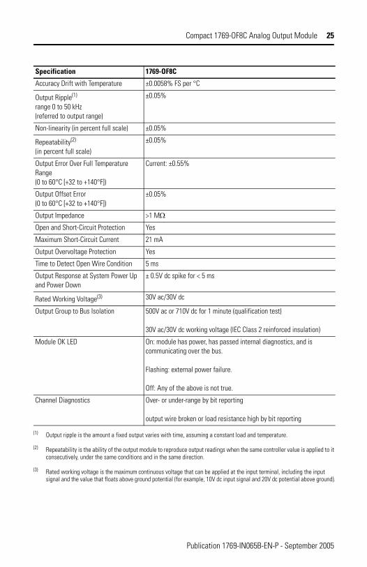
Specification 1769-OF8C
Accuracy Drift with Temperature ±0.0058% FS per °C
Output Ripple(1) range 0 to 50 kHz (referred to output range)
±0.05%
Non-linearity (in percent full scale) ±0.05%
Repeatability(2) (in percent full scale)
±0.05%
Output Error Over Full Temperature Range (0 to 60°C [+32 to +140°F])
Current: ±0.55%
Output Offset Error (0 to 60°C [+32 to +140°F])
±0.05%
Output Impedance >1 MΩ
Open and Short-Circuit Protection Yes
Maximum Short-Circuit Current 21 mA
Output Overvoltage Protection Yes
Time to Detect Open Wire Condition 5 ms
Output Response at System Power Up and Power Down
± 0.5V dc spike for < 5 ms
Rated Working Voltage(3) 30V ac/30V dc
Output Group to Bus Isolation 500V ac or 710V dc for 1 minute (qualification test)
30V ac/30V dc working voltage (IEC Class 2 reinforced insulation)
Module OK LED On: module has power, has passed internal diagnostics, and is communicating over the bus.
Flashing: external power failure.
Off: Any of the above is not true.
Channel Diagnostics Over- or under-range by bit reporting
output wire broken or load resistance high by bit reporting
(1) Output ripple is the amount a fixed output varies with time, assuming a constant load and temperature.
(2) Repeatability is the ability of the output module to reproduce output readings when the same controller value is applied to it consecutively, under the same conditions and in the same direction.
(3) Rated working voltage is the maximum continuous voltage that can be applied at the input terminal, including the input signal and the value that floats above ground potential (for example, 10V dc input signal and 20V dc potential above ground).
Publication 1769-IN065B-EN-P - September 2005
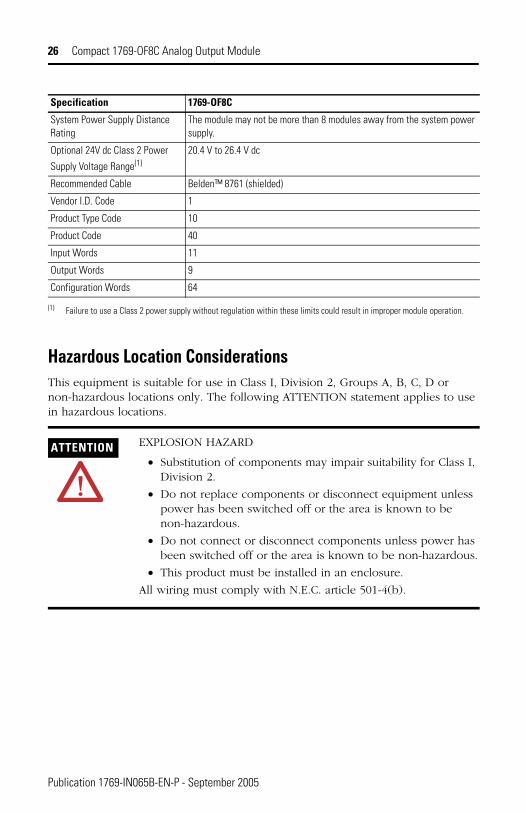
26 Compact 1769-OF8C Analog Output Module
Hazardous Location ConsiderationsThis equipment is suitable for use in Class I, Division 2, Groups A, B, C, D or non-hazardous locations only. The following ATTENTION statement applies to use in hazardous locations.
Specification 1769-OF8C
System Power Supply Distance Rating
The module may not be more than 8 modules away from the system power supply.
Optional 24V dc Class 2 Power
Supply Voltage Range(1)20.4 V to 26.4 V dc
Recommended Cable Belden™ 8761 (shielded)
Vendor I.D. Code 1
Product Type Code 10
Product Code 40
Input Words 11
Output Words 9
Configuration Words 64
(1) Failure to use a Class 2 power supply without regulation within these limits could result in improper module operation.
ATTENTION EXPLOSION HAZARD
• Substitution of components may impair suitability for Class I, Division 2.
• Do not replace components or disconnect equipment unless power has been switched off or the area is known to be non-hazardous.
• Do not connect or disconnect components unless power has been switched off or the area is known to be non-hazardous.
• This product must be installed in an enclosure.
All wiring must comply with N.E.C. article 501-4(b).
Publication 1769-IN065B-EN-P - September 2005
Compact 1769-OF8C Analog Output Module 27
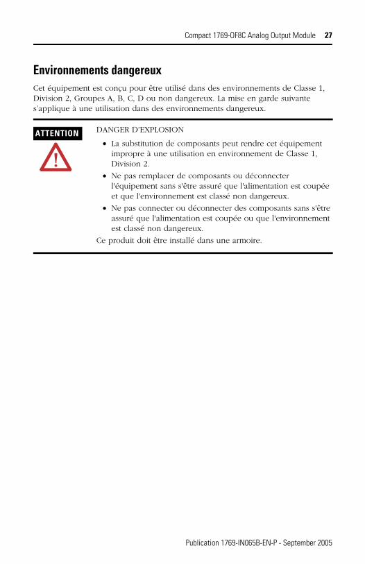
Environnements dangereuxCet équipement est conçu pour être utilisé dans des environnements de Classe 1, Division 2, Groupes A, B, C, D ou non dangereux. La mise en garde suivante s’applique à une utilisation dans des environnements dangereux.
ATTENTION DANGER D’EXPLOSION
• La substitution de composants peut rendre cet équipement impropre à une utilisation en environnement de Classe 1, Division 2.
• Ne pas remplacer de composants ou déconnecter l'équipement sans s'être assuré que l'alimentation est coupée et que l'environnement est classé non dangereux.
• Ne pas connecter ou déconnecter des composants sans s'être assuré que l'alimentation est coupée ou que l'environnement est classé non dangereux.
Ce produit doit être installé dans une armoire.
Publication 1769-IN065B-EN-P - September 2005

28 Compact 1769-OF8C Analog Output Module
For More Information
If you would like a manual, you can:
• download a free electronic version from the internet: www.ab.com/micrologix or www.theautomationbookstore.com
• purchase a printed manual by:
– contacting your local distributor or Rockwell Automation representative– visiting www.theautomationbookstore.com and placing your order– calling 1.800.963.9548 (USA/Canada)
or 001.330.725.1574 (Outside USA/Canada)
MicroLogix and Compact are trademarks of Rockwell Automation. Belden is a trademark of Belden, Inc.
For Refer to this Document Pub. No.
A more detailed description of how to install and use your Compact I/O with MicroLogix 1500 programmable controller.
MicroLogix 1500 Programmable Controllers User Manual
1764-UM001A-US-P
Detailed information on installing, programming, and troubleshooting your Compact Analog I/O modules.
Compact I/O Analog Modules User Manual
1769-UM002A-EN-P
A detailed description of how to install and use your Compact I/O with the 1769-ADN DeviceNet Adapter.
1769-ADN DeviceNet Adapter User Manual
1769-UM001A-US-P
An overview of the MicroLogix 1500 system, including Compact I/O.
MicroLogix 1500 Programmable Controller with Compact I/O for Expansion
1764-SO001B-EN-P
More information on proper wiring and grounding techniques.
Industrial Automation Wiring and Grounding Guidelines
1770-4.1
Publication 1769-IN065B-EN-P - September 2005
Compact 1769-OF8C Analog Output Module 29
Notes:
Publication 1769-IN065B-EN-P - September 2005

30 Compact 1769-OF8C Analog Output Module
Notes:
Publication 1769-IN065B-EN-P - September 2005

Compact 1769-OF8C Analog Output Module 31
Notes:
Publication 1769-IN065B-EN-P - September 2005
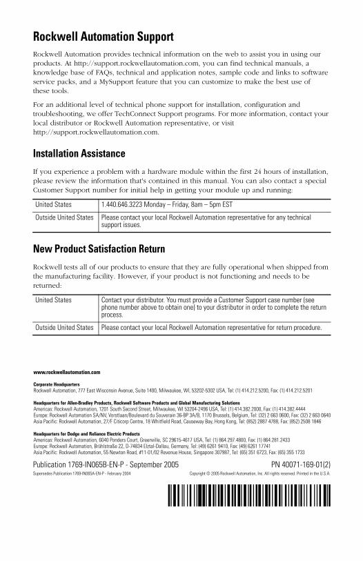
Rockwell Automation SupportRockwell Automation provides technical information on the web to assist you in using our
Publication 1769-IN065B-EN-P - September 2005 PN 40071-169-01(2)Supersedes Publication 1769-IN065A-EN-P - February 2004 Copyright © 2005 Rockwell Automation, Inc. All rights reserved. Printed in the U.S.A.
´H'¶1-169-01(2)+¨
products. At http://support.rockwellautomation.com, you can find technical manuals, a knowledge base of FAQs, technical and application notes, sample code and links to software service packs, and a MySupport feature that you can customize to make the best use of these tools.
For an additional level of technical phone support for installation, configuration and troubleshooting, we offer TechConnect Support programs. For more information, contact your local distributor or Rockwell Automation representative, or visit http://support.rockwellautomation.com.
Installation Assistance
If you experience a problem with a hardware module within the first 24 hours of installation, please review the information that's contained in this manual. You can also contact a special Customer Support number for initial help in getting your module up and running:
New Product Satisfaction Return
Rockwell tests all of our products to ensure that they are fully operational when shipped from the manufacturing facility. However, if your product is not functioning and needs to be returned:
United States 1.440.646.3223 Monday – Friday, 8am – 5pm EST
Outside United States Please contact your local Rockwell Automation representative for any technical support issues.
United States Contact your distributor. You must provide a Customer Support case number (see phone number above to obtain one) to your distributor in order to complete the return process.
Outside United States Please contact your local Rockwell Automation representative for return procedure.