Embed Size (px)
Citation preview
ASPRS 2007 Annual Conference Tampa, Florida ♦ May 7-11, 2007
COMPARATIVE ANALYSIS OF ALTERNATIVE METHODOLOGIES FOR TRUE ORTHO-PHOTO GENERATION FROM HIGH RESOLUTION
SATELLITE IMAGERY
K. I. Bang A. F. Habib
Department of Geomatics Engineering University of Calgary Calgary, AB, Canada
[email protected] [email protected]
S. W. Shin K. O. Kim
Spatial Information Research Team Electronics and Telecommunications Research Institute
Daejeon, Republic of Korea [email protected]
ABSTRACT
Ortho-photos provide valuable spatial and spectral information for various GIS and mapping applications. The absence of relief displacement and the uniform scale in ortho-photos enable interested users to measure distances, compute areas, derive geographic locations, and quantify changes. Differential rectification has traditionally been used for ortho-photo generation. However, differential rectification produces serious problems (in the form of ghost images) when dealing with large scale imagery over urban areas. To avoid these artifacts, true ortho-photo generation techniques have been devised to remove ghost images through visibility analysis and occlusion detection. So far, the z-buffer method has been one of the most popular methods for true ortho-photo generation. However, it has strict requirements regarding the cell size of the Digital Surface Model (DSM), as the cell size is related to the Ground Sampling Distance (GSD) of the imaging sensor. This paper introduces alternative methodologies for true ortho-photo generation that circumvent the drawbacks of the z-buffer technique. Moreover, the proposed techniques are specially suited for manipulating scenes acquired by high resolution imaging satellites. Specifically, the proposed methodologies focus on object to image projection and occlusion detection when dealing with line cameras. Using real data, the experimental results section describes a comprehensive analysis of the performance of the proposed methodologies when compared to existing techniques. The analysis focuses on the quality of detected occlusions and the computational efficiency.
INTRODUCTION
Ortho-photo production aims to eliminate sensor tilt and terrain relief effects from captured perspective imagery. Uniform scale and the absence of relief displacement make ortho-photos an important component of GIS databases, in which the user can directly determine geographic locations, measure distances, compute areas, and derive other useful information about the area in question. Recently, with the increasing resolution of modern imaging satellites (e.g. half a meter ground resolution imagery will be offered by OrbView-5, to be launched in 2007), there has been a persistent need for a true ortho-photo generation methodology that is capable of dealing with the imagery acquired from such systems.
Differential rectification has traditionally been used for ortho-photo generation. The performance of differential rectification procedures has been quite acceptable when dealing with medium resolution imagery over relatively smooth terrain. However, when dealing with high resolution imagery over urban areas, differential rectification produces artifacts in the form of ghost images (double-mapped areas) at the vicinity of abrupt surface changes (e.g. at building boundaries and steep cliffs). The effects of these artifacts can be mitigated by true ortho-photo generation methodologies.
ASPRS 2007 Annual Conference Tampa, Florida ♦ May 7-11, 2007
The term ‘true ortho photo’ is generally used for ortho-photos in which surface elements that are not included in the digital terrain model (DTM) are rectified to the orthogonal projection. These elements are usually buildings and bridges (Amhar, 1998). Kuzmin et al. (2004) proposed a polygon-based approach for the detection of these obscured areas in order to generate true ortho-photos. In this method, conventional digital differential rectification is first applied. Afterwards, hidden areas are detected through the use of polygonal surfaces generated from a Digital Building Model (DBM). With the exception of the methodology proposed by Kuzmin et al., the majority of existing true ortho-photo generation techniques are based on the z-buffer method (Catmull, 1974; Amhar et al., 1998; Rau et al., 2000; Rau et al., 2002; Sheng et al., 2003).
In this paper, existing methods for ortho-photo generation are discussed comprehensively with a focus on line scanner imagery, and new alternatives are introduced along with experiments used to test them.
FORWARD AND BACKWARD PROJECTION There are two basic approaches to generating an ortho-photo: forward projection and backward projection (Novak, 1992). In forward projection, each pixel in the source image is projected onto the ortho-photo; the corresponding pixels in the ortho-photo are then determined via the intersection of a ray from the perspective center of the source image through the image point with the three dimensional ground surface defined by the DSM. In backward projection, each pixel in the ortho-photo takes its pixel value from the source image using the collinearity condition and the object space coordinates X, Y, and Z of the corresponding DSM cell.
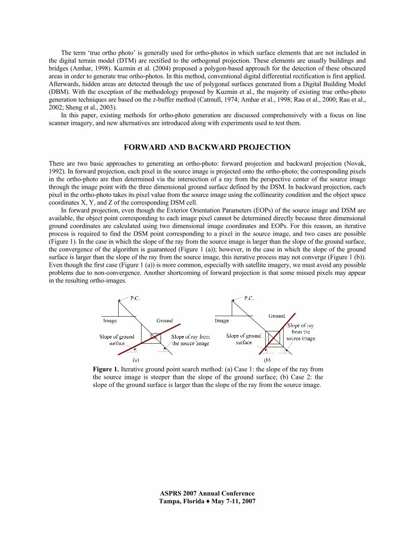
In forward projection, even though the Exterior Orientation Parameters (EOPs) of the source image and DSM are available, the object point corresponding to each image pixel cannot be determined directly because three dimensional ground coordinates are calculated using two dimensional image coordinates and EOPs. For this reason, an iterative process is required to find the DSM point corresponding to a pixel in the source image, and two cases are possible (Figure 1). In the case in which the slope of the ray from the source image is larger than the slope of the ground surface, the convergence of the algorithm is guaranteed (Figure 1 (a)); however, in the case in which the slope of the ground surface is larger than the slope of the ray from the source image, this iterative process may not converge (Figure 1 (b)). Even though the first case (Figure 1 (a)) is more common, especially with satellite imagery, we must avoid any possible problems due to non-convergence. Another shortcoming of forward projection is that some missed pixels may appear in the resulting ortho-images.
Figure 1. Iterative ground point search method: (a) Case 1: the slope of the ray from the source image is steeper than the slope of the ground surface; (b) Case 2: the slope of the ground surface is larger than the slope of the ray from the source image.
ASPRS 2007 Annual Conference Tampa, Florida ♦ May 7-11, 2007
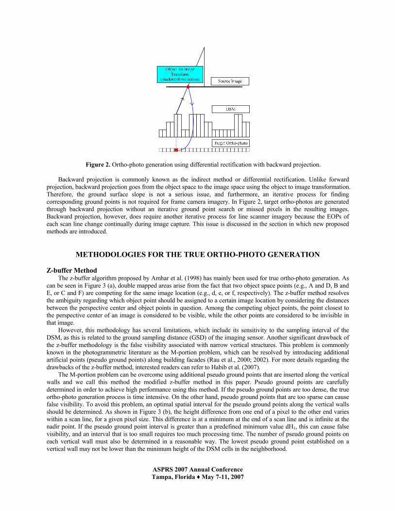
Figure 2. Ortho-photo generation using differential rectification with backward projection. Backward projection is commonly known as the indirect method or differential rectification. Unlike forward
projection, backward projection goes from the object space to the image space using the object to image transformation. Therefore, the ground surface slope is not a serious issue, and furthermore, an iterative process for finding corresponding ground points is not required for frame camera imagery. In Figure 2, target ortho-photos are generated through backward projection without an iterative ground point search or missed pixels in the resulting images. Backward projection, however, does require another iterative process for line scanner imagery because the EOPs of each scan line change continually during image capture. This issue is discussed in the section in which new proposed methods are introduced.
METHODOLOGIES FOR THE TRUE ORTHO-PHOTO GENERATION
Z-buffer Method The z-buffer algorithm proposed by Amhar et al. (1998) has mainly been used for true ortho-photo generation. As
can be seen in Figure 3 (a), double mapped areas arise from the fact that two object space points (e.g., A and D, B and E, or C and F) are competing for the same image location (e.g., d, e, or f, respectively). The z-buffer method resolves the ambiguity regarding which object point should be assigned to a certain image location by considering the distances between the perspective center and object points in question. Among the competing object points, the point closest to the perspective center of an image is considered to be visible, while the other points are considered to be invisible in that image.
However, this methodology has several limitations, which include its sensitivity to the sampling interval of the DSM, as this is related to the ground sampling distance (GSD) of the imaging sensor. Another significant drawback of the z-buffer methodology is the false visibility associated with narrow vertical structures. This problem is commonly known in the photogrammetric literature as the M-portion problem, which can be resolved by introducing additional artificial points (pseudo ground points) along building facades (Rau et al., 2000; 2002). For more details regarding the drawbacks of the z-buffer method, interested readers can refer to Habib et al. (2007).
The M-portion problem can be overcome using additional pseudo ground points that are inserted along the vertical walls and we call this method the modified z-buffer method in this paper. Pseudo ground points are carefully determined in order to achieve high performance using this method. If the pseudo ground points are too dense, the true ortho-photo generation process is time intensive. On the other hand, pseudo ground points that are too sparse can cause false visibility. To avoid this problem, an optimal spatial interval for the pseudo ground points along the vertical walls should be determined. As shown in Figure 3 (b), the height difference from one end of a pixel to the other end varies within a scan line, for a given pixel size. This difference is at a minimum at the end of a scan line and is infinite at the nadir point. If the pseudo ground point interval is greater than a predefined minimum value dH1, this can cause false visibility, and an interval that is too small requires too much processing time. The number of pseudo ground points on each vertical wall must also be determined in a reasonable way. The lowest pseudo ground point established on a vertical wall may not be lower than the minimum height of the DSM cells in the neighborhood.

ASPRS 2007 Annual Conference Tampa, Florida ♦ May 7-11, 2007
Figure 3. (a) True ortho-photo generation using the z-buffer method, and (b) optimal spatial interval for the pseudo ground points.
Using the common properties of the ground observation images, we can improve the z-buffer method. As
mentioned previously, the distances from the objects to the perspective center are recorded to determine the visibility of each DSM cell. In general, aerial photos and satellite images are captured by imaging sensors above the object space; therefore, higher points on the object space are closer to the perspective center than lower points. For this reason, if the elevations of DSM cells are used directly instead of distances, the same results can be obtained with the advantage of better performance. In this study, we call this method the height-buffer method.
Angle Based True Ortho-photo Generation
Habib et al. (2005) proposed two methods for true ortho-photo generation using imagery captured by frame cameras: 1) the Adaptive Radial Sweep Method, and 2) the Spiral Sweep Method. These methods depend on the angle between the nadir direction and the line connecting the perspective center to a certain DSM cell. The top and bottom of a vertical structure are projected onto the same location in the absence of relief displacement. However, in a perspective projection, the top and bottom of that structure are projected as two points. These points are not at the same location; they are spatially separated by the relief displacement. This displacement takes place along a radial direction from the image space nadir point (Mikhail, 2001); relief displacement is the cause of occlusions in perspective imagery. The presence of occlusions can be discerned by sequentially checking the off-nadir angles to the lines of sight connecting the perspective center to the DSM points, along a radial direction starting with the object space nadir point. This is the Angle Based Method (Figure 4).
Angle based methods are feasible for frame imagery because in these images, only one nadir point is present. Therefore, the occlusion search can be done along the radial direction from the nadir point. However, in images captured from line scanner, we must consider the multiple exposure positions. In this research, we investigate the feasibility of extending the angle based method to imagery captured by line cameras.
α
Figure 4. True ortho-photo generation using the Angle Based Method
ASPRS 2007 Annual Conference Tampa, Florida ♦ May 7-11, 2007
PROPOSED METHODS
Removing Occlusion Areas Using the Sorted DEM Method Another alternative for true ortho-photo generation using backward projection is a method that uses a sorted DEM.
If the DSM is sorted according to height values, the true ortho-photo is easily obtained and the resultant image is the same as that obtained using the z-buffer method. Ortho-photo pixels are filled in the order of their heights, and each pixel in the source image is accessed only once. Thus, only visible points in the object space are assigned pixel values, and the required memory is less than that of z-buffer method.
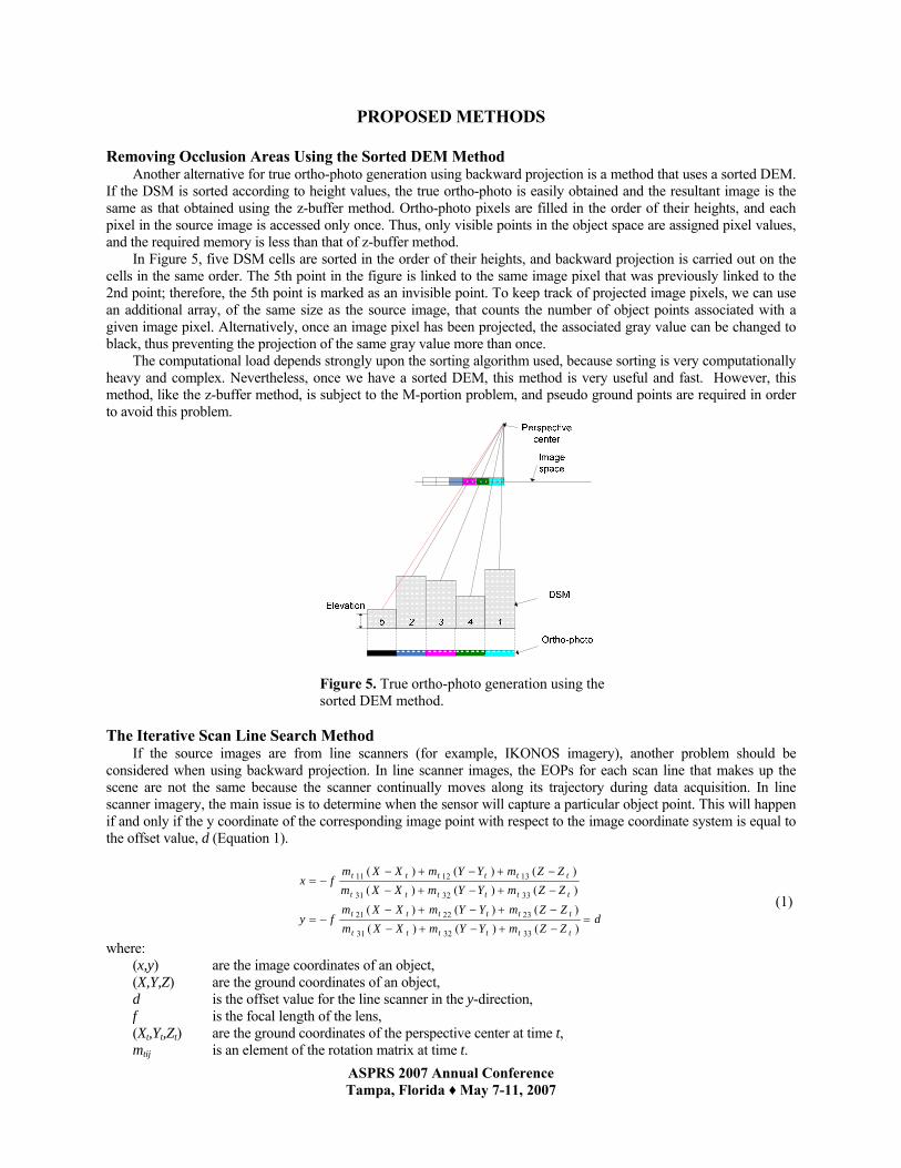
In Figure 5, five DSM cells are sorted in the order of their heights, and backward projection is carried out on the cells in the same order. The 5th point in the figure is linked to the same image pixel that was previously linked to the 2nd point; therefore, the 5th point is marked as an invisible point. To keep track of projected image pixels, we can use an additional array, of the same size as the source image, that counts the number of object points associated with a given image pixel. Alternatively, once an image pixel has been projected, the associated gray value can be changed to black, thus preventing the projection of the same gray value more than once.
The computational load depends strongly upon the sorting algorithm used, because sorting is very computationally heavy and complex. Nevertheless, once we have a sorted DEM, this method is very useful and fast. However, this method, like the z-buffer method, is subject to the M-portion problem, and pseudo ground points are required in order to avoid this problem.
Figure 5. True ortho-photo generation using the sorted DEM method.
The Iterative Scan Line Search Method
If the source images are from line scanners (for example, IKONOS imagery), another problem should be considered when using backward projection. In line scanner images, the EOPs for each scan line that makes up the scene are not the same because the scanner continually moves along its trajectory during data acquisition. In line scanner imagery, the main issue is to determine when the sensor will capture a particular object point. This will happen if and only if the y coordinate of the corresponding image point with respect to the image coordinate system is equal to the offset value, d (Equation 1).
dZZmYYmXXmZZmYYmXXm
fy
ZZmYYmXXmZZmYYmXXm
fx
tttttt
tttttt
tttttt
tttttt
=−+−+−
−+−+−−=
−+−+−
−+−+−−=
)()()()()()()()()()()()(
333231
232221
333231
131211
(1)
where: (x,y) are the image coordinates of an object, (X,Y,Z) are the ground coordinates of an object, d is the offset value for the line scanner in the y-direction, f is the focal length of the lens, (Xt,Yt,Zt) are the ground coordinates of the perspective center at time t, mtij is an element of the rotation matrix at time t.
ASPRS 2007 Annual Conference Tampa, Florida ♦ May 7-11, 2007
In order to generate ortho-photos using line scanner images, an additional iterative process is required in order to find the perspective center corresponding to each ground point. For this problem, Habib et al. (1997) solved the polynomials of the trajectory using Newton Raphson’s Method. Kim et al. (2001) proposed a method of determining 2D image coordinates using 3D object space coordinates; this method requires solving a 2nd order polynomial to identify the appropriate exposure station. In this paper, the ‘Iterative Scan Line Search Method’ is introduced as an alternative method of determining a scan line regardless of the trajectory model employed, without using numerical analysis.
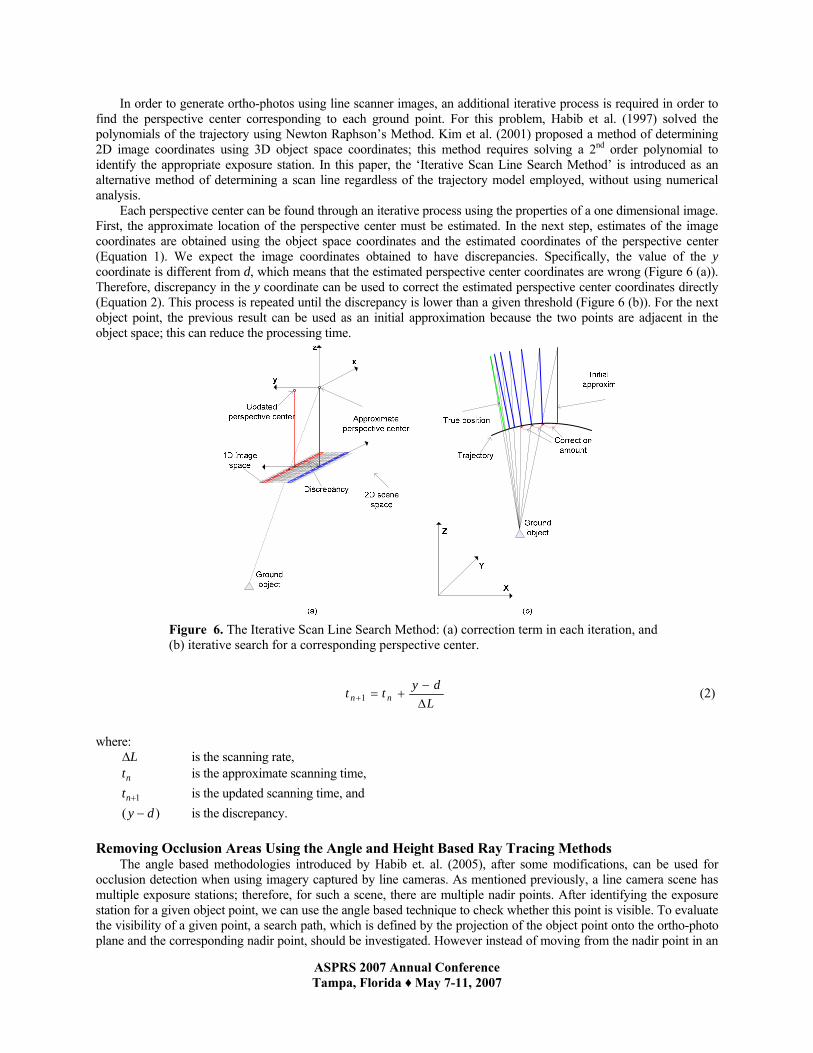
Each perspective center can be found through an iterative process using the properties of a one dimensional image. First, the approximate location of the perspective center must be estimated. In the next step, estimates of the image coordinates are obtained using the object space coordinates and the estimated coordinates of the perspective center (Equation 1). We expect the image coordinates obtained to have discrepancies. Specifically, the value of the y coordinate is different from d, which means that the estimated perspective center coordinates are wrong (Figure 6 (a)). Therefore, discrepancy in the y coordinate can be used to correct the estimated perspective center coordinates directly (Equation 2). This process is repeated until the discrepancy is lower than a given threshold (Figure 6 (b)). For the next object point, the previous result can be used as an initial approximation because the two points are adjacent in the object space; this can reduce the processing time.
Figure 6. The Iterative Scan Line Search Method: (a) correction term in each iteration, and (b) iterative search for a corresponding perspective center.
Ldytt nn ∆
−+=+1 (2)
where:
L∆ is the scanning rate, nt is the approximate scanning time,
1+nt is the updated scanning time, and )( dy − is the discrepancy.
Removing Occlusion Areas Using the Angle and Height Based Ray Tracing Methods
The angle based methodologies introduced by Habib et. al. (2005), after some modifications, can be used for occlusion detection when using imagery captured by line cameras. As mentioned previously, a line camera scene has multiple exposure stations; therefore, for such a scene, there are multiple nadir points. After identifying the exposure station for a given object point, we can use the angle based technique to check whether this point is visible. To evaluate the visibility of a given point, a search path, which is defined by the projection of the object point onto the ortho-photo plane and the corresponding nadir point, should be investigated. However instead of moving from the nadir point in an

ASPRS 2007 Annual Conference Tampa, Florida ♦ May 7-11, 2007
outward direction, the search should start from the object point, and should proceed inward toward the corresponding nadir point. In this case, if the angle (α) along the search path (shown in Figure 7) exceeds the angle α for the point in question, then this point is deemed invisible. For example, in Figure 7, α1 and α2 are the angles of points 1 and 2 along the search path, and α0 is the angle of the projected ray associated with the point under examination. Using these angles, we can determine the visibility of the point in question. If the angle of a point along the search path is larger than the projected ray’s angle, the selected point is marked as invisible. However, the angle based method is computationally expensive. Therefore, we propose an alternative methodology that is more computationally efficient.
In this study, a method called the height based ray tracing method is proposed for removing occlusion areas. The basic principle of height based ray tracing is that, if a certain object point has been successfully captured by the cameras or scanners, then no point along the search path will be higher than the projection ray. Here, the projection ray is a ray of light from the perspective center to the ground object, and the search path is the footprint of this ray projected onto the object space (Figure 7).
To determine whether each pixel selected is visible in an ortho-photo, the height of the ray is compared to the point’s height value along the search path in the ground space. The height of the ray can be simply and reliably calculated using 0Z and Z∆ , which is obtained using the slope of the projection ray and the given interval between the points along the search path (Figure 7). If any point along the search path is higher than the projection ray, then the target point in the DSM is obstructed.
Figure 7. Angle and height based ray tracing methods for removing occlusion areas.
In this procedure, the horizontal positions of the points to be examined along the search path are determined by a
given regular interval, and the procedure continues until one of the following conditions are satisfied: (1) the height of the ray path is higher than Zmax, the maximum value of the given DSM, or (2) the horizontal position of a point along the search path reaches the nadir point in the object space.
Unlike the z-buffer method and the modified z-buffer method, the source image resolution is not an issue in the angle and height based ray tracing methods because only ground points and perspective centers are used to search for the occlusion areas. Therefore, the proposed method produces relatively clear boundaries and occlusion areas, and there are few points falsely categorized as invisible in the resultant images, when compared with the z-buffer method and the modified z-buffer method.
Occlusion Area Recovery
To remove ghost images, occlusion area detection methods are applied using DSMs and source images. In the next step, we consider the recovery of the lost information. If there is no additional information, such as existing ortho-photos and supplementary images, the lost information in the occlusion areas cannot be recovered using given data
ASPRS 2007 Annual Conference Tampa, Florida ♦ May 7-11, 2007
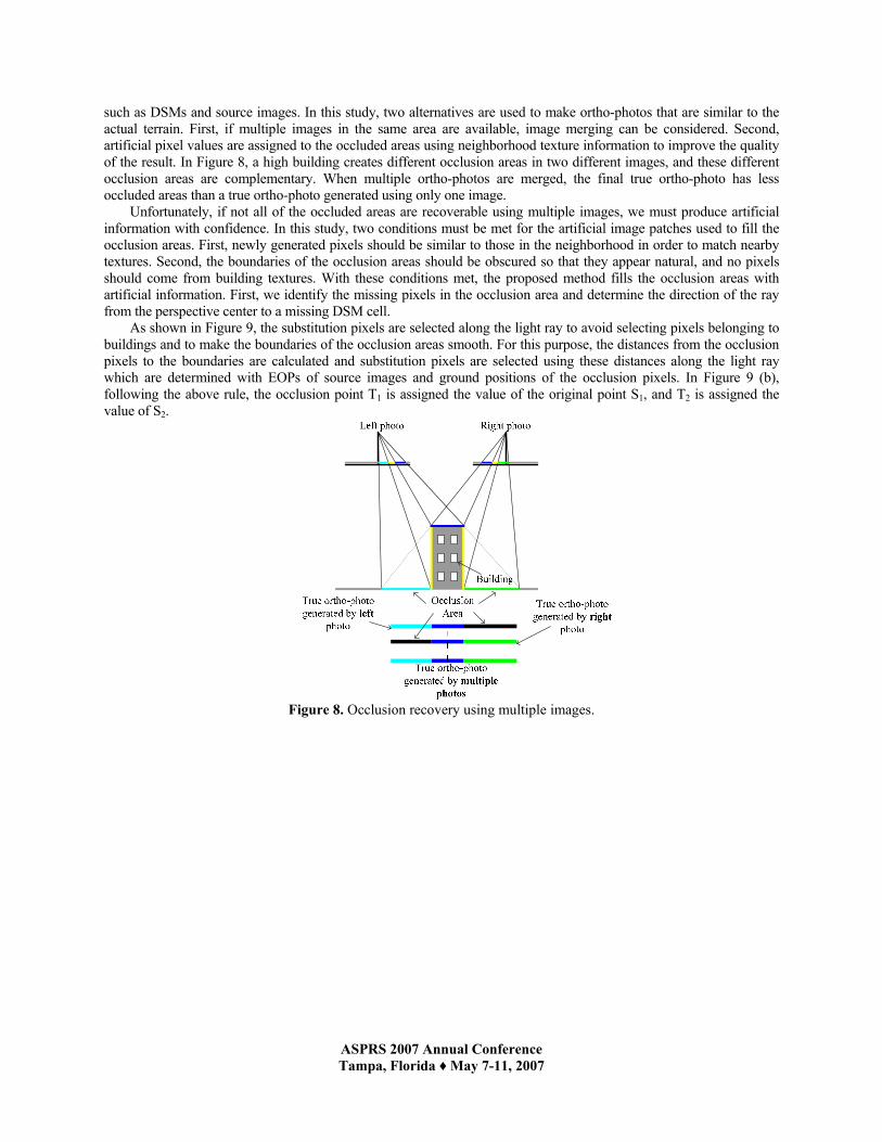
such as DSMs and source images. In this study, two alternatives are used to make ortho-photos that are similar to the actual terrain. First, if multiple images in the same area are available, image merging can be considered. Second, artificial pixel values are assigned to the occluded areas using neighborhood texture information to improve the quality of the result. In Figure 8, a high building creates different occlusion areas in two different images, and these different occlusion areas are complementary. When multiple ortho-photos are merged, the final true ortho-photo has less occluded areas than a true ortho-photo generated using only one image.
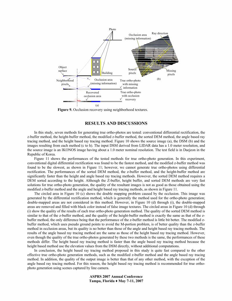
Unfortunately, if not all of the occluded areas are recoverable using multiple images, we must produce artificial information with confidence. In this study, two conditions must be met for the artificial image patches used to fill the occlusion areas. First, newly generated pixels should be similar to those in the neighborhood in order to match nearby textures. Second, the boundaries of the occlusion areas should be obscured so that they appear natural, and no pixels should come from building textures. With these conditions met, the proposed method fills the occlusion areas with artificial information. First, we identify the missing pixels in the occlusion area and determine the direction of the ray from the perspective center to a missing DSM cell.
As shown in Figure 9, the substitution pixels are selected along the light ray to avoid selecting pixels belonging to buildings and to make the boundaries of the occlusion areas smooth. For this purpose, the distances from the occlusion pixels to the boundaries are calculated and substitution pixels are selected using these distances along the light ray which are determined with EOPs of source images and ground positions of the occlusion pixels. In Figure 9 (b), following the above rule, the occlusion point T1 is assigned the value of the original point S1, and T2 is assigned the value of S2.
Figure 8. Occlusion recovery using multiple images.
ASPRS 2007 Annual Conference Tampa, Florida ♦ May 7-11, 2007
Occlusion area (missing information)
Photo
Building
True ortho-photo with missing information
Neighborhood pixels
Recovered occlusion area
True ortho-photo with occlusion
recovery
T2
S2
(a)
(b)
Ray directionOcclusion area (missing information)
Missing pixels
Source pixels
Object surface
T1
S1
Figure 9. Occlusion recovery using neighborhood textures.
RESULTS AND DISCUSSIONS
In this study, seven methods for generating true ortho-photos are tested: conventional differential rectification, the z-buffer method, the height-buffer method, the modified z-buffer method, the sorted DEM method, the angle based ray tracing method, and the height based ray tracing method. Figure 10 shows the source image (a), the DSM (b) and the images resulting from each method (c to h). The input DSM derived from LIDAR data has a 1.0 meter resolution, and the source image is an IKONOS image having about a 1.0 meter nominal resolution. The test field is in Daejeon in the Republic of Korea.
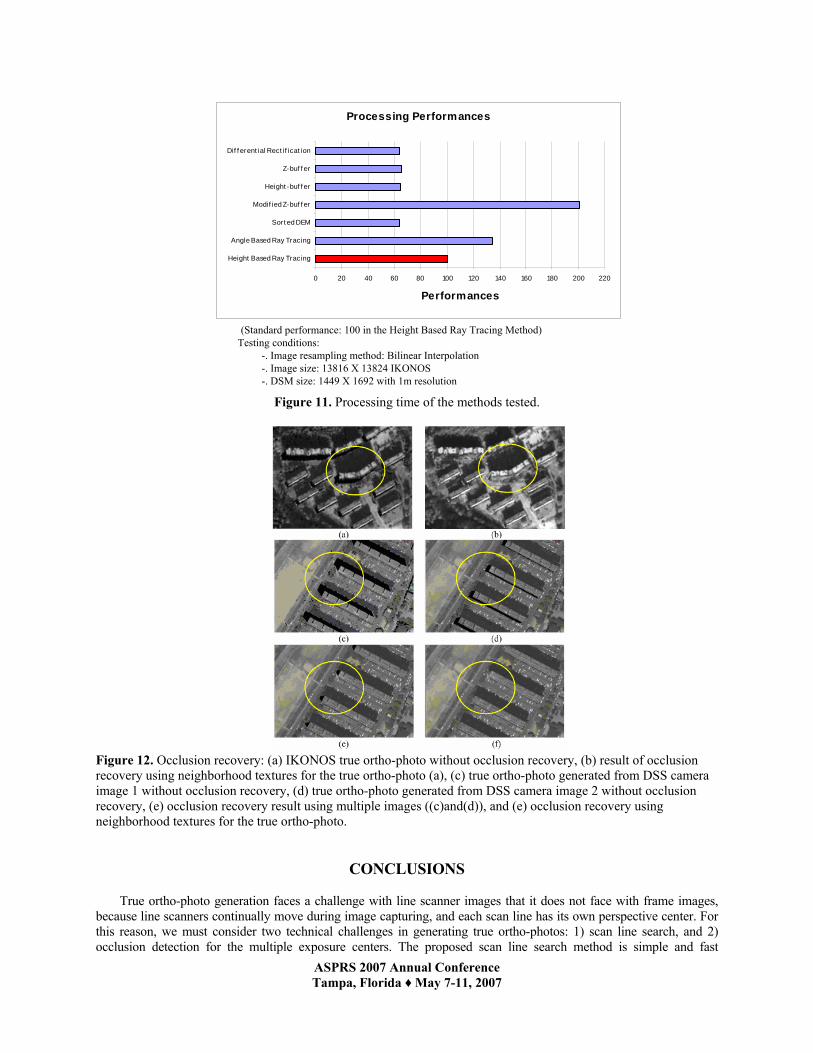
Figure 11 shows the performances of the tested methods for true ortho-photo generation. In this experiment, conventional digital differential rectification was found to be the fastest method, and the modified z-buffer method was found to be the slowest, as shown in Figure 11; however, we cannot generate true ortho-photos using differential rectification. The performances of the sorted DEM method, the z-buffer method, and the height-buffer method are significantly faster than the height and angle based ray tracing methods. However, the sorted DEM method requires a DEM sorted according to the height. Although the Z-buffer, height buffer, and sorted DEM methods are very fast solutions for true ortho-photo generation, the quality of the resultant images is not as good as those obtained using the modified z-buffer method and the angle and height based ray tracing methods, as shown in Figure 11.
The circled area in Figure 10 (c) shows the double mapping problem caused by the occlusion. This image was generated by the differential rectification method, which is generally the method used for the ortho-photo generation; double-mapped areas are not considered in this method. However, in Figure 10 (d) through (i), the double-mapped areas are removed and filled with black color instead of false image textures. The circled areas in Figure 10 (d) through (i) show the quality of the results of each true ortho-photo generation method. The quality of the sorted DEM method is similar to that of the z-buffer method, and the quality of the height-buffer method is exactly the same as that of the z-buffer method, the only difference being that the performance of the z-buffer method is little bit better. The modified z-buffer method, which uses pseudo ground points to avoid the M-portion problem, is of better quality than the z-buffer method in occlusion areas, but its quality is no better than those of the angle and height based ray tracing methods. The results of the angle based ray tracing method are the same as those of the height based ray tracing method. However, even though the quality of the true ortho-photos generated by these two methods is the same, the performances of these methods differ. The height based ray tracing method is faster than the angle based ray tracing method because the height based method use the elevation values from the DSM directly, without additional computations.
In conclusion, the height based ray tracing method proposed in this study is quite fast compared to the other effective true ortho-photo generation methods, such as the modified z-buffer method and the angle based ray tracing method. In addition, the quality of the output image is better than that of any other method, with the exception of the angle based ray tracing method. For this reason, the height based ray tracing method is recommended for true ortho-photo generation using scenes captured by line camera.

ASPRS 2007 Annual Conference Tampa, Florida ♦ May 7-11, 2007
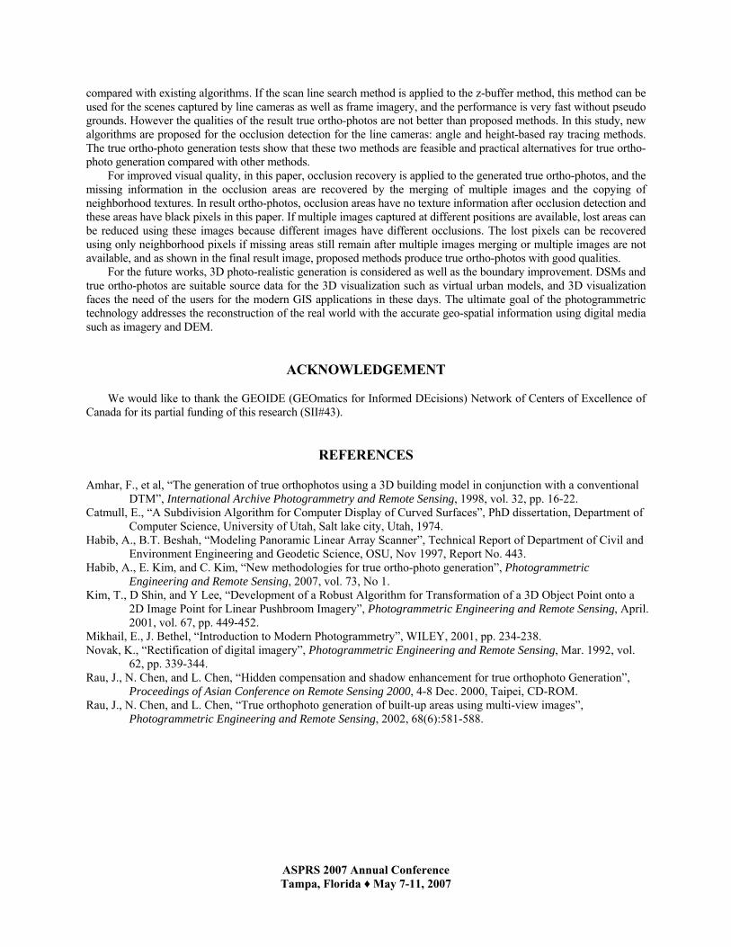
In this study, occlusion recovery is tested; the results are shown in Figure 12. As mentioned previously, we introduce two methodologies: the merging of multiple images, and the copying of neighborhood textures. Figure 12 (a) is the true ortho-photo generated by the height based ray tracing using one image; the circled areas in this figure are the occlusion areas. The missing information is recovered in Figure 12 (b); neighborhood textures are used adaptively to recover the occlusion areas. Occlusion areas in high resolution satellite images are small compared with those in large format frame camera images. For the feasibility test of occlusion area recovery, frame camera images were used, and these results are shown in Figure 12 (c), (d), (e) and (f). Figures (c) and (d) are the true ortho-photos generated using the height based ray tracing method with two frame camera images captured in different positions. These two ortho-photos are complementary because the two frame images have different occlusion areas. The image of Figure 12 (e) is derived from figures (c) and (d) and its occlusion areas are quite small compared with those of the source true ortho-photos. However, we can still find occluded areas in Figure 12 (e), and these areas are recovered using neighborhood textures in the final step. The final images, Figures 12 (b) and (f), show the feasibility of the occlusion recovery method introduced in this paper for line camera and frame camera images.
Figure 10. Test data and results: (a) source image, (b) input DSM, (c) result of conventional digital differential rectification, (d) result of z-buffer method, (e) result of height-buffer method, (f) result of modified z-buffer method, (g) result of sorted DEM method, (h) result of angle based ray tracing method, and (i) result of height based ray tracing method.
ASPRS 2007 Annual Conference Tampa, Florida ♦ May 7-11, 2007
(Standard performance: 100 in the Height Based Ray Tracing Method)Testing conditions:
-. Image resampling method: Bilinear Interpolation-. Image size: 13816 X 13824 IKONOS-. DSM size: 1449 X 1692 with 1m resolution
Processing Performances
0 20 40 60 80 100 120 140 160 180 200 220
Height Based Ray Tracing
Angle Based Ray Tracing
Sort ed DEM
Modif ied Z-buf f er
Height -buf f er
Z-buf f er
Dif f erent ial Rect if icat ion
Performances
Figure 11. Processing time of the methods tested.
Figure 12. Occlusion recovery: (a) IKONOS true ortho-photo without occlusion recovery, (b) result of occlusion recovery using neighborhood textures for the true ortho-photo (a), (c) true ortho-photo generated from DSS camera image 1 without occlusion recovery, (d) true ortho-photo generated from DSS camera image 2 without occlusion recovery, (e) occlusion recovery result using multiple images ((c)and(d)), and (e) occlusion recovery using neighborhood textures for the true ortho-photo.
CONCLUSIONS
True ortho-photo generation faces a challenge with line scanner images that it does not face with frame images, because line scanners continually move during image capturing, and each scan line has its own perspective center. For this reason, we must consider two technical challenges in generating true ortho-photos: 1) scan line search, and 2) occlusion detection for the multiple exposure centers. The proposed scan line search method is simple and fast
ASPRS 2007 Annual Conference Tampa, Florida ♦ May 7-11, 2007
compared with existing algorithms. If the scan line search method is applied to the z-buffer method, this method can be used for the scenes captured by line cameras as well as frame imagery, and the performance is very fast without pseudo grounds. However the qualities of the result true ortho-photos are not better than proposed methods. In this study, new algorithms are proposed for the occlusion detection for the line cameras: angle and height-based ray tracing methods. The true ortho-photo generation tests show that these two methods are feasible and practical alternatives for true ortho-photo generation compared with other methods.
For improved visual quality, in this paper, occlusion recovery is applied to the generated true ortho-photos, and the missing information in the occlusion areas are recovered by the merging of multiple images and the copying of neighborhood textures. In result ortho-photos, occlusion areas have no texture information after occlusion detection and these areas have black pixels in this paper. If multiple images captured at different positions are available, lost areas can be reduced using these images because different images have different occlusions. The lost pixels can be recovered using only neighborhood pixels if missing areas still remain after multiple images merging or multiple images are not available, and as shown in the final result image, proposed methods produce true ortho-photos with good qualities.
For the future works, 3D photo-realistic generation is considered as well as the boundary improvement. DSMs and true ortho-photos are suitable source data for the 3D visualization such as virtual urban models, and 3D visualization faces the need of the users for the modern GIS applications in these days. The ultimate goal of the photogrammetric technology addresses the reconstruction of the real world with the accurate geo-spatial information using digital media such as imagery and DEM.
ACKNOWLEDGEMENT
We would like to thank the GEOIDE (GEOmatics for Informed DEcisions) Network of Centers of Excellence of Canada for its partial funding of this research (SII#43).
REFERENCES
Amhar, F., et al, “The generation of true orthophotos using a 3D building model in conjunction with a conventional DTM”, International Archive Photogrammetry and Remote Sensing, 1998, vol. 32, pp. 16-22.
Catmull, E., “A Subdivision Algorithm for Computer Display of Curved Surfaces”, PhD dissertation, Department of Computer Science, University of Utah, Salt lake city, Utah, 1974.
Habib, A., B.T. Beshah, “Modeling Panoramic Linear Array Scanner”, Technical Report of Department of Civil and Environment Engineering and Geodetic Science, OSU, Nov 1997, Report No. 443.
Habib, A., E. Kim, and C. Kim, “New methodologies for true ortho-photo generation”, Photogrammetric Engineering and Remote Sensing, 2007, vol. 73, No 1.
Kim, T., D Shin, and Y Lee, “Development of a Robust Algorithm for Transformation of a 3D Object Point onto a 2D Image Point for Linear Pushbroom Imagery”, Photogrammetric Engineering and Remote Sensing, April. 2001, vol. 67, pp. 449-452.
Mikhail, E., J. Bethel, “Introduction to Modern Photogrammetry”, WILEY, 2001, pp. 234-238. Novak, K., “Rectification of digital imagery”, Photogrammetric Engineering and Remote Sensing, Mar. 1992, vol.
62, pp. 339-344. Rau, J., N. Chen, and L. Chen, “Hidden compensation and shadow enhancement for true orthophoto Generation”,
Proceedings of Asian Conference on Remote Sensing 2000, 4-8 Dec. 2000, Taipei, CD-ROM. Rau, J., N. Chen, and L. Chen, “True orthophoto generation of built-up areas using multi-view images”,
Photogrammetric Engineering and Remote Sensing, 2002, 68(6):581-588.