Embed Size (px)
Citation preview

Comparative Analysis of MEMSPiezoelectric Materials for the Designof a Piezotube-Type Pressure Sensor
Sachin Kala, Varij Panwar, Lokesh Panwar and Sushant Sharma
Abstract MEMS-based pressure sensors with high voltage sensitivity can be usedin many areas of MEMS, biomedical, optical displays, automobile, etc. This paperfocuses on the comparison of various types of MEMS piezoelectric materials whichsense and convert the mechanical energy into electrical energy using MEMStechnology. The model designing and working principle of proposed MEMSPiezotube-type pressure sensor is elucidated here. The modeling and simulation ofMEMS Piezotube pressure sensor is done using COMSOL 5.2. The displacement ofpiezoelectric material and induced electric potential analysis are carried out forvarious types of MEMS piezoceramic materials. This paper shows the study ofvoltage generation using direct piezoelectric effect. Here, analysis is done in cen-timeter range making two sets of boundary conditions where internal fluid pressureof various ranges is applied onto MEMS Piezotube-type pressure sensor usingvarious piezoceramic materials. Furthermore, analyses are done with increasedvalue of pressure, but now the pressure is applied externally. The new result showsthat there is a huge increment in induced electric potential on increasing thepressure and dimensions. Indirect piezoelectric effect is also shown in this paper,where on applying the electric field, material becomes strained and strain is directlyproportional to electric field.
Keywords Piezoelectric material � Energy harvesting � MEMS
S. Kala (&) � V. Panwar � L. Panwar � S. SharmaGraphic Era University, Dehradun, Indiae-mail: [email protected]
V. Panware-mail: [email protected]
© Springer Nature Singapore Pte Ltd. 2018R. Singh et al. (eds.), Intelligent Communication, Control and Devices,Advances in Intelligent Systems and Computing 624,https://doi.org/10.1007/978-981-10-5903-2_160
1537

1 Introduction
Today tremendous development has been shown in field of MEMS (microelec-tromechanical system) in field of energy harvesting. Nowadays various pressuresensor applications have been developed based on MEMS technology which isbeneficial to automotive, biomedical, and optical displays, consumer products,fluidics, etc. Conventional pressure sensors were used before, but now these MEMSsensors are mostly used due to their smart function, reliability; they occupy lessspace, low weight, and low cost [1]. Piezoelectric thin film has been widely used invarious MEMS applications such as in pressure sensors, biomedical, and energyharvesting [2, 3]. Many researchers have used piezoceramic sheet elements assensors in controllable structure systems, health monitoring applications [5], [6] aswell as in energy harvesting applications [7]. They are used in sensor andactuators to convert mechanical energy into electrical energy and vice versa.7S. M. Peelamedu et al. [4] have used lead zirconate titanate (PZT-5H) as apiezoelectric material in their paper where they had illustrated the inverse piezo-electric effect and the direct piezoelectric effect using piezoceramic tube. Here,comparisons are shown for various piezoelectric materials used in this sensor.Section one deals with different results in terms of displacement and inducedelectric potential when different internal pressure is applied on materials. Finally,comparisons of all piezoceramic materials are made, in which the PZT-7A andbarium titanate have highest output voltage of about 2 and 2.8 V, respectively,among all other materials. Section two deals with different results in terms ofdisplacement and induced electric potential when increased external pressure isapplied on piezoceramic materials. The results are shown in Table 7, and a hugeincrement in induced electric potential with increase in pressure and dimensions canbe seen there. Hence, this pressure sensor can be widely used in energy harvestingapplications. In section three, indirect piezoelectric effect is shown, where onapplying the electric field, material becomes strained and strain is directly pro-portional to electric field. Here, it is found out that PZT-5H shows maximumdisplacement when potential difference of one volt is applied across it.
1.1 Equation
Piezoceramics are transversely isotropic materials. The piezoelectric constitutive lawis defined by two equations shown below. Their combined form in strain-chargeform is
S ¼ sET þ dE: ð1Þ
D ¼ dT þ2TE: ð2Þ
1538 S. Kala et al.

The matrix form of direct piezoelectric effect is shown in Eq. 2, whereas Eq. 1shows the matrix form of converse piezoelectric effect, where the electric chargedisplacement components are represented by (D), strain components are representedby (S), field variables are the stress components represented by (T), dielectric constantis denoted by (d), and electric field components are denoted by (E) in Eqs. 1 and 2.
The electric displacement (D) is shown in Eq. 3
D ¼2o2r Eþ dX: ð3Þ
P ¼ dX: ð4Þ
where the electric displacement field is denoted by (D), the electric polarization isdenoted by (P), and the electric field is denoted by (E). For more information aboutpiezoelectric sensors refer [9].
2 Sensor Design
The modeling and simulation of pressure sensor is explained in this section.Recently, different transduction methods such as capacitive, thermal transduction,piezoelectric and piezoresistive are explored; each method has their own merits anddemerits over each other [10, 11]. The paper shows the static 2D axisymmetricanalysis of a piezoelectric actuator utilizing different piezoelectric materials usingCOSMOL Multiphysics 5.2. A modeling and simulation of radially polarizedpiezoelectric tube is presented where the direct piezoelectric method is shown. Inpiezoelectric materials, the negative and positive charges are symmetrically dis-tributed in a crystal. When the pressure is applied on piezoelectric material, itresults in formation of the positive charge on the compressed side and the negativecharge on the expanded side. On removing the applied pressure, net current flowsacross the material; this is called as direct piezoelectric method. For case one, theheight, inner radius, and outer radius of tube are defined as 3, 4, and 6 cm,respectively, shown in Fig. 1 (radius taken same as of human wrist). In case two,the height, inner radius, and outer radius of piezotube remain same, but the pressureis now applied externally with an increased value of range 80 psi or 551.581 kPa.
3 Simulation of MEMS Piezotube Pressure Sensor
The results of a MEMS Piezotube pressure sensor are presented in this section. Theinternal fluid pressure is applied to piezoelectric material in the range of 11 to19 kPa. The normal blood pressure (systolic pressure) of human body is 19 kPa,and lower blood pressure (diastolic) is taken as 11 kPa approximately. Thedeformation, displacement, and induced voltage sensitivity vary from material to
Comparative Analysis of MEMS Piezoelectric Materials … 1539

material depending on their properties. This MEMS pressure sensor is designedusing COSMOL Multiphysics 5.1. Figure 2a, b shows the 3D view of displacementand induced electric potential, respectively, when the pressure is applied internally.
The deformation, displacement, and induced voltage sensitivity vary accordingto the property of material. In second case, the pressure is applied externally and itsvalue is taken as 80 psi or 551.581 kPa which is same as that is applied on normal
Fig. 1 Geometrical dimensions of MEMS Piezotube-type pressure sensor in centimeter (cm)
Fig. 2 a 3D displacement view of MEMS Piezotube-type pressure sensor when the pressure isapplied internally. b 3D view of induced electric potential when the pressure is applied internally
1540 S. Kala et al.

cycle tires. Now, every time tire rotates piezomaterial inside it gets deformed.Figure 3a, b shows the 3D view of displacement and induced electric potential,respectively, when the pressure is applied externally.
4 Indirect Piezoelectric Effect
Here, in this section, the height, inner radius, and outer radius of tube are defined as3, 4, and 6 cm, respectively, shown in Fig. 1. When the potential difference of onevolt is applied to various piezoceramic materials, they get strained (deform) and thestrain is directly proportional to the electric field shown in Fig. 4b. The piezo-electric material expands or contracts depending upon the applied voltage. Whenthe applied voltage has the same polarity as poling voltage, then material expands
Fig. 3 a 3D displacement view when the pressure is applied externally. b 3D view of inducedelectric potential when the pressure is applied externally
Fig. 4 a 2D displacement view of MEMS Piezotube-type pressure sensor when the potentialdifference of one volt is applied. b 3D view of MEMS Piezotube-type pressure sensor when thepotential difference of 1 V is applied
Comparative Analysis of MEMS Piezoelectric Materials … 1541

otherwise gets contracts when the applied voltage has opposite polarity that ofpoling voltage. The 2D and 3D view of displacement and electric potentialof pressure sensor are shown in Fig. 4a, b, respectively, when potential differenceof one volt is applied across it. The result analyses done in terms of displacementfor various piezoelectric materials are shown in Table 8.
5 MEMS Material Analysis for Pressure Sensor
COSMOL Multiphysics 5.1 version provides us various materials. They can beaccessed from the material library. But only few MEMS material can be used due toproblems that occur during time of microfabrication. Mac Donald [8] has identifiedthat there should be three basic properties of the materials that we are going to usein MEMS technology which are as follows: (a) material must be suitable withsemiconductor fabrication technology, (b) material should have good mechanicaland electrical properties, (c) intrinsic properties that slow down the rise of highstresses during processing. When the mechanical load, stress, and vibrations areapplied on piezomaterials, it results in evolution of piezoelectric, electromagnetic,and electrostatic energies which can be used in harvesting [5]. The study of 5MEMS piezoceramic materials is shown here one by one. The overall results areexplained on the basis of displacement and induced electric potential of eachmaterial.
5.1 Lead Zirconate Titanate (PZT-5H)
It belongs to special class of orthotropic materials. We can use it in either zy-planematerial orientation or the zx-plane material orientation; the results show that bothplanes give the same solution; it is because of its transversely isotropic nature.Piezoceramic materials show the same properties or characteristics when lie in oneplane, but their properties show sudden changes when they lie in the directionnormal to this plane. It has very high coupling coefficient, piezoelectric chargecoefficient, and permittivity and hence used for low-power applications where theseproperties are required. It is the most suitable piezoelectric material for imagingapplications, level sensors, field sensors, actuator and accelerometers. Table 1shows some of its material properties.
Table 1 Material propertiesof PZT-5H
S. No. Material property Value Units
1 Density 7500 kg/m3
2 Poisson ratio 0.34 1
3 Dielectric constant 3400 1
1542 S. Kala et al.

It is used as a piezoelectric material in a piezotube pressure sensor. Figure 5shows the value of simulated result on induced electric potential, which isabout 1 V.
5.2 Lead Zirconate Titanate (PZT-5A)
It is used in low-power applications where high dielectric constant, volume resis-tivity, high voltage sensitivity, and stability in high temperature ranges are required.It is a piezoceramic material (transversely isotropic) and an excellent source ofmaterial for piezo igniters, probes, sensors, and in biomedical areas. Table 2 showssome of its material properties.
It is used as a piezoelectric material in a piezotube pressure sensor. Figure 6shows the value of simulated result on induced electric potential, which is about1.3 V.
5.3 Lead Zirconate Titanate (PZT-7A)
It is a piezoceramic material (transversely isotropic). This is used in high-powerapplications where high coercive field, low dielectric losses, high driving field, and
Fig. 5 Plot of electricpotential for lead zirconatetitanate (PZT-5H)
Table 2 Material propertiesof PZT-5H
S. No. Material property Value Units
1 Density 7750 kg/m3
2 Poisson ratio 0.35 1
3 Dielectric constant 1800 1
Comparative Analysis of MEMS Piezoelectric Materials … 1543

high electromechanical coupling coefficient properties are needed. This is mostlysuited for high-power electroacoustic devices, generators, equipments, etc. Table 3shows some of its material properties.
It is used as a piezoelectric material in a piezotube pressure sensor. Figure 7shows the value of simulated result on induced electric potential, which is about2 V.
5.4 Lead Zirconate Titanate (PZT-2)
It is a piezoceramic material (transversely isotropic). We can use it either in the zx-plane material orientation or in the zy-plane material orientation; both give the samesolution. It has very high coupling coefficient, piezoelectric charge coefficient, andpermittivity and hence used for low-power applications where these properties arerequired. Table 4 shows some of its material properties.
It is used as a piezoelectric material in a piezotube pressure sensor. Figure 8shows the value of simulated result on induced electric potential, which is about1.8 V.
Fig. 6 Plot of electricpotential for lead zirconatetitanate (PZT-5A)
Table 3 Material propertiesof PZT-7A
S. No. Material property Value Units
1 Density 7700 kg/m3
2 Poisson ratio 0.35 1
1544 S. Kala et al.
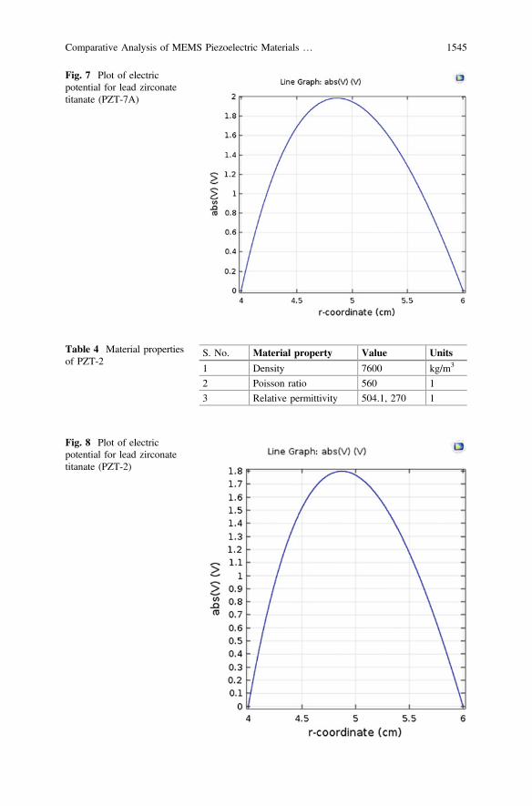
Fig. 7 Plot of electricpotential for lead zirconatetitanate (PZT-7A)
Table 4 Material propertiesof PZT-2
S. No. Material property Value Units
1 Density 7600 kg/m3
2 Poisson ratio 560 1
3 Relative permittivity 504.1, 270 1
Fig. 8 Plot of electricpotential for lead zirconatetitanate (PZT-2)
Comparative Analysis of MEMS Piezoelectric Materials … 1545

5.5 Barium Titanate
Barium titanate (BaTiO3) is an inorganic compound. It is a ferroelectric ceramicpowder white in color and becomes transparent as grows in larger crystals. Thispiezoelectric material is used in microphones, sensors, and other transducers.Before it was used as a major source of piezoelectric material, but afterward leadzirconate titanate (PZT) takes its place and replaced it massively. Table 5 showssome of its material properties.
It is used as a piezoelectric material in a piezotube pressure sensor. Figure 9shows the value of simulated result on induced electric potential, which is about2.8 V.
Table 5 Material propertiesof barium titanate
S. No. Material property Value Units
1 Density 7600 kg/m3
2 Relative permittivity 1976.8, 111.7 1
3 Young modulus 67 GPa
Fig. 9 Plot of electricpotential for barium titanate(BaTiO3)
1546 S. Kala et al.

6 Overall Comparison of Materials
Different piezoelectric materials were used in this sensor. Their design and simu-lations are done for internal pressure range of about 11–19 kPa in case one andexternal pressure of about 80 psi or 551.581 kPa in case two. Their analysis wascarried out one by one using COSMOL 5.2. The displacement and the inducedelectric potential vary material to material depending on their properties. In caseone, result shows that the PZT-7A and barium titanate as a piezoelectric materialhave the highest value of induced electric potential of 2 and 2.8 V, respectively,among the all other materials. In case two, analyses are done with increased valueof pressure up to 80 psi or 551.581 kPa, which is generally taken same as that of acycle tire pressure and now the pressure is applied externally. The new result showsthat there is a huge increment in induced electric potential on increasing thepressure and dimensions. Case three deals with indirect piezoelectric effect, whereon applying the electric field, material becomes strained and strain is directlyproportional to electric field. Here, it is found out that PZT-5H shows maximumdisplacement when potential difference of one volt is applied across it. The resultsand analysis of different materials and their comparisons are shown in Tables 6, 7,and 8, respectively.
Table 6 Comparative analysis of MEMS piezoelectric materials when the pressure is appliedinternally
S. No. Materialproperty
Displacementin nm, when11 kPapressure isapplied
Electric potentialgenerated in volts,when 11 kPapressure is applied
Displacementin nm, when19 kPapressure isapplied
Electric potentialgenerated in voltswhen 19 kPapressure is applied
1 pzt-5h 22.5 0.6 39.5 1
2 pzt-5a 22 0.75 38 1.3
3 pzt-7a 14.4 1.1 25 2
4 pzt-2 15.6 1 27 1.8
5 Bariumtitanate
11.8 1.6 20.2 2.8
Comparative Analysis of MEMS Piezoelectric Materials … 1547

7 Conclusion
The complete study of different MEMS piezoelectric materials used in sensor hasbeen done, and their simulated results are shown in Tables 6, 7, and 8, respectively,where results conclude that for the pressure range of about 11–19 kPa, PZT-7A andbarium titanate have the highest electric potential sensitivity among all. Forapplication purpose, this pressure sensor can be used in biomedical, automobile,and many other areas. The radius of piezotube is taken as same as the human wristso it can be used in blood pressure measurements. The normal blood pressure(systolic pressure) of human body is 19 kPa and lower blood pressure (diastolic) istaken as 11 kPa approximately. Hence, this tube-shaped pressure sensor can be
Table 7 Comparative analysis of MEMS piezoelectric materials when the pressure is appliedexternally
S. No. Materialproperty
Displacement in nm when80 psi or 551.581 kPapressure is applied
Electric potential generated involts when 80 psi or 551.581 kPapressure is applied
1 Leadzirconatetitanate(PZT-5H)
1160 36
2 Leadzirconatetitanate(PZT-5A)
1190 45
3 Leadzirconatetitanate(PZT-7A)
785 70
4 Leadzirconatetitanate(PZT-2)
850 60
5 Bariumtitanate
550 90
Table 8 Comparative analysis of MEMS piezoelectric materials when potential difference of 1 Vis provided across it (indirect piezoelectric effect)
S. No. Material property Displacement in nm
1 Lead zirconate titanate (PZT-5H) 0.95
2 Lead zirconate titanate (PZT-5A) 0.6
3 Lead zirconate titanate (PZT-7A) 0.22
4 Lead zirconate titanate (PZT-2) 0.22
5 Barium titanate 0.125
1548 S. Kala et al.

used as watches to give out blood pressure measurements in terms of voltagewhenever the pulses are pressed with the help of piezoelectric material. Using thisas an internal fluid pressure, results have been evaluated. In case two, piezoelectricpressure sensors can be used in between tube and tires of cycles, bicycles, auto-mobiles, etc, as an energy harvesting application. Whenever tire rotates, piezo-material inside it gets deformed that results in voltage generation; this pressuresensor can be used in many fields such as biomedical, automobile platforms wherewhenever this pressure sensor gets deformed it results in voltage generation. In casethree, the study of indirect piezoelectric effect is done, where it is shown that thelead zirconate titanate (PZT-5H) has maximum displacement of about 0.95 nmamong all other piezoceramic materials, when one volt of potential difference isapplied across it. These piezoelectric materials are pollution-free, save fossil fuels,and are completely natural sources of energy. So we should use them in ourday-to-day life as energy harvesting applications.
References
1. L. Lin and W. Yun, “MEMS Pressure Sensors for Aerospace Applications,” Proceeding IEEEAerospace Conference, vol. 1, Colorado, 21–28, pp. 429–436, March 1998.
2. D. L. DeVoe and A. P. Pisano A P 2001 “Surface micromachined piezoelectricaccelerometers (PiXLs)”, J. Microelectromech. Syst 10, pp. 180–6, 2001.
3. P. Muralt P, “Piezoelectric micromachined ultrasonic transducers based on PZT thin films”,IEEE Trans. Ultrason. Ferroelectr. Freq. Control 52, 2276–88, 2006.
4. S. M. Peelamedu et al. (Proceedings of the Institution of Mechanical Engineers, Part I: Journalof Systems and Control Engineering March 1, 2000 vol. 214 no. 2 87–97).
5. J. Sirohi and I. Chopra, “Fundamental understanding of piezoelectric strain sensors,” J. Intell.Mater. Syst. Smart Struct., vol. 11, pp. 246–257, Apr. 2000.
6. H. A. Tinoco, A. L. Serpa, and A. M. Ramos, “Numerical study of the effects of bonding layerproperties on electrical signatures of piezoelectric sensors,” Mecánica Comput., vol. 29, no.86, pp. 8391–8409, Nov. 2010.
7. A. E. Kubba and K. Jiang, “Efficiency enhancement of a cantileverbased vibration energyharvester,” Sensors, vol. 14, no. 1, pp. 188–211,2014.
8. MacDonald N C, Chen L Y, Yao J J, Zhang Z L, McMillan J A, Thomas D C &Haselton K R, “Sensors and Actuators”, 20, (1989)19.
9. IEEE Standard on Piezoelectricity, ANSI/IEEE Standard 176, 1987.10. A. Aini, A.N Nordin, H. Salleh, “A comparative study on MEMS piezoelectric microgen-
erators,” Microsyst Technol, 2010.11. S. P. Beeby, M. J. Tudor and N. M. White, “Energy harvesting vibration sources for
microsystems applications.” Meas. Sci. Technol. 2006; 17:R175–R195.
Comparative Analysis of MEMS Piezoelectric Materials … 1549