Embed Size (px)
Citation preview
International Journal of Advance Research In Science And Engineering http://www.ijarse.com
IJARSE, Vol. No.3, Issue No.8, August 2014 ISSN-2319-8354(E)
37 | P a g e www.ijarse.com
COMPARATIVE STUDY OF PERFORMANCE BASED
PLASTIC DESIGN OF R.C AND COMPOSITE (CFRST)
MOMENT RESISTING FRAMES BASED ON INELASTIC
RESPONSE ANALYSIS
1G.S.Hiremath
2Kushappa M Kabade
1Professor,
2Post Graduate Student, Civil Engineering Department,
Basaveshwar Engineering College, Bagalkot-587102, (India)
ABSTRACT
Performance based plastic design method has emerged as a most promising and efficient seismic design method
which explicitly accounts for the inelastic behavior of structural system in the design process, using the concept of
energy balance applied to a pre-selected target drift and yield mechanism as design criteria based on “strong
column –weak beam concept” with proper strength and ductility. In the present study comparison of a ten-storey
R.C and Composite (CFRST column and Steel beam) moment resisting frames are designed by the PBPD method in
terms of lateral force distribution, and the seismic performance of MRF is evaluated by non-linear static pushover
analysis and non-linear dynamic time history analysis under five different ground motions using the ETABS-2013
software, with user defined hinge properties. From the above studies it is found that for nonlinear static pushover
analysis shows formation of hinges in beams and at the base of the columns only for both frames leading to
increased performance which clearly indicates that the PBPD method gives economical sections in terms of the
optimum capacity utilization, but it is observed that the composite MRF has better yield mechanism compared to
R.C MRF. From the nonlinear time history analysis it has been seen that the ground motions causes larger
displacements and acceleration in the PBPD of Composite frame as compared to R.C frame. Hence it is concluded
that composite moment resisting frame has performed better for high seismicity as compared to R.C moment
resisting frame.
Keywords: Moment Resisting Frame, Performance Based Plastic Design (PBPD), Target Drift Yield
Mechanism, Nonlinear Static Pushover Analysis, Nonlinear Dynamic Time History Analysis,
Performance Point, Acceleration, Displacement.
I. INTRODUCTION
In the recent major earthquakes, it is noticed that the high seismic risk in urban areas is increasing and the
infrastructure facility is far from socio-economically acceptable levels. There is an urgent need of practical design
methods to reverse this situation and it is believed that one of the most promising way and efficient seismic design

International Journal of Advance Research In Science And Engineering http://www.ijarse.com
IJARSE, Vol. No.3, Issue No.8, August 2014 ISSN-2319-8354(E)
38 | P a g e www.ijarse.com
of doing this is through one such complete design methodology, which accounts for inelastic structural performance
directly, has been developed by the senior author and his associates at the University of Michigan the Performance
Based Plastic Design (PBPD) method (Lee and Goel, 2001)[1]
. The methodology used here is direct design method
in which uses pre-selected target drift and yield mechanisms as key performance criteria from the very start,
eliminating or minimizing the need for lengthy iterations to arrive at the final design that determine the degree and
distribution of expected structural damage objectives during an earthquake.
An important and economic combination of construction materials is that of steel and concrete, with applications in
medium to high-rise buildings as well as bridges and steel-concrete composite systems have become quite popular in
recent times because of their advantages against conventional construction. Composite construction combines the
better properties of the both i.e. concrete in compression and steel in tension, results in fast construction. In India, it
is comparatively new and no updated design codes are available for the same.(Anish N. Shah et al)[2]
In a concrete-filled steel tube column (RCFT, CCFT or CFST) the hollow steel tube is filled with concrete, with or
without reinforcing bars. Here, the steel element contributes tensile capacity, provides confinement to concrete
elements, and reduces concrete shrinkage while concrete element prevents steel from premature local buckling so
that both elements contribute to the strength particularly for seismic applications. Application of the CFST concept
may lead to 60% total saving of steel in comparison to a conventional structural steel system (Amir Fam, Frank S.
Qie and Sami Rizkalla Journal Of Structural Engineering, ASCE, April 2004)[3]
.
The use of concrete-filled steel tubular columns (CFTs) in structural frames has increased in United States, Japan,
China and Australia during the past the past two decades. They have been used as columns or bracings in high-rise
buildings, piers for bridges, and so on. Design of CFRST column is incorporated in several codes such as ACI
Building Code (ACI 318-08), Specification for Structural Steel Buildings (AISC-LRFD 360-10), EC 4, AS-5100,
and CSA S16-01, CECS-28:90, AIJ(S. B. Beheshti-Aval) [4]
.
II. ANALYTICAL MODELLING
In the present study 3-dimensional
[5]. Ten-storeyed R.C and Composite (CFSRT) moment resisting frames are
considered. The plan and Elevation of the RC and Composite (CFT) moment resisting frame of ten storey
buildings[6]
is shown in Figure 1 and 2. In this study, the Plan and Elevation is deliberately kept similar for both the
frames to evaluate the Performance based plastic design method. The basement height of 4m and typical storey
height of 3m is kept for all other storey in both the buildings[6]
. The buildings are considered to be located in the
seismic zone-V[5,6]
. For R.C frame material properties used are M-25 grade concrete and Fe415 steel are considered
as per IS:456-2000, For composite frame concrete filled rectangular steel tube column used is as column (CFRST)
of material properties ASTM-A500 GRADE B steel tube, and 4000 psi concrete as per American AISC/LRFD-360-
10 standard. The user defined hinge (M3) assigned at ends of for all floor beams, and P-M2-M3 for columns are
entered as a input in ETABS-2013.
International Journal of Advance Research In Science And Engineering http://www.ijarse.com
IJARSE, Vol. No.3, Issue No.8, August 2014 ISSN-2319-8354(E)
39 | P a g e www.ijarse.com
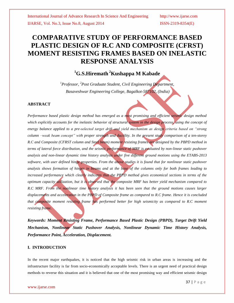
Fig 1. Plan and Elevation of ten-storeyed R.C moment resisting frame
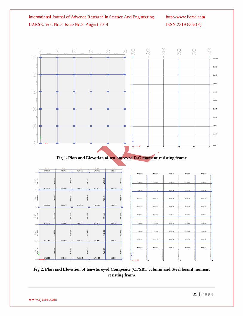
Fig 2. Plan and Elevation of ten-storeyed Composite (CFSRT column and Steel beam) moment
resisting frame

International Journal of Advance Research In Science And Engineering http://www.ijarse.com
IJARSE, Vol. No.3, Issue No.8, August 2014 ISSN-2319-8354(E)
40 | P a g e www.ijarse.com
III. METHODOLOGY OF THE STUDY
A ten-storey R.C and composite moment resisting frames are designed by the Performance based Plastic design
method. Then the frames are analyzed and evaluated by the nonlinear static analysis (Push over Analysis) and
nonlinear dynamic analysis (Time history analysis) under five different ground motions by using ETABS-2013.
Performance based plastic design method [Lee and Goel, 2001]
[1] which is the major part of this study. In order to
achieve the objectives of PBPD i.e. predictable and desired structural response. It is necessary to account for
inelastic behaviour of structures directly in the design process. Figure 3 shows the target drift and yield mechanism
chosen for the frame while designing it using the performance based plastic design method. The plastic hinges are to
be formed at the bottom of the base column and at both ends of all floor beams only as shown in Figure 3. The
beams are modeled to behave inelastically, while the columns are modeled (or „forced‟) to behave elastically. The
seismic parameters considered for PBPD of R.C and Composite MRFs are, Yield drift ratio θy =1%, Target drift
ratio θu=3%, Inelastic drift ratio θp= θu- θy=2%, Ductility factor μs= θu/ θy=3, Reduction Factor due to Ductility
Rμ=2, Energy Modification Factor γ=1.25[5]
Fig 3. Target and Yield mechanism[Lee and Goel, 2001][1]
Table.1 The seismic parameters of both the frames for PBPD method
Natural time Period Tn 0.985 sec
Equivalent time Period Teq 1.797 sec
Inelastic spectral acceleration Sa/g (Ce) 1.38 for R.C medium soil
0.588 Site Class D for composite
Yield drift ratio θy 1%
Target drift ratio θu 3%
Inelastic drift ratio θp= θu- θy 2% Ductility factor μs= θu/ θy 3
Reduction Factor due to Ductility Rμ 2
Energy Modification Factor γ 1.25

International Journal of Advance Research In Science And Engineering http://www.ijarse.com
IJARSE, Vol. No.3, Issue No.8, August 2014 ISSN-2319-8354(E)
41 | P a g e www.ijarse.com
3.1 User Defined Hinges
The definition of user-defined hinge properties requires moment–curvature analysis of each element. For the
problem defined, building deformation is assumed to take place only due to moment under the action of laterally
applied earthquake loads. Moment-curvature values calculated for R.C frame as per IS:456-2000[8]
and for
Composite frame as per AISC/LRFD:360-10[9]
. The user-defined M3 hinge was assigned at ends of the beam
member where flexural yielding is assumed to occur and P-M2-M3 for columns axial force with biaxial moments.
Calculated Moment-curvature values for both MRF are entered as input in ETABS-2013.
3.2 Analysis performed in ETABS 2013
3.2.1 Pushover analysis
Pushover analysis is a nonlinear static method of analysis becoming a popular tool for seismic performance
evaluation of existing and new structures. Pushover analysis can be performed as either force-controlled or
displacement controlled depending on the physical nature of the load and the behaviour expected from the structure.
A two or three dimensional model which includes bilinear or tri linear load-deformation diagrams of all lateral force
resisting elements is first created and gravity loads are applied initially. A predefined lateral load pattern which is
distributed along the building height is then applied and the entire frame is carried out up to the target drift (3%) as
maximum displacement considered at roof level by using design lateral force distribution[5]
. The lateral forces are
increased until some members yield. The structural model is modified to account for the reduced stiffness of yielded
members and lateral forces are again increased until additional members yield. The process is continued until a
control displacement at the top of building reaches a certain level of deformation or structure becomes unstable. The
roof displacement is plotted with base shear to get the global capacity curve. The pushover analysis is carried out as
per FEMA 440[12]
and a main component of Capacity Spectrum Analysis method (ATC-40) [13]
. The internal forces
and deformations computed at the target displacement are used as estimates of inelastic strength and deformation
demands that have to be compared with available capacities for a performance check.
3.2.2 Time History Analysis
The time history analysis is an actual dynamic analysis that can be done for both linear and nonlinear systems. It is
found that this analysis incorporates the real time earthquake ground motions and gives the true picture of the
possible deformation and collapse mechanism in a structure. But, at the same time, it is a very tedious and complex
analysis having a lot of mathematical calculations. Although non-linear dynamic analysis is generally considered to
be the most accurate of the available analysis methods, it is cumbersome for design. This is the most sophisticated
analysis procedure for predicting forces and displacements under seismic input. However, the calculated response
can be very sensitive to the characteristics of the individual ground motion used as seismic input; therefore several

International Journal of Advance Research In Science And Engineering http://www.ijarse.com
IJARSE, Vol. No.3, Issue No.8, August 2014 ISSN-2319-8354(E)
42 | P a g e www.ijarse.com
time-history analyses are required using different ground motion records. This most basic inelastic method at this
time is considered overly complex and impractical for general use.
IV. RESULTS AND DISCUSSION
4.1 Inelastic response analysis of the R.C moment resisting frame designed Using performance
Based Plastic Design Approach
The R.C and Composite MRFs are designed using lateral force distribution along the height of the building for the
Performance Based Plastic Design method and then nonlinear static and time history analyses were carried out. In
nonlinear static pushover analysis, the entire frame is carried out up to the target drift (3% of total height of the
building) by using design lateral force distribution and therefore the failure caused is shown in below Figure-4
Fig 4. Formation of Plastic hinges at step 7 and 8 in the R.C frame designed using PBPD approach
It has been clearly seen in figure of R.C frame that hinges are formed in ends of the beams and then at the base of
the columns only which converts the whole structure into a mechanism and avoids the total collapse as shown in
Figure 4. In nonlinear time-history analysis the R.C frame subjected to five different ground motions (Cape
Mendocino-2, Olympia, California-2, Oakland-2, Taft Lincoln) shown in Figure 5. The acceleration and
displacement response of R.C MRF for above ground motions shown in Figure 6 and 7.

International Journal of Advance Research In Science And Engineering http://www.ijarse.com
IJARSE, Vol. No.3, Issue No.8, August 2014 ISSN-2319-8354(E)
43 | P a g e www.ijarse.com
Fig 5. Earthquake ground motions records (Cape Mendocino-2, Olympia, California-2, Oakland-2,
Taft Lincoln).
Figure 6. The Acceleration responses (Cape Mendocino-2, Olympia, California-2, Oakland-2, Taft
Lincoln) of R.C MRF designed using PBPD approach

International Journal of Advance Research In Science And Engineering http://www.ijarse.com
IJARSE, Vol. No.3, Issue No.8, August 2014 ISSN-2319-8354(E)
44 | P a g e www.ijarse.com
Fig 7. The displacement response (Cape Mendocino-2, Olympia, California-2, Oakland-2, Taft
Lincoln) of R.C MRF designed using PBPD design approach
4.2 Inelastic response analysis of the composite moment resisting frame designed Using
performance Based Plastic Design Approach
Fig 8. Formation of Plastic hinges at step 9 and 10 in the Composite frame designed using PBPD
approach
It has been clearly seen in figure of Composite frame that hinges are formed in ends of the beams and then at the
base of the columns only which converts the whole structure into a mechanism and avoids the total collapse as
shown in Figure 8. In nonlinear time-history analysis the Composite frame subjected to five different ground
motions (Cape Mendocino-2, Olympia, California-2, Oakland-2, Taft Lincoln). The acceleration and displacement
response of R.C MRF for above ground motions shown in Figure 9 and 10.

International Journal of Advance Research In Science And Engineering http://www.ijarse.com
IJARSE, Vol. No.3, Issue No.8, August 2014 ISSN-2319-8354(E)
45 | P a g e www.ijarse.com
Fig 9. The Acceleration responses (Cape Mendocino-2, Olympia, California-2, Oakland-2, Taft
Lincoln) of Composite MRF designed using PBPD approach.
Fig 10. The displacement response (Cape Mendocino-2, Olympia, California-2, Oakland-2, Taft
Lincoln) of Composite MRF designed using PBPD design approach
4.3 Acceleration and displacement
The displacement and acceleration responses of frame designed using performance based plastic design approach
with respect to four different ground motion are presented in Table 2 for Non linear dynamic time history analysis.
From below Table 2 it has been found that PBPD of composite frame has 18.4%, 9.1%, 1.78%, 3.8%, and 6.3%
more acceleration compared to R.C frame for (Olympia, California-2, Cape Mendocino-2, Oakland-2, and Taft
Lincoln) earth quake ground motion respectively.

International Journal of Advance Research In Science And Engineering http://www.ijarse.com
IJARSE, Vol. No.3, Issue No.8, August 2014 ISSN-2319-8354(E)
46 | P a g e www.ijarse.com
Table.2 Acceleration and displacement values of both PBPD frames
Ground
Motion
Performance Based plastic design
RCC
Performance Based plastic design
Composite
Acceleration
mm/sec2
Displacement
(mm)
Acceleration
mm/sec2
Displacement
(mm)
Olympia 3.67 105.8 4.5 138.43
California-2 4.09 78.8 4.5 105
Cape Mendocino-2 11 173.8 11.20 182.82
Oakland-2 6.92 242.5 7.20 251.20
Taft Lincoln 2.83 85.37 3.02 88.36
From above table.2 it has been also be seen that PBPD of composite frame has 23.57%, 24.95%, 5%, and 3.5%, and
3.4 % more displacement compared to R.C frame for (Olympia, California-2, Cape Mendocino-2, Oakland-2, and
Taft Lincoln) earth quake ground motion respectively. Which leads to a higher hysteretic energy dissipation. The
increased hysteretic energy dissipation of the frame indicates that the structure utilizes its capacity lying in the
inelastic zone. The increased hysteretic energy dissipation of the frame indicates that the structure utilizes its
capacity lying in the inelastic zone. The reason is that the PBPD method is based on the “strong column weak beam”
concept and the beams fails first. As the structure turns into a mechanism due to formation of hinges in beams it
undergoes large deformation before failure.
4.4 Performance Point
Performance point determined from pushover analysis is the point at which the capacity of the structure is exactly
equal to the demand made on the structure by the seismic load. The performance point of the frame designed using
PBPD method are shown in figure 11 and 12 as obtained from ETABS-2013. The values of performance point
parameters such as structural acceleration (Sa), structural displacement (Sd), base shear (V) and roof displacement
(D) are shown in Table 3 for both the building models.
Fig 11. Performance point of RCC frame designed using PBPD method

International Journal of Advance Research In Science And Engineering http://www.ijarse.com
IJARSE, Vol. No.3, Issue No.8, August 2014 ISSN-2319-8354(E)
47 | P a g e www.ijarse.com
Figure 12. Performance point of Composite frame designed using PBPD method
Table.3 Performance point parameters
Frame type
(PBPD frame)
Spectral
acceleration
(Sa)
Spectral
displacement
Sd(mm)
Base Shear
V(kN)
Roof
displacement
D(mm)
RC MRF 0.11005 244.3 12310.28 283
COMPOSITE MRF
0.11046
324 8747.65 453.8
From the Table 3 it can be seen that Roof displacement (D) is more for composite structure compared to R.C framed
structure. The base force exerted due to monitored displacement is less for Composite structure than that of RC
framed structure. Because of the lesser seismic weight Composite structure exerts less base force.
V. CONCLUSION
1. For the models studied, Non Linear Static (Pushover) analysis shows very good behavior of the PBPD of
Composite frame under static pushover loads as compared to RCC frame.
2. No unexpected plastic hinges were observed in the columns of the PBPD for both R.C and Composite
frames but it is observed that the yield mechanism of Composite frame is superior than R.C frame. The
hinges are formed in beams and at the base of the columns only which converts the whole structure into a
mechanism and avoids the total collapse.
3. Spectral displacement (Sd) and Roof displacement (D) are 24.59% and 37.63% respectively more for
PBPD of composite frame compared to R.C frame at Performance point.
4. For the model studied, Non linear Time history analysis result shows that PBPD of Composite frame has
18.4%, 9.1%, 1.78%, 3.8%, and 6.3% increased acceleration and 23.57%, 24.95%, 5%, and 3.5%, and 3.4
International Journal of Advance Research In Science And Engineering http://www.ijarse.com
IJARSE, Vol. No.3, Issue No.8, August 2014 ISSN-2319-8354(E)
48 | P a g e www.ijarse.com
% increased displacement for selected ground motion as compared to RCC frame which leads to higher
hysteretic energy dissipation. The increased hysteretic energy dissipation of the frame indicates that the
structure utilizes its capacity lying in the inelastic zone.
5. The PBPD method for composite frame is superior to the PBPD of R.C frame in terms of the optimum
capacity utilization.
6. Composite moment resisting frame has performed better for high seismicity as compared to R.C moment
resisting frame.
REFERENCES
[1] Lee, Soon-Sik, and Goel, S.C. (2001). Performance-based design of steel moment frames using target drift and
yield mechanism. Research Report 20. UMCEE 01-17, Dept. of Civil and Environmental Engineering, University of
Michigan, Ann Arbor, MI.
[2] Anish N. Shah, Dr. P.S. Pajgade / International Journal of Engineering Research and Applications (IJERA)
ISSN: 2248-9622 www.ijera.com Vol. 3, Issue 2, March -April 2013, pp.534-539.
[3] Amir Fam; Frank S. Qie; and Sami Rizkalla.,2004, Performance-based seismic design and behavior of a
composite frame, journal of structural engineering © ASCE, april 2004.
[4] S. B. Beheshti-Aval., 2012, Strength evaluation of concrete-filled steel tubes subjected to axial-flexural loading
by ACI and AISC-LRFD codes along with three dimensional nonlinear analysis, International Journal of Civil
Engineering, June-2012.
[5] Nayeemulla.S.I., R.G.Talasadar. and Md. Umar F.P., 2014, Comparative study of elastic design method and
performance based plastic design method based on Non-linear response analysis, IOSR Journal of Mechanical and
Civil Engineering (IOSR-JMCE) e-ISSN: 2278-1684, p-ISSN: 2320-334X, PP 44-50.
[6] Dr. S.B. Kharmale, Dr. V.B. Patil and V.S. Revankar., seismic performance of steel moment resisting frames
designed with: displacement-based and strength-based approaches, ISET golden jubilee symposium, Indian Society
of Earthquake Technology, Department of Earthquake Engineering Building, IIT Roorkee, Roorkee, October 20-21,
2012.
[7] IS-1893:2000: “criteria for earthquake resistant design of structures”.
[8] IS-456:2000: “general construction in RC Indian code of practice for plan and R.C” Bureau Indian Standards
New delhi india.
[9] ANSI/AISC 360-10., AISC specification for structural steel buildings.
[10] AISC-LRFD-93-2001., manual for steel construction LRFD.
[11] ASCE 7-10, minimum design loads for buildings and other structures. American Society of Civil Engineers,
Reston, USA.
[12] FEMA 440, 2010, Prestandards and commentary for Seismic rehabilitation, the Federal Emergency
Management Agency.

International Journal of Advance Research In Science And Engineering http://www.ijarse.com
IJARSE, Vol. No.3, Issue No.8, August 2014 ISSN-2319-8354(E)
49 | P a g e www.ijarse.com
[13] Applied Technology Council, ATC-40. Seismic evaluation and retrofit of concrete buildings,vols. 1
&2.,Redwood City,California, 1996.
[14] Sejal P. Dalal., Sandeep .A.V.and AtulK. Desai.,2012, “ Applying performance based plastic design method to
steel moment resisting frame in accordance with the Indian Standard code”,International Journal of engineering and
technology., volume 2,3- march.
[15] Sejal P. Dalal, Sandeep A. V. andAtul k. Desai., 2012, “Comparative evaluation of elastic design and
performance based plastic design method for a steel moment resisting frame”,International Journal of Civil,
Structural, Environmental and Infrastructure Engineering Research and Development (IJCSEIERD),ISSN 2249-
6866, vol.2, issue 3, Sept 2012, pp-76-97.
[16] Goel S. C., Liao W. C., M.Reza b. and Chao S. H., 2010, “Performance-based plastic design (PBPD) method
for earthquake-resistant structures:an overview” the structural design of tall and special buildings. Wiley
interscience, (www.interscience.wiley.com).16 October, pp-115-137.