Embed Size (px)
Citation preview
TRANSPORTATION RESEARCH RECORD lllO 81
Comparison of Concrete Pavement Rehabilitation Techniques in Ohio Demonstration Program
KENNETH MILLER, K. MAJIDZADEH, A. ABDULSHAFI, AND K. KALOUSH
A cooperative study Initiated In 1983 by the Federal Highway Administration and the Ohio Department of Transportation Is described In this paper. Its purpose was to establish cost and performance data for various rehabilitation strategies In Ohio. The study consisted of ten projects: four concrete overlays, one modified concrete pavement restoration, three thick aspbaltlc concrete overlays constructed over cracked and seated portland cement concrete pavements, one thin asphaltlc concrete overlay constructed on an undersealed concrete pavement with newly added concrete shoulders, and a 6-ln. asphaltlc concrete overlay constructed over a badly D·cracked pavement with minimal joint repair. The construction operations have been documented and the performance of each project Is being monitored periodically. Monitoring Includes condition rating, cracking survey, Dynaflect testing, and roughness measurements. However, only projects with concrete overlay and concrete shoulders are of relevance to this paper and will be discussed.
The increasing cost of pavement rehabilitation and the magnitude of rehabilitation undertaking makes it essential to have a reliable and accurate method of determining existing pavement worth and the type of rehabilitation system needed to bring it to a desired service level. An underestimation of the overlay thickness could lead to a costly and premature failure; on the other hand, an overestimation of the overlay can mean a waste of resources.
Section 110 of the 1982 Surface Transportation Assistance Act reaffirms congressional intent that federal-aid projects, including 4R work, should be constructed to preserve and extend the service life of highway systems. In the absence of another AASHTO road test, with emphasis on rehabilitation procedures, the Ohio Department of Transportation (ODOT) proposed conducting some full-scale rehabilitation road-test programs on the existing roads. Variables included traffic, climate, and various rehabilitation techniques. Performance and cost data collected on these projects would verify or modify rehabilitation methods on a cost-effective basis so that design and construction guidelines could be developed for future use.
PERFORMANCE INDICATORS OF PAST PRACTICES IN OHIO
Economic analysis of pavement designs for new pavements built in the 1950s, 1960s, and 1970s indicated that asphalt overlays would be required on rigid pavements after 14 yr (3
K. Miller, The Ohio Department of Transportation, 25 S. Front Street, Columbus, Ohio 43215. K. Majidzadeh, A. Abdulshafi, and K. Kaloush, Resource International, Inc., 281 Enterprise Drive, Westerville, Ohio 43081.
in.) and 21 yr (1.5 in.) of service, whereas flexible pavements would be overlaid at intervals of 7 yr (3 in.), 14 yr ( 1.5 in.), and 21 yr (1.5 in.). Routine maintenance costs were estimated at $127/lane-mi/yr for rigid- and $264/lane-mi/yr for flexiblepavement surfaces. Based on these parameters the life-cyclecost analysis usually indicaled portland cement concrete (pee) would be the best investment for heavy duty pavements. Since many of these pavements were designed before the AASHTO road test was completed, the Portland Cement Association (PCA) method was used for analyzing the pavement structure.
ODOT let some contracts for repairing sections of Interstate 70 based on joint rehabilitation designs developed by the Ohio Turnpike Commission. Costs of this work were excessively high due to contractor inexperience and lack of competition, so the department abandoned this method of maintaining pee pavements and adopted a policy of repairing these pavements as economically as possible and overlaying with asphalt.
The first major rehabilitation project was in 1967 on 1-70 in Licking County. It involved replacing each joint with an undoweled 4-ft-wide section of 9-in. pee and overlay with 3 in. of asphalt concrete. This method of pavement rehabilitation performed reasonably well for 12 years. In 1979, several of the concrete repairs were removed and replaced with full-depth asphalt, and the project was resurfaced. This treatment has performed well to date.
Since pumping was occurring about the same time as D-cracking was appearing at the pavement joints, some edgedrainage work was installed. At each joint, a trench was cut through the shoulder to the drain tile located 5 ft from the edge of the pavement. This method of pavement drainage was judged ineffective after a short period of service.
Because the results of the undoweled joint repairs were found to be unsatisfactory, it was decided to try undercut or inverted T rigid repairs to provide some load transfer from the existing pee to the rigid patch. A keystone or trapezoidal shape was used to match a D-cracking pattern and provide a skewedjoint effect to improve rideability. These repairs interfered with the longitudinal flow of water under the pavement and resulted in vertical movement because of differential frost heave at the joint areas which, in several instances, resulted in pumping.
The next major change in Ohio's rehabilitation of pee pavements was the use of full-depth and partial-depth asphalt repairs in place of pee repairs. It was evident that D-cracking was progressive, and, hopefully, a flexible repair would eventually provide a material that would more nearly match the support of the pee as the slab continued to deteriorate. Few districts continued to use the inverted T pee repairs, so a comparison would be possible after a reasonable service life. With the development of a partial end-result specification for asphalt
82
overlays and resulting higher stabilities, it appears that most ODOT maintenance engineers believe that both repairs are creating reflection cracking that is hard to maintain.
A grinding demonstration was conducted in 1965 on 1-71 in Medina County near US-224 and resulted in a contract by District 3 to correct some objectional faulting. This treatment allowed another 7 years of relatively good rideability before being overlaid in 1972. Similar grinding operations were conducted in 1982 on 1-70 in Clark County and 1-71 in Clinton County to remove surface irregularities resulting mainly from faulted joints and cracks. This treatment allowed only 2 years of relatively good rideability, after which rehabilitation was necessary.
Pavement reinforcing fabric has been installed as an experimental feature in conjunction with several asphalt overlays and has not been capable of controlling reflection cracking due to vertical movement caused by undoweled pee or asphaltic concrete (AC) pavement repairs.
The current practice of Midwestern states is to provide load transfer with dowels. Studies have shown that 5 or 6 dowels per 12-ft lane are as effective as the 11 dowels used in the original construction. Studies by the University of Illinois (1) indicate that larger dowels (1 5/s in.-diam) provide better bearing and reduced faulting.
A Federal Highway Administration (FHWA)-ODOT Demonstration Project on 1-77 near Cambridge was cosponsored in 1982 with the American Concrete Pavement Association, the Ohio Concrete Pavers Council, and the General Electric Co. (2). The concrete pavement restoration (CPR) technique of pee-doweled patching, pavement undersealing, joint and crack resealing, pavement grinding, and restoration of load transfer was demonstrated to several state DOT representatives. This system is designed for a pee pavement that is not severely damaged by D-cracking but is losing its rideability due to faulting of joints and cracks.
Short-term success of this demonstration and additional revenue from increased state and federal gasoline taxes have prompted ODOT to combine all current technology into various pee pavement rehabilitation systems. These demonstration projects will serve as full-scale test roads under actual, rather than experimental, conditions. Out of this experience, it is anticipated that, in a relatively short time span, cost-effective designs will be developed to preserve and extend the service life of Ohio's highways.
OVERLAY DESIGN METHODS
Design methodologies may be divided into the following approaches: (a) engineering judgment, (b) structural deficiency, (c) deflection-based, and (d) mechanistic. Typical examples of the structural deficiency approach are those of the Asphalt Institute (3), Illinois DOT (4), and AASHTO (5) design methods for flexible overlays, and PCA for rigid overlays. The Mississippi method is an example of a deflection-based approach, while the Overlay Analysis for Rigid Pavements (OAR) procedure (6) is an example of the mechanistic approach. Although OAR offers the option of using or not using deflections, it is not a deflection-based approach like those procedures used in Utah (7), Louisiana (8), or Mississippi.
TRANSPORTATION RESEARCH RECORD 1110
The Corps of Engineers (9 ), CRSI ( 10 ), PCA, ACI ( 11 ), and AASHTO (5) methods are all similar in that they assign a structural capacity value to the existing pavement based on visual condition evaluation and determine the overlay thickness and the required thickness of new pavement. Two major difficulties exist with this method: (a) the assignment of a structural capacity value to the existing pavement is rather subjective, and (b) the required new pavement thickness is determined from empirical relationships based on rather narrow and limited experience.
The deflection-based methods are all similar to the Mississippi procedure in that dynamic deflection measurements (generally with a Dynaflect) taken at mid-slab positions are used to evaluate the present pavement condition. A design deflection is derived statistically from the measured deflection and used in a nomograph to determine the required thickness of flexible overlay for a particular design-traffic. While these methods remove the subjectivity from pavement condition evaluation, the determination of required overlay thickness is empirical and is based on limited experience over narrow geographic and climatic conditions, and therefore lacks universal applicability.
Typical of the mechanistic approaches are those methods developed by the U.S. Army Engineers Waterways Experiment Station (12), Austin Research Engineers (ARE) (13), Ohio State University (OSU) (14), and Resource International, Inc. (Rll) (6). These methods are similar in that they use multilayer elastic system programs for stress analysis, nondestructive testing (NDT) deflection measurements for evaluating subgrade modulus, and laboratory-determined moduli for concrete and subbase layers. The overlay thickness is determined by varying layer theory input parameters of the overlay thickness and moduli to limit the critical stresses below the allowable values.
ODOT utilizes the OSU approach to overlay design as well as the AASHTO design equations. However, other rehabilitation strategies (i.e., joint rehabilitation and so forth) are designed based on engineering judgment acquired through past experience and the experience of other states. Although lifecycle cost analysis is adopted for projects with overlays as a rehabilitation strategy, it is feedback on field performance and cost that will determine whether the work is valid.
Design of overlay thicknesses is one of the more challenging pavement problems. It involves all the problems of pavement design as well as those of existing pavement evaluation. Because all of these problems involve engineering judgment and technology, different engineers can come up with different results. Furthermore, when different approaches to thickness design are used, the results can be dramatically different depending on the judgments made during the design process.
SELECTION OF REHABILITATION METHODS
Ten demonstration projects were established between FHWA and ODOT to include pee unbonded overlays, concrete pavement restoration, and asphalt concrete overlays.
Resource International, Inc., was retained to monitor the construction activities, conduct the necessary testing of materials, develop life-cycle cost models, and evaluate pavement performance.
Miller et al.
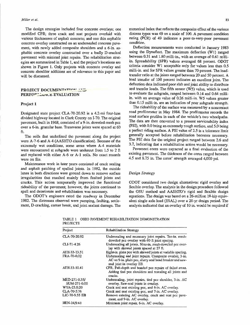
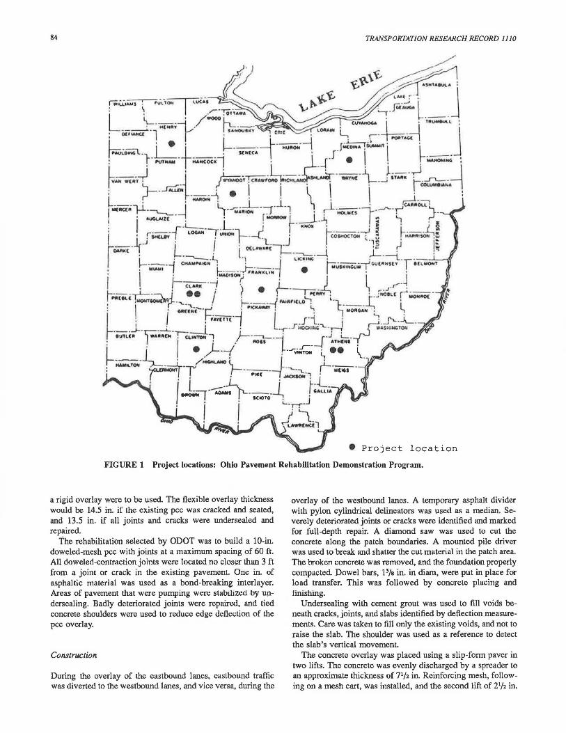
The design strategies included four concrete overlays; one modified CPR; three crack and seat projects overlaid with various thicknesses of asphalt concrete; and one thin asphaltic concrete overlay constructed on an undersealed concrete pavement, with newly added composite shoulders and a 6-in. asphaltic concrete overlay constructed over a badly D-cracked pavement with minimal joint repairs. The rehabilitation strategies are summarized in Table l, and the project's locations are shown in Figure 1. Only projects with concrete overlay and concrete shoulder additions are of relevance to this paper and will be discussed.
PROJECT DOCUMF.NTA'f'TA~~ _'_~:::;. PERFor~.:rt1"l\;.I!.: EVALUATION
Project 1
Designated state project CLA-70-20.92 is a 4.2-mi four-lane divided highway located in Clark County on I-70. The original pavement, built in 1968, consisted of a 9-in. doweled-mesh pee over a 6-in. granular base. Transverse joints were spaced at 60 ft.
The soils that underlined the pavement along the project were A-7-6 and A-4 (AASHTO classification). Because of the extremely wet conditions, some areas where A-4 materials were encountered at subgrade were undercut from 1.5 to 2 ft and replaced with either A-6 or A-1 soils. No exact records were on file.
Maintenance work in later years consisted of crack sealing and asphalt patching of spalled joints. In 1982, the outside lanes in both directions were ground down to remove surface irregularities that resulted mainly from faulted joints and cracks. This action temporarily improved the functional rideability of the pavement; however, the joints continued to spall and deteriorate and rehabilitation was necessary.
The ODOT's engineers rated the roadway in December 1982. The distresses observed were pumping, faulting, settlement, D-cracking, comer break, and joint sealant damage. The
83
numerical index that reflects the composite effect of the various distress types was 49 on a scale of 100. A pavement condition rating (PCR) of 49 indicates a poor-to-very-poor pavement condition.
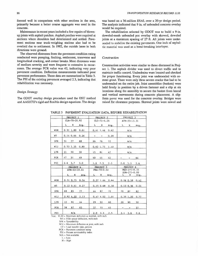
Deflection measurements were conducted in January 1983 using the Dynaflect. The maximum deflection (Wl) ranged between 0.31 and 1.80 milli-in., with an average of 0.61 milliin. Spreadability (SPR) values averaged 68 percent. ODOT criteria consider Wl acceptable only for values less than 0.5 milli-in. and for SPR values greater than 70 percent. The loadtransfer ratio at the joints ranged between 20 and 50 percent. A load transfer of 100 percent indicates an excellent joint. The deflection data indicated poor slab and joint ability to distribute and transfer loads. The fifth sensor (W5) value, which is used to evaluate the subgrade, ranged between 0.14 and 0.64 milliin. with an average value of 0.26 milli-in. W5 values greater than 0.15 milli-in. are an indication of poor subgrade strength.
The rideability of the surface was measured by a noncontact road profilometer in May 1984. The profilometer records the road surface profiles in each of the vehicle's two wheelpaths. The data are then converted to a present s~rviceability index (PSI), with 0.0 being an extremely rough surface, and 5.0 being a perfect riding surface. A PSI value of 2.5 is a tolerance limit generally accepted before rehabilitation becomes necessary. The PSI data for the original project ranged between 2.6 and 3.7, indicating that a rehabilitation action would be necessary.
Pavement cores were ex~acted as a final evaluation of the existing pavement. The thickness of the cores ranged between 4.5 and 8.75 in. The cores' strength averaged 4,000 psi.
Design Strategy
ODOT considered two design alternatives: rigid overlay and flexible overlay. The analysis in the design procedure followed the OSU method and AASHTO's rigid and flexible design equations. The design was based on a 26-million 18-kip equivalent single axle load (ESAL) over a 20-yr design period. The analysis indicated that an overlay of 10 in. would be required if
TABLE 1 OHIO PAVEMENT REHABILITATION DEMONSTRATION PROJECTS
Project
CLA-70-20.92
CLl-71-4.26
ATH-33-13.31 FRA-70-0.02
ATH-33-10.41
MED-271-0.35/ SUM-271-0.00
WYA-23.0.20 CLA-70-5.76 LIC-70-9.55 EB
HEN-24/9.61
Rehabilitation Strategy
Undersealing and necessary joint repairs. Ten-in. meshdoweled pee overlay with 60 ft joint spacing.
Undersealing all joints. Nine-in. mesh-doweied pee overlay with skewed joints spaced at 27 ft.
Eight-in. plain pee with skewed joints at variable spacing. Undersealing and joint repairs. Composite overlay, 3-in.
AC rm 9-in. plain pee, slurry seal bond breaker and sawseal joint in overlay EB.
CPR. Full-depth and bonded pee repairs of failed areas. Adding tied pee shoulders and resealing all joints and cracks.
Undersealing, joint repairs, tied pee shoulder, 3-in. AC overlay. Saw-seal joints in overlay.
Crack and seat existing pee, and 6-in. AC overlay. Crack and seat existing pee, and 7-in. AC overlay. Remove existing AC overlay, crack and seat pee pave-
ment, and 9-in. AC overlay. Minimum joint repair, 6-in. AC overlay.
84 TRANSPORTATION RESEARCH RECORD 1110
• Project location
FIGURE 1 Project locations: Ohio Pavement Rehabilitation Demonstration Program.
a rigid overlay were to be used. The flexible overlay thickness would be 14.5 in. if the existing pee was cracked and seated, and 13.5 in. if all joints and cracks were undersealed and repaired.
The rehabilitation selected by ODOT was to build a 10-in. doweled-mesh pee with joints at a maximum spacing of 60 ft. All doweled-contraction joints were located no closer than 3 ft from a joint or crack in the existing pavement. One in. of asphaltic material was used as a bond-breaking interlayer. Areas of pavement that were pumping were stabilized by undersealing. Badly deteriorated joints were repaired, and tied concrete shoulders were used to reduce edge deflection of the pee overlay.
Construction
During the overlay of the eastbound lanes, eastbound traffic was diverted to the westbound lanes, and vice versa, during the
overlay of the westbound lanes. A temporary asphalt divider with pylon cylindrical delineators was used as a median. Severely deteriorated joints or cracks were identified and marked for full-depth repair. A diamond saw was used to cut the concrete along the patch boundaries. A mounted pile driver was used to break and shatter the cut material in the patch area. The broken concrete was removed, and the foundation properly compacted. Dowel bars, 15/s in. in diam, were put in place for load transfer. This was followed by concrete placing and finishing.
Undersealing with cement grout was used to fill voids beneath cracks, joints, and slabs identified by deflection measurements. Care was taken to fill only the existing voids, and not to raise the slab. The shoulder was used as a reference to detect the slab's vertical movement.
The concrete overlay was placed using a slip-form paver in two lifts. The concrete was evenly discharged by a spreader to an approximate thickness of 71/2 in. Reinforcing mesh, following on a mesh cart, was installed, and the second lift of 21/2 in.
Miller el al.
was followed by the second placer-spreader. Final consolidation and distribution of the concrete was completed with rotary augers, and hand vibrators were used to consolidate the concrete around the dowels. Finishing, texturing, and spray-on curing compound followed. Construction joints were sawed and tied concrete shoulders were added. The construction activities were completed on October 15, 1984.
Pavement Evaluation
A field evaluation of the constructed pavement was conducted at periods of 6, 12, and 18 months after construction.
No distresses were noticed in the 6- or 12-month evaluation after the construction survey. However, in the April 1986 survey (at 18 months), hairline transverse cracking was noticed occasionally. The pavement joints were constructed at 60 ft, whereas the shoulder joints were constructed at 20 ft. The difference in slab length between the shoulder and the main
85
pavemenl resulted in Wlffiatchcd joints and may be responsible for these cracks. Shoulder slabs expand and contracl differently from the main pavement slabs. The tie bars, acting like a load transfer, created the cracks. It is anticipated that they will be controlled by the wire mesh reinforcement. A 45-degree crack, possibly due to a settlement problem, was also noted in a 50-ft section.
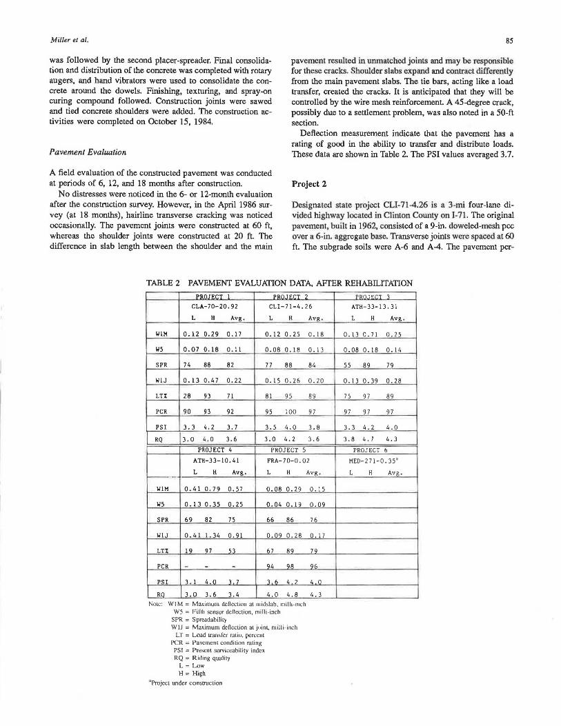
Deflection measurement indicate that the pavement has a rating of good in the ability to transfer and distribute loads. These data are shown in Table 2. The PSI values averaged 3.7.
Project 2
Designated state project CLI-71-4.26 is a 3-mi four-lane divided highway located in Clinton County on 1-71. The original pavement, built in 1962, consisted of a 9-in. doweled-mesh pee over a 6-in. aggregate base. Transverse joints were spaced at 60 ft. The subgrade soils were A-6 and A-4. The pavement per-
TABLE 2 PAVEMENT EVALUATION DATA, AFfER REHABILITATION
oon1F:r.T I DDnTF:r.T ?
CLA-70-20. 92 CLI-71-4. 26
L H Avg. L H Avg .
WlM 0.12 0.29 0 .17 0. 12 0.25 o. 18
W5 0.07 0.18 0.11 0.08 o. 18 o. 13
SPR 74 88 82 77 88 84
WIJ 0.13 0.47 0.22 0.15 0.26 0.20
LT% 28 93 71 81 95 89
PCR 90 93 92 95 100 97
PSI 3.3 4.2 3.7 3.5 4.0 3. 8
RQ 3.0 i. .o 3.6 3.0 4. 2 3.6
PROJECT 4 PROJECT 5
ATH-33-10.41 FRA-70-0.02
L H Avg. L H - ·-· WlM o. 41 0.79 0.57 0.08 0.29
W5 0. 13 o. 35 0.25 0.04 o. 19
SPR 69 82 75 66 86
WlJ 0.41 1. 34 0.91 0.09 0.28
LT% 19 97 53 67 89
PCR - - - 'l4 98
PSI 1. 1 4.0 1 7 1 n 4 2
RO 3.0 3.6 3.4 4.0 4.8 Note: WI M = Maximum dencction at midslab, milh-mch
W5 = Fifth sensor dencction. milli-inch SPR = Sprcadability WIJ = Maximum denection al j<1int. milli-inch
LT= Load transfer ratio, percent PCR = Pavement condition rating PSI = Prescnl serviceability index RQ = Riding quality
L =Low H =High
"Project WJder consttuction
Avg .
0.15
0.09
76
o. 17
79
96
4 0
4. 3
pon TF.C:T 1
ATH-33-13.31
L H Avg .
0.13 0.71 0.25
0.08 0. 18 o. 14
55 89 79
0. 13 0.39 0.28
75 97 89
97 97 97
3.3 4. 2 4.0
3.8 4.7 4.3
PROJECT 6
MED-271-0. 35•
L H Avg.
86
formed well in comparison with other sections in the area, primarily because a betrer coarse aggregate was used in the concrete.
Maintenance in recent years included a few repairs of blownup joints with asphalt patches. Asphalt patches were required at sections where shoulders had deteriorated and settled. Pavement sections near truck-weighing stations also had to be overlaid due to settlement. In 1982, the outside lanes in both directions were ground
The observed distresses from the pavement-condition rating conducted were pumping, faulting, setllement, transverse and longitudinal cracking, and comer breaks. Most distresses were of medium severity and were frequent to extensive in occurrence. The average PCR value was 42, indicating very poor pavement condition. Deflection measurements indicated poor pavement performance. These data are summarized in Table 3. The PSI of the existing pavement averaged 2.3, indicating that rehabilitation was necessary.
Design Strategy
The ODOT overlay design procedure used the OSU method and AASHTO's rigid and flexible design equations. The design
TRANSPORTATION RESEARCH RECORD 1110
was based on a 36-million ESAL over a 20-yr design period. The analysis indicated that 9 in. of unbonded concrete overlay would be required
The rehabilitation selected by ODOT was to build a 9-in. doweled-mesh unbonded pee overlay with skewed, doweled joints at a maximum spacing of 27 ft. All joints were undersealed to stabilize the existing pavements. One inch of asphaltic material was used as a bond-breaking interlayer.
Construction
Construction activities were similar lo those discussed in Project 1. The asphalt divider was used lo divert traffic and to maintain traffic control. Underdrains were located and checked for proper functioning. Every joint was undersealed with cement grout. There were only three severe cracks that had to be undersealed on the entire job. Joint assemblies (baskets) were held firmly in position by a driven fas tener and a clip at six locations along the assembly to secure the basket from lateral and vertical movements during concrete placement. A slipform paver was used for the concrete overlay. Bridges were raised for clearance purposes. Skewed joints were sawed and
TABLE 3 PAVEMENT EVALUATION DATA. BEFORE REHABILITATION
'DIHUF.r:T I 'Dl>f'\J"F'r:T ?
CLA-70-20.92 CLI-71-4.26
L H Avg. L H AV'il. .
WlM 0.31 1. 80 0.6l 0.41 I. 46 0.62
W5 0.14 0.64 0.26 - - 0.28
SPR 5l 77 68 66 76 72
WlJ 0.53 1. 35 0.89 0.62 I. 7 5 I. lO
LT% 2l 50 30 15 81 47
PCR 47 51 49 40 45 42
PSI 2.6 3.7 3.0 1. 6 2.5 2. 3 oon1Fr:T 4 PDn If.CT S
ATH-33-10.41 FRA-70-0.02
L H AV'il.. L H AV'il..
WlM 0.31 0.75 0.54 0.37 I. 44 0.64
W5 0.12 0.41 0 . 27 0.15 0.68 0.30
SPR 69 85 77 44 87 72
WlJ 0.92 4.20 2.11 0.47 4.02 I. 01
LT'.t 12 91 44 29 92 60
PCR 58 67 63 37 55 45
PSI NIA 2.0 3.3 2. 5 Note: WlM = Maximum deflection al midslab, milli-inch
W5 = Fifth sensor deflection, milli -inch SPR = Sprcaclability WlJ = Maximum deflection al joint, milli-inch
LT = Load transfer ratio, percent PCR = Pavement condition rating
PSI = Present serviceability index NIA = Nol available
L =Low H =High
PROJECT 3 ATH-33-l3.3l
L H AVR.
N/A
N/A
N/A
N/A
NIA
- - 64
2.0 3.3 2.6
PROJECT 6 MED-271-0.35 SUM-271-0.00 L H AV'il..
0.26 0.58 0. 42.
0.13 0.36 0.24
70 87 82
0.39 I. 20 o. 77
20 90 50
- - 57
2. 1 3.6 2.6
Miller el al.
were 1/2 in. wide (a bit wider than normal practice) and 21/4 in. deep. Wider joint sealer (1 1/4 in. minimum) was used. This is expected to provide a smoother ride and less joint deterioration because better contraction-expansion would occur. Rumble strips were placed in the concrete-tied shoulders at approximately 1,200-ft intervals.
Pavement Evaluation
A field evaluation was performed 6 months after construction; this included pavement-condition rating, deflection measurements, and roughness. No distresses were noticed at this time, but hairline cracks were noticed occasionally in the northbound lanes that had been constructed first. As in Project 1, the difference in slab length between the pavement and shoulder (27 and 13 ft, respectively) resulted in unmatched joints that could be responsible for these cracks. Deflection and roughness measurements were good and are shown in Table 3.
Project 3
Project ATH-33-13.31 is a 2.2-mi four-lane divided highway located in Athens County on US-33. The original pavement, built in 1969, consisted of a 7-in. continuously reinforced concrete pavement (CRCP) over a 4-in. cement stabilized base. The anticipated traffic on this section is 5.6-million ESAL over a 20-yr design period. The subgrade is predominately A-6 soil. Maintenance in later years consisted of crack sealing and asphalt patching of spalled joints.
The pavement-condition rating, as part of the initial pavement documentation, identified pavement distresses consisting of settlements, transverse cracking, pressure spalling, and deteriorated patches. All distresses were medium to high in severity. The average PCR value was 64, which indicated poor pavement condition. The PSI for this pavement averaged 2.~ another indication of the need for rehabilitation.
Design Strategy
ODOT engineering judgment was used to select an overlay type. The rehabilitation selected was to build an 8-in. plain, undoweled pee pavement. The pavement joints were to be skewed and at variable spacing of 13, 16, 14, 15, and 13 ft.
Construction
Construction was similar to that described earlier in Projects 1 and 2. However, no joint repairs or undersealing of the existing pavement were done. The asphalt divider was used to divert and maintain traffic control. An asphalt bond-breaker interlayer of 1 to 2 in. was specified for this job. Transition sections at the beginning and end of the job were cut and replaced with 6 in. of asphalt base concrete. The overlay had tied concrete shoulders with rumble strips located between transverse joints.
Pavement Evaluation
A pavement-condition rating conducted 6 months after construction revealed no sign of distresses. Deflection measure-
87
ments were taken and found to be satisfactory. PSI values ranged between 3.3 and 4.2, with an average value of 4.0. The low PSI values, indicated at some sections by the profilometer, could be due to rough surface finish. However, roughness was not felt by the rider.
A summary of these data is shown in Table 2.
Project 4
ATH-33-10.41isa2.8-mi four-lane divided highway in Athens County on US-33 adjacent to Project 3, and has similar subgrade and traffic conditions. The original pavement, built in 1958, consisted of 9 in. of reinforced concrete pavement over 3 to 7 in. of variable granular subbase. Joints were constructed at 60 ft. The pavement had stabilized aggregate shoulders, which had been primed and sealed by ODOT maintenance forces in later years.
Pavement distresses were of low severity and consisted of faulting, settlements, occasional transverse cracking, and corner breaks. Joint spalling and joint sealant damage were medium to high in severity and were noticed frequently. Most distresses were observed in the truck lane.
Deflection measurements (as shown in Table 2) indicated that the pavement was structurally adequate for the anticipated traffic volume (2.9-million ESAL). However, deflections at different joints were high and showed poor load transfer.
ODOT Rehabilitation Decision
Based on the initial pavement evaluation discussed above, ODOT decided to utilize CPR techniques, without grinding, to improve the structural and riding conditions of the pavement. This consisted of partial-depth repair of failed areas, full-depth and bounded pee patching of deteriorated joints, cleaning and resealing of all joints and cracks, and replacing the deteriorated asphalt shoulder with pee-tied shoulders on the outside and full-depth asphalt on the median side.
Construction
Areas where spalling and failure occurred were marked and sawed to a variable depth to remove all loose and unsound concrete. The surface was cleaned by air blasting. Bonding grout, consisting of equal parts by volume of pee and sand, was applied Then patching was done using two types of concrete, (Types I and II) as follows:
Type I: The mixture consists of 1 part high-early-strength portland cement 1 1/2 parts fine aggregate, and 1 1/2 parts coarse aggregate by volume. Sufficient air-entraining agent shall be added to maintain an air content of 8 ± 2 percent. The slump is the minimum practical for placing and in no case shall it exceed 2 percent. The materials are mixed at the site. Ready-mixed concrete is not permitted. The mix is placed in the area to be patched while the bonding grout is still wet. Slightly overfilled and struck off with a vibrating screed drawn slowly across the area. Hand finishing with a wood float may be required to produce a tight, uniform surface.
Type Il: Patching material is made using quick setting concrete mortar. The mortar is mixed and placed as per manufacturer's
88
reconunendations. Coarse aggregate may be added in accordance with the manufacturer's instructions when the depth of the patch exceeds 1 in.
Full-depth joints and cracks to be repaired were sawed by a diamond saw blade outside the boundaries of the distress. The deteriorated patch was broken in place and removed. Care was taken not to damage the adjacent slabs.
The subbase was shaped and compacted and holes were drilled for the dowel bars at both ends of the patch. Dowel bars were then epoxied into these holes. Concrete mix was placed and cured. It was specified that repair sections greater than 10 ft by 10 ft in dimension should have reinforcement placed in the patch.
The joints and cracks were cleaned and sandblasted. Backer rope was installed, then hot-applied rubberized asphalt sealant (ASTM D-3405) was installed in all joints and cracks.
The asphalt shoulders were removed and the subbase underneath was shaped and compacted. Horizontal holes were drilled ( 1/4 in. in diam) in the edge of the pavement for tie bars. The deformed tie bars (~/a in. in diam and 18 in. long) were grouted center-to-center at 60 in. Paving of concrete shoulders followed.
Pavement Evaluation
The spalls and failed areas were repaired with two different concrete materials, Type I and Type II, as previously described. Type II patches performed satisfactorily when opened to traffic. However, half of the Type I patches were found unbonded with the concrete. These patches were replaced by Type II materials.
Field evaluation 6 months after rehabilitation revealed that all patches were performing well. Joint sealants were inspected and found debonded with the side of the joints in many situations. This debonding may be due to inadequate cleaning of the joints before installation of the sealer, or it may be due to the quality of the sealer itself. Concrete shoulders were performing well. The tied shoulders are expected to improve the performance of the concrete pavement by reducing the edge and comer deflections.
Deflection measurements were taken 6 months after rehabilitation. Considering the before-and-after readings, deflection measurements of treated joints showed considerable improvement in maximum deflection and moderate improvement in load transfer ratio. Since no midslab treatment was done, the deflection measurements at those locations were the same. Although no initial PSI values were available, it was indicated by the riding quality that the roughness of the pavement was reduced (see Table 2).
Project 5
Project FRA-70-0.02 is a 3.4-mi six-lane divided highway located in Franklin County on 1-70. The original pavement was built in 1968 and consisted of 9 in. of doweled-mesh pee pavement over a 6-in. aggregate base. Transverse joints were spaced at 60 ft. The subgrade soils that underlined the pavement section were A-4 and A-6. No major rehabilitation was
TRANSPORTATION RESEARCH RECORD 1110
undertaken on this project except routine maintenance work such as crack sealing and patching.
A pavement-condition rating was conducted in 1985 before rehabilitation. Distress consisted of settlements, faulting, D-cracking, and high severity transverse cracking in the truck lane. The average PCR value was 45, indicating very poor pavement condition. Deflection measurements also indicated poor slab and joint conditions. Roughness measurements (PSI) averaged 2.5 and were as low as 2.0 in some sections.
Design Strategy
ODOT considered a composite design for this pavement. The analysis in the design procedure used the OSU method and Corps of Engineers' overlay design equations for rigid pavements. The design was based on 22.1-million ESAL over a 20-yr design period. The recommended design consisted of 9 in. of plain pee with joints at random spacing so that all contraction joints would be located no closer than 3 ft from a joint or crack in the existing pavement. Joint repairs and undersealing were used to stabilize the existing pavement. One-quarter in. of slurry seal was used as a bond-breaking interlayer. The concrete pavement was overlaid with 3 in. of asphaltic pavement. ODOT also specified a section to saw and seal joints in the asphalt overlay to be the exact matchup of the concrete joints underneath.
Construction
Construction procedures were similar to those discussed in previous projects. An asphalt divider was used to maintain traffic control. Undersealing with cemem grout was undertaken for joints and slabs based on the deflection measuremenls. The deteriorated concrete joints were removed using the lift-out method. Full-depth saw cuts were made outside the boundaries of the distress. The pieces were then mechanically lifted out_ ot the pavement by a crane. This method is becoming a common removal method because less damage is done to the adjacent slabs and the subbase.
One-quarter in. of slurry seal bond-breaker was applied before the concrete overlay. Skewed joints in the overlay were spaced at 13-, 15-, 17-, and 12-ft repeated spacing. Maximum spacing between joints was specified at 20 ft. A 3-in. asphalt overlay followed
Two sections (in the same direction) were specified for transverse joints across the finished surface of the asphalt concrete to be saw cut and sealed. The first section (1.2 mi) used a sealant that met the requirements of ASTM D-3405. The second section (1.3 mi) used a joint sealer as specified in
• ................ _ ....... -- m. . 1 • _, - - - - ·- _J 1 ,_ ~- ___ : ..l-AJ\o.':111.1 V Nl l /.), ine sawcuLS weu; ~ u1. ueep auu -,,. u1. w1uv.
Pavement Evaluation
A field survey and deflection measurements were conducted 6 months after construction. Reflection cracking was noticed in all Janes and at every third joint. Those sections with sawsealed joints performed well. Only five joints were observed with a nonmatching saw cut and reflection cracks. Those cracks
Miller el al ,
were within 3 to 12 in. of the sawed joints. All deflection measurements were satisfactory (see Table 2). The average PSI value of this pavement was 4.0.
Project 6
Project MED-271-0.35 on 1-271 is a 7.05-mi four-lane divided highway located in Medina/Summit Counties. The original pavement, built in 1966, consisted of 10-in. doweled-meshreinforced concrete pavement over 4 to 7 in. of variable aggregate subbase. The pavement had 6 in. of asphalt shoulders.
Pavement distresses consisted of medium severity, pumping, faulting, and joint sealant damage occurring frequently along the pavement section. Transverse faulted cracks were severe in some sections but moderate in others. The average PCR value was 57. Shoulders were completely deteriorated (upheaved) mainly because of water infiltration problems.
Deflection measurements (shown in Table 3) indicated that the pavement deflection at midslab was satisfactory; however, some joint deflections were high and needed to be stabilized. Roughness measurements were not available.
ODOT Rehabilitation Decision
ODOT decided to improve the structural and riding conditions of the pavement by using concrete pavement rehabilitation techniques without grinding. The deteriorated asphalt shoulders were replaced with tied pee shoulders, and 3 in. of asphalt concrete were overlaid across the main pavement and the shoulders. In addition, tie bars were grouted in pavement slots at faulted cracks (crack repairs) as an experimental feature.
Construction
Construction was still in progress when this paper was written. Construction procedures were similar to those of Project 4. Shoulders were milled off, the subbase was compacted, and holes were drilled at 60 in. Hook bolt and expansion anchors were used to tie the plain concrete shoulders with the main pavement.
Faulted crack repairs started after the undersealing was completed at the crack. Two parallel partial-depth saw cuts were made with a diamond saw blade. The wedge between the saw cuts was removed with a jackhammer. The slot was 51/4 in. deep and l1/2 in. wide. The slots were 18 in. apart, and eight slots per lane were cut. They were then sandblasted and air cleaned. Next, deformed Number 8 tie bars (18 in. long) were placed. The remainder of the slot was filled with the epoxyresin adhesive material.
Pavement Evaluation
As construction was still in progress, field evaluation consisted of a survey condition of the new shoulders and deflection measurements to determine the effectiveness of the crack repairs.
The shoulder conditions were good. Crack deflection mea-
89
surements before and after the crack repair showed a significant decrease in maximum deflection and an increase in load transfer across the crack. These data, deflection measurements in faulted cracks, Project 6, are shown as follows:
Before Repair After Repair
Low High Average Low High Average
Wl 0.33 1.12 0.83 0.29 0.53 0.39 LT% 7 91 41 53 91 79 Norn: LT% = load transfer ratio, percent. Wl = maximum deHection.
SITE VISITS
A site visitation program by an engineering panel from FHWA, ODOT, and RII was undertaken to gather opinions on the performance evaluation on all projects. In general the different rehabilitation techniques used were favorably reviewed Each panel member was asked to assign a riding quality number for each project on a scale of 0 (poor) to 5 (excellent). The average value assigned for each project is shown in the in-text table for Project 4.
INITIAL CONCLUSIONS
The following are initial conclusions pending the completion of the performance-monitoring phase of the cited project:
1. Selection criteria of the rehabilitation strategies are based upon site-specific information including PCR, deflection measurements, PSI, and traffic. Currently, ODOT is developing a systematic reference based for such selection accounting for the above variables.
2. Because tied shoulders promote better edge-joint performance, the intermediate joints in the unreinforced shoulders result in transverse cracking beginning at these joints.
3. To guard against sealant debonding, observed in Project 4, adequate cleaning and sandblasting of both faces of the joint before the installation of the sealer are necessary. A higher quality material may be required to improve the adhesion of the sealant.
4. The Dynafiect need-to-repair criteria, which were established by ODOT, are judged to be satisfactory in this study. They were based on limited data from deflection measurements. However, a large data base may be required to fine-tune these criteria.
5. Long-term performance of these pavements will enable ODOT to determine the effectiveness of the rehabilitation technique. Cost data will be gathered along with the performance of each individual strategy to develop guidelines for future rehabilitation designs.
ACKNOWLEDGMENTS
This study was sponsored by the Federal Highway Administration and the Ohio Department of Transportation. The authors wish to thank the Bureaus of Research and Development, Location and Design, Technical Services, and Construction and
90
Maintenance at ODOT for their cooperation in providing the necessary information to complete this study.
Special thanks are also due to Donna Roberts for typing this manuscript and to Jack Holbrook for editing it.
REFERENCES
1. M. I. Darter, E. J. Barenberg, W. A. Yrjanson, G. R. Ashley, and P. A. Okamoto. Evaluation of Joint Repair Methods for PCC Pavements. NCHRP Project 1-21, University of Illinois, Urbana, 1981.
2. S. W. Dudley. Evaluation of Concrete Pavement Restoration Techniques. Ohio Department of Transportation, Columbus, Nov. 1983.
3. Asphalt Overlays and Pavement Rehabilitation. Asphalt Institute MS-17, College Park, Md., 1983.
4. Thickness Design Procedure for Bituminous Resurfacing of Portland Cement Concrete Pavements. Illinois Department of Transportation, Division of Highways, R&D Report 20, Springfield, 1971.
5. AASHTO Interim Guide for Design of Pavement Structure. American Association of State Highway and Transportation Officials, Washington, D.C., revised 1982.
6. K. Majidzadeh and G. J. Ilves. Evaluation of Rigid Pavement G 'iy Design Procedure, Development of the OAR P~ocedure.
TRANSPORTATION RESEARCH RECORD 1110
FHWA-RD-83/090; Final Report DTFHll-9489, Research International, Inc., 1983.
7. Evaluation of Asphalt Overlays. Utah Department of Transporta lion, Salt Lake City, 1970.
8. Asphalt Concrete Overlays of Rigid and Flexible Pavements. FHWA Report No. FHWA-LA-109, Sept 1977.
9. E. S. Lindon and J. J. Brown. A System for Life-Cycle Design of Pavements. Proc., First International Conference on Concrete Pavement Design, Purdue University, West Lafayette, Ind., 1977.
10. A Design Procedure for Continuously Reinforced Concrete Overlays. Continuously Reinforced Pavement Group, Concrete Reinforcing Steel Institute, Schaumburg, lli., 1973.
11. G. K. Ray. Design of Concrete Overlays for Pavements. ACI 324. IR-67 Journal of the American Concrete Institute, Aug. 1967.
12. M. I. Darter and E. J. Barenberg. Bonded Concrete Overlays Construction and Performance. U.S. Army Engineers Waterways Experiment Station, Vicksburg, Miss., 1979.
13. 0. Schnitter et al. A Rigid Pavement Overlay Design Procedure for Texas. Austin Research Report No. 177-13, Austin Research Engineers, Austin, May 1978.
14. K. Majidzadeh. The Study of Pavement Overlay Design. Final Report, Project EES 457, Ohio State University Engineering Experiment Station, Columbus, 1977.
Publication of this paper sponsored by Committee on Pavement Rehabilitation and Committee on Rigid Pavement Construction and Rehabilitation.
Field Evaluation of Concrete Pavement Consolidation
SHIRAZ D. TAYABJI AND DAVE WHITING
For long-term durability of concrete pavements, it is required that the concrete be adequately consolidated. Inadequate consolidation of concrete can result in weak concrete that may lead to premature failure or loss of serviceability of the pavement. Presented in this paper is the result of a comprehensive study on concrete pavement consolidation conducted by the Construction Technology Laboratories, Inc., and sponsored by the Federal Highway Administration. The scope of the work consisted of laboratory testing, evaluation of nuclear gauges, develonment of model accentance nlans for concrete consolidation, and field Implementation of the acceptance plans. In laboratory tests, consolldation was found to have a strong Influence on compressive strength, bond of concrete to reinforcing steel, and permeability of concrete. There was a lesser effect of consolidation on resistance to freezing and thawing. A loss of 30 percent was sustained in compressive strength for every S percent decrease in consolidation. A variety of nuclear
Construction Technology Laboratories, Inc., 5420 Old Orchard Road, Skokie, Ill. 60077.
density gauges was evaluated for use In monitoring consolidation of concrete. Information was obtained from literature sources and state highway agencies. Typical precision on field concrete ranges from 1 to 2 lb/ft3 (16 to 32 kg/m3) for most gauge types. A combination of techniques such as the consolidation monitoring device and commercial direct transmission gauges shows promise as means of monitoring consolidation during the paving process. A model acceptance sampling plan for concrete consolidation is proposed. The plan is of the insoection-bv-varlables tvne and reauires a samnle size of eight per lot: The plan provides for buyer's and seller's risks of S percent. Field trial of a model acceptance plan was carried out along a section of 1-86 in Idaho. The field study indicates that it is practical and cost effective to monitor concrete consolldation in the field.
Portland cement concrete (PCC) is a versatile, strong, and durable material for construction of highway pavements. However, the combination of traffic loading, wear, temperature stresses, freezing, and applications of deicing agents results in a