Embed Size (px)
Citation preview
http://www.iaeme.com/IJEET/index.asp 24 [email protected]
International Journal of Electrical Engineering & Technology (IJEET)
Volume 9, Issue 2, March-April 2018, pp. 24–36, Article ID: IJEET_09_02_004
Available online at http://www.iaeme.com/ijeet/issues.asp?JType=IJEET&VType=9&IType=2
ISSN Print: 0976-6545 and ISSN Online: 0976-6553
Journal Impact Factor (2016): 8.1891 (Calculated by GISI) www.jifactor.com
© IAEME Publication
COMPARISON OF DIFFERENT CONTROL
STRATEGIES FOR BLDC MOTOR DRIVE
SK.Sharmila, K.Esther Rani, A.Anil kumar and T.Naveen
Student, Department of Electrical & Electronics Engineering
Kallam Haranadhareddy Institute of Technology, Guntur, Andhra Pradesh, India
Prabhakara Sharma Pidatala
Associate Professor, Department of Electrical & Electronics Engineering
Kallam Haranadhareddy Institute of Technology, Guntur, Andhra Pradesh, India
ABSTRACT
Brushless DC (BLDC) motor drive is frequently gaining popularity due to their
high efficiency, good dynamic response and low maintenance. Therefore, it is
necessary to have a low cost, but effective BLDC motor speed/torque regulator. This
paper presents a comparison of different control strategies for Brushless DC (BLDC)
motor which the controllers has been designed by using two types of control strategies
first one addresses the PID (Proportional Integral Derivative) controller based on
pole placement technique and the second one addresses the IMC (Internal Model
Control) controller by closed loop control strategy. The simulation results are carried
out by using MATLAB/SIMULINK successfully for closed loop operation of the three
phases BLDC motor. The performance characteristics i.e. speed and load torque of a
BLDC Motor compared for both with and without PID and IMC controllers. The
results presented validate control strategies in improving the motor performance.
Keywords: Brushless DC motor (BLDCM), Hall sensors, PID controller, IMC
controller
Cite this Article: SK.Sharmila, K.Esther Rani, A.Anil kumar, T.Naveen and
Prabhakara Sharma Pidatala, Comparison of Different Control Strategies for BLDC
Motor Drive, International Journal of Electrical Engineering & Technology, 9(2),
2017, pp. 24–36.
http://www.iaeme.com/ijeet/issues.asp?JType=IJEET&VType=9&IType=2
1. INTRODUCTION
Since 1980’s new archetype concept of permanent magnet brushless dc motors has been built
to eliminate sparking, high maintenance, high cost. BLDC motor rapidly growing to satisfy
the demand of household appliances in the market. Common household appliances which use
electric motors include air conditioners, refrigerators, vacuum cleaners, washers and dryers.
However, consumers now demand better performance, reduced acoustic noise [1] and higher
efficient motor for their appliances. Hence, BLDC have been introduced in order to fulfil
Comparison of Different Control Strategies for BLDC Motor Drive
http://www.iaeme.com/IJEET/index.asp 25 [email protected]
these requirements. In the event of replacing the function of alternators and brushes, the
BLDC motor requires a six pulse inverter and a hall sensor which detects rotor position for
appropriate alternation of current. BLDC motor generally adopts three hall sensors for
deciding the commutation sequence [2]. Some of the benefits are more desirable in speed
versus torque characteristics, high dynamic response, high efficiency, long operating life,
noiseless operation; higher speed ranges [2]. The BLDC are typically permanent synchronous
motor, they are well driven by dc voltage.
However, there are drawbacks in a BLDC motor because of variable speed, and therefore
various controllers are used to overcome these problems. In this paper, we propose to observe
and compare the performance of BLDC motor by Speed Torque characteristics of the BLDC
motor by using PID controller [5] and IMC controller [7]. PID controller basically used to
obtain stability of a system to reduce steady state error and to get better performance of a
system. IMC controller [7] which states that control can be achieved only if the control
system contain either implicitly or explicit then some representation of the process to be
controlled.
2. CONSTRUCTION AND OPERATING PRINCIPLE
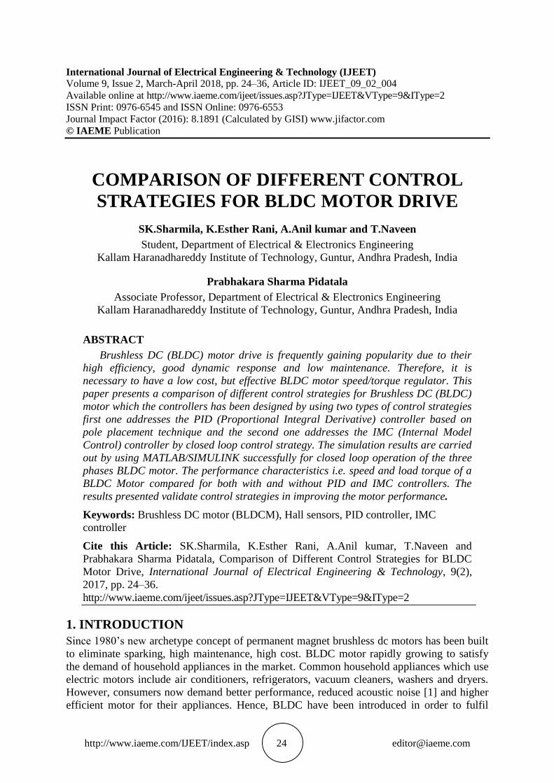
It consists of a dc supply by a rectifier arrangement, a dc link capacitor for energy storage, a
Voltage Source Inverter (VSI) consisting of transistor switches, and finally, the three-phase
output of the inverter is supplied to the motor for position sensing purposes, (Hall position
sensor) which is used along with some sort of microcontroller/microprocessor. Although
snubbers are not shown, it is a practice to include snubbers to protect the transistor switches
from voltage spikes generated by switching (fluctuations). Basically, BLDC motor is built
with a permanent magnet rotor and wire wound stator poles.
Figure 1 Represents a BLDC motor along with rectifier and six pulse inverter.
The electromagnetic torque is given by
= phase to neutral back emf of phase A (in volts)
= phase to neutral back emf of phase B (in volts)
= phase to neutral back emf of phase C (in volts)
=current in phase A (in amps)
=current in phase B (in amps)
=current in phase C (in amps)
=angular velocity of the rotor shaft (in radians/sec)
SK.Sharmila, K.Esther Rani, A.Anil kumar, T.Naveen and Prabhakara Sharma Pidatala
http://www.iaeme.com/IJEET/index.asp 26 [email protected]
( ) ( )
( )BLDC motors are a kind of permanent magnet synchronous
motor. This indicates the magnetic field produced by the stator and the magnetic field
produced by the rotor twirls or rotates at the same frequency. BLDC motor do not experience
the ―slip‖ which is normally observed in induction motors. The stator magnetic circuit is
usually made from magnetic steel sheets. Stator phase windings are inserted in the slots
(distributed winding). Magnetization of the permanent magnets and their displacement on the
rotor are chosen in such a way that the back-EMF (the voltage induced into the stator winding
due to rotor movement) shape is trapezoidal. This allows a rectangular-shaped 3-phase
voltage system to create a rotational field with low torque ripples.
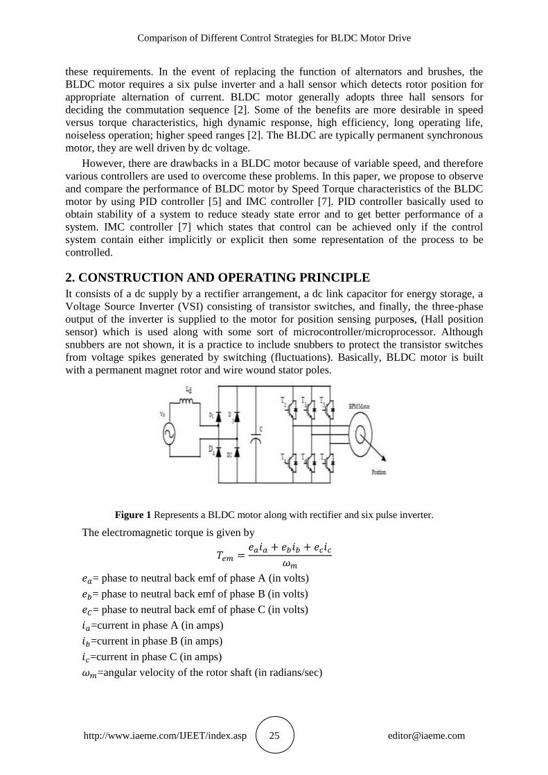
3. EQUIVALENT CIRCUIT DIAGRAM FOR A BLDC MOTOR
A typical dc motor equivalent circuit is illustrated as shown in the circuit shown below. The
basic components of a dc motor represented as armature resistance R and the armature
inductance L in addition, there is the back emf, e. From the figure, the following equations are
used to describe the relationship of operation.
Using the Kirchhoff’s Voltage Law equation is obtained as:
Figure 2 Typical dc motor equivalent electrical Circuit.
( ) ( )
( ) ( )
Similarly, considering the mechanical properties of the dc motor, from the Newton’s
second law of motion, the mechanical properties relative to the torque of the system
arrangement is
4. POSITION SENSORS OF A BLDC MOTOR (HALL SENSORS)
BLDC motor has three hall sensors which is placed in stator by 120 degrees each and
performs the function of six step commutation. when the rotor passes a sensor, it produces
either a high or a low signal to indicate which rotor pole (N or S) has passed this switching of
the three hall effect sensors (from high to low or low to high) provides rotor position
information every 60 degrees .The purpose of commutation is to energize the stator windings
in a particular sequence, following one winding positive, one negative, and third winding as
powered off. Torque production is possible by having attraction and repulsion between the
stator field and the permanent magnets of a rotor. The maximum torque is possible only when
the two fields of stator and rotor gets oriented at 90 degrees to each other and torque gets
reduced other than 90 degrees. Therefore, in order to keep the motor turning the stator
magnetic field should change position as the rotor field.
Comparison of Different Control Strategies for BLDC Motor Drive
http://www.iaeme.com/IJEET/index.asp 27 [email protected]
5. DESIGN OF PID AND IMC CONTROLLERS
A. PID CONTROLLER
The Proportional-Integral-Derivative (PID) controller is about the most common and useful
tool in control systems engineering. In most of the cases, feedback loops are controlled using
the PID algorithm. The main reason why feedback is very important in systems is to be able
to attain a set-point irrespective of disturbances or any variation in characteristics of any form.
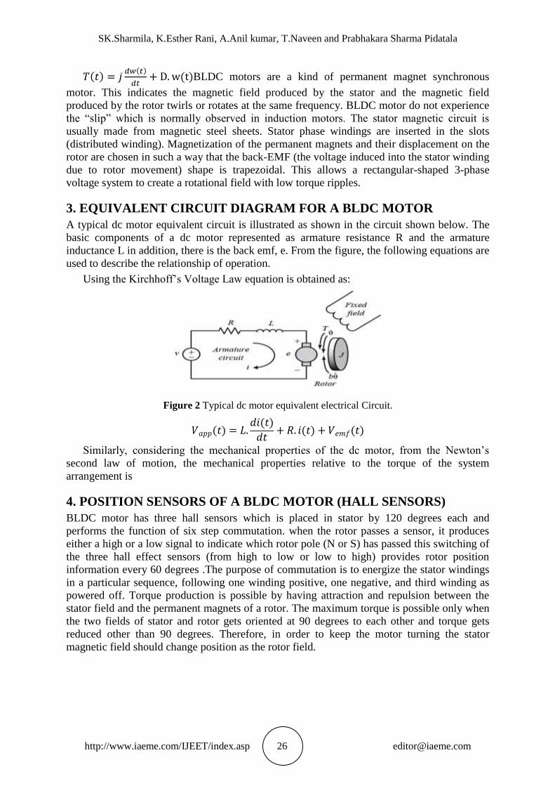
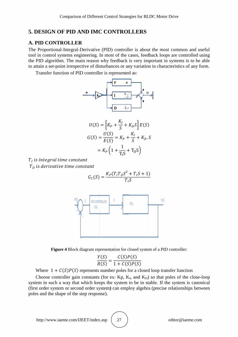
Transfer function of PID controller is represented as:
( ) [ ] ( )
( ) ( )
( )
(
)
( ) (
)
Figure 4 Block diagram representation for closed system of a PID controller:
( )
( )
( ) ( )
( ) ( )
Where ( ) ( ) represents number poles for a closed loop transfer function
Choose controller gain constants (for ex: Kp, KI, and KD) so that poles of the close-loop
system in such a way that which keeps the system to be in stable. If the system is canonical
(first order system or second order system) can employ algebra (precise relationships between
poles and the shape of the step response).
SK.Sharmila, K.Esther Rani, A.Anil kumar, T.Naveen and Prabhakara Sharma Pidatala
http://www.iaeme.com/IJEET/index.asp 28 [email protected]
If the system is non-canonical (higher order system) the relationships is not exist. One
idea is to place one or two dominant poles to meet our requirements and place the rest of
poles to be significantly faster, so that we can able to sense and omit the effect of the
dynamics for the other transient response.
Proportional gain constant
Integral gain constant
If a system does not have desired response (peak time too large, time response large, much
oscillation, large overshoot) then it can be modified with control.
(Delay Time): It is the time needed for the response to reach half of its final value the
very first time.
tr (Rise Time): It is the time needed for the response to rise from 10% to 90%.
(Peak Time): It is the time needed for the response to reach the first peak of the
overshoot.
(Maximum percent Overshoot): It is the maximum peak value of the response curve.
ts (Settling Time): It is the time required for the response curve to reach and stay within
2% of the final value. Consider the characteristics parameters – proportional (P), integral (I),
and derivative (D) controls, the system, S is to be controlled using the controller, C; where
controller, C efficiency depends on the P, I and D parameters
A. INTERNAL MODEL CONTROLLER
Basically Internal Model Control (IMC) principle states that ―Control can be achieved if and
only if the control system contains either implicitly or explicitly, some representation of the
process to be controlled‖.
The Internal Model Control (IMC) based approach for PID controller design can be used to
control applications in industries. Hence, controller design that maintains disturbance
rejection rather than set point tracking. The parameters of IMC controller depend on the IMC
filter time constant. Increase in the filter time constant always reduces the overshoot to an
acceptable limit, but however reduces the disturbance rejection, desired noise suppression
capability. This study also proposes the procedure method for selection of filter time constant.
6. IMC STRATEGY
The Internal Model Control (IMC) based approach for PID controller design can be used to
meet the requirements in industries hence by using IMC-PID tuning method a clear trade-off
between closed loop performance and robustness to model inaccuracies is achieved with a
single tuning parameter. The actual usefulness of the IMC lies in the fact that much concern
can be put on controller design rather than control system. Stability provided that the process
model is a perfect representation of a stable process.
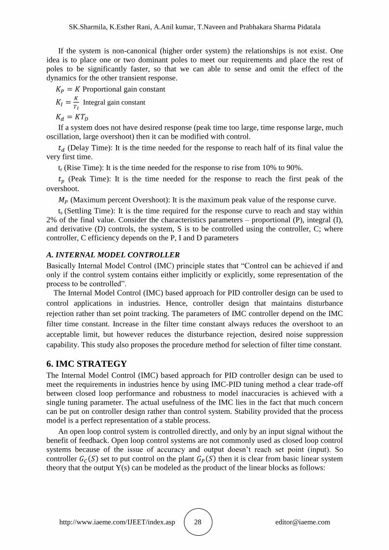
An open loop control system is controlled directly, and only by an input signal without the
benefit of feedback. Open loop control systems are not commonly used as closed loop control
systems because of the issue of accuracy and output doesn’t reach set point (input). So
controller ( ) set to put control on the plant ( ) then it is clear from basic linear system
theory that the output Y(s) can be modeled as the product of the linear blocks as follows:
Comparison of Different Control Strategies for BLDC Motor Drive
http://www.iaeme.com/IJEET/index.asp 29 [email protected]
Figure 5 Block diagram representation for open loop system of an IMC controller
( ) ( ) ( ) ( )
Then set point tracking can be achieved by designing a controller such that:
( ) ( )
This control performance characteristic is achieved without feedback results inaccuracy.
These features are:
Hence, set point tracking can be achieved by designing a feedback controller such that:
( ) [ ( ) ( )] ( ) ( )
⌈ ( ) ̃ ( )⌉ ( )Feedback control can be theoretically achieved if
complete characteristic features of the process are known feedback control is only necessary
when the process is inaccurate or incomplete. In real life applications, however, process
models have potential of contradiction with the parent process; hence feedback control
schemes are designed to resist or prevent the effects of this mismatching.
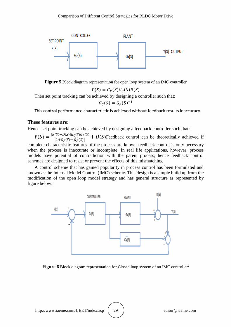
A control scheme that has gained popularity in process control has been formulated and
known as the Internal Model Control (IMC) scheme. This design is a simple build up from the
modification of the open loop model strategy and has general structure as represented by
figure below:
Figure 6 Block diagram representation for Closed loop system of an IMC controller:
SK.Sharmila, K.Esther Rani, A.Anil kumar, T.Naveen and Prabhakara Sharma Pidatala
http://www.iaeme.com/IJEET/index.asp 30 [email protected]
Where it have parameters like:
Controller ( )
Process ( )
Internal model ̃( )
Disturbance ( )
For the nominal case ( ) ̃( )
Feedback is only affected by disturbance ( ) such that the system is effectively open
loop and hence no stability problems can arise. This control structure also depicts that if the
process ( ) is stable, which is true for most industrial processes, the closed loop will be
stable for any stable controller ( ) Thus, the controller ( ) can simply be designed as a
feed-forward controller in the IMC scheme.
IMC scheme is therefore given by
This brings about two important advantages of applying IMC control scheme. The closed
loop stability can obtain by choosing a stable IMC controller. The closed loop performances
are related directly to the controller parameter, which makes on-line tuning of the IMC
controller very convenient.
Some important properties of IMC scheme
It provides time delay compensation.
Reference signal tracking and disturbance rejection responses can be shaped by a single
filter.
The controller gives offset free responses at the steady state.
7. SIMULATION & ANALYSIS
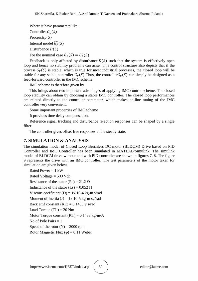
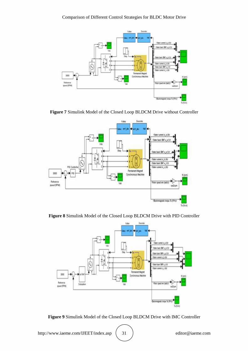
The simulation model of Closed Loop Brushless DC motor (BLDCM) Drive based on PID
Controller and IMC Controller has been simulated in MATLAB/Simulink. The simulink
model of BLDCM drive without and with PID controller are shown in figures 7, 8. The figure
9 represents the drive with an IMC controller. The test parameters of the motor taken for
simulation are given below.
Rated Power = 1 kW
Rated Voltage = 500 Vdc
Resistance of the stator (Rs) = 21.2 Ω
Inductance of the stator (Ls) = 0.052 H
Viscous coefficient (D) = 1x 10⁻⁴ kg-m s/rad
Moment of Inertia (J) = 1x 10⁻⁵ kg-m s2/rad
Back emf constant (KE) = 0.1433 v s/rad
Load Torque (TL) = 20 Nm
Motor Torque constant (KT) = 0.1433 kg-m/A
No of Pole Pairs = 1
Speed of the rotor (N) = 3000 rpm
Rotor Magnetic Flux (φ) = 0.11 Weber
Comparison of Different Control Strategies for BLDC Motor Drive
http://www.iaeme.com/IJEET/index.asp 31 [email protected]
Figure 7 Simulink Model of the Closed Loop BLDCM Drive without Controller
Figure 8 Simulink Model of the Closed Loop BLDCM Drive with PID Controller
Figure 9 Simulink Model of the Closed Loop BLDCM Drive with IMC Controller
SK.Sharmila, K.Esther Rani, A.Anil kumar, T.Naveen and Prabhakara Sharma Pidatala
http://www.iaeme.com/IJEET/index.asp 32 [email protected]
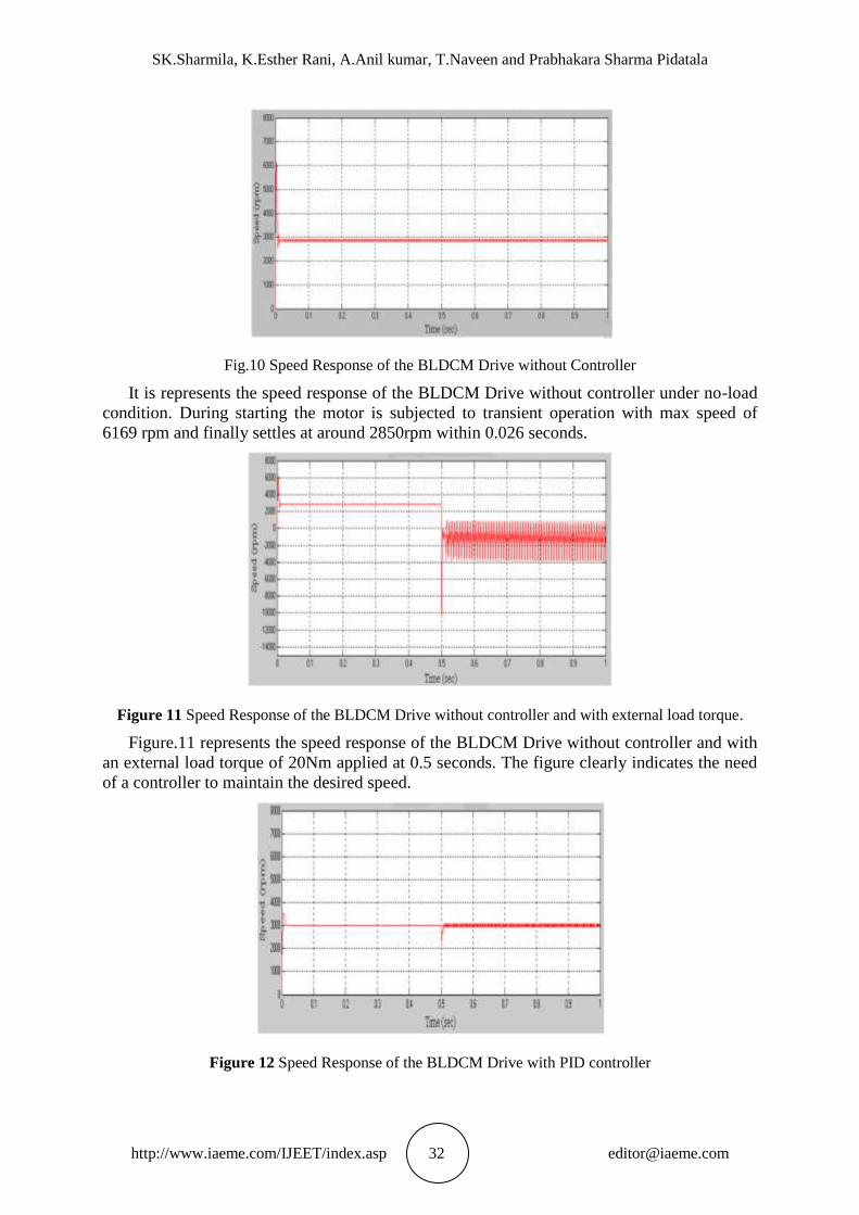
Fig.10 Speed Response of the BLDCM Drive without Controller
It is represents the speed response of the BLDCM Drive without controller under no-load
condition. During starting the motor is subjected to transient operation with max speed of
6169 rpm and finally settles at around 2850rpm within 0.026 seconds.
Figure 11 Speed Response of the BLDCM Drive without controller and with external load torque.
Figure.11 represents the speed response of the BLDCM Drive without controller and with
an external load torque of 20Nm applied at 0.5 seconds. The figure clearly indicates the need
of a controller to maintain the desired speed.
Figure 12 Speed Response of the BLDCM Drive with PID controller
Comparison of Different Control Strategies for BLDC Motor Drive
http://www.iaeme.com/IJEET/index.asp 33 [email protected]
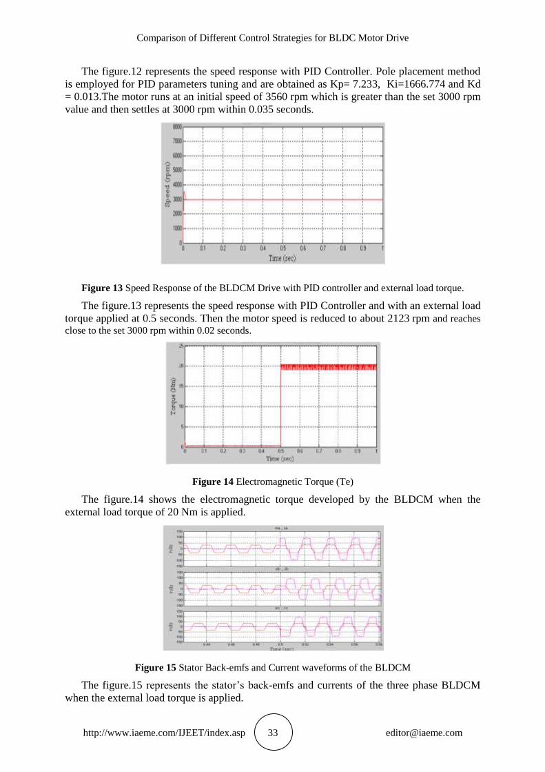
The figure.12 represents the speed response with PID Controller. Pole placement method
is employed for PID parameters tuning and are obtained as Kp= 7.233, Ki=1666.774 and Kd
= 0.013.The motor runs at an initial speed of 3560 rpm which is greater than the set 3000 rpm
value and then settles at 3000 rpm within 0.035 seconds.
Figure 13 Speed Response of the BLDCM Drive with PID controller and external load torque.
The figure.13 represents the speed response with PID Controller and with an external load
torque applied at 0.5 seconds. Then the motor speed is reduced to about 2123 rpm and reaches
close to the set 3000 rpm within 0.02 seconds.
Figure 14 Electromagnetic Torque (Te)
The figure.14 shows the electromagnetic torque developed by the BLDCM when the
external load torque of 20 Nm is applied.
Figure 15 Stator Back-emfs and Current waveforms of the BLDCM
The figure.15 represents the stator’s back-emfs and currents of the three phase BLDCM
when the external load torque is applied.
SK.Sharmila, K.Esther Rani, A.Anil kumar, T.Naveen and Prabhakara Sharma Pidatala
http://www.iaeme.com/IJEET/index.asp 34 [email protected]
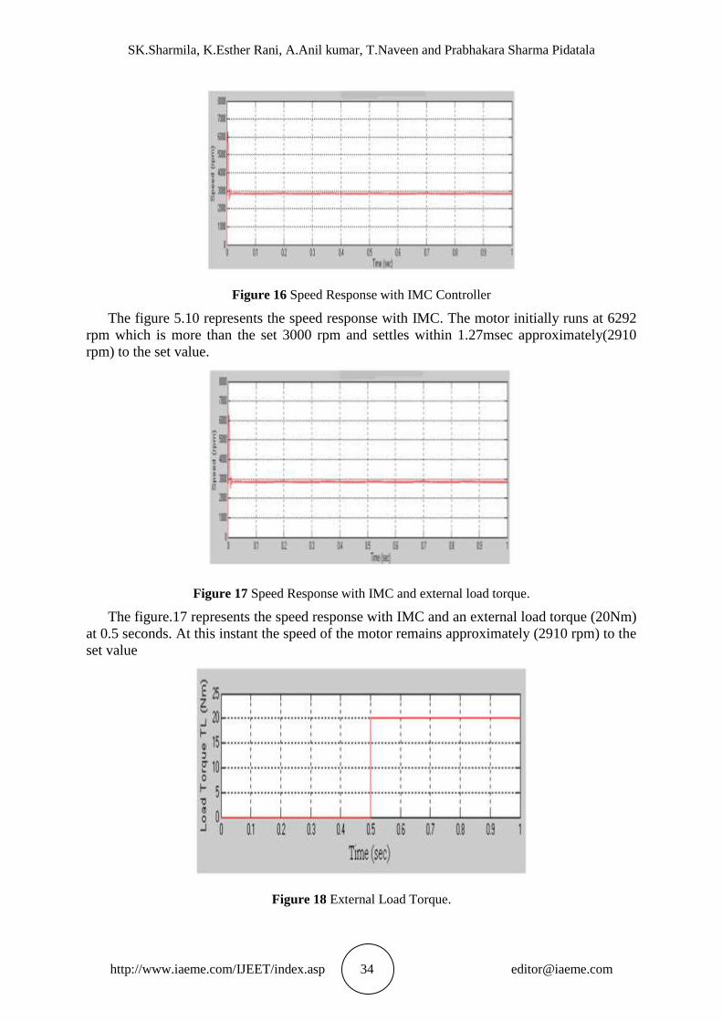
Figure 16 Speed Response with IMC Controller
The figure 5.10 represents the speed response with IMC. The motor initially runs at 6292
rpm which is more than the set 3000 rpm and settles within 1.27msec approximately(2910
rpm) to the set value.
Figure 17 Speed Response with IMC and external load torque.
The figure.17 represents the speed response with IMC and an external load torque (20Nm)
at 0.5 seconds. At this instant the speed of the motor remains approximately (2910 rpm) to the
set value
Figure 18 External Load Torque.
Comparison of Different Control Strategies for BLDC Motor Drive
http://www.iaeme.com/IJEET/index.asp 35 [email protected]
8. CONCLUSION
Comparison of performance characteristics of a BLDC motor drive with two different control
strategies by using Matlab/Simulink software.
By the design of PID controller by the method of pole placement technique the gain
constant parameters are obtained as Kp=7.233, Ki=1666.774, Kd=0.013. The major advantage
obtained is maximum overshoot of the speed response of BLDC motor drive is approximately
equal to zero which results in system to be in stable and has observed stator back emf and
current waveforms of a BLDC motor drive. The stability of a system mainly depends upon
characteristic equation of a closed loop control system of a PID controller by pole placement
technique.
The IMC Controller which is designed based on a PID controller the parameters results as
rise time tr=o.oo127 sec, peak time tp=0.0035 sec, settling time ts=0.0197 sec. Even though
having maximum overshoot of a speed response to be high, the transient parameters gives fast
response as compared to PID controller. Elimination of inaccuracy of a system and time delay
compensation with very greater accuracy is done by an IMC based PID controller.
REFERENCES
[1] C.Gencer and M.Gedicpinar, Modeling and Simulation of BLDCM Using
MATLAB/SIMULINK, Journal of Applied Sciences 6(3):688-691,2006.
[2] Atef Saleh Othman Al-Mashakbeh Proportional Integral and Derivative Control of
Brushless DC Motor European Journal of Scientific esearchVol.35 No.2, pp.198-
203,2009.
[3] Microchip Technology, Brushless DC (BLDC) motor fundamentals, application
note,AN885, 2003.
[4] Gwo-Ruey yu and Rey-Chue Hwang Optimal PID Speed Control of Brushless DC Motors
Using LQR approach IEEE International Conference on systems, Man and Cybernetics,
2004, pp.473-478.
[5] K.Ang, G.Chong, and Y. Li, PID control system analysis, design, and technology, IEEE
Trans. Control System Technology, vol. 13, pp. 559- 576,July 2005.
[6] Bergh, L.G. MAC Gregory. J.F. constrained minimum variance- Internal model structure
and robustness properties. IND. Eng chem. Res. 1986, 26, 1558.
[7] Chein L-L Fruehauf, P.S consider IMC tuning to improve controller performance. Chem.
Eng. Prog 1990, 86, 33.
[8] Rivera, D.E.Skogestad, S.Morari M.IMC 4: PID controller design. Ind.Eng chem..Process
des.Dev 1986, 25,252.
[9] Allan R. Hambley, Electrical Engineering Principles and Application, Prentice Hall, New
Jersey 1997.
[10] N. Mohan, T.M. Undeland, and W.P. Robbins, Power Electronics Converters,
Applications, and Design, New York: John Wiley & Sons, 1995.
[11] Anand Vaz , S.S.Dhami and Sandesh Trivedi, Bond Graph Modeling and Simulation of
Three phase PM BLDC Motor, 14th National Conference on Machines and Mechanisms
(NaCoMM09),NIT, Durgapur, India, December 17-18, 2009.
[12] M.Aboelhassan, A Proportional Integral Derivative (PID) Feedback Control without a
Subsidiary Speed Loop. Acta Polytechnica Vol.48 No.3,PP.7-11,2008.
[13] K.Ogata, Modern Control Engineering, New Delhi, India: Prentice-Hall of India Pvt. Ltd.,
1991.
[14] A. Kaya and T. J. Scheib, Tuning of PID controls of different structures, Control Eng.,
vol. 35, no. 7, pp. 62–65, Jul. 1988.
SK.Sharmila, K.Esther Rani, A.Anil kumar, T.Naveen and Prabhakara Sharma Pidatala
http://www.iaeme.com/IJEET/index.asp 36 [email protected]
[15] Y. Li, W. Feng, K. C. Tan, X. K. Zhu, X. Guan, and K. H. Ang, PIDeasy and automated
generation of optimal PID controllers, in Proc. 3rd AsiaPacific Conf. Control and
Measurement, Dunhuang, P.R. China, 1998, pp. 29–33.
[16] A. O’Dwyer, Handbook of PI and PID Controller Tuning Rules. London, U.K.: Imperial
College Press, 2003.
[17] Specialized Control. (2002, Jun.) PID Control Tuning—Analytical PID Tuning Methods
for Feedback Control Systems. [Online] http://www.specializedcontrol.com.
AUTHOR’S DETAIL
Sk.Sharmila student of B.Tech Final year in Electrical and Electronics
Engineering department, She is one of the department topper and is
placed in academic outstanding excellence. She has interest areas are
Electrical Machines, Power Systems, Control Systems.
Esther Rani. Karri student of B.Tech Final year Electrical and
Electronics Engineering department, During his graduation program
she had involved various technical presentations on Electrical
Networks, Electrical Machines and Power Electronics.
Anil Kumar.A student of B.Tech Final year Electrical and Electronics
Engineering department. His area of interest includes Control
Systems, Electrical Machines and Power Electronics.
Naveen Tadigiri student of B.Tech Final year Electrical and
Electronics Engineering department, His area of interest includes
Power Electronics, Electrical Measurements and Control Systems.
Prabhakara Sharma.Pidatala obtained his B.Tech. in EEE from
Koneru Lakshmaiah College of Engineering, Green fields, AP, India.
He completed his Master of Technology in High Voltage Engineering
from University College of Engineering, JNTU-Kakinada, AP, India
and pursing Ph.D in Andhra University. He is currently working as
Associative Professor in department of Electrical & Electronics
Engineering in Kallam Haranadhareddy Institute of Technology,
Chowdavaram, Guntur, AP, India, since 2013. His area of interest
includes Electrical Machines, Power Systems, Control Systems, Renewable Energy Sources,
FACTS devices.