Embed Size (px)
Citation preview
118 | wileyonlinelibrary.com/journal/ocr Orthod Craniofac Res. 2020;23:118–128.© 2019 John Wiley & Sons A/S. Published by John Wiley & Sons Ltd
Received: 22 August 2019 | Revised: 20 September 2019 | Accepted: 15 October 2019
DOI: 10.1111/ocr.12352
O R I G I N A L A R T I C L E
Comparison of linear and angular changes assessed in digital dental models and cone‐beam computed tomography
Camila Massaro1,2 | Carolina Losada3 | Lucia Cevidanes1 | Marilia Yatabe1 | Daniela Garib4 | José Roberto Pereira Lauris5 | Marcos Ioshida6 | Diego Rey7 | Maria Antonia Alvarez7 | Erika Benavides8 | Hector Rios8 | Juan Fernando Aristizabal3 | Antonio Carlos Ruellas1,9
1Department of Orthodontics and Pediatric Dentistry, School of Dentistry, University of Michigan, Ann Arbor, MI, USA2Department of Orthodontics, Bauru Dental School, University of São Paulo, Bauru, Brazil3Department of Orthodontics, University of Valle, Cali, Colombia4Department of Orthodontics, Bauru Dental School and Hospital for Rehabilitation of Craniofacial Anomalies, University of São Paulo, Bauru, Brazil5Department of Community Health, Bauru Dental School, University of São Paulo, Bauru, Brazil6Department of Cariology, Restorative Sciences and Endodontics, School of Dentistry, University of Michigan, Ann Arbor, MI, USA7Department of Orthodontics, CES University, Medellin, Colombia8Department of Periodontics and Oral Medicine, School of Dentistry, University of Michigan, Ann Arbor, MI, USA9Department of Orthodontics, School of Dentistry, Federal University of Rio de Janeiro, Rio de Janeiro, Brazil
CorrespondenceCamila Massaro, Department of Orthodontics & Pediatric Dentistry, School of Dentistry, University of Michigan, 1011 North University Avenue, Ann Arbor, MI 48109‐1078, USA.Email: [email protected]
Funding informationNational Institute of Dental and Craniofacial Research, Grant/Award Number: R01 DE024450 ; Fundação de Amparo à Pesquisa do Estado de São Paulo, Grant/Award Number: 2018/16153‐4
AbstractObjective: To compare the three‐dimensional (3D) linear displacements and the me-siodistal and buccolingual angulation changes after orthodontic treatment in digital dental models (DDMs) and 3D models derived from cone‐beam computed tomogra-phy (CBCT).Settings and Sample Population: Digital dental model and CBCT scans were selected from 24 adults who had undergone orthodontic treatment for mandibular anterior crowding.Material and Methods: 3D linear displacements and changes in angular measure-ments (mesiodistal and buccolingual angulation) were assessed in pre‐ and post‐treatment DDM and CBCT images using the software ITK‐snap and 3D SlicerCMF. Intra‐ and inter‐rater agreement of measurements in DDM and CBCT were tested using the intraclass correlation coefficient (ICC). DDM and CBCT measurements were compared using the Wilcoxon test (P < .05), ICC and Bland‐Altman plots.Results: Intra‐ and inter‐rater agreement varied from good (ICC > 0.75) to excellent (ICC > 0.90) for both DDM and CBCT measurements. Although no significant differ-ence between DDM and CBCT methods was observed for linear measurements of tooth movement, the angular assessments were different for most measurements. The agreement between measurements from both assessments varied from poor to excellent.Conclusions: Longitudinal assessments of tooth movements including 3D linear dis-placements and mesiodistal and buccolingual angulation are reproducible when using both DDM and CBCT. Changes in angular measurements due to orthodontic treat-ment are discordant when measured in the digital models (clinical crown) and in the CBCT images (whole tooth).
K E Y W O R D S
cone‐beam computed tomography, dental models, orthodontic tooth movement, reproducibility of results
| 119MASSARO et Al.
1 | INTRODUC TION
The study of tooth mesiodistal and buccolingual angulation is im-portant to understand the occlusal changes with ageing and/or or-thodontic treatment. Assessment of mesiodistal and buccolingual angulation, needed to guide orthodontic biomechanics and treat-ment objectives, as proposed by Andrews,1,2 continues to contrib-ute to the literature until the present days.3-11 Tooth displacement is ruled by the crown and root positions. A correct and accurate understanding of these changes can be extremely helpful in clinical practice, since the ideal treatment goal is to correctly position the whole tooth and not only the clinical crown.
Andrews assessed mesiodistal and buccolingual angulation using the long axis of the clinical crown in dental casts.1,2 However, it was a time‐consuming technique and the accuracy of these measurements could be questioned since the measurements’ repeatability and re-producibility were not reported.1,2 Moreover, the methodology was based on the buccal crown contour and anatomic variations could influence the tangent line used as a reference and, consequently, the final angular measurement.12-14 Different methodologies have since then been proposed to assess the mesiodistal and buccolingual an-gulation in stone casts and, more recently, in digital dental models (DDMs).6-8,12,13 The challenge is to develop an adequate and repro-ducible method to measure mesiodistal and buccolingual angulation, considering that the buccal crown contour is not a uniform curve and DDMs do not show the tooth root.12-18
Conventional radiographs have also been used to assess the changes in mesiodistal and buccolingual angulation. However, the craniofacial structures superimposition, distortions and the head po-sition can influence the results.3‐5 The mesiodistal and buccolingual angulation of the tooth can only be measured with a 3D assessment, as it was performed with conventional and digital dental models. With the advent of cone‐beam computed tomography (CBCT), a more accurate three‐dimensional (3D) assessment of the whole tooth, including the roots, became possible.3,9,19,20 Previous studies suggested the assessment of tooth mesiodistal and buccolingual an-gulation in CBCT scans.3,9-11,19 Although CBCT scans offer a reliable assessment of the roots during orthodontic treatment, the radiation dose demands more caution in prescribing of this examination.19,21,22 Therefore, alternative options have been tested to combine CBCT and DDM information for the diagnosis and treatment plan. Recent studies have proposed a prediction of the 3D root position by merg-ing CBCT scans with DDM.11,23,24 While similar values for mesiodis-tal and buccolingual angulation were reported when post‐treatment CBCTs were compared to the expected root position setup obtained from intraoral scanner models, it was recommended that practi-tioners use their best clinical judgement when performing this as-sessment because outliers were found.11
The clinical crown can estimate the spatial position (buccolin-gual, mesiodistal and occlusogingival positions) and the axial rotation of the tooth.1,2 To assess the mesiodistal angulation and buccolin-gual inclination of the whole tooth, the root should be considered because of the variations in crown morphologies, inconsistencies
in crown‐root angulations and short crown length relative to root length.12-18
Precise orthodontic positioning of the tooth crown and root, and an accurate assessment of angular changes are challenging. Angular measurements can be different for the long axis of the clinical crown and for the whole tooth.9 Therefore, two questions remain: Are the assessments of mesiodistal and buccolingual angulation changes reproducible using DDM and CBCT? Are the changes in mesiodis-tal and buccolingual angulation assessed in DDM and CBCT related to each other? The aim of this study was to compare the 3D linear displacement and the changes in the mesiodistal and buccolingual angulation with orthodontic treatment in DDMs and 3D models de-rived from CBCT.
2 | MATERIAL AND METHODS
This retrospective study was approved by the Institutional Review Board. The sample of the present study was secondary data anal-ysis and no CBCT scan was taken specifically for this research. CBCTs scans had been taken for diagnosis and clinical purposes for all subjects in T1 and T2, following the ALARA principles. The sample size calculation was based on preliminary statistics includ-ing the first 10 patients of the sample. For a standard deviation of 6.5° for canines buccolingual inclination and a minimal difference between the two methods of 4° to be detected, a sample of 23 patients was required to provide statistical power of 80% with α of 5%.
Twenty‐four patients who had undergone orthodontic treatment were randomly selected. The mean age of the patients was 22 years, ranging from 17 to 35 years old. The data consisted of mandibular DDMs and CBCT scans at two different time points: pre‐treatment (T1) and post‐treatment (T2), acquired after 48 weeks of orthodon-tic treatment. The mandibular CBCT scans were obtained using the Veraviewepocs 3D R100 (J Morita Corp.) with the following acquisition protocol: FOV 100 × 80 mm; 0.16 mm3 voxel size; 90 kVp; 3 to 5 mA; and 9.3 seconds. DDM of the mandibular arch were acquired from in-traoral scanning (IOS) with the TRIOS 3D intraoral scanner (3 Shape; software version: TRIOS 1.3.4.5). The TRIOS IOS utilizes “ultrafast op-tical sectioning” and confocal microscopy to generate 3D images from multiple 2‐dimensional images with accuracy of 6.9 ± 0.9 µm. All scans were obtained, according to the manufacturer's instructions, by 1 trained operator. Two open‐source software, ITK‐ snap, version 2.4.0 (www.itksn ap.org)25 and 3D SlicerCMF,26 version 4.0 (https ://sites.google.com/a/umich.edu/denti stry‐image‐compu ting/Download), were used to assess the data based on the following steps:
1. Segmentation of T1 mandibles: Construction of 3D volumetric label maps of the T1 mandibles from de‐identified CBCT scans in ITK‐Snap software25;
2. Surface models of T1 mandibles: From the T1 3D volumetric label maps, T1 3D surface models (CBCT models) were gener-ated using the Model Maker tool in SlicerCMF26;
120 | MASSARO et Al.
3. Mandibular orientation: Using the transforms tool in SlicerCMF software, the mandible was oriented to a stand-ardized fixed coordinate system using as reference the oc-clusal surface of the right and left first molars and central incisors parallel to the axial plane, and the medial surface of both molars parallel to the coronal plane, having as reference a standardized fixed coordinate system in SlicerCMF soft-ware. The matrix generated from the orientation was applied to the T1 scans and segmentations;
4. Approximation and registration of the T1 DDMs to the cor-responding CBCT models on SlicerCMF. For the approxima-tion step, mesiobuccal cusp of second molar, buccal cusp of the second premolar and canine tip on the left and right sides were used.27 The registration was performed using landmarks at the centre of the buccal surface of all teeth in both CBCT and digital dental models at T127;
5. Approximation of T1 and T2 CBCT scans having as a refer-ence the best fit of the mandibular outlines in the 3D multi-planar cross‐sections using the transforms tool in SlicerCMF software28;
6. Voxel‐based CBCT registration28 of T2 CBCT scans in relation to oriented T1 CBCT scan using a non‐growing registration module on SlicerCMF26;
7. Construction of the 3D volumetric label maps of the T2 mandi-ble from the registered T2 scan in ITK‐snap software;
8. Approximation and registration of the T2 DDMs in the corre-sponding T2 CBCT 3D models following the same steps used for the T1 files (step 4);
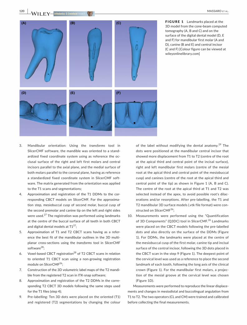
9. Pre‐labelling: Ten 3D dots were placed on the oriented (T1) and registered (T2) segmentations by changing the colour
of the label without modifying the dental anatomy.29 The dots were positioned at the mandibular central incisor that showed more displacement from T1 to T2 (centre of the root at the apical third and central point of the incisal surface), right and left mandibular first molars (centre of the mesial root at the apical third and central point of the mesiobuccal cusp) and canines (centre of the root at the apical third and central point of the tip) as shown in Figure 1 (A, B and C). The centre of the root at the apical third at T1 and T2 was selected instead of the apex, to avoid possible root's dilac-erations and/or resorptions. After pre‐labelling, the T1 and T2 mandibular 3D surface models (.vtk file format) were con-structed on SlicerCMF26;
10. Measurements were performed using the “Quantification of 3D Components” (Q3DC) tool in SlicerCMF.26 Landmarks were placed on the CBCT models following the pre‐labelled dots and also directly on the surface of the DDMs (Figure 1). For DDMs, the landmarks were placed at the centre of the mesiobuccal cusp of the first molar, canine tip and incisal surface of the central incisor, following the 3D dots placed in the CBCT scan in the step 9 (Figure 1). The deepest point of the cervical level was used as a reference to place the second landmark of each tooth, following the long axis of the clinical crown (Figure 1). For the mandibular first molars, a projec-tion of the mesial groove at the cervical level was chosen (Figure 1D).
Measurements were performed to reproduce the linear displace-ments and changes in mesiodistal and buccolingual angulation from T1 to T2. The two operators (CL and CM) were trained and calibrated before collecting the final measurements.
F I G U R E 1 Landmarks placed at the 3D model from the cone‐beam computed tomography (A, B and C) and on the surface of the digital dental model (D, E and F) for mandibular first molar (A and D), canine (B and E) and central incisor (C and F) [Colour figure can be viewed at wileyonlinelibrary.com]
(A) (B) (C)
(D) (E) (F)
| 121MASSARO et Al.
2.1 | Statistical analysis
To evaluate the intra‐rater agreement of DDM and CBCT meth-ods, rater 1 (CL) repeated all the measurements within an interval of 2 weeks. It was tested by using the intraclass correlation coeffi-cient (ICC) based on a single rater, using absolute agreement at a 95% confidence interval. To determine the inter‐rater agreement, rater 2 (CM) measured the same sample and the comparison between rater 1 and rater 2 was performed by ICC, following the same specifica-tions used for the intra‐rater ICC.
Kolmogorov‐Smirnov tests showed a non‐normal distribution for most of the variables of the study and non‐parametric tests were performed to compare DDM and CBCT methods.
Wilcoxon's test (P < .05) and ICC were used to compare the mea-surements from DDM and CBCT models (P < .05). Bland‐Altman plots were used to illustrate the comparison between DDM and CBCT assessment. All statistical analyses were performed by using IBM SPSS Statistics for Mac, version 24.0 (IBM Corp.).
3 | RESULTS
All variables had a good to excellent intra and inter‐rater agreement for measurements of both DDM and CBCT methods, with values slightly greater for the CBCT methods (Tables S1 and S2). The in-traclass correlation coefficients varied from 0.800 to 1.000 for intra‐rater agreement (Table S1) and from 0.794 to 1.000 for inter‐rater agreement (Table S2). The Wilcoxon test showed no difference when comparing left and right sides, so data were pooled together for subsequent analyses.
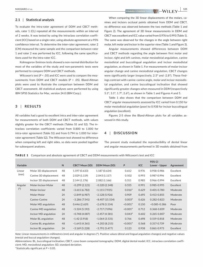
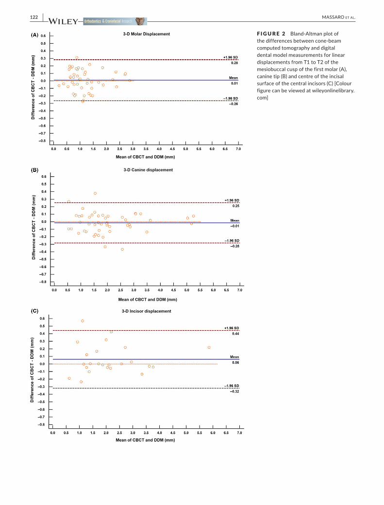
When comparing the 3D linear displacements of the molars, ca-nines and incisors occlusal points obtained from DDM and CBCT, no difference was observed between the two methods (Table 1 and Figure 2). The agreement of 3D linear measurements in DDM and CBCT was excellent and ICC value varied from 0.976 to 0.993 (Table 1). The same was observed for the changes in the angle between right molar, left molar and incisor in the superior view (Table 1 and Figure 3).
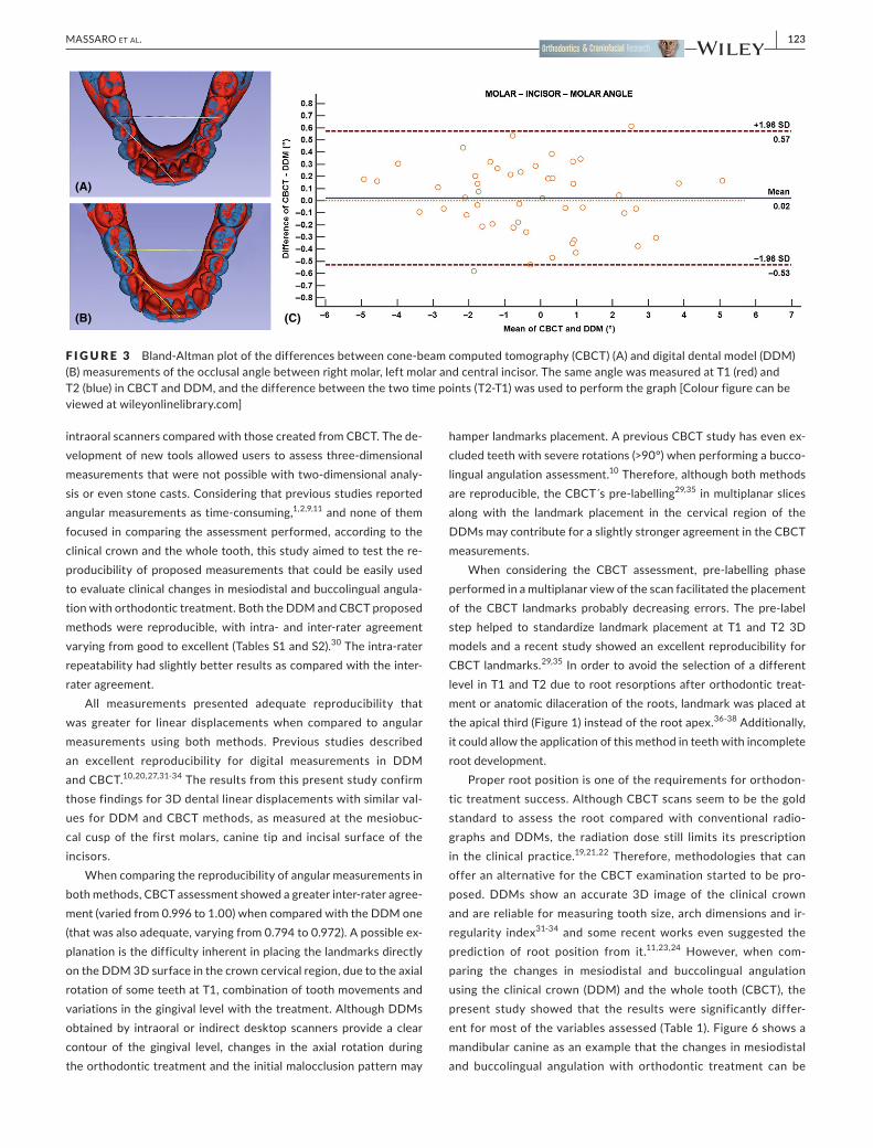
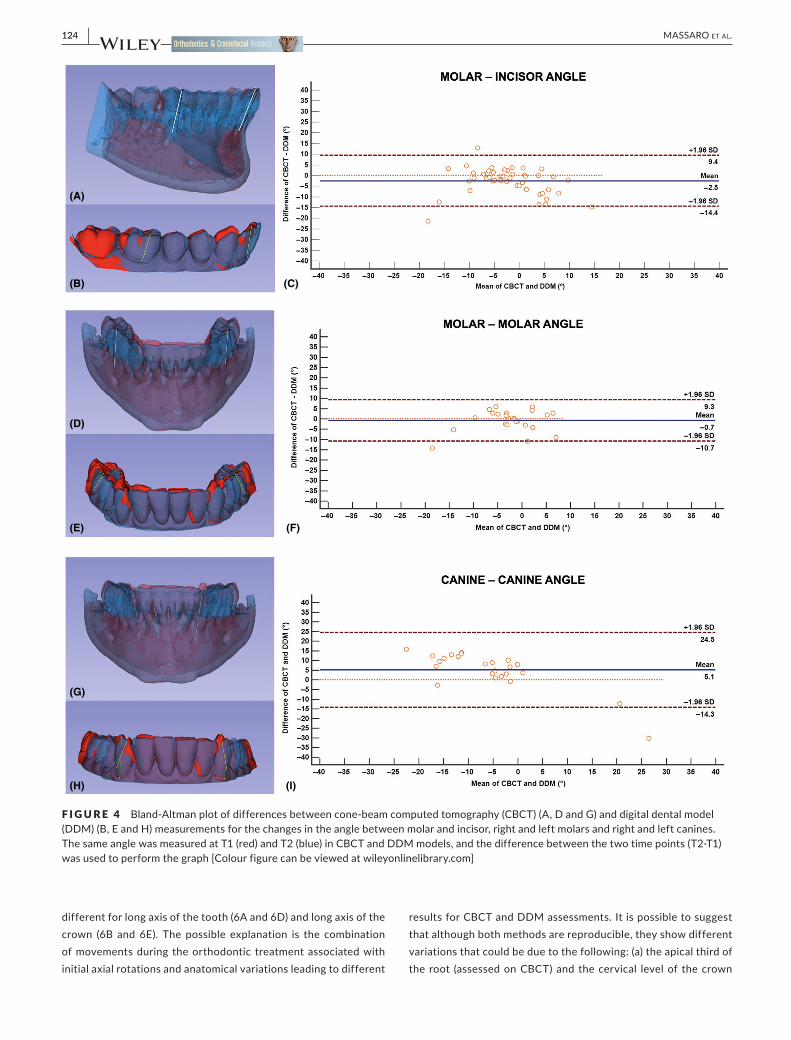
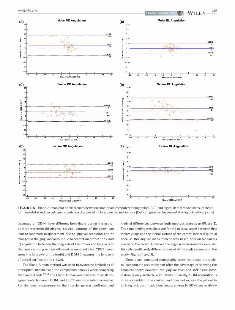
Angular measurements showed differences between DDM and CBCT methods regarding the angle between first molar and incisor, right and left canines, molar mesiodistal angulation, canine mesiodistal and buccolingual angulation and incisor mesiodistal angulation, as shown in Table 1. For measurements of molar‐incisor angular change and canine mesiodistal angulation, CBCT changes were significantly larger (respectively, 2.5° and ‐2.8°). These find-ings contrast with canine‐canine angle, molar and incisor mesiodis-tal angulation, and canine buccolingual inclination that showed significantly greater changes when measured in DDM (respectively 5.1°, 3.1°, 1.7°, 2.6°), as shown in Table 1 and Figures 4 and 5.
Table 1 also shows that the comparison between DDM and CBCT angular measurements assessed by ICC varied from 0.150 for molar mesiodistal angulation (poor) to 0.938 for incisor buccolingual angulation (excellent).
Figures 2‐5 show the Bland‐Altman plots for all variables as-sessed in this study.
4 | DISCUSSION
The present study evaluated the reproducibility of dental linear and angular measurements performed in 3D models obtained from
TA B L E 1 Comparison and absolute agreement of CBCT and DDM measurements with Wilcoxon's test and ICC
Variable N CBCT Mean (SD) DDM Mean (SD) P ICC95% CI Lower ‐ Upper Agreement
Linear (mm)
Molar 3D displacement 48 1.197 (0.633) 1.187 (0.634) 0.612 0.976 0.958‐0.986 Excellent
Canine 3D displacement 48 2.029 (1.119) 2.043 (1.117) 0.502 0.993 0.987-0.996 Excellent
Incisor 3D displacement 48 2.144 (1.176) 2.082 (1.166) 0.511 0.985 0.966-0.994 Excellent
Angular (º)
Molar‐Incisor‐Molar 48 −0.299 (2.121) −0.320 (2.148) 0.555 0.991 0.985‐0.995 Excellent
Molar‐Incisor 48 −3.615 (6.782) −1.115 (7.925) 0.016a 0.629 0.401-0.780 Moderate
Molar-Molar 24 −2.849 (6.987) −2.128 (5.926) 0.909 0.695 0.413‐0.855 Moderate
Canine-Canine 24 −3.286 (7.541) −8.407 (15.534) 0.003a 0.626 0.282-0.823 Moderate
Molar MD angulation 48 0.446 (2.619) −2.678 (5.534) <0.001a 0.150 −0.085‐0.386 Poor
Canine MD angulation 48 −5.524 (5.192) −2.717 (7.096) <0.001a 0.712 0.368‐0.859 Moderate
Incisor MD angulation 24 −0.748 (4.087) −2.457 (4.581) 0.043a 0.602 0.265‐0.807 Moderate
Molar BL angulation 48 −1.42 (3.918) −1.064 (3.531) 0.766 0.698 0.519‐0.818 Moderate
Canine BL angulation 48 −1.643 (4.361) −4.203 (8.215) <0.001a 0.568 0.317-0.739 Moderate
Incisor BL angulation 24 −3.169 (5.228) −3.791 (5.477) 0.123 0.938 0.861-0.973 Excellent
Note: Linear measurements in millimetres (mm) and angular in degrees (°). Positive values (distal and lingual angulation changes) and negative values (mesial and buccal angulation changes).Abbreviations: BL, buccolingual inclination; CBCT, cone‐beam computed tomography; DDM, digital dental model; ICC, intraclass correlation coeffi-cient; MD, mesiodistal angulation; SD, standard deviation.*Statistically significant at P < 0.05.
122 | MASSARO et Al.
F I G U R E 2 Bland‐Altman plot of the differences between cone‐beam computed tomography and digital dental model measurements for linear displacements from T1 to T2 of the mesiobuccal cusp of the first molar (A), canine tip (B) and centre of the incisal surface of the central incisors (C) [Colour figure can be viewed at wileyonlinelibrary.com]
| 123MASSARO et Al.
intraoral scanners compared with those created from CBCT. The de-velopment of new tools allowed users to assess three‐dimensional measurements that were not possible with two‐dimensional analy-sis or even stone casts. Considering that previous studies reported angular measurements as time-consuming,1,2,9,11 and none of them focused in comparing the assessment performed, according to the clinical crown and the whole tooth, this study aimed to test the re-producibility of proposed measurements that could be easily used to evaluate clinical changes in mesiodistal and buccolingual angula-tion with orthodontic treatment. Both the DDM and CBCT proposed methods were reproducible, with intra‐ and inter‐rater agreement varying from good to excellent (Tables S1 and S2).30 The intra‐rater repeatability had slightly better results as compared with the inter‐rater agreement.
All measurements presented adequate reproducibility that was greater for linear displacements when compared to angular measurements using both methods. Previous studies described an excellent reproducibility for digital measurements in DDM and CBCT.10,20,27,31-34 The results from this present study confirm those findings for 3D dental linear displacements with similar val-ues for DDM and CBCT methods, as measured at the mesiobuc-cal cusp of the first molars, canine tip and incisal surface of the incisors.
When comparing the reproducibility of angular measurements in both methods, CBCT assessment showed a greater inter‐rater agree-ment (varied from 0.996 to 1.00) when compared with the DDM one (that was also adequate, varying from 0.794 to 0.972). A possible ex-planation is the difficulty inherent in placing the landmarks directly on the DDM 3D surface in the crown cervical region, due to the axial rotation of some teeth at T1, combination of tooth movements and variations in the gingival level with the treatment. Although DDMs obtained by intraoral or indirect desktop scanners provide a clear contour of the gingival level, changes in the axial rotation during the orthodontic treatment and the initial malocclusion pattern may
hamper landmarks placement. A previous CBCT study has even ex-cluded teeth with severe rotations (>90°) when performing a bucco-lingual angulation assessment.10 Therefore, although both methods are reproducible, the CBCT´s pre‐labelling29,35 in multiplanar slices along with the landmark placement in the cervical region of the DDMs may contribute for a slightly stronger agreement in the CBCT measurements.
When considering the CBCT assessment, pre‐labelling phase performed in a multiplanar view of the scan facilitated the placement of the CBCT landmarks probably decreasing errors. The pre‐label step helped to standardize landmark placement at T1 and T2 3D models and a recent study showed an excellent reproducibility for CBCT landmarks.29,35 In order to avoid the selection of a different level in T1 and T2 due to root resorptions after orthodontic treat-ment or anatomic dilaceration of the roots, landmark was placed at the apical third (Figure 1) instead of the root apex.36-38 Additionally, it could allow the application of this method in teeth with incomplete root development.
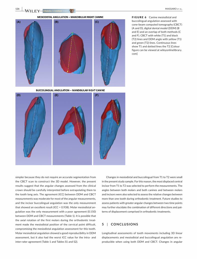
Proper root position is one of the requirements for orthodon-tic treatment success. Although CBCT scans seem to be the gold standard to assess the root compared with conventional radio-graphs and DDMs, the radiation dose still limits its prescription in the clinical practice.19,21,22 Therefore, methodologies that can offer an alternative for the CBCT examination started to be pro-posed. DDMs show an accurate 3D image of the clinical crown and are reliable for measuring tooth size, arch dimensions and ir-regularity index31-34 and some recent works even suggested the prediction of root position from it.11,23,24 However, when com-paring the changes in mesiodistal and buccolingual angulation using the clinical crown (DDM) and the whole tooth (CBCT), the present study showed that the results were significantly differ-ent for most of the variables assessed (Table 1). Figure 6 shows a mandibular canine as an example that the changes in mesiodistal and buccolingual angulation with orthodontic treatment can be
F I G U R E 3 Bland‐Altman plot of the differences between cone‐beam computed tomography (CBCT) (A) and digital dental model (DDM) (B) measurements of the occlusal angle between right molar, left molar and central incisor. The same angle was measured at T1 (red) and T2 (blue) in CBCT and DDM, and the difference between the two time points (T2‐T1) was used to perform the graph [Colour figure can be viewed at wileyonlinelibrary.com]
(A)
(B) (C)
124 | MASSARO et Al.
different for long axis of the tooth (6A and 6D) and long axis of the crown (6B and 6E). The possible explanation is the combination of movements during the orthodontic treatment associated with initial axial rotations and anatomical variations leading to different
results for CBCT and DDM assessments. It is possible to suggest that although both methods are reproducible, they show different variations that could be due to the following: (a) the apical third of the root (assessed on CBCT) and the cervical level of the crown
F I G U R E 4 Bland‐Altman plot of differences between cone‐beam computed tomography (CBCT) (A, D and G) and digital dental model (DDM) (B, E and H) measurements for the changes in the angle between molar and incisor, right and left molars and right and left canines. The same angle was measured at T1 (red) and T2 (blue) in CBCT and DDM models, and the difference between the two time points (T2‐T1) was used to perform the graph [Colour figure can be viewed at wileyonlinelibrary.com]
(A)
(B)
(D)
(E)
(G)
(H) (I)
(F)
(C)
| 125MASSARO et Al.
(assessed on DDM) have different behaviours during the ortho-dontic treatment; (b) gingival cervical contour of the tooth can lead to landmark misplacement due to gingival recession and/or changes in the gingival contour due to correction of rotations; and (c) angulation between the long axis of the crown and long axis of the root resulting in two different assessments for CBCT (mea-sures the long axis of the tooth) and DDM (measures the long axis of buccal surface of the crown).
The Bland‐Altman method was used to overcome limitations of descriptive statistics and the comparison analysis when comparing the two methods.39,40 The Bland‐Altman was sensitive to small dis-agreements between DDM and CBCT methods interchangeable. For the linear measurements, the interchange was confirmed and
minimal differences between both methods were seen (Figure 2). The same finding was observed for the occlusal angle between first molars cusps and the incisal surface of the central incisor (Figure 3) because this angular measurement was based only on landmarks placed on the crown. However, the angular measurements were sta-tistically significantly different for most of the angles assessed in the study (Figures 4 and 5).
Cone‐beam computed tomography scans reproduce the skele-tal components accurately and offer the advantage of showing the complete tooth; however, the gingival level and soft tissue infor-mation is only available with DDMs. Clinically, DDM acquisition is more accessible to the clinician and does not expose the patient to ionizing radiation. In addition, measurements in DDMs are relatively
F I G U R E 5 Bland‐Altman plot of differences between cone‐beam computed tomography CBCT and digital dental model measurements for mesiodistal and buccolingual angulation changes of molars, canines and incisors [Colour figure can be viewed at wileyonlinelibrary.com]
126 | MASSARO et Al.
simpler because they do not require an accurate segmentation from the CBCT scan to construct the 3D model. However, the present results suggest that the angular changes assessed from the clinical crown should be carefully interpreted before extrapolating them to the tooth long axis. The agreement (ICC) between DDM and CBCT measurements was moderate for most of the angular measurements, and the incisor buccolingual angulation was the only measurement that showed an excellent result (ICC = 0.938). Molar mesiodistal an-gulation was the only measurement with a poor agreement (0.150) between DDM and CBCT measurements (Table 1). It is possible that the axial rotation of the first molars during the orthodontic treat-ment made the mesiodistal position of the cervical point difficult, compromising the mesiodistal angulation assessment for this tooth. Molar mesiodistal angulation showed a good reproducibility in DDM assessment, but it also had the worst ICC value for the intra‐ and inter‐rater agreement (Table 1 and Tables S1 and S2).
Changes in mesiodistal and buccolingual from T1 to T2 were small in the present study sample. For this reason, the most displaced central incisor from T1 to T2 was selected to perform the measurements. The angles between both molars and both canines and between molars and incisors were also selected to assess the relative changes between more than one tooth during orthodontic treatment. Future studies to assess patients with greater angular changes between two time points may further elucidate the combination of different directions and pat-terns of displacement comprised in orthodontic treatments.
5 | CONCLUSIONS
Longitudinal assessments of tooth movements including 3D linear displacements and mesiodistal and buccolingual angulation are re-producible when using both DDM and CBCT. Changes in angular
F I G U R E 6 Canine mesiodistal and buccolingual angulation assessed with cone‐beam computed tomography (CBCT) (A and D), digital dental model (DDM) (B and E) and an overlap of both methods (C and F). CBCT with white (T1) and black (T2) lines and DDM angle with yellow (T1) and green (T2) lines. Continuous lines show T1 and dotted lines the T2 [Colour figure can be viewed at wileyonlinelibrary.com]
(A) (B) (C)
(D) (E) (F)
| 127MASSARO et Al.
measurements due to orthodontic treatment are discordant when measured in the digital models (clinical crown) and in the CBCT im-ages (whole tooth).
AKNOWLEDG EMENTS
São Paulo Research Foundation—FAPESP (grant No. 2018/16153‐4) due to the scholarship granted to one of the authors and NIDCR R01 DE024450 due to use of open software tools developed under this award.
ORCID
Camila Massaro https://orcid.org/0000‐0001‐6011‐7946
Lucia Cevidanes https://orcid.org/0000‐0001‐9786‐2253
Marilia Yatabe https://orcid.org/0000‐0002‐8748‐6714
Daniela Garib https://orcid.org/0000‐0002‐2449‐1620
José Roberto Pereira Lauris https://orcid.org/0000‐0003‐3475‐4479
Marcos Ioshida https://orcid.org/0000‐0002‐8852‐2051
Antonio Carlos Ruellas https://orcid.org/0000‐0001‐7973‐9286
R E FE R E N C E S
1. Andrews LF. The six keys to normal occlusion. Am J Orthod. 1972;62(3):296‐309.
2. Andrews LF. The straight‐wire appliance. Explained and compared. J Clin Orthod. 1976;10(3):174‐195.
3. Peck JL, Sameshima GT, Miller A, Worth P, Hatcher DC. Mesiodistal root angulation using panoramic and cone beam CT. Angle Orthod. 2007;77(2):206‐213.
4. Bouwens DG, Cevidanes L, Ludlow JB, Phillips C. Comparison of mesiodistal root angulation with posttreatment panoramic ra-diographs and cone‐beam computed tomography. Am J Orthod Dentofacial Orthop. 2011;139(1):126‐132.
5. Van Elslande D, Heo G, Flores‐Mir C, Carey J, Major PW. Accuracy of mesiodistal root angulation projected by cone‐beam computed tomographic panoramic‐like images. Am J Orthod Dentofacial Orthop. 2010;137(4):S94‐S99.
6. Castro IO, Frazao Gribel B, Alencar AHG, Valladares‐Neto J, Estrela C. Evaluation of crown inclination and angulation after orthodontic treatment using digital models: comparison to the prescription of the brackets used. J Orofac Orthop. 2018;79(4):227‐234.
7. Fukagawa H, Motegi E, Fuma A, et al. Tooth inclination in elderly with many remaining teeth observed by 3‐D imaging. Bull Tokyo Dent Coll. 2010;51(2):69‐76.
8. Fuma A, Motegi E, Fukagawa H, et al. Mesio‐distal tooth angulation in elderly with many remaining teeth observed by 3‐D imaging. Bull Tokyo Dent Coll. 2010;51(2):57‐64.
9. Tong H, Enciso R, Van Elslande D, Major PW, Sameshima GT. A new method to measure mesiodistal angulation and faciolin-gual inclination of each whole tooth with volumetric cone‐beam computed tomography images. Am J Orthod Dentofacial Orthop. 2012;142(1):133‐143.
10. Shewinvanakitkul W, Hans MG, Narendran S, Martin PJ. Measuring buccolingual inclination of mandibular canines and first molars using CBCT. Orthod Craniofac Res. 2011;14(3):168‐174.
11. Lee RJ, Pi S, Park J, et al. Accuracy and reliability of the ex-pected root position setup methodology to evaluate root position during orthodontic treatment. Am J Orthod Dentofacial Orthop. 2018;154(4):583‐595.
12. Vardimon AD, Lambertz W. Statistical evaluation of torque angles in reference to straight‐wire appliance (SWA) theories. Am J Orthod. 1986;89(1):56‐66.
13. Ross VA, Isaacson RJ, Germane N, Rubenstein LK. Influence of ver-tical growth pattern on faciolingual inclinations and treatment me-chanics. Am J Orthod Dentofacial Orthop. 1990;98(5):422‐429.
14. Bryant RM, Sadowsky PL, Hazelrig JB. Variability in three mor-phologic features of the permanent maxillary central incisor. Am J Orthod. 1984;86(1):25‐32.
15. Papageorgiou SN, Sifakakis I, Keilig L, et al. Torque differences ac-cording to tooth morphology and bracket placement: a finite ele-ment study. Eur J Orthod. 2017;39(4):411‐418.
16. Mestriner MA, Enoki C, Mucha JN. Normal torque of the buccal surface of mandibular teeth and its relationship with bracket po-sitioning: a study in normal occlusion. Braz Dent J. 2006;17(2): 155‐160.
17. Germane N, Bentley BE Jr, Isaacson RJ. Three biologic variables modifying faciolingual tooth angulation by straight‐wire appliances. Am J Orthod Dentofacial Orthop. 1989;96(4):312‐319.
18. Carlsson R, Ronnerman A. Crown‐root angles of upper central inci-sors. Am J Orthod. 1973;64(2):147‐154.
19. Kapila SD, Nervina JM. CBCT in orthodontics: assessment of treat-ment outcomes and indications for its use. Dentomaxillofac Radiol. 2015;44(1):20140282.
20. Kim J, Heo G, Lagravere MO. Accuracy of laser‐scanned models compared to plaster models and cone‐beam computed tomogra-phy. Angle Orthod. 2014;84(3):443‐450.
21. Ludlow JB, Davies‐Ludlow LE, Brooks SL, Howerton WB. Dosimetry of 3 CBCT devices for oral and maxillofacial radiology: CB Mercuray, NewTom 3G and i‐CAT. Dentomaxillofac Radiol. 2006;35(4):219‐226.
22. Silva MA, Wolf U, Heinicke F, Bumann A, Visser H, Hirsch E. Cone‐beam computed tomography for routine orthodontic treatment planning: a radiation dose evaluation. Am J Orthod Dentofacial Orthop. 2008;133(5):640.e1‐640.e5.
23. Staderini E, Guglielmi F, Cornelis MA, Cattaneo PM. Three‐dimen-sional prediction of roots position through cone‐beam computed tomography scans‐digital model superimposition: A novel method. Orthod Craniofac Res. 2019;22(1):16‐23.
24. de Waard O, Baan F, Verhamme L, Breuning H, Kuijpers‐Jagtman AM, Maal T. A novel method for fusion of intra‐oral scans and cone‐beam computed tomography scans for orthognathic surgery plan-ning. J Craniomaxillofac Surg. 2016;44(2):160‐166.
25. Yushkevich PA, Gerig G. ITK‐SNAP: an intractive medical image segmentation tool to meet the need for expert‐guided segmenta-tion of complex medical images. IEEE Pulse. 2017;8(4):54‐57.
26. Slicer CMF. https ://sites.google.com/a/umich.edu/denti stry‐image compu ting/Download. Accessed April 8, 2019.
27. Ioshida M, Munoz BA, Rios H, et al. Accuracy and reliability of mandibular digital model registration with use of the mucogingival junction as the reference. Oral Surg Oral Med Oral Pathol Oral Radiol. 2019;127(4):351‐360.
28. Ruellas AC, Yatabe MS, Souki BQ, et al. 3D mandibular superimpo-sition: comparison of regions of reference for voxel‐based registra-tion. PLoS ONE. 2016;11(6):e0157625.
29. Ruellas AC, Huanca Ghislanzoni LT, Gomes MR, et al. Comparison and reproducibility of 2 regions of reference for maxillary regional registration with cone‐beam computed tomography. Am J Orthod Dentofacial Orthop. 2016;149(4):533‐542.
30. Koo TK, Li MY. A guideline of selecting and reporting intraclass correlation coefficients for reliability research. J Chiropr Med. 2016;15(2):155‐163.
128 | MASSARO et Al.
31. Saleh WK, Ariffin E, Sherriff M, Bister D. Accuracy and reproduc-ibility of linear measurements of resin, plaster, digital and printed study-models. J Orthod. 2015;42(4):301‐306.
32. Dowling AH, Burns A, Macauley D, Garvey TM, Fleming GJ. Can the intra‐examiner variability of Little's Irregularity Index be improved using 3D digital models of study casts? J Dent. 2013;41(12):1271‐1280.
33. Fleming PS, Marinho V, Johal A. Orthodontic measurements on digital study models compared with plaster models: a systematic review. Orthod Craniofac Res. 2011;14(1):1‐16.
34. Cuperus AM, Harms MC, Rangel FA, Bronkhorst EM, Schols JG, Breuning KH. Dental models made with an intraoral scanner: a vali-dation study. Am J Orthod Dentofacial Orthop. 2012;142(3):308‐313.
35. de Oliveira AE, Cevidanes LH, Phillips C, Motta A, Burke B, Tyndall D. Observer reliability of three‐dimensional cephalometric land-mark identification on cone‐beam computerized tomography. Oral Surg Oral Med Oral Pathol Oral Radiol Endod. 2009;107(2):256‐265.
36. Deng Y, Sun Y, Xu T. Evaluation of root resorption after comprehen-sive orthodontic treatment using cone beam computed tomogra-phy (CBCT): a meta‐analysis. BMC Oral Health. 2018;18(1):116.
37. Lupi JE, Handelman CS, Sadowsky C. Prevalence and severity of apical root resorption and alveolar bone loss in orthodontically treated adults. Am J Orthod Dentofacial Orthop. 1996;109(1):28‐37.
38. Nabavizadeh M, Sedigh Shamsi M, Moazami F, Abbaszadegan A. Prevalence of root dilaceration in adult patients referred to shiraz dental school (2005–2010). J Dent (Shiraz). 2013;14(4):160‐164.
39. Bland JM, Altman DG. Statistical methods for assessing agree-ment between two methods of clinical measurement. Lancet. 1986;1(8476):307‐310.
40. Patcas R, Muller L, Ullrich O, Peltomaki T. Accuracy of cone‐beam computed tomography at different resolutions assessed on the bony covering of the mandibular anterior teeth. Am J Orthod Dentofacial Orthop. 2012;141(1):41‐50.
SUPPORTING INFORMATION
Additional supporting information may be found online in the Supporting Information section.
How to cite this article: Massaro C, Losada C, Cevidanes L, et al. Comparison of linear and angular changes assessed in digital dental models and cone‐beam computed tomography. Orthod Craniofac Res. 2020;23:118–128. https ://doi.org/10.1111/ocr.12352