Embed Size (px)
Citation preview

lable at ScienceDirect
Renewable Energy 111 (2017) 494e505
Contents lists avai
Renewable Energy
journal homepage: www.elsevier .com/locate/renene
Comparison of series/parallel configuration for a low-T geothermalCHP plant, coupled to thermal networks
Sarah Van Erdeweghe a, c, Johan Van Bael b, c, Ben Laenen b, William D'haeseleer a, c, *
a KU Leuven (University of Leuven), Applied Mechanics and Energy Conversion Section, Celestijnenlaan 300 - Box 2421, B-3001 Leuven, Belgiumb Flemish Institute of Technological Research (VITO), Boeretang 200, B-2400 Mol, Belgiumc EnergyVille, Thor Park, Poort Genk 8310, B-3600 Genk, Belgium
a r t i c l e i n f o
Article history:Received 2 December 2016Received in revised form4 April 2017Accepted 14 April 2017Available online 21 April 2017
Keywords:Low-grade geothermal energyCHPORCFourth generation thermal networks
* Corresponding author. KU Leuven (University ofand Energy Conversion Section, Celestijnenlaan 300Belgium.
E-mail address: [email protected] (
http://dx.doi.org/10.1016/j.renene.2017.04.0310960-1481/© 2017 Elsevier Ltd. All rights reserved.
a b s t r a c t
In this paper, the performance of a low-temperature (130 �C) geothermally-fed combined heat-and-power (CHP) plant coupled to third and fourth generation thermal networks is investigated. The seriesand parallel CHP configurations are compared based on an exergy analysis. Whether the series or theparallel CHP has the best performance depends on the thermal network requirements. The results arediscussed for a wide range of supply (40e110 �C) and return (30e70 �C) temperatures and for threevalues of the heat demand. The heat-to-electricity conversion is done via an Organic Rankine Cycle(ORC). In general, the parallel configuration is the most appropriate for the connection to high-temperature thermal networks and the series configuration performs better for the connection tolow-temperature thermal networks. For a nominal heat demand of 6 MW, the parallel configurationconnected to a 80/60 thermal network has an exergetic plant efficiency of 41.25% which is 1.67%-ptshigher than for a pure electrical power plant. The corresponding electrical power output is 89% of thepure electrical power plant. The series configuration connected to a 50/30 thermal network has anexergetic efficiency of 42.63%, which is 3.05%-pts higher than for a pure electrical power plant andproduces the same electrical power output. An additional important finding is that for isentropic and dryORC fluids, the use of superheating might increase the electrical power output if the ORC outlet tem-perature is constrained to a relatively high value. For the investigated brine conditions and R236ea as aworking fluid, the use of superheating improves the electrical power output already for ORC outlettemperatures higher than 80 �C in case of a recuperated ORC. For the basic cycle, this is only for ORCoutlet temperatures higher than 109 �C.
© 2017 Elsevier Ltd. All rights reserved.
1. Introduction
In contrast to the highly intermittent output of wind turbinesand PV solar, deep-geothermal energy is a renewable energy sourcewhich delivers a constant heat flow to the earth surface.Geothermal electric power production might increase to 1400 TWhper year in 2050, which is 3.5% of the projected global electricityproduction. Besides, 3.9% of the final energy for heat might becovered [1].
In northwest Europe, deep-geothermal energy sources aremostly low-temperature (<150 �C) sources. For these low-
Leuven), Applied Mechanics- Box 2421, B-3001 Leuven,
W. D'haeseleer).
temperatures, the binary power plant is the most appropriate[2,3]. The Organic Rankine Cycle (ORC) is a proven technology forthe conversion of low-temperature heat to electricity [4].
ORC's are widely studied in the literature. Walraven et al. [5],Franco [6] and Li et al. [7] have studied the performance of ORC'sfed by a low-temperature geothermal source. Walraven et al. [5]optimized the performance of different types of ORC's and of theKalina cycle for low-temperature (100e150 �C) geothermal heatsources. Subcritical and transcritical cycles with one or morepressure levels were discussed as well as the effect of turbine-bleeding and a recuperated ORC cycle. They found that tran-scritical and multi-pressure subcritical ORC's are the best per-forming cycles and can achieve exergetic plant efficiencies of morethan 50%. Franco [6] has studied the ORC performance for a varyingturbine inlet temperature and pressure for a low-temperaturegeothermal energy source of 100e130 �C. He found that recuper-ated configurations show only minimal performance increase with

S. Van Erdeweghe et al. / Renewable Energy 111 (2017) 494e505 495
respect to the basic configuration, but that a (up to 20%) smallercooling surface area can be obtained. Li et al. [7] have studied theeffect of a varying working fluid mass flow rate and the imple-mentation of a recuperator on the efficiency of an ORC using R123.A geothermal source temperature of 130 �C was considered. For a6 kWoutput, they found a cycle efficiency for the recuperated cycleof 7.98%, which is 1.83%-points higher than for the basic cycle.
Dai et al. [8] have studied the ORC performance based on low-temperature (145 �C) waste heat. They optimized a subcriticalORC for 10 different working fluids and found that R236ea gives thehighest exergetic efficiency for the investigated conditions. Li et al.[9] have experimentally measured the performance of a 3.5 kWORC for heat source temperatures of 70e100 �C. They found thatthe exergy destruction in the evaporator is the largest, followed bythe condenser, and that the total exergetic efficiency is around 40%.
The energy sources for ORC applications are not limited togeothermal. Tchanche et al. [10] have presented a review of ORCapplications, including thermal solar electricity, solar thermal drivenreverse osmosis desalination, solar pond power systems, oceanthermal energy conversion, biomass CHP's, binary geothermal sys-tems and low-gradewaste heat recycling. Quoilin et al. [11] have alsopresented an overview of ORC applications from different sources,including biomass, geothermal, solar and waste heat. Besides, theyhave discussed the different types of expansion machines, heat ex-changers and pumps which can be used in the ORC cycle and thedifferent aspects which influence the choice of the working fluid.
Different ORC working fluids have been studied more thor-oughly in Refs. [12,13]. Saleh et al. [12] have performed a thermo-dynamic screening of 31 pure working fluids for ORC's, using theBACKONE equation of state.1 Chen et al. [13] have screened 35working fluids for use in ORC's. They have mentioned the impor-tance of thermodynamic & physical properties, stability, environ-mental impacts, safety& compatibility, availability and cost asmainconsiderations when selecting the working fluid.
Due to the high drilling costs of deep-geothermal power plants(up to 70% of the investment costs [11]), the overall plant efficiency,and hence the plant economics, might be increased by the com-bined production of electricity and useful heat. Some research oncombined heat-and-power plants has already been done. Rubio-Maya et al. [15] have reviewed the use of low- and medium-enthalpy geothermal sources in cascade manner around theworld. They concluded that the use of geothermal energy incascade improves the resource utilization. Li et al. [16] havecompared the series and parallel configurations of an ORC sub-system, an oil gathering and transportation heat tracing (OGTHT)subsystem and an oil recovery subsystem. The geothermal sourcetemperature was 100e150 �C. They found that the series configu-ration is preferable for high geothermal water inlet temperaturesand low heat source inlet temperatures, and just the reverse for theparallel configuration. Heberle et al. [4] have compared the seriesand parallel configurations of an ORC and heat delivery to a districtheating (DH) system by second-law analysis. They found that theseries configuration is the most efficient concept. Geothermal re-sources at a temperature level below 450 K were considered andthe DH system supply and return temperatures were 75 �C and50 �C, respectively. Habka and Ajib [17] have compared the per-formance of the parallel, the series and the ”Glewe” configurationfor a geothermal source of 100 �C. The ”Glewe” configuration is
1 “…, BACKONE is a family of physically based EOS [14], which is able to describethermodynamic properties of nonpolar, dipolar and quadrupolar fluids with goodto excellent accuracy. In BACKONE the Helmholtz energy is written as a sum ofcontributions from characteristic intermolecular interactions.” - citation fromRef. [12].
based on a series configuration of the ORC and the DH system. Butpart of the brine flow rate bypasses the ORC and mixes with theORC outlet stream to increase the brine temperature which entersthe heat exchanger of the DH system. Supply temperatures in therange of 60e90 �C for the DH system and heat demands of110e150 kW were considered. The comparison between the CHPplants has shown that the parallel configuration is more economicand the series configuration is energetically more efficient, whilethe integration according to Glewe-plant does not provide signifi-cant performance improvements. Habka and Ajib [18], furthermore,have proposed 4 new configurations for a geothermally-fed CHPplant. They have compared net power consumption and exergeticplant efficiency with the series and parallel CHP configurations andwith the ORC stand-alone plant. The working fluid was R134a.Geothermal water at 100 �C and a flow rate of 1 kg/s were assumedand heat was delivered to a DH system with supply and returntemperatures of 75 �C and 50 �C, respectively, and a heat demand of110e170 kW. For the investigated boundary conditions, the opti-mized cycles and also the series plant have better energetic per-formance than the parallel plant. All CHP configurations havehigher exergetic efficiency, while the stand-alone plant producesmore electricity.
In this paper, a low-temperature (T ¼ 130 �C) geothermally-fedCHP plant is considered, which provides heat to a DH system. Cur-rent state-of-the-art DH systems are third generation thermal net-works, with typical supply temperatures of 70e110 �C. However,future energy systems are likely to integrate renewables, (e.g. deep-geothermal) CHP production, low-energy buildings and low-temperature DH networks to go towards a more sustainable andintegrated energy system. Supply temperatures may go down to40 �C [19]. The connection to third generation thermal networks hasalready been studied in the literature, the connection to fourthgeneration thermal networks is new. Two CHP configurations areinvestigated, which are schematically presented in Fig. 1. For theseries configuration, the brine (geothermal water) delivers heat tothe ORC at high temperature and subsequently to the DH system at alower temperature. For the parallel configuration, heat is deliveredto both the DH system and the ORC at a high temperature but at alower flow rate. The goal is to compare the performance of the seriesand parallel configurations based on an exergy analysis. Rather thanfocusing on a single DH system, the optimal CHP configuration aredetermined for every combination of Tsupply in 40e110 �C and Treturnin 30e70 �C. As a case study, the results for a typical third generation80/60 and fourth generation 50/30 DH system will be discussedmore in detail. In addition, also the usefulness of a recuperator willbe discussed and we will indicate that the use of superheating fordry/isentropic working fluids might improve the electrical poweroutput for sufficiently high ORC outlet temperatures.
2. Methodology
First, the objectives and constraints are stated, followed by themodels and assumptions and the most important exergy concepts.Finally, the models are verified against modern literature.
2.1. Objectives and constraints
The objective is to maximize the electricity production of theORC while satisfying a given heat demand of the DH system. Noadditional boilers or storage facilities are considered.
The net electric power _Wnet produced by the ORC is:
_Wnet ¼ _Wthg �_Wp
hm(1)

Fig. 1. Series and parallel CHP configurations.
S. Van Erdeweghe et al. / Renewable Energy 111 (2017) 494e505496
with _Wt the turbine power, _Wp the pump power, hg the electricgenerator efficiency and hm the electric motor efficiency.
The brine temperature and pressure are Tb,in ¼ 130 �C andpb,in ¼ 40 bar(a), according to the expected brine conditions inFlanders [20]. The brine flow rate is _mb ¼ 194 kg=s.
We investigate the connection to third and fourth generationthermal networks, with imposed supply (40e110 �C) and return(30e70 �C) temperatures and a heat demand which has always tobe satisfied.
2.2. Models and assumptions
Fig. 2a shows a detailed presentation of a basic ORC. The ORCworking fluid is subsequently pressurized by the pump ð1/2Þ,evaporated in the evaporator ð2/3Þ, expanded in the turbineð3/4Þ for generating mechanical (and consequently electric) po-wer, and finally condensed back to the original liquid state in thecondenser ð4/1Þ. Fig. 2b shows the corresponding T-s diagram.
Heat transfer in the evaporator is modeled as follows:
_QORC ¼ _mb;ORC�hb;ORCin � hb;ORCout
�(2)
_QORC ¼ _mwf ðh3 � h2Þ (3)
with _QORC the heat addition to the ORC, _mb;ORC the brine flow rate inthe ORC branch and _mwf the working fluid mass flow rate. hb,ORCinand hb,ORCout are the specific enthalpies of the brine at the ORC inletand outlet, respectively, h2 and h3 the specific enthalpies of theworking fluid at state 2 and 3. Other heat exchangers are modeledin a similar way.
Fig. 2. Basic ORC and T-s diagram wit
The pump and turbine powers are calculated by:
_Wp ¼ _mwf ðh2 � h1Þ (4)
_Wt ¼ _mwf ðh3 � h4Þ (5)
The relation between inlet and outlet state for the pump andturbine are found using the corresponding isentropic efficiencies:
hp ¼ h2s � h1h2 � h1
(6)
ht ¼h4 � h3h4s � h3
(7)
Subscript s refers to the isentropic state.Mixing of two streams (only for the parallel configuration) is
modeled by:
_mbhb;out ¼ _mb;ORChb;ORCout þ _mb;DHhb;DHout (8)
_mb ¼ _mb;ORC þ _mb;DH (9)
with _mb;DH the brinemass flow rate through the DH branch, hb,DHoutthe brine specific enthalpy at the DH outlet and hb,out the remainingspecific enthalpy of the brine.
The fixed parameter values are given in Table 1. DTpinch is thepinch-point-temperature difference in the heat exchangers, thesubscripts ref and c,in indicate the reference state and the coolingwater inlet state, respectively. Furthermore, kinetic and potentialenergy differences are neglected, and we do not consider pressure
h indication of the nomenclature.

Table 1Fixed model parameters [5,21].
parameter values
T1 25 �C hm 98%DTpinch 5 �C Tref 15 �Chp 80% pref 1 bar(a)ht 85% Tc,in 15 �Chg 98% pc,in 2 bar(a)
S. Van Erdeweghe et al. / Renewable Energy 111 (2017) 494e505 497
drops in the heat exchangers.R236ea is investigated as the working fluid. Amongst others,
according to [8,13], no superheating is required for this isentropicworking fluid. However, a small degree of superheatingDTsup ¼ 0.01 �C is considered to get numerical stability. The ther-modynamic and environmental properties of R236ea are given inTable 2 [22]. Additionally, the properties of the working fluidswhich have been used in the validation (Table 3) are also given inTable 2.
2.3. Exergy analysis
The CHP plant has two useful outputs, electric power andthermal power (for short referred to as ”heat”) which is delivered tothe DH system. Taking into account the quality of heat, the thermalcycle efficiency and the brine utilization, the exergetic plant effi-ciency hex is the most appropriate performance indicator tocompare different CHP configurations:
hex ¼_ExDH þ _Wnet
_Exb;in(10)
The brine inlet flow exergy _Exb;in and the DH flow exergy _ExDHare defined as follows:
_Exb;in ¼ _mbexb;in (11)
Table 2Thermodynamic and environmental parameters of ORC working fluids [22].
MW[g/mol]
Tcrit[�C] pcrit[bar(a)]
ODP GWP atmosphericlifetime [years]
R236ea 152.04 139.3 35.0 0 1410 11R123 152.93 183.7 36.6 0.010 77 1.3R600a 58.12 134.7 36.3 0 20 0.016R245fa 134.05 154.0 36.5 0 1050 7.7
Table 3Validation of the ORC model against modern literature.
Tevap [�C] pevap [bar] Tb,out [�C] hen [%] w [kJ/kg wf] workingfluid
source
87.73 12.0 59.59 11.53 22.71 R236ea [8]87.28 11.9 59.57 11.48 22.57 R236ea [5]87.28 11.9 59.44 11.48 22.57 R236ea present83.23 5.3 68.10 11.83 24.25 R123 [8]83.00 5.3 68.02 11.80 24.18 R123 present100 15.74 e 12.02 24.18 R236ea [12]100 15.72 e 12.04 23.74 R236ea present100 19.98 e 12.12 48.96 R600a [12]100 19.86 e 12.12 48.62 R600a present100 12.67 e 12.52 29.92 R245fa [12]100 12.64 e 12.60 29.47 R245fa present
_ExDH ¼ _mDH
hexsupply � exreturn
i(12)
with _mb and _mDH the brine and DH systemmass flow rates, and thesubscripts supply and return refer to the supply and return states ofthe DH system. The specific flow exergy ex is the maximal specificwork the fluid can deliver with respect to the environment, and isgenerally defined as:
ex ¼�h� href
�� Tref
�s� sref
�(13)
with T, h and s the temperature, specific enthalpy and specific en-tropy and subscript ref refers to the reference state of theenvironment.
2.4. Model validation
The models are implemented in Python [23]. CasAdi [24] is usedas a dynamic optimization framework. The maximal net electricalpower output is found bymeans of a derivative-based optimizationusing the IpOpt solver [25] for solving the non-linear problem. Fluidproperties are called from the REFPROP 8.0 database [26].
The ORC model is validated against the results obtained by Daiet al. [8], Walraven et al. [5] and Saleh et al. [12] for the respectiveconditions. Saleh et al. use the BACKONE equation of state for thecalculation of fluid properties whereas the other references use theREFPROP database. The results are summarized in Table 3 and are
very close. hen ¼ _Wnet_QORC
and w ¼ _Wnet_mwf
are the energetic cycle efficiency
and the net specific work, respectively.The ORC cycle, and the parallel and series configuration models
are additionally validated against the results of Habka et al. [17] forthe respective conditions. The net electric power generation foreach of these configurations is compared to the result of our ownmodels (values between brackets). The results are 15.45 kW(15.18 kW) for the ORC cycle, 3.19 kW (3.08 kW) for the parallel and4.36 kW (4.20 kW) for the series configuration. All errors are within3.7%, so we can conclude that the accuracy of our models issatisfying.
3. Results
First, the performance of the pure electrical power plant isdiscussed. The performance of the parallel and the series configu-rations are discussed subsequently. The performance of the CHPconfigurations is given as a function of the DH system temperatures(Tsupply and Treturn). Multiple (but constant) values of the heat de-mand are considered: _QDH ¼ 3MW , _QDH ¼ 6MW and _QDH ¼ 9MW .Afterwards, as a case study, we elaborate more in detail on theresults for the connection to two typical types of thermal networks.A state-of-the-art third generation thermal network withTsupply ¼ 80 �C& Treturn¼ 60 �C [27] and a (future) fourth generationthermal network with Tsupply ¼ 50 �C & Treturn ¼ 30 �C [28]. Theseare also referred to as high- and low-temperature DH systems,respectively. In the discussion of the series CHP configuration wemake a small side-trip to the usefulness of a recuperator. Finally, wecompare the performance of the series and the parallel CHP con-figurations for every set of Tsupply, Treturn and _QDH .
3.1. Pure electrical power plant
For the pure electrical power plant, no district heating system isconsidered and only electrical power is generated by means of anOrganic Rankine Cycle (ORC), which was already presented in
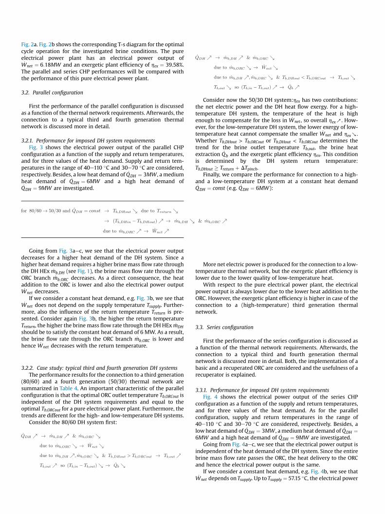
Fig. 2a. Fig. 2b shows the corresponding T-s diagram for the optimalcycle operation for the investigated brine conditions. The pureelectrical power plant has an electrical power output of_Wnet ¼ 6:18MW and an exergetic plant efficiency of hex ¼ 39.58%.The parallel and series CHP performances will be compared withthe performance of this pure electrical power plant.
3.2. Parallel configuration
First the performance of the parallel configuration is discussedas a function of the thermal network requirements. Afterwards, theconnection to a typical third and fourth generation thermalnetwork is discussed more in detail.
3.2.1. Performance for imposed DH system requirementsFig. 3 shows the electrical power output of the parallel CHP
configuration as a function of the supply and return temperatures,and for three values of the heat demand. Supply and return tem-peratures in the range of 40e110 �C and 30e70 �C are considered,respectively. Besides, a low heat demand of _QDH ¼ 3MW , a mediumheat demand of _QDH ¼ 6MW and a high heat demand of_QDH ¼ 9MW are investigated.
Going from Fig. 3aec, we see that the electrical power outputdecreases for a higher heat demand of the DH system. Since ahigher heat demand requires a higher brine mass flow rate throughthe DH HEx _mb;DH (see Fig. 1), the brine mass flow rate through theORC branch _mb;ORC decreases. As a direct consequence, the heataddition to the ORC is lower and also the electrical power output_Wnet decreases.If we consider a constant heat demand, e.g. Fig. 3b, we see that
_Wnet does not depend on the supply temperature Tsupply. Further-more, also the influence of the return temperature Treturn is pre-sented. Consider again Fig. 3b, the higher the return temperatureTreturn, the higher the brine mass flow rate through the DH HEx _mDHshould be to satisfy the constant heat demand of 6 MW. As a result,the brine flow rate through the ORC branch _mb;ORC is lower andhence _Wnet decreases with the return temperature.
3.2.2. Case study: typical third and fourth generation DH systemsThe performance results for the connection to a third generation
(80/60) and a fourth generation (50/30) thermal network aresummarized in Table 4. An important characteristic of the parallelconfiguration is that the optimal ORC outlet temperature Tb,ORCout isindependent of the DH system requirements and equal to theoptimal Tb,ORCout for a pure electrical power plant. Furthermore, thetrends are different for the high- and low-temperature DH systems.
Consider the 80/60 DH system first:
Consider now the 50/30 DH system:hex has two contributions:the net electric power and the DH heat flow exergy. For a high-temperature DH system, the temperature of the heat is highenough to compensate for the loss in _Wnet , so overall hexb. How-ever, for the low-temperature DH system, the lower exergy of low-temperature heat cannot compensate the smaller _Wnet and hexa.Whether Tb,DHout > Tb,ORCout or Tb,DHout < Tb,ORCout determines thetrend for the brine outlet temperature Tb,out, the brine heatextraction _Qb and the exergetic plant efficiency hex. This conditionis determined by the DH system return temperature:Tb,DHout � Treturn þ DTpinch.
Finally, we compare the performance for connection to a high-and a low-temperature DH system at a constant heat demand_QDH ¼ const (e.g. _QDH ¼ 6MW):
More net electric power is produced for the connection to a low-temperature thermal network, but the exergetic plant efficiency islower due to the lower quality of low-temperature heat.
With respect to the pure electrical power plant, the electricalpower output is always lower due to the lower heat addition to theORC. However, the exergetic plant efficiency is higher in case of theconnection to a (high-temperature) third generation thermalnetwork.
3.3. Series configuration
First the performance of the series configuration is discussed asa function of the thermal network requirements. Afterwards, theconnection to a typical third and fourth generation thermalnetwork is discussed more in detail. Both, the implementation of abasic and a recuperated ORC are considered and the usefulness of arecuperator is explained.
3.3.1. Performance for imposed DH system requirementsFig. 4 shows the electrical power output of the series CHP
configuration as a function of the supply and return temperatures,and for three values of the heat demand. As for the parallelconfiguration, supply and return temperatures in the range of40e110 �C and 30e70 �C are considered, respectively. Besides, alow heat demand of _QDH ¼ 3MW , a medium heat demand of _QDH ¼6MW and a high heat demand of _QDH ¼ 9MW are investigated.
Going from Fig. 4aec, we see that the electrical power output isindependent of the heat demand of the DH system. Since the entirebrine mass flow rate passes the ORC, the heat delivery to the ORCand hence the electrical power output is the same.
If we consider a constant heat demand, e.g. Fig. 4b, we see that_Wnet depends on Tsupply. Up to Tsupply ¼ 57.15 �C, the electrical power

Fig. 3. Electrical power output of the parallel CHP configuration as a function of the DHsystem requirements.
Table 4Performance of the parallel configuration for connection to a third generation 80/60and a fourth generation 50/30 thermal network, and for multiple values of the heatdemand.
Tsupply/Treturn[�C]
_QDH
[MW]Tb,out[�C]
Tb,ORCout[�C]
_Qb[MW]
_Wnet
[MW]hex [%]
80/60 3 57.59 57.15 59.06 5.83 40.416 58.03 57.15 58.71 5.48 41.259 58.48 57.15 58.34 5.13 42.08
50/30 3 56.29 57.15 60.12 5.94 39.576 55.43 57.15 60.81 5.70 39.569 54.57 57.15 61.51 5.46 39.55
S. Van Erdeweghe et al. / Renewable Energy 111 (2017) 494e505 499
output _W ¼ 6:18 MW equals the electrical power output of thepure electrical power plant. For Tsupply > 57.15 �C, the ORC heataddition is constrained by the supply temperature of the DH sys-tem. The pinch-point-temperature difference DTpinch ¼ 5 �C islocated at the supply side of DH Hex and Tb,ORCout ¼ Tsupply þ DTpinch.Furthermore, in general, _Wnet does not depend on the returntemperature. However, for high heat demands the power outputmight be constrained by Treturn. Consider Fig. 4c for the high heatdemand of _QDH ¼ 9MW . For low temperature differencesTsupply � Treturn and high values of Treturn, the brine is cooled downuntil the pinch-point-temperature difference is reached at the re-turn side of DH HEx. The pinch-point-location shifts from thesupply side to the return side of DH HEx. As a result, the ORC outlettemperature Tb,ORCout is higher and the ORC heat addition e andhence _Wnet e is lower. This reflects in the spikes in Fig. 4c. ForTsupply � Treturn ¼ 10� and Treturn � 50 �C, _Wnet is slightly lower thanthe general curve.
3.3.2. The usefulness of a recuperatorThe recuperated ORC has an extra heat exchanger in comparison
to the basic cycle. The recuperator allows internal heat recuperationin the ORC, thereby increasing the cycle efficiency. This is illustratedon the basis of Fig. 5.
In the recuperator, the temperature of the turbine outlet vapor isreduced from (4) to (4recup), and the temperature of the liquid atthe pump outlet is increased from (2) to (2recup). In the T-s dia-gram of Fig. 5b, (1) / (4recup) represents the specific coolingpower, which is smaller than (1) / (4) for the basic ORC.(2recup) / (3) represents the specific heat addition by the brine,which is also smaller than (2) / (3) for the basic ORC. The samespecific turbine power (3) / (4) can be generated for a smallerspecific brine heat addition such that the cycle efficiency is higherfor the recuperated ORC in comparison to the basic ORC.
The implementation of a recuperator is only useful in case of aconstrained ORC outlet temperature Tb,ORCout. In case of the parallelconfiguration, the ORC outlet temperature is independent of the DHsystem requirements (which can be seen in Table 4). The imple-mentation of a recuperated ORC instead of the basic onewould leadto the same electrical power output but would introduce an extracomponent (cost). Therefore, we choose for the basic ORC imple-mentation for the parallel set-up. However, in case of the seriesconfiguration, the ORC outlet temperature is constrained by Tsupplyfor Tsupply � 57.15 �C, which was explained by means of Fig. 4.Therefore, the recuperated ORC performs better forTsupply � 57.15 �C. Due to the internal heat recuperation in therecuperator, the electrical power output is higher for the same ORCheat addition.
3.3.3. Case study: typical third and fourth generation DH systemsThe performance results for the connection to a third generation
(80/60) and a fourth generation (50/30) thermal network are

Fig. 4. Electrical power output of the series CHP configuration as a function of the DHsystem requirements.
S. Van Erdeweghe et al. / Renewable Energy 111 (2017) 494e505500
summarized in Table 5. Both, the results for a basic and a recu-perated ORC implementation are given. In contrast to the parallelconfiguration, Tb,ORCout is influenced by the DH system re-quirements in case of high-temperature DH systems.
For the high-temperature DH system:
For low-temperature DH systems, Tb,ORCout is not constrained byTsupply. The optimal Tb,ORCout is the same as for a pure electrical po-wer plant. The trends are similar to those of the high-temperatureDH system.
When comparing the performance of the high-temperature tothe low-temperature DH system for a constant heat demand _QDH ¼const (e.g. _QDH ¼ 6MW):
More net electric power is produced for the connection to a low-temperature thermal network. Also the exergetic plant efficiency ishigher due to the significantly higher _Wnet.
When comparing the results of the series CHP with basic ORCwith the results for the recuperated ORC implementation, we seethat the optimal ORC outlet temperature is different. Due to theinternal heat recovery, the optimal ORC outlet temperature of therecuperated ORC is Toptb;ORCout ¼ 62:18
�C, which is higher than
Toptb;ORCout ¼ 57:15�C for the basic ORC. For the low-temperature DH
system, as a result, the brine heat extraction _Qb is lower and thebrine injection temperature Tb,out is higher in case of the recuper-ated ORC. Since the electrical power output is the same, also theexergetic plant efficiency is equal for a certain heat demand. For thehigh-temperature DH system, on the contrary, the ORC outlettemperature is constrained by Tsupplywhich leads to equal values forthe brine heat extraction and brine injection temperature. Due tothe recuperator, the electrical power output of the recuperated ORCis higher for the same heat demand, such that also the exergeticplant efficiency is higher for the recuperated series CHP.
3.4. Parallel versus series configuration
First the performance of the series and parallel configurationsare given as a function of the thermal network requirements. Fromthe summarizing figures, we can derive whether the parallel or theseries configuration has the best performance for the connection toa thermal network with imposed requirements for the supply andreturn temperatures and for the heat demand. Afterwards, we giveconclusions for the connection to a typical third and fourth gen-eration thermal network.
3.4.1. Performance for imposed DH system requirementsThe goal has been to indicate the CHP configuration with the
best performance for the connection to a (state-of-the-art) high-temperature DH system or to a (future) low-temperature DH sys-tem. Fig. 6 is summarizing the performance of the series and par-allel CHP configurations for the connection to a DH system withimposed supply & return temperatures and heat demand. Supplyand return temperatures in the range of 40e110 �C and 30e70 �Care considered, respectively, and a low ð _QDH ¼ 3MWÞ, a medium

Fig. 5. Recuperated ORC and T-s diagram with indication of the states.
S. Van Erdeweghe et al. / Renewable Energy 111 (2017) 494e505 501
ð _QDH ¼ 6MWÞ and a high ð _QDH ¼ 9MWÞ heat demand are investi-gated. The electrical power output of the pure electrical powerplant is given by the black line (at _Wnet ¼ 6:18MW).
We conclude that the parallel CHP has the best performance forthe connection to a high-temperature DH system and the seriesCHP configuration is more appropriate for the connection to a low-temperature thermal network. Heat is directly delivered to the DHsystem at high temperature in case of the parallel configuration,whereas the series configuration can keep a high electrical poweroutput when connected to a low-temperature DH system.Furthermore, from Fig. 6 follows that higher values of the heatdemand are in favor of the series configuration.
Table 5Performance of the series configuration with basic ORC and recuperated ORC forconnection to a third generation 80/60 and a fourth generation 50/30 thermalnetwork, and for multiple values of the heat demand.
Tsupply/Treturn [�C] _QDH
[MW]Tb,out[�C]
Tb,ORCout[�C]
_Qb[MW]
_Wnet
[MW]hex[%]
80/60 basic ORC 3 81.31 85 39.82 4.77 33.626 77.62 85 42.82 4.77 36.699 73.92 85 45.82 4.77 39.76
80/60 recuperatedORC
3 81.31 85 39.82 5.10 35.696 77.62 85 42.82 5.10 38.779 73.92 85 45.82 5.10 41.84
50/30 basic ORC 3 53.44 57.15 62.42 6.18 41.106 49.74 57.15 65.42 6.18 42.639 46.03 57.15 68.42 6.18 44.16
50/30 recuperatedORC
3 58.48 62.18 58.34 6.18 41.106 54.78 62.18 61.34 6.18 42.639 51.07 62.18 64.34 6.18 44.15
3.4.2. Case study: typical third and fourth generation DH systemsThe parallel configuration has the highest electrical power
output for the connection to the considered (high-temperature)third generation thermal network whereas the series configurationhas the best performance for the connection to the considered(low-temperature) fourth generation thermal network. For a heatdemand of _QDH ¼ 6MW , the parallel configuration connected to the80/60 DH system produces _Wnet ¼ 5:48MW of net electric powerand has an exergetic plant efficiency of hex ¼ 41.25%. The seriesconfiguration connected to the 50/30 DH system produces_Wnet ¼ 6:18MW of net electric power and has an exergetic plantefficiency of hex ¼ 42.63%. Because there is no limit on the ORCoutlet temperature, the ORC power generation for the seriesconfiguration connected to the low-temperature (50/30) DH sys-tem produces as much electric power as a pure electrical powerplant. However, the exergetic plant efficiency is increased fromhex¼ 39.58% to hex¼ 42.63% bymaking use of the ”ORCwaste heat”.For the parallel configuration, the power production is lower due tothe lower heat delivery to the ORC ð _mb;ORC < _mbÞ, but the exergeticplant efficiency is higher than for a pure electrical power plant:hex ¼ 41.25% versus hex ¼ 39.58%. Hereby, we prove that in bothcases the optimal CHP plant has a higher exergetic plant efficiencythan the pure electrical power plant. So, combined heat-and-powerproduction might increase the overall plant economics.
4. Discussion on the degree of superheating
The above results have been performed based on the assump-tion of no superheating (DTsup ¼ 0.01 �C for numerical stability).However, we have found that superheating might be of interest for

S. Van Erdeweghe et al. / Renewable Energy 111 (2017) 494e505502
this isentropic (slightly dry) working fluid R236ea. A degree ofsuperheating greater than zero might improve the electrical powerproduction of the ORC in case of a constrained ORC outlet tem-perature Tb,ORCout. For the basic ORC, Tb,ORCout should be higher than109 �C, but for the recuperated ORC, the performance might beimproved for much lower values of the ORC outlet temperature, i.e.for Tb,ORCout � 80 �C. For example, this means that the performanceof the recuperated series configuration for the connection to a DHsystem with Tsupply � 75 �C might be improved by usingsuperheating.
Fig. 7 shows the T-s and T-Q diagrams for the recuperated ORCwith Tb,ORCout ¼ 80 �C, Tb,ORCout ¼ 85 �C and Tb,ORCout ¼ 90 �C. It isclear that for a more stringent constraint on the ORC outlet tem-perature, the recuperator is more useful. Furthermore, byincreasing the degree of superheating, there is a better match of theheating curve of the working fluid with the brine cooling curve inthe T-Q diagram. Therefore, the electrical power output can beincreased by using superheating DTsup > 0 �C.
Additionally, Fig. 8 shows the electrical power output of therecuperated ORC, the turbine inlet temperature and the usefulnessof the recuperator as a function of the degree of superheating, andfor several values of the ORC outlet temperature Tb,ORCout. It followsfrom Fig. 8a that for Tb,ORCout ¼ 75 �C, the maximal electrical poweroutput corresponds to a superheating of 0 �C. However forTb,ORCout � 80 �C, the maximal electrical power output hasDTsup > 0 �C. Furthermore, a kink shows up in some curves for theelectrical power output. At the degree of superheating where thiskink occurs, the pinch-point-temperature of the evaporator shifts tothe brine inlet side. This can be seen in Fig. 8b because at the degreeof superheating which corresponds to the kink in the _Wnet-curve,the turbine inlet temperature reaches the temperature ofTb,in � DTpinch ¼ 125 �C. Finally, from Fig. 8c it follows that therecuperator efficiency increases with the degree of superheatingwhich was expected. From the T-s diagrams of Fig. 7 it follows thatthe turbine outlet temperature increases with the degree ofsuperheating, such that there is more potential for heat recovery. InFig. 8c, we see that the curves for the recuperator efficiency formultiple values of Tb,ORCout coincide from the degree of super-heating at the kink. From the degree of superheating which corre-sponds to the kink on, the turbine inlet temperature is the same(¼125 �C), hence for the constant turbine efficiency also the turbineoutlet temperature is the same. As a result also the recuperatorefficiency is the same for different values of Tb,ORCout.
5. Summary and conclusions
In this paper, we have compared the performance of the seriesand parallel configuration of a low-temperature geothermally-fedCHP plant, coupled to thermal networks. The performance of theseries and the parallel configuration has been shown as a functionof the supply and return temperature of the DH system. Threeconstant values for the heat demand have been considered: a lowheat demand of _QDH ¼ 3MW , a medium heat demand of_QDH ¼ 6MW and a high heat demand of _QDH ¼ 9MW . As a casestudy, two types of thermal networks have been investigated. Onthe one hand, a third generation thermal network which is today'sstate-of-the-art, and on the other hand, a fourth generation thermalnetworkwhich operates at lower temperatures and is most likely tobe introduced in future integrated and sustainable energy systems[19]. The geothermal source has a temperature of 130 �C and is
Fig. 6. Electrical power output of the parallel and the series CHP configurations as afunction of the DH system requirements.

Fig. 7. T-s and T-Q diagrams for the recuperated ORC for a constrained ORC outlet temperature.
S. Van Erdeweghe et al. / Renewable Energy 111 (2017) 494e505 503

Fig. 8. Influence of the degree of superheating on the plant performance, for multiplevalues of Tb,ORCout.
S. Van Erdeweghe et al. / Renewable Energy 111 (2017) 494e505504
available at a flow rate of 194 kg/s.Whether the parallel or the series configuration is the most
appropriate depends on the temperature levels of the DH system. Ingeneral, the parallel configuration has the best performance for highDH temperatures, whereas the series configuration performs betterfor low DH temperatures. For the considered third generation 80/60thermal network, the parallel configuration is the most appropriate.For a heat demandof _QDH ¼ 6MW , thenet electric power productionand exergetic plant efficiency are _Wnet ¼ 5:48MW and hex ¼ 41.25%,respectively. However, for the considered fourth generation 50/30thermal network, the series configuration is more appropriate. For aheat demand of _QDH ¼ 6MW , the net electric power production andexergetic plant efficiency are _Wnet ¼ 6:18MW and hex ¼ 42.63%,respectively. For the considered 50/30 thermal network, the electricpower production is as high as for a pure electrical power plant, butthe overall plant efficiency is higher due to the utilization of the ”ORCwaste heat”. For both cases considered, the exergetic plant efficiencyof the CHP plant is higher than the one for a pure electrical powerplant. So we can conclude that the combined heat-and-power pro-duction might improve the overall plant economics.
Also, the usefulness of a recuperator has been discussed. Theimplementation of a recuperated ORC is only useful when the ORCoutlet temperature is constrained. For the parallel configuration,the ORC outlet temperature does not depend on the DH systemrequirements. The parallel configuration with a recuperated ORChas the same performance as the basic ORC. However, for the seriesconfiguration, the ORC outlet temperature is constrained by thesupply temperature of the DH system. Therefore, the imple-mentation of a recuperator might be useful. For R236ea, the recu-perated ORC has a better performance for Tsupply � 57.15 �C for afixed pinch-point-temperature difference of 5 �C.
In contrast to what is often found in the literature, superheatingmight improve the ORC electrical power output for isentropic anddry working fluids. We have discussed the degree of superheatingfor the slightly dry working fluid R236ea. For the basic ORC, the ORCoutlet temperature should be constrained to a temperature higherthan 109 �C to get performance improvements. But for the recu-perated ORC, we have found that for all ORC outlet temperatureshigher than 80 �C, the electrical power output can be increased byusing superheating.
For future work, we plan to implement part-load and thermo-economic models for the CHP systems. Based on these thermo-economic (optimization) model results, we will be able tocompare the economics of the different CHP configurations.
Acknowledgments
This project receives the support of the European Union, theEuropean Regional Development Fund ERDF (936), Flanders Inno-vation & Entrepreneurship and the Province of Limburg.
Nomenclature
AbbreviationsCHP Combined Heat and PowerDH District HeatingEOS Equation Of StateORC Organic Rankine Cycle
Symbols_Ex flow exergy, [MW]ex specific flow exergy, [kJ/kg]h specific enthalpy, [kJ/kg]
S. Van Erdeweghe et al. / Renewable Energy 111 (2017) 494e505 505
_I irreversibility, [MW]_m mass flow rate, [kg/s]p pressure, [bar]_Q heat, [MW]s specific entropy, [kJ/kgK]T temperature, [�C]_W power, [MW]w specific work, [kJ/kg]h efficiency, [%]
Subscripts1 wf state at pump inlet2 wf state at pump outlet3 wf state at turbine inlet4 wf state at turbine outletb brinec cooling watercond condenseren energeticevap evaporatorex exergeticg generatorin inletm motornet netout outletp pumppinch pinch pointrecup recuperatorref reference statereturn return state DH systems isentropicsup superheatingsupply supply state DH systemt turbinewf working fluid
References
[1] IEA, Technology Roadmap - Geothermal Heat and Power, Technical Report,OECD, Paris, 2011.
[2] MIT, The Future of Geothermal Energy: Impact of Enhanced GeothermalSystems (EGS) on the United States in the 21st Century, November, 2006.Cambridge, UK.
[3] R. DiPippo, Geothermal Power Plants: Principles, Applications, Case Studiesand Environmental Impact, third ed., 2005.
[4] F. Heberle, D. Brüggemann, Exergy based fluid selection for a geothermalOrganic Rankine Cycle for combined heat and power generation, Appl. Therm.Eng. 30 (2010) 1326e1332.
[5] D. Walraven, B. Laenen, W. D’haeseleer, Comparison of thermodynamic cyclesfor power production from low-temperature geothermal heat sources, Energy
Convers. Manag. 66 (2013) 220e233.[6] A. Franco, Power production from a moderate temperature geothermal
resource with regenerative Organic Rankine Cycles, Energy Sustain. Dev. 15(2011) 411e419.
[7] M. Li, J. Wang, W. He, L. Gao, B. Wang, S. Ma, Y. Dai, Construction and pre-liminary test of a low-temperature regenerative Organic Rankine Cycle (ORC)using R123, Renew. Energy 57 (2013) 216e222.
[8] Y. Dai, J. Wang, L. Gao, Parametric optimization and comparative study oforganic Rankine cycle (ORC) for low grade waste heat recovery, EnergyConvers. Manag. 50 (2009) 576e582.
[9] J. Li, G. Pei, Y. Li, D. Wang, J. Ji, Energetic and exergetic investigation of anorganic Rankine cycle at different heat source temperatures, Energy 38 (2012)85e95.
[10] B.F. Tchanche, G. Lambrinos, A. Frangoudakis, G. Papadakis, Low-grade heatconversion into power using organic Rankine cycles A review of various ap-plications, Renew. Sustain. Energy Rev. 15 (2011) 3963e3979.
[11] S. Quoilin, M.V.D. Broek, S. Declaye, P. Dewallef, V. Lemort, Techno-economicsurvey of organic rankine cycle (ORC) systems, Renew. Sustain. Energy Rev. 22(2013) 168e186.
[12] B. Saleh, G. Koglbauer, M. Wendland, J. Fischer, Working fluids for low-temperature organic Rankine cycles, Energy 32 (2007) 1210e1221.
[13] H. Chen, D.Y. Goswami, E.K. Stefanakos, A review of thermodynamic cyclesand working fluids for the conversion of low-grade heat, Renew. Sustain.Energy Rev. 14 (2010) 3059e3067.
[14] A. Müller, J. Winkelmann, J. Fischer, Backone family of equations of state: 1.Nonpolar and polar pure fluids, AIChE J. 42 (1996) 1116e1126.
[15] C. Rubio-Maya, V.M. Ambríz Díaz, E. Pastor Martínez, J.M. Belman-Flores,Cascade utilization of low and medium enthalpy geothermal resources - areview, Renew. Sustain. Energy Rev. 52 (2015) 689e716.
[16] T. Li, J. Zhu, W. Zhang, Comparative analysis of series and parallel geothermalsystems combined power, heat and oil recovery in oilfield, Appl. Therm. Eng.50 (2013) 1132e1141.
[17] M. Habka, S. Ajib, Determination and evaluation of the operation character-istics for two configurations of combined heat and power systems dependingon the heating plant parameters in low-temperature geothermal applications,Energy Convers. Manag. 76 (2013) 996e1008.
[18] M. Habka, S. Ajib, Investigation of novel, hybrid, geothermal-energizedcogeneration plants based on organic Rankine cycle, Energy 70 (2014)212e222.
[19] H. Lund, S. Werner, R. Wiltshire, S. Svendsen, J.E. Thorsen, F. Hvelplund,B.V. Mathiesen, 4th generation district heating (4GDH), Energy 68 (2014)1e11.
[20] VITO, Diepe geothermie in de Kempen: what's next?, 2017.[21] Y.-R. Li, J.-N. Wang, M.-T. Du, S.-Y. Wu, C. Liu, J.-L. Xu, Effect of pinch point
temperature difference on cost-effective performance of organic Rankinecycle, Int. J. Energy Res. 31 (2013).
[22] J. Calm, G. Hourahan, Physical, safety and environmental data for current andalternative refrigerants, in: International Congress of Refrigeration, Prague,Czech Republic.
[23] G. van Rossum, Python Tutorial, Technical Report CS-R9526, Technical Report,Centrum voor Wiskunde en Informatica (CWI), Amsterdam, 1995.
[24] J. Andersson, A General-purpose Software Framework for Dynamic Optimi-zation, Phd, Arenberg Doctoral School, KU Leuven, 2013.
[25] A. W€achter, L.T. Biegler, On the implementation of an interior-point filter line-search algorithm for large-scale nonlinear programming, Math. Program. 106(2006) 25e57.
[26] E. Lemmon, M. Huber, M. McLinden, REFPROP - Reference Fluid Thermody-namic and Transport Properties, NIST Standard Reference Database 23, 2007.
[27] H. Gadd, S. Werner, Achieving low return temperatures from district heatingsubstations, Appl. Energy 136 (2014) 59e67.
[28] EUDP, Full-scale Demonstration of Low Temperature District Heating inExisting Buildings, 2010.


![Intro to parallel and series/parallel HEV architectures ...ecee.colorado.edu/~ecen5017/lectures/CU/L12_slides.pdf · Intro to parallel and series/parallel HEV ... time [sec] Step](https://img.pdfslide.net/doc/110x75/5ffdaa80f8451c652b521e2e/intro-to-parallel-and-seriesparallel-hev-architectures-ecee-ecen5017lecturescul12slidespdf.jpg)