Embed Size (px)
Citation preview
20 Gases&InstrumentationNovember/December 2011
F e a t u r e
Comparison of Water Vapor to Ozone for growth of ALD Films
By Jeffrey Spiegelman and JonaS SundqviSt
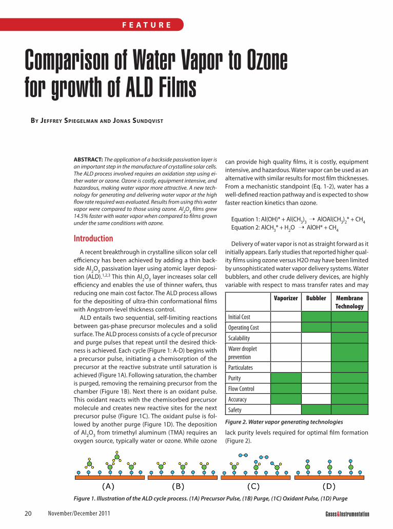
aBStraCt: The application of a backside passivation layer is an important step in the manufacture of crystalline solar cells. The ALD process involved requires an oxidation step using ei-ther water or ozone. Ozone is costly, equipment intensive, and hazardous, making water vapor more attractive. A new tech-nology for generating and delivering water vapor at the high flow rate required was evaluated. Results from using this water vapor were compared to those using ozone. Al2O3 films grew 14.5% faster with water vapor when compared to films grown under the same conditions with ozone.
IntroductionA recent breakthrough in crystalline silicon solar cell
efficiency has been achieved by adding a thin back-side Al2O3 passivation layer using atomic layer deposi-tion (ALD).1,2,3 This thin Al2O3 layer increases solar cell efficiency and enables the use of thinner wafers, thus reducing one main cost factor. The ALD process allows for the depositing of ultra-thin conformational films with Angstrom-level thickness control.
ALD entails two sequential, self-limiting reactions between gas-phase precursor molecules and a solid surface. The ALD process consists of a cycle of precursor and purge pulses that repeat until the desired thick-ness is achieved. Each cycle (Figure 1: A-D) begins with a precursor pulse, initiating a chemisorption of the precursor at the reactive substrate until saturation is achieved (Figure 1A). Following saturation, the chamber is purged, removing the remaining precursor from the chamber (Figure 1B). Next there is an oxidant pulse. This oxidant reacts with the chemisorbed precursor molecule and creates new reactive sites for the next precursor pulse (Figure 1C). The oxidant pulse is fol-lowed by another purge (Figure 1D). The deposition of Al2O3 from trimethyl aluminum (TMA) requires an oxygen source, typically water or ozone. While ozone
can provide high quality films, it is costly, equipment intensive, and hazardous. Water vapor can be used as an alternative with similar results for most film thicknesses. From a mechanistic standpoint (Eq. 1-2), water has a well-defined reaction pathway and is expected to show faster reaction kinetics than ozone.
Equation 1: Al(OH)* + Al(CH3)3 ➝ AlOAl(CH3)2* + CH4Equation 2: AlCH3* + H2O ➝ AlOH* + CH4
Delivery of water vapor is not as straight forward as it initially appears. Early studies that reported higher qual-ity films using ozone versus H2O may have been limited by unsophisticated water vapor delivery systems. Water bubblers, and other crude delivery devices, are highly variable with respect to mass transfer rates and may
lack purity levels required for optimal film formation (Figure 2).
F e a t u r e
Vaporizer Bubbler Membrane Technology
Initial Cost
Operating Cost
Scalability
Warer droplet prevention
Particulates
Purity
Flow Control
Accuracy
Safety
Figure 2. Water vapor generating technologies
Figure 1. Illustration of the ALD cycle process. (1A) Precursor Pulse, (1B) Purge, (1C) Oxidant Pulse, (1D) Purge
21www.gasesmag.com November/December 2011
F e a t u r e
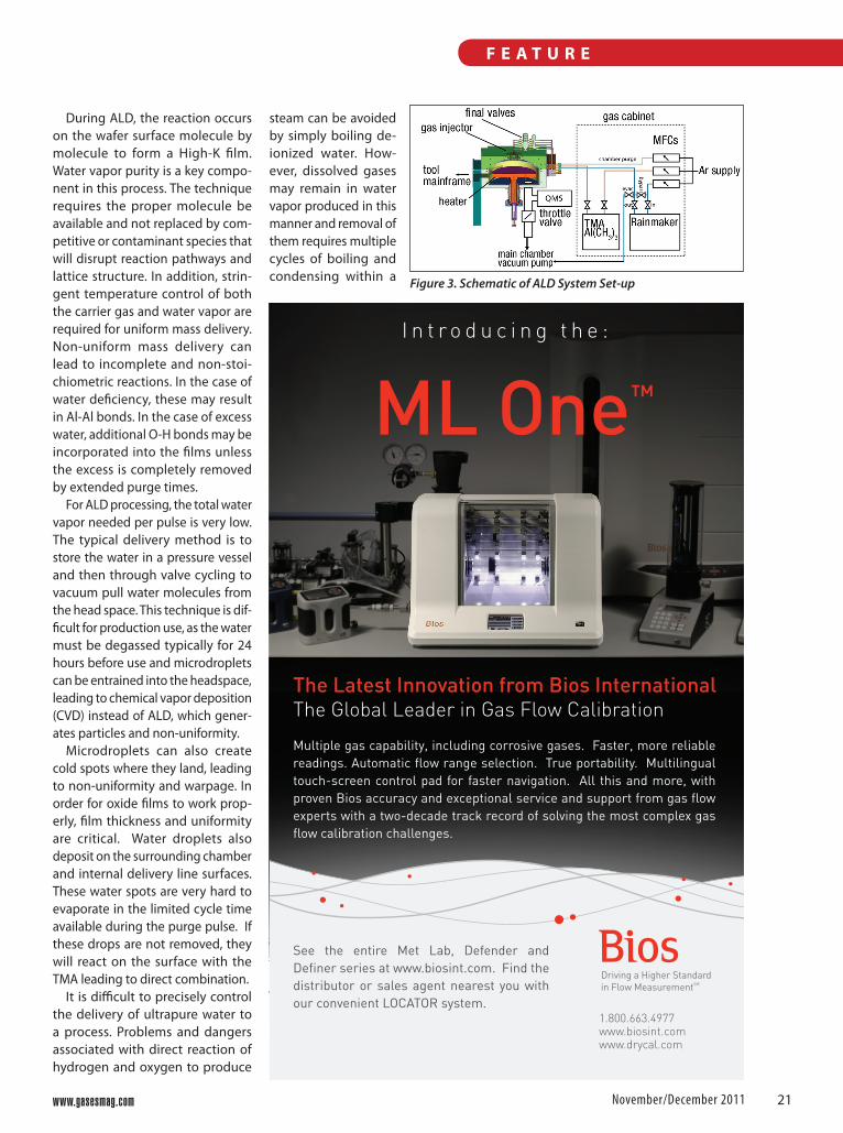
During ALD, the reaction occurs on the wafer surface molecule by molecule to form a High-K film. Water vapor purity is a key compo-nent in this process. The technique requires the proper molecule be available and not replaced by com-petitive or contaminant species that will disrupt reaction pathways and lattice structure. In addition, strin-gent temperature control of both the carrier gas and water vapor are required for uniform mass delivery. Non-uniform mass delivery can lead to incomplete and non-stoi-chiometric reactions. In the case of water deficiency, these may result in Al-Al bonds. In the case of excess water, additional O-H bonds may be incorporated into the films unless the excess is completely removed by extended purge times.
For ALD processing, the total water vapor needed per pulse is very low. The typical delivery method is to store the water in a pressure vessel and then through valve cycling to vacuum pull water molecules from the head space. This technique is dif-ficult for production use, as the water must be degassed typically for 24 hours before use and microdroplets can be entrained into the headspace, leading to chemical vapor deposition (CVD) instead of ALD, which gener-ates particles and non-uniformity.
Microdroplets can also create cold spots where they land, leading to non-uniformity and warpage. In order for oxide films to work prop-erly, film thickness and uniform ity are critical. Water droplets also deposit on the surrounding chamber and internal delivery line surfaces. These water spots are very hard to evaporate in the limited cycle time available during the purge pulse. If these drops are not removed, they will react on the surface with the TMA leading to direct combination.
It is difficult to precisely control the delivery of ultrapure water to a process. Problems and dangers associated with direct reaction of hydrogen and oxygen to produce
steam can be avoided by simply boiling de-ionized water. How-ever, dissolved gases may remain in water vapor produced in this manner and removal of them requires multiple cycles of boiling and condensing within a
Driving a Higher Standard in Flow MeasurementSM
1.800.663.4977www.biosint.comwww.drycal.com
The Latest Innovation from Bios International The Global Leader in Gas Flow Calibration
ML One™
Multiple gas capability, including corrosive gases. Faster, more reliable readings. Automatic flow range selection. True portability. Multilingual touch-screen control pad for faster navigation. All this and more, with proven Bios accuracy and exceptional service and support from gas flow experts with a two-decade track record of solving the most complex gas flow calibration challenges.
See the entire Met Lab, Defender and Definer series at www.biosint.com. Find the distributor or sales agent nearest you with our convenient LOCATOR system.
I n t r o d u c i n g t h e :
Figure 3. Schematic of ALD System Set-up
22 Gases&InstrumentationNovember/December 2011
F e a t u r e
hermetically sealed environment. In addi-tion, materials such as salts and metals can be generated during the boiling process, adding unwanted impurities. Bubblers, direct liquid injection (DLI) and vaporizers have all been used with limited success in the generation of ultrapure water vapor.
Bubblers are low cost but do not deliv-er a constant flow due to variations in temperature of the gas and liquid, oper-ating pressure, liquid level, and thermal droop. They cannot prevent entrainment of dissolved gas, volatile molecular con-taminants, and micro-droplets, which carry particulate and ionic molecular contaminants into the process. If the flow rate exceeds limited velocities, explosive bubbles blast the source liquid out of the vessel and into the downstream piping, forcing the use of phase separators that lead to increased particulates, condensa-tion, and flow instability.
Direct liquid injection has limited flow control at low flow rates and at high flow rates bubbles can appear in the liquid, gen-erating erratic values. DLI, which requires a metallic vaporizer or an additional metal hot plate to convert the liquid to gas, can vaporize only limited quantities due to thermal transfer rates, and has a potential for chemical decomposition. Most critically, it cannot provide any purification of the liquid being vaporized; everything in the liquid is vaporized into the process.
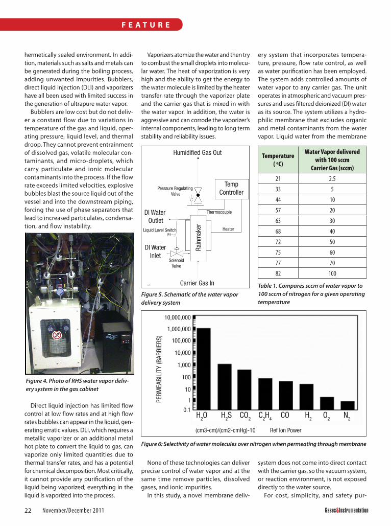
Vaporizers atomize the water and then try to combust the small droplets into molecu-lar water. The heat of vaporization is very high and the ability to get the energy to the water molecule is limited by the heater transfer rate through the vaporizer plate and the carrier gas that is mixed in with the water vapor. In addition, the water is aggressive and can corrode the vaporizer’s internal components, leading to long term stability and reliability issues.
None of these technologies can deliver precise control of water vapor and at the same time remove particles, dissolved gases, and ionic impurities.
In this study, a novel membrane deliv-
ery system that incorporates tempera-ture, pressure, flow rate control, as well as water purification has been employed. The system adds controlled amounts of water vapor to any carrier gas. The unit operates in atmospheric and vacuum pres-sures and uses filtered deionized (DI) water as its source. The system utilizes a hydro-philic membrane that excludes organic and metal contaminants from the water vapor. Liquid water from the membrane
system does not come into direct contact with the carrier gas, so the vacuum system, or reaction environment, is not exposed directly to the water source.
For cost, simplicity, and safety pur-
Heater
Rain
mak
er
Carrier Gas In
Humidified Gas Out
TempController
DI Water Outlet
DI WaterInlet
SolenoidValve
Liquid Level Switch
Pressure Regulating Valve
Thermocouple
Figure 5. Schematic of the water vapor delivery system
H2O H2S CO2 C2H4 CO H2 O2 N2
(cm3-cm)/(cm2-cmHg)-10 Ref Ion Power
PERM
EABI
LITY
(BAR
RIER
S)
10,000,000
1,000,000
100,000
10,000
1,000
100
10
1
0.1
Figure 4. Photo of RHS water vapor deliv-ery system in the gas cabinet
Figure 6: Selectivity of water molecules over nitrogen when permeating through membrane
Temperature ( ºC)
Water Vapor delivered with 100 sccm
Carrier Gas (sccm)
21 2.5
33 5
44 10
57 20
63 30
68 40
72 50
75 60
77 70
82 100
Table 1. Compares sccm of water vapor to 100 sccm of nitrogen for a given operating temperature
23www.gasesmag.com November/December 2011
F e a t u r e
poses, water is the preferred oxidant for Al2O3. To allow the successful use of ALD films in photovoltaic devices, the equipment will likely be configured as an inline atmospheric process as opposed to a vacuum-based process. An atmospheric process requires a high flow of humidi-fied gas with single percent loading with water vapor. A new membrane technol-
ogy that is capable of generating and delivering high flow rate ultrapure water vapor has been developed. The objective of this work is to determine the viability of this technology. A simple comparison with ozone was performed where films grown by both oxidants were compared for saturation rates, growth rates, unifor-mity, and particle formation.
ExperimentalALD: A 300mm vacuum ALD process
tool was set up for deposition at 300°C and the process pressure of 0.5 Torr (Figure 3). A saturation dose of trimethyl alumi-num (TMA) was predetermined using O3 as reactant. Total cycle time was in the range of 2-3 seconds. Purge pulses with argon were in the range of 0.5-1.5 seconds.
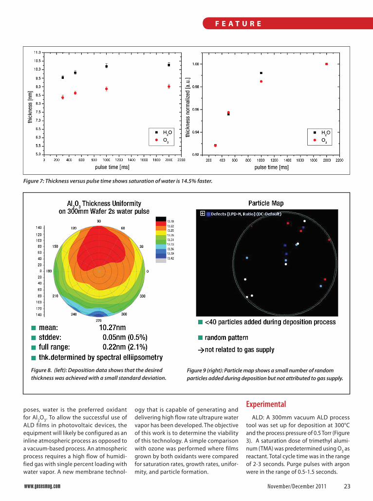
Figure 7: Thickness versus pulse time shows saturation of water is 14.5% faster.
Figure 8. (left): Deposition data shows that the desired thickness was achieved with a small standard deviation.
Figure 9 (right): Particle map shows a small number of random particles added during deposition but not attributed to gas supply.
24 Gases&InstrumentationNovember/December 2011
F e a t u r e
A unit for generating and delivering water vapor to humidify the process gas was placed in the gas cabinet (Figure 4). Pro-cess parameters included a humidifier temperature of 70°C and
H2O carrier flow of 300sccm. The humidified carrier gas flowed through the unit at a constant rate and was pulsed into the chamber by switching between final and evacuation valves. The unit was a RainMaker® Humidification System (RHS) provided by RASIRC. 100 ALD cycles of TMA/water and TMA/ozone precursors were compared. A thickness of 10nm was expected after 100 ALD cycles (1Å growth per cycle).
Water Delivery System: The carrier gas flows into the RHS where water diffuses across the hydrophilic membrane and into the carrier gas (Figure 5). The temperature of the humidified gas is measured and fed back to a temperature controller to adjust the humidification level. Internal pressure control maintains indepen-dence from variations in downstream process pressures allowing operation in atmospheric and vacuum pressure environments.
The RHS water vapor delivery system consists of a non-porous membrane that excludes particles, micro-droplets, volatile gases, and other opposite charged species from being transferred to the carrier gas and ensures only water vapor is added. The membrane is highly selective, preventing most carrier gases from crossing over into the source (Figure 6). Selectivity of up to a million to one water molecules over nitrogen has been found. Organic and metal contaminants in the liquid source cannot permeate across the membrane or enter the carrier gas stream, resulting in a water vapor saturated product that is consistent and pure.
The RHS fully saturates the carrier gas based on the temper-ature at the gas/water interface, providing accurate delivery of water vapor (Table 1). With the addition of a back pressure regulation device, low vapor pressure gases can be delivered into sub-atmospheric processes. Because the RHS works on 100% saturation of the carrier gas, the system can be cycled on and off without significant effect on accuracy as long as the maximum diffusion rate through the membrane is not exceeded.
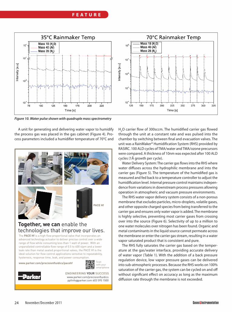
Figure 10. Water pulse shown with quadruple mass spectrometry
Scan with your smartphone
25www.gasesmag.com November/December 2011
F e a t u r e
Golden Gas Awards Deadline is January 15, 2012
Enter now at:http://www.gasesmag.com/G2A_2012web_4.pdf
ResultsInitial ALD runs found that ozone satu-
ration was observed with a pulse time of 1000 milliseconds (Figure 7). The growth rate for Al2O3 with ozone precursor was found to be ~0.9Å per cycle.
In the water test, H2O saturation was observed with a pulse time of 1000 mil-liseconds (Figure 7). The resulting film was measured by spectral ellipsometry (Figure 8). The growth rate for Al2O3 with water precursor was measured at ~1.025Å per cycle. The mean layer film thickness was 10.27nm with a standard deviation of 0.05nm (0.5%). The full range of film thickness was 0.22nm (2.1%). Particle map-ping (Figure 9) indicated that <40 particles were added during the deposition process. These occur in a random pattern, which indicates that the particles are not related to the gas supply.
During the test, the water pulse was clearly visible by quadruple mass spec-trometry. Consistent levels of water con-centration were observed over multiple pulses (Figure 10). A very strong influence of the RHS temperature on the water peak was observed. Water concentration levels increased by a factor of 10 upon increas-ing temperature from 35°C to 70°C. This is consistent with the increase in water vapor pressure between 30°C and 70°C as would be expected and demonstrates versatility in the RHS water vapor deliv-ery system with respect to water dosage concentration.
DiscussionALD tests showed the replacement of
ozone with water vapor increased the film growth rates by 14.5%. We believe this is due to the more straightforward reaction kinetics. Saturation pulse times were similar between the two oxidants as this is directly related to gas flow dynamics in the specific ALD process chamber. Film growth on the order of 1Å per cycle is similar to those reported in the literature for other water and ozone based systems.4,5 Expected layer thickness was achieved with no obvious particle issues due to water vapor supply by the RHS system.
The average layer thickness of 1.025Å for water and 0.9Å for ozone are consistent with reported literature values. A higher growth rate for water is expected. The H2O/TMA system is very efficient and self-limit-ing. The H2O/TMA reaction highly favored thermodynamically, where the enthalpy of reaction ΔH = -376kcal is one of the highest for any ALD reaction.6 Moreover, from a kinetic standpoint, this reaction can be viewed as a relatively straight for-ward proton transfer, versus that of ozone, where several reaction intermediates must be inferred in order to achieve the reac-tion product. In addition, the O3 reaction product is likely to include Al-O-Al bonds which may lead to slower reactions with the subsequent TMA step. For ALD, less reactive surface sites may lead to lower average layer thickness per cycle.
The use of the RHS allowed for easy replacement of the existing ozone oxi-dant supply and eliminated the need for degassing water before use. In research environments, the one to two day delay is acceptable before putting a water bubbler on line, but in a production environment, this is a costly throughput requirement that the RHS can eliminate.
Conclusions and Future WorkThe test demonstrates the feasibility
of the RHS water vapor delivery system for the ALD process. The expected layer thickness was achieved. Water vapor delivered in a carrier gas controlled by the RHS grew ALD films 14.5% faster than with ozone. Fast saturation compared to ozone was obtained and there were no obvious particle issues due to water vapor supply. Controlled water vapor delivery is a function of temperature control at the liquid-vapor interface. The RHS system allows for such control while providing a wide range of possible water vapor concentrations.
Future work will focus on process optimization for shorter cycle time and higher throughput. Stability and repeat-ability factors will also be addressed, where ultimately, film electrical char-acteristics with an optimized RHS water
vapor delivery system will be compared to other methods of depositing Al2O3. G&IReferences[1] B.Hoex, J.Schmidt, P. Pohl, M.C.M van de
San den, W.M.M Kessels. J. Appl. Phys. (2008), 104, 44903.
[2] J. Schmidt, R. Merkle, B. Brendel, B. Hoex, M.C.M van de Sanden, W.M.M. Kessels. Prog. Photovoltaics, (2008), 16, 461.
[3] Benick, J., Hoex, B., van de Sanden, M.C.M., Kessels, W.M.M., O. Schultz, S.W. Glunz. Appl. Phys. Lett., (2008), 92, 253504.
[4] D.N.Goldstein, J.A. McCormick, S.M. George, J. Phys. Chem. C, (2008), 112, 19530-19539.
[5] P. Poodt, V.Tiba, F. Werner, J. Schmidt, A. Vermeer, F. Roozeboom. J. Electro chem. Soc., 2011, 158, H937-H940.
[6] S. M.George. Chem. Rev. (2010), 110, 111-131
Jeffrey Spiegelman is President of rAsirC, 7815 silverton Avenue, sAn diego, CA 92126. He CAn be reACHed At 858-259-1220 or [email protected] Website WWW.rAsirC.Com
JonaS SundqviSt i s se n i o r sC i e n t i s t At frAunHofer Cnt, KönigsbrüCKer strAsse 180, 01099 dresden, germAny. He CAn be reACHed At +49 351 2607 3050 Website WWW.frAunHofer.de