Embed Size (px)
Citation preview
TurboCADThe Complete Guide to TurboCAD for Windows V4
75 Rowland Way, Novato, CA 94945. 1 800 833 4674

© 1998 by IMSI
The material presented in this publication is copyright-protected © 1998 by IMSIand may not be reproduced in any form, by any method for any purpose without the
prior written consent of IMSI. Information in this document is subject tochange without notice. It is against the law to copy the software, except in accordance with the
terms of the licensing agreement.
TurboCAD is a registered trademark of IMSI.AutoCAD is a registered trademark of Autodesk, Inc.
All other product names are acknowledged as trademarks of their respective owners.

Table of ContentsIntroduction ........................................................................................................... v1. What Is CAD? .................................................................................................... 1
CAD Is a Versatile Software Tool ....................................................................................... 2Learning to Use TurboCAD ................................................................................................ 2What Makes a Drawing Program a CAD Program? ......................................................... 3
Precision and Accuracy ........................................................................................................... 3Automation ................................................................................................................................ 3Real Scale .................................................................................................................................. 4Coordinate Geometry ............................................................................................................... 4Vector Graphics Display .......................................................................................................... 5
2. Fundamental Elements ..................................................................................... 7Commands and Tools ......................................................................................................... 7Objects and Entities ........................................................................................................... 8Launching TurboCAD ........................................................................................................ 8The TurboCAD Desktop ................................................................................................... 10Units and Scale ..................................................................................................................11Cursors and Crosshairs ................................................................................................... 12Create a Simple Drawing .................................................................................................. 12
Snaps Ensure Accuracy ........................................................................................................ 13Delete Line .............................................................................................................................. 13Using Fly-out Toolbars ........................................................................................................... 14Using the Coordinate Fields .................................................................................................. 15Using the Edit Bar................................................................................................................... 16Draw a Rectangle .................................................................................................................... 16Save the Drawing .................................................................................................................... 18If You Make a Mistake ............................................................................................................. 18
3. The First Law of CAD ...................................................................................... 21The Extra Square Inch ...................................................................................................... 21New Features in This Exercise ........................................................................................ 23

The Complete Guide to TurboCAD for Windows V4
i i
Preparation for Drawing ................................................................................................... 23Modify Paper Space ............................................................................................................... 24
Draw Polygon ‘A’ ............................................................................................................... 25Selecting Objects .............................................................................................................. 27Creating Groups ................................................................................................................ 29Creating and Using Symbols ........................................................................................... 30Saving the First Polygon as a Symbol ............................................................................ 31Creating the Second Puzzle Piece .................................................................................. 33Assembling the Puzzle ..................................................................................................... 36
Place the First Puzzle Piece .................................................................................................. 36Rotating a Selection ............................................................................................................... 37Place and Rotate the Second Puzzle Piece .......................................................................... 38Place the First Triangle .......................................................................................................... 39Complete the Square.............................................................................................................. 40
Assemble the Rectangle Puzzle ...................................................................................... 41Positive and Negative Scale .................................................................................................. 42Positive and Negative Rotation ............................................................................................. 42
The Solution ...................................................................................................................... 47Moving On .......................................................................................................................... 47
4. Keeping Design Simple .................................................................................. 49The Design Environment .................................................................................................. 50
Adjust Drawing Settings ........................................................................................................ 50Draw Three Circles ................................................................................................................. 53Draw Gear Tooth ..................................................................................................................... 54Explode Rectangle ................................................................................................................. 56Trim and Delete Lines to Finish Tooth .................................................................................. 57Copy Tooth Around the Circle ............................................................................................... 58Draw the Exposure Plate ....................................................................................................... 60Graft Double Line to Circles .................................................................................................. 62Mirror Copy to Finish Cartridge ............................................................................................ 63
Looking for Design Technique Clues ........................................................................... 64Practice Makes Perfect ..................................................................................................... 65
5. The Designer View .......................................................................................... 67Rubberbanding.................................................................................................................. 68Snaps.................................................................................................................................. 68
Snaps and the Local Menu .................................................................................................... 69Combining Snap Modes ......................................................................................................... 70
Magnetic Point ................................................................................................................... 70

Introduction
i i i
Aperture ............................................................................................................................. 71Ortho Mode ........................................................................................................................ 71The Coordinate Plane ....................................................................................................... 72
Cartesian Coordinates ........................................................................................................... 72Drawing with Coordinate Systems ....................................................................................... 74
Views of the Drawing Space ........................................................................................... 75Zooming .................................................................................................................................. 75Panning.................................................................................................................................... 76Construction Technique: Divide the Area of a Triangle ...................................................... 77A Better View of the Action .................................................................................................... 81
6. Introduction to Drawing Techniques ............................................................. 83Basic Definitions ............................................................................................................... 83Construction Techniques ................................................................................................. 87
Bisect a Line with a Point ...................................................................................................... 87Bisect a Line with a Perpendicular Line ............................................................................... 87Draw a Line at a Specific Heading ........................................................................................ 88Bisect an Angle ....................................................................................................................... 89Divide an Angle Into Any Number of Parts ........................................................................... 90Draw a Line Parallel to an Existing Line ............................................................................... 90Divide a Straight Line into Proportional Parts ..................................................................... 90Draw the Golden Mean of a Line ........................................................................................... 92Construction Lines and Circles ............................................................................................ 93Aligning Objects ..................................................................................................................... 94
Taking Advantage of Construction Techniques ............................................................ 957. Editing the CAD Drawing................................................................................ 97
Edit or Modify? .................................................................................................................. 97Modify the Divided Triangle ............................................................................................. 98Seeking Out the Details .................................................................................................... 99Explode Groups, Extract Details ................................................................................... 100Remove Unnecessary Objects ...................................................................................... 102Selection Rectangle Options ......................................................................................... 102Other Selection Options ................................................................................................. 104Select and Move Details ................................................................................................. 106Cut and Paste .................................................................................................................. 107Practice Makes Perfect ................................................................................................... 107Chamfer and Fillet ........................................................................................................... 108
Chamfer ................................................................................................................................. 108

Fillet ....................................................................................................................................... 109Meet 2 Lines..................................................................................................................... 109Cleaning Double Line Intersections...............................................................................110An Infinite Number of Uses .............................................................................................112
8. Text in the CAD Drawing............................................................................... 113An Extra Benefit for Graphic Designers ........................................................................113Text and Professional Drafting Standards ....................................................................114Placing Text in a Drawing ................................................................................................115
Editing Text in a Drawing ..................................................................................................... 116Reformatting Text in a Drawing ........................................................................................... 117Manipulating Text ................................................................................................................. 118Align Text to a Line ............................................................................................................... 120Align Text to an Arc or Circle ............................................................................................... 121Manipulating Text as Graphic Elements ............................................................................. 123Import Text from Other Applications .................................................................................. 124
The Best of Both Worlds ................................................................................................ 1269. File and Data Management ........................................................................... 129
Comparing Drawings to Documents............................................................................. 129CAD Management Systems ........................................................................................... 130Properties of Entities ...................................................................................................... 131
General Properties ............................................................................................................... 131Pen Properties ...................................................................................................................... 133Brush Properties .................................................................................................................. 134
Using Layers in a Drawing ............................................................................................. 134Using Layers to Force Standards ....................................................................................... 135
Tool-based Property Selection ...................................................................................... 136Setting the Default Properties of a Tool ............................................................................. 138Setting the Properties of Selected Objects ........................................................................ 138The Property Toolbar ........................................................................................................... 138
Choosing Among Symbols, Blocks, and Groups ........................................................ 139Organized Details Are Useful Details ............................................................................ 139
10. Drawing Techniques Part Two .................................................................. 141Arc Placement Guidelines.............................................................................................. 141
Place an Arc Along a Regular Polygon ............................................................................... 142Arc Placement Techniques ............................................................................................ 144
Arc Center and Radius ......................................................................................................... 144Concentric Arc ...................................................................................................................... 147

Double Point Arc ................................................................................................................... 149Start/Included/End (1-2-3) Arc ............................................................................................. 151
Drawing Arcs with the Edit Bar ..................................................................................... 153Drawing Tangent Arcs, Lines and Circles .................................................................... 153Using Ellipses .................................................................................................................. 160
Draw a Standard Ellipse ....................................................................................................... 160Draw a Rotated Ellipse ......................................................................................................... 161Draw an Elliptical Arc ........................................................................................................... 161Draw an Elliptical Rotated Arc ............................................................................................. 162
Curve Tools ...................................................................................................................... 162Curve Properties ............................................................................................................. 163
Using Curves to Create Parabolas and Spirals ................................................................. 163Node Editing .................................................................................................................... 167On Your Own.................................................................................................................... 168
11. Dimensioning ............................................................................................... 169Elements of Dimensioning ............................................................................................. 170
Format Property Sheets....................................................................................................... 170Dimensioning Tools ........................................................................................................ 174
Linear Dimensioning Methods ............................................................................................ 175Manual, Segment and Entity Dimensioning ....................................................................... 177Angular Dimensioning ......................................................................................................... 179Radius and Diameter Dimensioning ................................................................................... 184Leader Dimensions .............................................................................................................. 186
Professional Standards .................................................................................................. 187The Secret to Simple Dimension Formats .................................................................... 188The Seven Laws of Dimensioning ................................................................................. 188
12. Drawing Enrichment ................................................................................... 191Hatch Patterns and Solid Color Fills ............................................................................. 191
Menu: Format|Create Hatch ................................................................................................ 197Insert a Picture or Object ..................................................................................................... 197Picture and Object Edit Options .......................................................................................... 201OLE Drag and Drop .............................................................................................................. 202Paste Commands ................................................................................................................. 202
Practice Exercise ............................................................................................................ 20313. Printing and Plotting ................................................................................... 207
Printer Paper and the Drawing Sheet ........................................................................... 207Simple Printing ..................................................................................................................... 208Tiled Printing ......................................................................................................................... 209

The Complete Guide to TurboCAD for Windows V4
v i
Print Commands in the File menu ...................................................................................... 211Print Dialog ............................................................................................................................ 215
14. Drawing Import and Export ........................................................................ 217TurboCAD proprietary formats ........................................................................................... 217Drawing Exchange Format -- DXF ....................................................................................... 219DWG: AutoCAD native file format ....................................................................................... 219HP-GL and HP-GL/2: Hewlett Packard Graphics Language ............................................. 219Third-party program for file conversion ............................................................................. 220Exporting TurboCAD Drawings Using OLE Drag and Drop .............................................. 220
15. Customizing the Desktop ........................................................................... 223Why change the desktop? ............................................................................................. 223Create a personal workspace ........................................................................................ 224
Create a new toolbar ............................................................................................................ 224Add fly-out tools to the toolbar ........................................................................................... 227Create a new menu ............................................................................................................... 227Create a keyboard shortcut ................................................................................................. 229Saving customization changes ........................................................................................... 230
16. Increasing productivity ............................................................................... 231Creating and using additional views ............................................................................ 231
Using Aerial View .................................................................................................................. 232Using Viewports .................................................................................................................... 236Using Multiple Windows ...................................................................................................... 237
Measuring objects .......................................................................................................... 238Using Keyboard Shortcuts ............................................................................................ 245
Index ................................................................................................................... 247

Introduction
v i i

The Complete Guide to TurboCAD for Windows V4
v i i i

Introduction
i x
Introduction
From humble beginnings in the mid 1980s, TurboCAD has grown to become one of the toplow-cost CAD (Computer Aided Design) software products. The current version, TurboCAD4 for Windows, is filled with features that rival much more expensive products. TurboCAD 4for Windows offers much more than just a comprehensive set of drawing commands. It isnow possible to customize the program, to link drawings with files created by otherWindows programs, and to extend the capabilities of the program by writing externalsoftware programs that use TurboCAD as a drafting engine.
Learning to use a software program becomes more difficult as the complexity grows. Thisbook is written with one goal in mind: to enable you to master TurboCAD 4 for Windows aseasily as possible.
How this book is organizedThis book reveals the features of TurboCAD 4 for Windows in a natural sequence. ChapterOne offers a detailed explanation of Computer Aided Design, and why CAD software is in aclass by itself.
Chapter Two covers the TurboCAD 4 for Windows “desktop,” and how you can modify it tomatch your preferences; a theme that continues in Chapter 15. Chapters Three through Sixcover the basics of drawing, editing and modifying. (In TurboCAD, editing and modifyingrefer to making changes to previously drawn objects.) The terms editing and modifying havediffering meanings in TurboCAD 4 for Windows, and will be explained fully as the bookprogresses.
Chapters Seven through Twelve cover important topics such as dimensioning (addingmeasurements to drawings), file management, the use of hatch patterns, and specializeddrawing techniques. Chapters Thirteen and Fourteen cover printing and plotting, and usingTurboCAD 4 for Windows drawings in other software programs. The last two chapterspresent information on features new to this version of TurboCAD.

The Complete Guide to TurboCAD for Windows V4
x
Explanations, exercises, tutorialsEach command and tool in TurboCAD 4 for Windows has its own explanation. Eachcommand is introduced, typical uses are explained, followed by a hands-on sequenceshowing you how the command works. In some chapters, these hands-on explanations areprogressive, and become part of a larger exercise that continues throughout the chapter. Inother chapters, the hands-on sequences are separate. When several tools are very close toeach other in use (such as the Align tools), a common explanation is given to avoid beingredundant.
If you really want to master TurboCAD 4 for Windows, take time to follow the hands-onexercises and tutorials. It is the rare person who can read through a software manual andimmediately go to work. Most users need to practice commands and procedures, andbecome comfortable gradually. As I often tell my clients, it is one thing for your brain tounderstand a software command, but quite another for your hands to become equallyknowledgeable. The exercises and tutorials in this book bridge the gap between brain andhands.
What you needThis book makes a few assumptions about the program in use, the reader’s knowledge, andthe computer equipment available.
TurboCAD for Windows Version 4This book is based on TurboCAD 4 for Windows, published by IMSI, Inc. of San Rafael,California. The program has undergone substantial revision from previous versions, and thisbook does not attempt to cover the differences between version for and earlier releases.
Windows operating environmentThis book assumes no prior knowledge about TurboCAD 4 for Windows or about a specificmethod of drafting. It does assume that you have a basic familiarity with the Windowsoperating environment. In particular, you should know the following:
• How to start (or launch) a program;
• What directories and subdirectories are (also known as folders in Windows 95);
• What files are, and how to copy, move or delete them.
TurboCAD 4 for Windows is fully Windows 95 compliant, and complies with theMicrosoft Office standard.

Introduction
x i
Appropriate computer hardwareTurboCAD 4 for Windows requires a computer with these minimums:
• 496 or better CPU;
• 8 MB RAM recommended;
• 30 MB of free hard disk space;
• VGA graphics card or better;
• A CD-ROM drive (for installation only);
• Windows 95 or Windows NT.
SummaryThis book will help you become comfortable and productive with TurboCAD 4 forWindows. It offers explanations in real English and exercises that are practical, yet easy tofollow. This book will serve you now as you learn TurboCAD 4 for Windows, and laterwhen you need to review a command or other feature.

1What Is CAD?
Demystifying CAD
Almost all computer owners have a word processing program. They use it often, and find itvery helpful. After all, a word processor is a useful tool for a variety of tasks. Computerusers realize you don’t have to be a professional writer to make good use of aword processor.
But for some reason, many computer users assume CAD (Computer Aided Design) softwareis just for technical professionals. They don’t see themselves using the same software anarchitect or mechanical engineer uses. Ask a few computer users, and you’ll hear a varietyof excuses why they don’t have a CAD program:
• “Too complex.”
• “I don’t have any artistic ability.”
• “I don’t have a use for it.”
• “Too expensive.”
• “What’s CAD?”
All these answers point to the same fundamental problem — CAD is misunderstood.
Good CAD programs don’t have to be complex. (Yes, some are. We won’t mention nameshere.) CAD does not require artistic ability. In fact, artistic ability has nothing to do withlearning and using CAD software. As for usefulness, few programs are as versatile as a goodCAD program.
Having bought TurboCAD, you already know better than to believe CAD is expensive. Yes,there are CAD programs costing thousands of dollars, but they have features onlyprofessional engineers, architects and designers need. As for those computer users who do

The Complete Guide to TurboCAD for Windows V4
2
not know what CAD is, please gently enlighten them. After all, there was a time when youalso didn’t know CAD stands for both Computer-Aided Design and Computer-Aided Drafting.
This guidebook’s purpose is to sweep away the clouds of mystery and misunderstanding thathave surrounded CAD. If you can write with a word processor, you can draw withTurboCAD.
CAD Is a Versatile Software ToolGood software should go beyond the simple automation of an intellectual or creative taskand provide an opportunity for expanded capabilities. Spreadsheets and accountingsoftware, for example, make it possible for people without training in accounting to do theirown financial record keeping. TurboCAD provides a set of tools and an ease of use thatallows anyone to create drawings for a wide variety of applications. They are limited onlyby their design plans and their creativity.
Learn the fundamentals, and you will quickly see that TurboCAD is a versatile softwaretool. People who never dreamed of buying a drafting table have used CAD for real estateappraisal and sales, facilities planning, and arts and crafts brainstorming. The same softwareused by architects to design houses is used by storekeepers to plan retail layouts. Salesrepresentatives use CAD software on laptop computers to draw up bid specifications in thefield, and police officers prepare accident reports. Home owners are drawing remodelingplans for contractors and inspectors, saving money and communicating their ideas withprecision. The list of applications, both professional and amateur, goes on and on.
A computer is a tool kit for the mind, but too many people only have word and number toolsin their kit. TurboCAD makes the visual design tool an affordable and practical addition toany computer user’s software tool kit. Once you understand how this tool works, you’ll findmany uses for it.
Learning to Use TurboCADFor the most part, so far we’ve been talking about CAD software in general. But this book isspecifically about TurboCAD 2D for Windows Version 4. The book’s goal is to teachTurboCAD commands in a useful context, not to document capabilities without givingthought to when or where commands can be used.
Most software manuals are reference manuals, they present commands in isolation. Bycontrast, this is a handbook, where subject matter is presented in context. The Boy ScoutHandbook doesn’t just document knots, it explains when to use them. That’s an example ofcontext. We will be using a similar approach throughout this book.
So, each chapter from here on out will follow the same pattern. New commands will beintroduced and briefly explained. A tutorial project or exercise will provide an opportunityto explore the new features. Finally, each chapter ends with a review of the materialcovered.
Chapter 1 What Is Cad?
3
Take the time to follow the tutorials and work through the lessons. Your goal should be tomove from head knowledge (where you read a description and assume you understand it) tohand knowledge (where you can actually execute a command correctly).
What Makes a Drawing Program a CAD Program?A variety of software products create visual images, and they can all be lumped into thecategory of “graphics software.” CAD software belongs in this group, as well as a variety ofother programs. Several characteristics distinguish CAD software from other types ofgraphics software. These five elements are:
• Precision and accuracy
• Automation
• Real Scale
• Coordinate Geometry
• Vector Graphics display
Some graphics software products have one or two of these elements, but it takes all five tobe a true CAD program.
Precision and AccuracyCAD is meant to replace manual drafting, so it must meet the standards of those who dodrafting work. Part of the standard is mathematical precision. When you draw a line withTurboCAD, the line has an exact length, which the program can calculate to a precision ofeight decimal places. Every line, circle, etc., is on a coordinate grid, the exact location ofwhich TurboCAD stores in memory. (More about the coordinate grid later in the chapter).
When drawing by hand, it’s easy to be sloppy and let a line go an extra 1/32” or so, or tojiggle the compass when drawing a circle. But such imprecise actions are impossible inTurboCAD. A 12” line will measure exactly 12”. Circles are true, angles are exact.Commands known as Snaps allow you to attach one object to another with extremeprecision at exact locations.
AutomationCAD programs are designed to automate the manual drafting process, a demanding, labor-intensive task that has seen little automation in its several hundred years of existence. Flipthrough a textbook on manual drafting and you will see all the details that must be attendedto before one can draw a single straight line. The right diameter pencil has to be sharpenedin a certain way, the paper must be carefully attached to the drafting table, the T-Square andthe triangle placed correctly, a measurement must be taken, construction points placed, andthen finally a line can be drawn to connect the two points. Now consider drawing the same

The Complete Guide to TurboCAD for Windows V4
4
line in TurboCAD. You only have to install the program once (the equivalent of setting upthe drafting table and placing the paper). Line color, line type and line width are already set(or you can change them easily). Select the Line tool, move the cursor to the point wherethe line is to begin (perhaps using a Snap command for exact placement). Click the leftmouse button once, move the cursor to the end of the line and click again. The line is drawn,at the exact length and width, to the exact color and style.
Other graphics software products automate creating graphic images, but only a CADprogram automates drafting.
Real ScaleReal scale means that as you draw, you can use the actual dimensions of the object you arerepresenting on the screen, without regard to fitting it on the screen. When drawing a houseplan, for example, you draw a 12’ wall as a 12’ wall, not as a 6” line that represents a 12’wall.
If you have done manual drafting, you can immediately appreciate the advantages ofworking with real scale. It is no longer necessary to figure out whether to draw your plans at1/4” = 1’ or 1/2” = 6”, or whatever. Using real scale is an easier, less intimidating way ofdrafting, because you focus on your ideas, not on how to make the drawing fit the paper.TurboCAD is flexible, however, and offers the option of drawing at scale, if you prefer towork that way.
If the concept of real scale gives you trouble, perhaps the following exercise will help. Bringthe tip of your thumb and first finger together to form a circle. Put it up to one eye and usethe circle as a viewing window to look across the room. Can you see anything larger thanthe hole you’re looking through? Of course you can, and you didn’t have to calculate how toreduce the chair, the door, the window, and so forth, to fit your viewing window. TurboCADis a viewing window into your own private universe of design, and that universe can be anysize you choose. If you are drawing a 2,000-square-foot floor plan, for example, it willeasily fit onto your computer screen.
TurboCAD can easily take your real scale drawings and print them either at a scale that fitsthe page, or at a user-selected scale. For more information, see Chapter 13: Printing andPlotting.
Coordinate GeometryWhen it comes to TurboCAD 2D, Columbus was wrong: the world is flat. TurboCAD 2D'sworld is a simple, flat two-dimensional plane. Everything you draw in TurboCAD 2D willbe placed on this plane. (There is one small exception: Blocks can be optionally rotated intoa third dimension.)
Every possible location on the plane has a unique address, which can be written inX,Y coordinates. There is only one place (at any one time) in all of TurboCAD’s world thatcan have the address X 1” Y 1”. To record both the length of a line and its position on the

Chapter 1 What Is Cad?
5
plane, the only thing TurboCAD needs to know is the coordinates of each end of the line. Aline with one end exactly at X 5” Y 5” and the other end at X 11” Y 5” must be exactly 6”long, and must exist at one and only one place in the coordinate plane.
When you use TurboCAD for the first time, the coordinate display is set to show distancesin inches, with two decimal places of accuracy. As you move the pointer, the coordinatedisplay at the bottom of the screen shows the X, Y coordinate position of the cursor as itmoves across the drawing area. If the cursor is at X 10” Y 6”, then the cursor is 10 inchesabove and six inches right of a location known as the origin point. This location, near thelower left corner of the drawing area, has the coordinate address of X 0 Y 0. All othercoordinates are determined by how far they are from the origin point. Using the origin pointas a consistent point of reference for coordinate display is known in TurboCAD as AbsoluteCoordinates. Take a look at the drawing showing the origin point and some points andangles near it.
(-2,-2)
(2,3)
Points (+++++) defined in Cartesian coordinates
There is more to be learned about coordinate display; this subject will be discussed furtherin Chapter Five.
Vector Graphics DisplayA computer displays information in pixels, the little dots that make up an image on thescreen. The more pixels, the higher the resolution of the image and the smoother the image.Paint programs and other types of graphics software are limited by the number of pixelsavailable. Objects in these programs are defined by dots, so detail work can be no finer thanthe number of pixels available. Paint programs store images as a map of dots, and can’tdefine an image with detail that exceeds the number of available pixels. This is known asraster graphics, raster referring to the technology that places the pixels on the screen. Paintprograms are sometimes called device-dependent software, because the capability to createand reproduce a screen image is dependent on the display resolution in effect on the devicein use when the image was created. If you create a drawing on a low-resolution device, thenmove it to a computer with higher resolution, the image will look grainy or lumpy. The filestoring the image lacks the information necessary to display the image at the new, higherresolution. The limited information about resolution also affects printing the image. Thehigher the resolution offered by the printer, the lower the quality of the illustration if it wascreated at low resolution.
-2,-2 +
+ 2,2

The Complete Guide to TurboCAD for Windows V4
6

2Fundamental Elements
Getting Started with TurboCAD 4
This chapter will introduce the basic elements of TurboCAD, including:
• Commands and tools
• Objects and entities
• Launching TurboCAD
• The TurboCAD desktop
• Units and scale
The chapter concludes with a tutorial, which introduces the most commonly usedcommands and tools in TurboCAD.
Commands and ToolsThe terms command and tool are used in this guidebook to describe distinct types ofTurboCAD functions.
Command. Commands are functions that start and complete an event. Select All would be anexample of a command, because it immediately selects all the objects on the screen andreturns TurboCAD to its previous state, expecting no further action from you.
Tool. When you select a tool, you access a special set of functions that are available as longas the tool is active. Some tools remain active until you explicitly switch to another tool. Forexample, you can activate the Single Line tool and continue to draw lines until you switchto another tool. Other tools, such as Zoom Window, become automatically inactive as soonas you finish using them. As you begin to use the various tools in TurboCAD, notice which

The Complete Guide to TurboCAD for Windows V4
8
category they fall into. You will soon intuitively know whether a tool stays active orfunctions once and returns to an inactive state.
TIP: Think of a command like this: You tell TurboCAD what to do, and TurboCAD does it. Thinkof a tool like this: You ask TurboCAD for the means to perform an action, TurboCAD providesthe means, then you perform the action.
NOTE: Occasionally the term "tool" can also be used simply to mean a tool button on thetoolbar, or any function accessible using a tool button.
Commands and tools are accessed either by pressing a button in a toolbar, or by selectingthe command from a menu. When a menu command is being specified in this book, theinstruction will say “Menu:” followed by the name of the menu and the actual command,separated by a single line. An example would be Menu: Edit|Select All.
Occasionally the use of a command opens up a dialog box, requiring you to adjust settings,choose outcomes, etc., before the command can be executed. The use of dialogs inTurboCAD conforms to contemporary Windows standards. Specific dialogs will beexplained as required throughout the book.
Objects and EntitiesTurboCAD provides a way to draw a wide variety of objects and entities; the two terms arenot interchangeable. The term object is a general term used in this guidebook to meananything that can be displayed in a TurboCAD drawing. The term entity is used in a muchmore narrow sense, to mean a drawing object created with TurboCAD drawing tools.Entities include single lines, multilines, arcs, circles, polygons, and so forth, as well asconstruction lines and circles. TurboCAD’s entities can be combined together into groups,which are also classified as objects. Other types of TurboCAD objects include bitmaps,metafiles, OLE objects, and symbols.
Entities are independent geometric objects. They would be at home in a geometry textbook,or a manual drafting course. Objects are groups of entities, or other elements of a drawingnot easily defined using geometric definitions.
Launching TurboCADIf you have not already installed TurboCAD, do so now, following the installationinstructions in the Introduction. When you are ready to use TurboCAD, select the programusing the Start utility in Windows 95 to reach the IMSI folder. Each time you launchTurboCAD, a usage tip will appear.
✔
☞

9
Chapter 2 Fundamental Elements
Tip of the day
Note the Show Tips at Startup option in the lower left corner of the dialog box. If you do notappreciate seeing a usage tip every time you launch TurboCAD, click on the box to deselectthis option.
After the Tip of the Day dialog box, TurboCAD will display the Create from Templatedialog box. For now, choose Normal and click OK to continue.
Create from Template dialog

The Complete Guide to TurboCAD for Windows V4
10
Templates are a special type of drawing file that provide a basis for a new drawing.Templates preserve all of the settings in a drawing, such as unit and scale options, angleconventions, grid settings and colors. If in the future you find yourself using the samesettings over and over, take a minute to save those settings as a new template. Use the SaveAs command (Menu: File|Save As), and select TurboCAD Template from the list of filetypes.
The TurboCAD DesktopOnce you have chosen the Normal template you will see the TurboCAD desktop with a new,blank drawing. The next illustration shows the basic components of the TurboCAD desktopthat appears on your screen.
TurboCAD desktop
Here are brief descriptions of the various elements of the screen. The TurboCAD tutorialand help system contain additional information on the desktop elements. Most of theseelements are standard Windows features.
Menu bar Standard toolbar Insert Entity toolbar
World/Paper buttonEdit bar Ruler
Snap toolbar
Status barmessage Coordinate fields
Paper
Scroll Bars
View toolbar

11
Chapter 2 Fundamental Elements
Menu Bar. Click on the menu names on the menu bar to access TurboCAD’s commands.
Toolbars. Toolbars provide a convenient alternative to the menu system. Your screen is nowdisplaying four toolbars: the Standard and Insert Entity toolbars at the top of the screen, andthe Snap and View toolbars on the left and right sides of your screen, respectively. Clickingon any of the buttons on the toolbars will start a TurboCAD command.
TIP: TurboCAD tools are equipped with tool tips, small yellow rectangles that briefly describethe tool. To see a tool tip, place the mouse cursor on the tool and leave it there briefly.
Scroll bars. Your drawing can be larger than what you see on the screen. By clicking in thescroll bars, you can “scroll” to a different view of your drawing. Click on the arrow to scrolla small amount. Hold the mouse cursor over the “thumb” of the scroll bar (the rectangle inthe middle of the bar) and drag it to move through your drawing. Click in the area betweenthe thumb and the arrow to scroll a larger amount.
Paper. The Paper, the large white rectangle in the middle of the screen, shows you how yourdrawing will be laid out on the page when printed. You don’t have to draw on the Paper; youcan draw anywhere in the drawing space. The pattern of horizontal and vertical lines on thePaper is the grid, which marks exact locations in the drawing.
Ruler. The Ruler gives you feedback about the size and position of objects in your drawing.Notice that the unit of measure on the ruler is inches. This is the Normal template’s defaultsetting for measurement. Default means that if you don’t make a choice, the program makesthe choice for you. The ruler must display some sort of measurement, so to start with, itdisplays inches.
Edit Bar. Use the Edit Bar to draw and edit using numeric values such as lengths and angles.For example, you could tell TurboCAD to draw a line exactly two feet long, at a 45 degreeangle.
Coordinate Fields. Use the Coordinate Fields at the bottom of the screen to specify a pointin the drawing space by its exact coordinates.
Status Bar message. This message area provides a brief message describing the currentlyactive tool, or instructions about how to perform the next step in a drawing or editingprocess.
World/Paper Button. This button, in the upper-left corner of the ruler, lets you switch theruler between World space units and Paper space units of measurement, explained in thenext section. When using the Normal template there will be no difference. Using anothertemplate, such as dboard.tct, there will be a visible difference in the ruler increments. Thetwo arrows represent World units, the sheet of paper represents Paper units.
Units and ScaleThere are two distinct “spaces” in TurboCAD : World space and Paper space. The units inWorld space apply to the real-world objects you draw. The units in Paper space apply to thepaper on which your drawing will be printed. Scale in TurboCAD refers to the ratio of Paper
✔

The Complete Guide to TurboCAD for Windows V4
12
units to World units. A scale of 3/16" = 1', for example, means that an object 3/16" long inyour drawing is modeling a real-world object that is one foot long.
Think of World space as the place where you draw objects at their actual sizes. If you aredrawing a garage door, you draw it 12' wide. Think of Paper space as the place where yourdrawings shrink to fit onto a piece of paper. TurboCAD automates this shrinking process, soyou don’t have to constantly juggle real-world distances and their printed equivalents.
Normally the coordinate system, the ruler and the grid all show units in World space. Youcan switch to Paper space by clicking the World/Paper button. The Units and Scale propertysheet (found in the menu at Tools|Units and Scale) contains options for setting the drawingscale and for controlling the display of linear units. These features will be discussed indetail in Chapter Four. Normally you will use TurboCAD’s built-in templates to set updrawing space when you start a new project. The Units and Scale property sheet is for caseswhen you want to set up your units and scale manually, so we can bypass a detaileddiscussion for now.
Cursors and CrosshairsIn addition to the normal cursors provided by Windows (such as text insertion and theselection arrow), TurboCAD provides a separate cursor that appears in the drawing spacewhen a draw command is active. By default, it is a small cross. An optional full-screencrosshairs is also available. To switch between the small cross and the larger crosshairs, usethe Menu: View|Crosshairs command. The larger version is useful for lining up objects andcomparing distances using the ruler.
Selecting the drawing cursor is a matter of personal preference. Some experienced usersprefer the large crosshairs, some prefer the small cross. Try both styles and see if you have apreference for day-to-day work.
Create a Simple DrawingTake a minute now to draw a few simple shapes to represent the start of a simple floor plan.This will provide an opportunity to use several fundamental drawing commands.
1. Before you start, make sure that all the snap modes are turned off. (Snaps areexplained in the next section.) Check the Snap toolbar on the left side of the screenand make sure that the No Snap button is highlighted.
No Snap tool
2. Next, choose the Single Line tool from the Insert Entity toolbar. (Or chooseInsert|Line|Single from the menu).

13
Chapter 2 Fundamental Elements
Single Line tool
3. Now place the cursor in the bottom left portion of the drawing area and click. Byclicking you have defined the starting point of a line. As you move the mouse around,you will see a rubber band line connecting your cursor to the starting point.
TIP: Remember, if you are confused about what to do next in a command, read the status lineat the bottom of the screen.
4. Move the cursor to the upper right, and click near the top right edge of the paper, tofinish the line.
Stop and think about what was just accomplished. You drew a line across the top of thepaper, more or less of an arbitrary length. If this were to be one wall in a floor plan, does theline represent the right length of the wall? Does the line lay at the right angle in thedrawing? Unless you were very careful, have a steady hand and a sharp eye, the answer toboth questions is probably “No.” Just drawing a single line, without any extra help from theprogram, is not the best way to create a precise line to represent an object.
Snaps Ensure AccuracyTurboCAD features several snap mode commands. Snap commands allow you to draw andedit with accuracy. Two of the most commonly used snap mode commands are Snap to Gridand Vertex.
Snap to Grid (left) and Snap Vertex tools
When Snap to Grid is active, the drawing cursor can lock onto (or “snap” to) anyintersection on the drawing grid (the pattern of intersecting blue lines that you see on thePaper in the center of the drawing area.) The Vertex snap allows the drawing cursor to lockonto any endpoint of an existing line.
When a snap command is turned on, it stays active until you either click its icon to shut itoff, or click on the “no snap” icon at the top of the toolbar. More than one snap can beactive at the same time.
Use Snap to Grid in the following steps to redraw the first lines of the floor plan with greateraccuracy. First delete the existing line, then draw again.
Delete Line
1. Click the Snap to Grid tool in the Snaps toolbar.
2. Click the Select tool in the Insert Entity toolbar (above the drawing area).
✔

The Complete Guide to TurboCAD for Windows V4
14
Select tool
3. Click on the line in the drawing. The line should then be enclosed in a selectionrectangle.
Line enclosed inside selection rectangle
4. Press the <Del> key: The line disappears.
TIP: Once an object has been selected like this, you can delete it, move it, copy it, scale it orrotate it using a wide variety of techniques.
Using Fly-out ToolbarsYou are now going to use a fly-out toolbar to choose the Multiline drawing tool. Fly-outtoolbars are toolbars that “fly out” when you hold the mouse button down while the cursor isover a tool button. Tool buttons that contain fly-outs are marked by a small yellow rectanglein their lower-right corner. In this exercise use a fly-out toolbar from the Insert toolbar.
1. Position the cursor over the Single Line tool.
2. Hold down the left mouse button. Don’t let go of the mouse button until the fly-outtoolbar appears. It will look like this:
Fly-out toolbar from the Single Line tool
✔

15
Chapter 2 Fundamental Elements
3. Click on the Multiline tool.
Multiline toolbar icon
The Multiline tool is now activated, so that you can draw with it. It will remain active untilyou choose another tool.
NOTE: Notice that the button on the Insert toolbar, where the Single Line tool was, nowdisplays the Multiline tool.
1. Select Menu: View|Crosshairs to switch to a full-screen crosshairs.
2. Move the crosshairs to the upper left corner of the Paper. Click on the lower leftcorner of the first grid square inside the margin at this location. The ends of thecrosshairs should line up at 1/2" on the top ruler.
3. Move the crosshairs straight to the right until the crosshairs line up at 10" on the topmargin. Click once at this location, placing the end of the line on the lower leftcorner of the grid square, just inside the top right corner of the margin lines.
First line drawn using Multiline
Using the Coordinate FieldsDraw the next line of the rectangle using the Coordinate Fields. You’ll do this by typing theexact coordinates of the endpoint of the second line. The first endpoint of the line hasalready been established, because the Multiline tool assumes you are drawing continuous,connected lines.
1. Press <Ctrl>+<R> to activate the Coordinate Fields (bottom right corner of thedesktop).
2. Type 10 in. into the X box.
3. Press the <Tab> key to advance to the Y Coordinate Field and type 0.5 in.
4. Press <Enter> to accepts the contents of the fields. TurboCAD places the next line atprecisely 10" on the X (horizontal) axis and 1/2" on the Y (vertical) axis. A smalldiamond marks this point.
☞

The Complete Guide to TurboCAD for Windows V4
16
Using the Edit BarDraw the next line by specifying the length and angle of the line in the Edit Bar. The linewill be 9 1/2" long, going straight left from the endpoint of the second line.
1. Press <Ctrl>+<E> (or <Tab>) to activate the Edit Bar (top left portion of the desktop,just below the Standard toolbar).
2. Type -9.5 in. into the Length field. Be sure to use the <Minus> key on the keyboard,not the <Minus> key on the numeric keypad.
3. Press the <Tab> key to move to the Angle field, then type 0. The Edit bar should nowlook like this:
Edit bar showing -9.5 and 0 in fields
4. Press <Enter> to accept the contents of the Edit Bar fields.
TurboCAD draws a line 9 1/2" long, straight left from the end of the second line. Now drawone more line to create a rectangle.
1. Move the crosshairs up to the starting point of the first line. Click on the endpoint todraw a line and close the rectangle.
2. Click on the Select tool in the Insert Entity toolbar, to end drawing mode.
You have now drawn a simple rectangle using the Multiline tool (found using a fly-outtoolbar), the Snap to Grid tool, the Coordinate Fields, and the Edit Bar. These differentfeatures represent the basics of entity placement in TurboCAD. These tools and commandswill be used often throughout the rest of the book.
Draw a Rectangle
TurboCAD offers a variety of single line tools, visible when you use the fly-out toolbar. Wewill explore all features in upcoming chapters. For now we will draw one more rectangle,but this time will use the rectangle tool instead of a line tool.
The Rectangle tool enables you to create a rectangle by defining two diagonally oppositecorners. Rectangles created this way are oriented orthogonally (sides are true vertical andtrue horizontal), although they can subsequently be rotated using editing tools.
The existing rectangle on screen, drawn from four separate lines, will represent the exteriorof the perimeter walls. The new rectangle will represent the interior of the same walls. Toincrease accuracy, increase the number of squares in the grid.
1. Select Menu: Tools|Grid. Click on Advanced Grid tab. The Drawing Setup dialogappears.
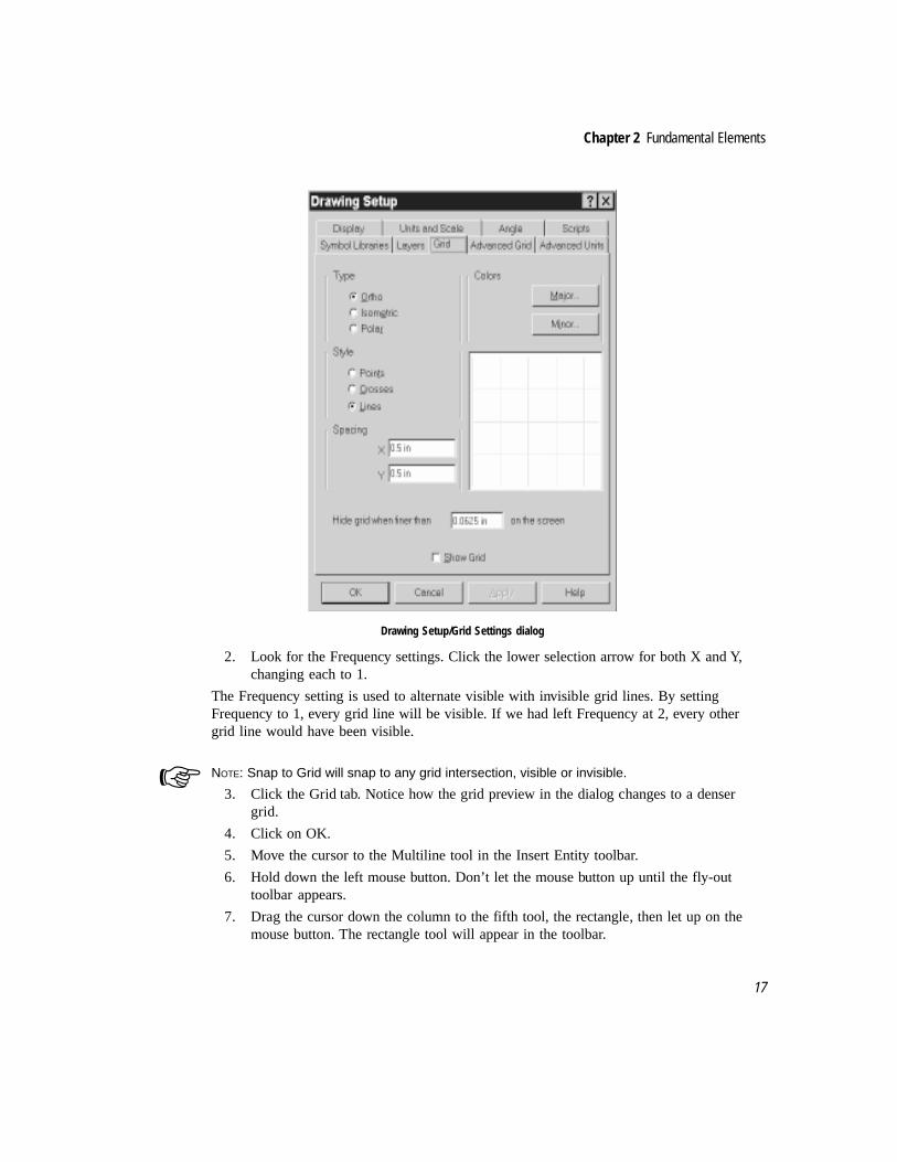
17
Chapter 2 Fundamental Elements
Drawing Setup/Grid Settings dialog
2. Look for the Frequency settings. Click the lower selection arrow for both X and Y,changing each to 1.
The Frequency setting is used to alternate visible with invisible grid lines. By settingFrequency to 1, every grid line will be visible. If we had left Frequency at 2, every othergrid line would have been visible.
NOTE: Snap to Grid will snap to any grid intersection, visible or invisible.
3. Click the Grid tab. Notice how the grid preview in the dialog changes to a densergrid.
4. Click on OK.
5. Move the cursor to the Multiline tool in the Insert Entity toolbar.
6. Hold down the left mouse button. Don’t let the mouse button up until the fly-outtoolbar appears.
7. Drag the cursor down the column to the fifth tool, the rectangle, then let up on themouse button. The rectangle tool will appear in the toolbar.
☞
The Complete Guide to TurboCAD for Windows V4
18
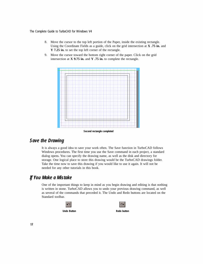
8. Move the cursor to the top left portion of the Paper, inside the existing rectangle.Using the Coordinate Fields as a guide, click on the grid intersection at X .75 in. andY 7.25 in. to set the top left corner of the rectangle.
9. Move the cursor toward the bottom right corner of the paper. Click on the gridintersection at X 9.75 in. and Y .75 in. to complete the rectangle.
Second rectangle completed
Save the DrawingIt is always a good idea to save your work often. The Save function in TurboCAD followsWindows procedures. The first time you use the Save command in each project, a standarddialog opens. You can specify the drawing name, as well as the disk and directory forstorage. One logical place to store this drawing would be the TurboCAD drawings folder.Take the time now to save this drawing if you would like to use it again. It will not beneeded for any other tutorials in this book.
If You Make a MistakeOne of the important things to keep in mind as you begin drawing and editing is that nothingis written in stone. TurboCAD allows you to undo your previous drawing command, as wellas several of the commands that preceded it. The Undo and Redo buttons are located on theStandard toolbar.
Undo Button Redo button

19
Chapter 2 Fundamental Elements
Take a few minutes to experiment with the other single-line drawing options in addition toLine, Multiline and Rectangle. Feel free to draw, delete, or save as you prefer. If you feeladventurous, try to use some of the Snap Mode commands not yet introduced.


3The First Law of CAD
Never Draw the Same Object Twice
As described in Chapter 1, CAD programs use the principles and elements of geometry tocreate objects. In this chapter you’ll construct a geometric puzzle that has baffledgenerations of math students. Drawing it will familiarize you with more TurboCADfeatures, and help you gain an understanding of when to modify existing views andfunctions. The exercise will also demonstrate TurboCAD’s keen accuracy, which will enableyou to solve the puzzle.
The Extra Square InchThe problem is simple to set up; try it using pencil, paper and scissors before you draw it inTurboCAD. Draw and cut out two copies of Polygon A and Polygon B, using the dimensionsshown. (Or photocopy the next page twice and cut out the polygons. The figures will besmaller, but proportionally correct.)

The Complete Guide to TurboCAD for Windows V4
22
Puzzle Polygons A and B with dimensions
Arrange the four polygons into a square, aligning the outside corners of the objects. There isno need for overlapping.
The four pieces arranged into a square
Next, arrange the same four polygons into a rectangle, as shown. Do not overlap the objects.Align them using the outside corners, so that the outside boundary is closed.
3B
A
3
5
8
5

Chapter 3 The First Law of CAD
23
The four pieces arranged into a rectangle
When arranged into a square, the area is 64 square inches (8" x 8" = 64 square inches). Butwhen these same polygons are arranged into a rectangle, the area is 65 square inches (5" x13" = 65 square inches.) Why? Where does the extra square inch come from? The solution isat the end of the chapter—no fair jumping ahead! Draw the puzzle in TurboCAD to see thesolution.
New Features in This ExerciseThe following new features and procedures will be introduced in this exercise:
· Change Paper scale and display
· Change the on-screen view
· Window selection of objects
· Create a group from individual objects
· Creating, saving and using symbols
· Flipping objects
· Moving an object’s reference point
Preparation for DrawingThe standard presentation of the desktop and settings in TurboCAD may not always be rightfor a particular project. As you become more familiar with TurboCAD and start using it foryour own work, you will need to consider the layout of the screen and the status of some ofthe program’s basic settings for each project. Many times you can use the default screenlayout and settings, but sometimes you will want to make changes before you draw.
For this exercise, you will modify the TurboCAD defaults for paper size, drawing scale andgroups.
By asking yourself questions about the project you wish to undertake, you will better knowwhich settings need to be changed, if any. In the case of our puzzle, you may be wonderingwhen to change the paper space.
Consider what needs to be done. You need enough room to draw the two polygons and thento place four copies of each polygon (two for the square, two for the rectangle) on-screen at

The Complete Guide to TurboCAD for Windows V4
24
the same time. You could draw outside the boundaries of the Paper, but you would lose theability to snap to the grid. And, you might find drawing outside the boundaries of the Paperdistracting, even if you used an alternate means of drawing (such as typing coordinates ordistances, as demonstrated in Chapter Two.) A simple solution is to increase the size of thePaper.
The reasons for modifying the Create Group default settings will be explained below, whenthe Create Group command is introduced.
Modify Paper SpaceThe following steps prepare the drawing area for the project.
1. Select Menu: Tools|Drawing Setup. A dialog will appear. Select the Units and Scaletab if it is not already selected.
Drawing Setup dialog
2. In the Scale section, click the selection arrow for Scale. Click on “6” = 1’-0” (HalfSize)” as displayed above.
3. Make sure “Use Paper Space Coordinates” is not selected. Click on OK.
4. Select Menu: Tools|Program Setup. A dialog will appear. Select the Desktop tab if itis not already selected.

Chapter 3 The First Law of CAD
25
Program Setup dialog
5. Deselect both Paper Display settings (Show Margins and Show Background), asillustrated above. Click OK.
Draw Polygon ‘A’Draw the first piece of the geometry puzzle.
1. Click the Zoom Extents tool in the View toolbar (right side of screen).
Zoom Extents tool icon
2. Click on Grid in the Snaps toolbar (left side of screen).
Grid Snap tool icon
3. Click on Single Line in the Insert Entity toolbar (top of screen).

The Complete Guide to TurboCAD for Windows V4
26
Single Line tool icon
4. Move the drawing cursor to the top left portion of the paper, and click on a gridintersection to start a line.
5. Using the grid and Edit Bar as a reference, draw a 5” line straight down the sheet.Each thicker blue line of the grid represents a distance of 1”.
Drawing the first line
6. Draw the next line by clicking where the first line ended, moving 5” to the right, andclicking to finish the line.
7. Move the drawing cursor back to the beginning of the first line. Click to start a newline. Move the cursor 3” to the right, and click to finish the line.

Chapter 3 The First Law of CAD
27
Second and third lines drawn
8. Draw a fourth line to close the polygon.
Selecting ObjectsThe next step is to identify the four lines as a single group. This will make it possible todeal with the objects as a single polygon instead of four individual lines.
The first step in creating a group is to select the objects to become members of the group.The Select tool (in the Insert Entity toolbar) is used to select the objects. The drawing cursorchanges to a selection arrow cursor (similar to the selection cursor used in many otherWindows programs). When you click on the object to be selected, it is highlighted onscreen. The object is now in Select Edit mode.
Elements displayed in Select Edit mode
reference point
rotation handle
drag to scale height
drag to scale width
drag to scaleheightandwidth

The Complete Guide to TurboCAD for Windows V4
28
In Select Edit mode, the selected objects are bounded by a selection rectangle that hashandles on each corner and at the midpoint of each side. At the center of the selectionrectangle is the reference point, which is connected to the rotation handle, located justoutside of the selection rectangle.
TIP: You can get information about a selected object by choosing Menu: View|Selection Info.
There are three ways to move a selected object: “picking it up” by its reference point,dragging it by its reference point, and “simple dragging” (dragging by any point within theselection rectangle other than the reference point).
TIP: Dragging by the reference point is technically considered OLE Drag and Drop. OLE is aWindows term that means Object Linking and Embedding. When you drag by the referencepoint, you can not only drag the object across the drawing screen, but to another TurboCADdrawing or to another Windows program that supports OLE in Client mode.
In most cases, the most convenient and accurate way to move a selected object is to clickon the reference point, then define a new location for the reference point. The object moveswith the reference point. If a Snap command is active, the reference point will snap to anendpoint (or a grid point, etc.) as required.
An advanced form of this technique is available (and will be used shortly): the referencepoint is relocated on the selected object before the object is moved. This feature will comein handy when you organize the polygons to form the square and the rectangle.
1. Click on the Select tool in the Insert Entity toolbar.
Select tool icon
2. Move the cursor to a location above and left of the polygon. Click and drag, creatinga dotted-line selection window. Drag the cursor down and right, drawing the windowcompletely around the polygon.
A selection window drawn around the polygon
✔
✔

Chapter 3 The First Law of CAD
29
Creating GroupsThe Menu: Format|Create Group command is used to combine selected objects into a group.The drawing objects can be entities such as lines and circles, non-geometric objects insertedinto the drawing, or other groups. TurboCAD treats a group as a single object for thepurposes of selecting and editing. Identifying each polygon as a group will make it easier torotate, flip, and place the polygons to form the square and rectangle. The procedure willmimic the way the square and rectangle are created by hand using cutouts.
From the menu, select Tools|Groups and Blocks to access the Groups and Blocks dialog.
Groups and Blocks dialog
Each group you designate in a drawing can be named. This is a handy feature when creatinga complicated drawing with many groups. Each group can be named individually, or theGroup Name Prefix command can generate group names. If, for example, we were creating12 polygons instead of two, the Group Name Prefix could be set to Poly. The first group tobe named would be Poly 1, the second would be Poly 2, and so on. The @ symbol in thegroup name prefix (see Groups and Blocks dialog, above) is the placeholder for the numberto be assigned by TurboCAD.
If you intend to name each group you create, but want to assign the names yourself, check
The Complete Guide to TurboCAD for Windows V4
30
the Prompt For Name item in the Groups dialog. When this feature is active, TurboCADwill prompt you for a name every time you create a group. You can accept the nameTurboCAD provides or change it.
Groups can be named; so can symbols (introduced in the next section) and blocks(introduced in Chapter Nine). In this exercise we will name the objects only when they aresaved as symbols, to avoid redundancy.
1. With the polygon selected, summon the Create Group dialog with the Tools|Groupsand Blocks menu command.
2. Deselect both the Generate Group Names and the Prompt For Name options, asillustrated in the Program Setup|Groups and Blocks dialog above. Click OK tofinish.
3. Select Menu: Format|Create Group. The selection rectangle and the objects willappear to blink. There is no other visible sign that the command has beenperformed.
If you want to test that the lines of the polygon are now a group, click anywhere in thedrawing area to deselect the polygon, then click on any line of the polygon. All four lineswill highlight, and one selection rectangle will appear.
Creating and Using SymbolsA symbol is a pre-drawn shape available for repeated use. Symbols are one of the mostimportant and versatile features of any CAD program. They are also known as blocks orcomponents in other CAD products. Symbols are used to depict objects that will be usedover and over, from drawing to drawing. Architects, for example, will purchase and/orcreate symbols to represent design elements such as doors, windows and furnishings.Mechanical engineers and machinists use symbols to represent screws, bolts, and othercommon items.
Collections of symbols are known as symbol libraries. Symbol libraries make it easy to useany of the thousands of standard drawing components available for TurboCAD orTurboCAD Designer. Any Windows folder that contains TurboCAD drawings can be usedas a symbol library.
Symbols help the CAD user obey The First Law of CAD:Never draw the same object twice. If you find yourself drawing an object (or the sameobject at a different scale) more than once, save it as a symbol or a block. The sooner thebetter.
There are times when you should save repeated objects as symbols, and times when theyshould be saved as blocks. A complete discussion of this topic is found in Chapter Nine.
In most CAD programs, symbols behave as one object, the way a group does. InTurboCAD, this is also true, with one big if. TurboCAD symbols will behave as a singleobject if the entities that make up the symbol were linked as a group before it became a
Chapter 3 The First Law of CAD
31
symbol. If the entities in the symbol were not grouped before being saved as a symbol, thenany copy of that symbol placed into a drawing will be a collection of independent entities.Since it is possible to “explode” a group (change it from one object back into components),it is generally better to group entities before saving them as a symbol.
TurboCAD for Windows and TurboCAD Designer are special among CAD programs in thatany saved drawing can be used as a symbol. In other CAD programs, symbols are createdand saved as a separate type of file. This feature provides extra flexibility, because you caninsert an entire drawing as a symbol if needed.
IMSI, the publisher of TurboCAD, sells collections of symbols for the most commondrafting applications. If you intend to use TurboCAD professionally and wish to save timeand money, you should consider purchasing one or several ready-made symbol libraries.Why reinvent the wheel? To get you started, some symbols have been included withTurboCAD.
Saving the First Polygon as a SymbolAny TurboCAD drawing can be a symbol. To create your own symbol library, all you reallyneed to do is save all the drawings that comprise the library into a single Windows folder.When you want to create a new symbol on-the-fly, as we do in the this exercise, you candrag objects from a drawing into the Symbol palette. This gives you the added flexibility ofsaving only part of an existing drawing as a symbol.
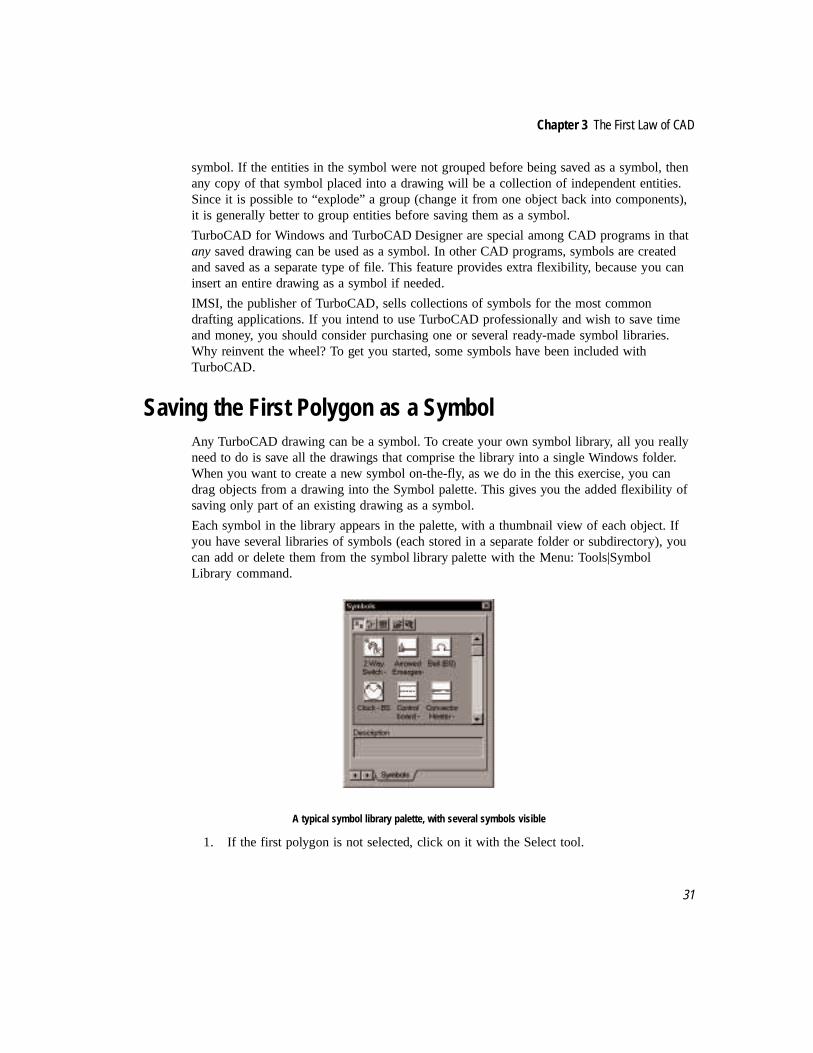
Each symbol in the library appears in the palette, with a thumbnail view of each object. Ifyou have several libraries of symbols (each stored in a separate folder or subdirectory), youcan add or delete them from the symbol library palette with the Menu: Tools|SymbolLibrary command.
A typical symbol library palette, with several symbols visible
1. If the first polygon is not selected, click on it with the Select tool.
The Complete Guide to TurboCAD for Windows V4
32
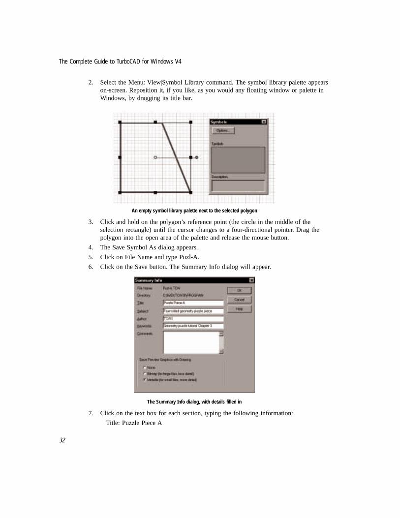
2. Select the Menu: View|Symbol Library command. The symbol library palette appearson-screen. Reposition it, if you like, as you would any floating window or palette inWindows, by dragging its title bar.
An empty symbol library palette next to the selected polygon
3. Click and hold on the polygon’s reference point (the circle in the middle of theselection rectangle) until the cursor changes to a four-directional pointer. Drag thepolygon into the open area of the palette and release the mouse button.
4. The Save Symbol As dialog appears.
5. Click on File Name and type Puzl-A.
6. Click on the Save button. The Summary Info dialog will appear.
The Summary Info dialog, with details filled in
7. Click on the text box for each section, typing the following information:
Title: Puzzle Piece A

Chapter 3 The First Law of CAD
33
Subject: Four-sided geometry puzzle pieceAuthor: (Your name)Keywords: Geometry puzzle tutorial Chapter 3Comments: Leave blank or fill in as you wish
8. Under Save Preview Graphics with Drawing, make sure Metafile is selected.
9. Click the OK button to save. The dialog disappears, and the symbol appears in thesymbol library palette.
Symbol library palette showing “Puzzle Piece A” symbol
TIP: When moving and rotating objects in TurboCAD, sometimes stray bits of color will stay onthe screen after an object moves. You can press function key <F5> at any time to refresh thescreen and remove these stray pixels. You may also click the redraw button on the Zoomtoolbar.
Creating the Second Puzzle PieceFollow the steps below to draw, group, and save the second puzzle piece as a symbol.
1. Click on the Single Line tool in the Insert Entity toolbar.
Single Line tool icon
2. Make sure the Grid tool is selected in the Snaps toolbar.
✔

The Complete Guide to TurboCAD for Windows V4
34
Grid Snap tool icon
3. In an open area of the drawing screen (move the symbol library pallet and/or use thescroll bars if necessary), click on a grid intersection and draw a line 3” straight down(-90 degrees in the Edit Bar).
First line of second puzzle piece is a 3" vertical line
4. Connecting to the bottom of the first line, draw a horizontal line 8” long.
5. Draw a third line that closes the polygon, creating a triangle.
Completed triangle next to first polygon
6. Click on the Select tool icon, and draw a selection window around the triangle.
7. Select Menu: Format|Create Group. The lines of the triangle are now one group.
8. Select the reference point, holding down the mouse button until the four-directionalpointer appears. Drag the triangle/group into the symbol library palette.
9. The Save Symbol As dialog appears.

Chapter 3 The First Law of CAD
35
Save Symbol As dialog
10. Type Puzl-B as the file name, and click on the save button.
11. The Summary Info dialog will appear.
Summary Info dialog for Puzzle Piece B

The Complete Guide to TurboCAD for Windows V4
36
12. Click on the text box for each section, typing the following information:
Title: Puzzle Piece B
Subject: Four-sided geometry puzzle
Author: (Your name)
Keywords: Geometry puzzle tutorial Chapter 3
Comments: Leave blank or fill in as you wish
13. Under Save Preview Graphics with Drawing, make sure Metafile is selected.
14. Click the OK button to save. The dialog disappears, and the symbol appears in thesymbol library palette. Press <F5> to refresh the screen if necessary.
Revised symbol library palette showing both puzzle pieces
Assembling the PuzzleThe pieces have been defined, now it is time to assemble the puzzle and look for thesolution to the mystery of the extra square inch. In the steps below, you will start by erasingthe objects now on screen, then place the symbols as needed to form the complete puzzle.
When a symbol is placed in a drawing, it appears highlighted with a selection rectangle. Thereference point is the symbol’s handle, and can be used to place the symbol accurately. Ifany snap command is active, the reference point will be the part of the symbol that snapsinto position. To simplify accurate placement, the reference point will be moved from thecenter to a corner on each piece. The corners will line up with the grid, allowing for a tight,accurate fit—and to make sure there’s no cheating!
Place the First Puzzle Piece
1. The Select tool should still be active. If not, click on the Select tool in the InsertEntity toolbar.
2. Draw a selection window around both puzzle pieces on the Paper. When selected,press the <Delete> key.

Chapter 3 The First Law of CAD
37
3. Drag and drop a copy of Puzzle Piece A (from the symbol library palette) into thedrawing.
4. Press the <Ctrl> key and move the selection cursor onto the reference point. Whenthe selection arrow changes to a hand holding a reference point, click the mousebutton to “pick up” the reference point.
5. Move the hand cursor to the upper left corner of the polygon, and click directly onthe corner. The reference point will move to this new location.
Before-and-after example of moving the reference point
6. Keep the cursor on the reference point, and it will change to the four-directionalpointer. Click to select the reference point, move the cursor to a point on a gridintersection in the top left portion of the screen and click again to place the referencepoint.
7. Click anywhere on the Paper to deselect the symbol. Press <F5> to refresh the screenif necessary.
Rotating a Selection
Next a second copy of Puzzle Piece A is placed in the drawing. This second copy needs tobe turned upside down before being placed next to the first piece. A rotation command willbe used in this example.
An object must be selected before it can be rotated. The selected object always rotatesaround the reference point. Results of a rotation command will vary depending on thelocation of the reference point. If the reference point is in the center of the object, the objectwill stay in the same relative location, but “spin” around the reference point. If the referencepoint is on a corner, the entire object will rotate on that corner, in effect moving the objectto a different location.
For a practical example of the importance of the reference point, place a pencil on a desk.Hold it in the middle with thumb and finger and turn it 90 degrees. Keep thumb and finger
reposition reference pointusing any snap mode
<Ctrl>-Click on reference point

The Complete Guide to TurboCAD for Windows V4
38
pressed against the desk as you turn the pencil. Notice how the center of the pencil stays inthe same location. Now hold one end of the pencil and again turn it 90 degrees. Be sure tokeep thumb and finger pressed against the desk. This time the pencil seems to jump to a newlocation.
TIP: Because rotation is always in relation to the reference point, some interesting effects arepossible. The reference point can be moved to a location away from the object, and thenrotated. For example, you could use the Snap to Arc Center command to locate a referencepoint at the center of a circle, then “orbit” the selection around that point.
✔ TIP: To restore the reference point to its original location, deselect and reselect the object.
Place and Rotate the Second Puzzle Piece
1. The Select tool should still be active. If not, click on the Select tool in the InsertEntity toolbar.
2. Drag and drop a copy of Puzzle Piece A (from the symbol library palette) into thedrawing, to the right of the first piece.
3. Highlight “0” in the Rotation field of the Edit Bar by pressing <Tab> twice. Type 180and press <Enter>.
Edit bar shows 180 degrees in the rotation field
4. Press the <Ctrl> key and move the selection cursor on to the reference point at thecenter of the symbol. When the cursor changes to the hand, click on the referencepoint.
5. Move the hand cursor to the upper left corner of the polygon, and click directly onthe corner. The reference point will move to this new location.
✔

Chapter 3 The First Law of CAD
39
The reference point has been moved to the upper left corner
6. Keep the cursor on the reference point, and it will change to the four-directionalpointer. Drag and drop the reference point onto the top right corner of the firstsymbol.
7. Click anywhere on the Paper to deselect the symbol. Press <F5> to refresh the screenif necessary.
Two copies of Puzzle Piece A placed side by side
Place the First Triangle
The first of two triangles (Puzzle Piece B) must now be placed into position. No rotation isrequired.
1. The Select tool should still be active. If not, click on the Select tool in the InsertEntity toolbar.
2. Drag and drop a copy of Puzzle Piece B (from the symbol library palette) into thedrawing, below the first two pieces.
3. Press the <Ctrl> key and move the selection cursor on to the reference point at the centerof the symbol. When the cursor changes to the hand, click on the reference point.
4. Move the hand cursor to the upper left corner of the symbol, and click directly on thecorner. The reference point will move to this new location.

The Complete Guide to TurboCAD for Windows V4
40
The reference point has been moved to the upper left corner of the triangle
5. Keep the cursor on the reference point, and it will change to the four-directionalpointer. Drag and drop the reference point onto the lower left corner of the firstsymbol pair.
6. Click anywhere on the Paper to deselect the symbol. Press <F5> to refresh the screenif necessary.
Three pieces of the square version of the puzzle are now in place
Complete the Square
One more triangle, and the square is completed. This fourth piece must be rotated 180degrees, using the same rotation technique as before.
1. The Select tool should still be active. If not, click on the Select tool in the InsertEntity toolbar.
2. Drag and drop a copy of Puzzle Piece B (from the symbol library palette) into thedrawing, to the right of the first three pieces.
3. Highlight “0” in the Rotation field of the Edit Bar. Type 180 and press <Enter>.
4. Press the <Ctrl> key and move the selection cursor on to the reference point at thecenter of the symbol. When the cursor changes to the hand, click on the referencepoint.

Chapter 3 The First Law of CAD
41
5. Move the hand cursor to the upper left corner of the triangle (which is also the upperleft corner of the selection rectangle), and click directly on the corner. The referencepoint will move to this new location.
Move the reference point to the upper left corner of the triangle
6. Keep the cursor on the reference point, and it will change to the four-directionalpointer. Drag and drop the reference point onto the same location used to place thefirst triangle—the lower left corner of the first symbol pair.
7. Click anywhere on the Paper to deselect the symbol. Press <F5> to refresh the screenif necessary. The square puzzle is completed.
The completed square puzzle
Assemble the Rectangle PuzzleNow comes the interesting part. When the four pieces are organized into a square, theycover 64 square inches. But when they are organized into a rectangle, they appear to cover65 square inches. If you don’t already know the reason behind this seemingly paradoxicalsituation, it will soon become visible.
If you took the time to create this puzzle from pieces of paper, you know that to form therectangle you have to turn over the two triangles in addition to rotating them. Since it isn’tpossible to pick up and turn over the triangles in our drawing, we need another technique.The hard way would be to draw another symbol. A slightly easier way would be to Mirror

The Complete Guide to TurboCAD for Windows V4
42
Copy the triangle (creating a mirror image), and erase the original. But the easiest way of allinvolves tricking TurboCAD into changing the scale of the triangle without changing thesize.
Positive and Negative Scale
Normally the X Scale and Y Scale fields in the Edit Bar are used to change the size of anobject. Scale values of less than one reduce the size of an object; scale values greater thanone increase the size. A scale of .5 reduces an object to one-half its original size; a scale of2 doubles the size of an object. To change the size of an object proportionally, both the Xand Y scales must be changed equally.
By selecting a scale of negative one (-1) for either the X or Y dimension, the scale commandcan flip an object, using either a horizontal (X) or vertical (Y) axis.
To visualize how flipping an object with the scale command works, go back to the pencil onthe desk. Lay the pencil horizontally. Hold the left end against the desk, and lift the rightend up and flip it over, keeping the left end in position. This is the equivalent of setting theX (horizontal) scale to -1. Changing the orientation from positive to negative points theobject in a reverse direction. Keeping the scale factor at 1 means the object maintains itsoriginal size.
To flip an object right to left, change the X scale to -1. To flip an object bottom to top,change the Y scale to -1. Both the X and Y scales can be changed to -1 if necessary.
Positive and Negative Rotation
The two copies of the four-sided polygon required to assemble the rectangle need to berotated, not flipped. In the exercise above, objects were rotated 180 degrees, one-half thedistance around a circle. It did not matter if the object rotated to the left or the right(counterclockwise or clockwise). But this time the required rotation is only 90 degrees, sothe direction of rotation becomes important.
By default, rotation in TurboCAD is counterclockwise. To rotate an object clockwise, type anegative value for the rotation.
TIP: In most CAD programs, positive numbers mean counterclockwise rotation, negativenumbers mean clockwise rotation, and that is that. But it is possible in TurboCAD to changethe positive direction of rotation, in effect swapping clockwise movement for counterclockwise.Use the Angle property of the Drawing Setup dialog (Menu: Tools|Angle) to make this change.
Place the First Section of the Rectangle Puzzle
1. Use the scroll bars and move the symbol library palette if necessary to gain room toassemble the rectangle puzzle below the square.
✔
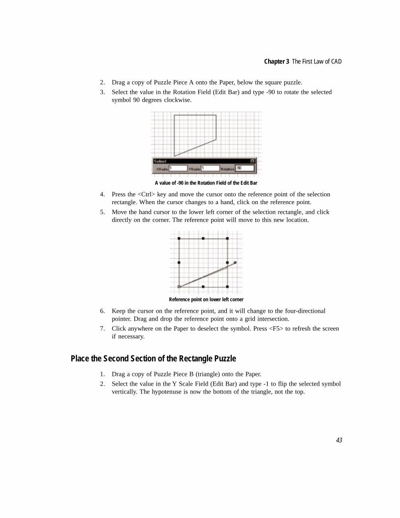
Chapter 3 The First Law of CAD
43
2. Drag a copy of Puzzle Piece A onto the Paper, below the square puzzle.
3. Select the value in the Rotation Field (Edit Bar) and type -90 to rotate the selectedsymbol 90 degrees clockwise.
A value of -90 in the Rotation Field of the Edit Bar
4. Press the <Ctrl> key and move the cursor onto the reference point of the selectionrectangle. When the cursor changes to a hand, click on the reference point.
5. Move the hand cursor to the lower left corner of the selection rectangle, and clickdirectly on the corner. The reference point will move to this new location.
Reference point on lower left corner
6. Keep the cursor on the reference point, and it will change to the four-directionalpointer. Drag and drop the reference point onto a grid intersection.
7. Click anywhere on the Paper to deselect the symbol. Press <F5> to refresh the screenif necessary.
Place the Second Section of the Rectangle Puzzle
1. Drag a copy of Puzzle Piece B (triangle) onto the Paper.
2. Select the value in the Y Scale Field (Edit Bar) and type -1 to flip the selected symbolvertically. The hypotenuse is now the bottom of the triangle, not the top.

The Complete Guide to TurboCAD for Windows V4
44
Using a value of -1 in the Y Scale field to flip the triangle
3. Press the <Ctrl> key and move the cursor onto the reference point of the selectionrectangle. When the cursor changes to a hand, click on the reference point.
4. Move the hand cursor to the upper left corner of the selection rectangle, and clickdirectly on the corner. The reference point will move to this new location.
Reference point on upper left corner of triangle
5. Keep the cursor on the reference point, and it will change to the four-directionalpointer. Drag and drop the reference point onto the upper right corner of thepreviously placed (Piece A) object.
6. Click anywhere on the Paper to deselect the symbol. Press <F5> to refresh the screenif necessary.
The first two pieces of the rectangle puzzle
Place Another Triangle
1. Drag a copy of Puzzle Piece B (triangle) onto the Paper, below the last two objectsplaced.
2. Select the value in the X Scale Field (Edit Bar) and type -1 to flip the selectedsymbol horizontally. The hypotenuse now faces to the upper left, not the upper right.

Chapter 3 The First Law of CAD
45
3. Press the <Ctrl> key and move the cursor onto the reference point of the selectionrectangle. When the cursor changes to a hand, click on the reference point.
4. Move the hand cursor to the lower left corner of the selection rectangle, and clickdirectly on the corner. The reference point will move to this new location.
Reference point on lower left corner
5. Keep the cursor on the reference point, and it will change to the four-directionalpointer. Drag and drop the reference point onto the lower left corner of the four-sidedpolygon.
Correct placement for the latest triangle: notice the gap starting to form
6. Click anywhere on the Paper to deselect the symbol. Press <F5> to refresh the screenif necessary.
Place the Final Section of the Rectangle Puzzle
1. Drag a copy of Puzzle Piece A (polygon) onto the Paper.
2. Select the value in the Rotation Field (Edit Bar) and type 90 <Enter> to rotate theselected symbol counterclockwise.

The Complete Guide to TurboCAD for Windows V4
46
Rotate the polygon 90 degrees
3. Press the <Ctrl> key and move the cursor onto the reference point of the selectionrectangle. When the cursor changes to a hand, click on the reference point.
4. Move the hand cursor to the upper right corner of the selection rectangle, and clickdirectly on the corner. The reference point will move to this new location.
Reference point on upper right corner of polygon
5. Keep the cursor on the reference point, and it will change to the four-directionalpointer. Drag and drop the reference point onto the upper right corner of the existinggroup of puzzle pieces. This will join the two corners at a grid intersection.
Correct placement for the final piece
6. Click anywhere on the Paper to deselect the symbol. Press <F5> to refresh the screenif necessary.

Chapter 3 The First Law of CAD
47
The SolutionCompare the square and the rectangle. Do you see the gap in the middle of the rectangle?You can measure that space, if you like. Use the multiline tool and Snap Vertex, and draw aline around the space. Use Local Menu|Close to finish. Then select the multiline andexecute Menu: View|Selection Info. The area will be equal to 1. Multiplying the sides of theobject to calculate square inches yielded 64 square inches for the square, because theadjoining sides of the objects meet at all points. But the same process yielded a product of65 square inches for the rectangle, because the adjoining sides do not meet at all points, andan extra square inch is “trapped” inside.
Doing this exercise on paper isn’t precise enough to notice the 1-square-inch gap. Using apaint-type program to sketch the problem would have been no better. But in CAD thesolution is obvious.
Moving OnWhile you may never need to draw this geometric puzzle again, the techniques andcommands used in this chapter are important ones. To review, this chapter covered:changing Paper scale and display; changing the on-screen view; window selection ofobjects; creating groups; creating and using symbols; rotating objects; flipping objects usingnegative scale references; and moving an object’s reference point.


4Keeping Design Simple
Draw, Trim, Mirror . . . Voila!
The adjective simple can be used in a derogatory sense, but most simple things hold greatpromise. Simple directions on how to drive to a friend’s house will ensure success. Simpletoys allow for greater imaginative input. Simple software products are more likely to beused than complex ones.
Simplicity in the realm of CAD means finding ways to create designs quickly and easily.The First Law of CAD (never draw the same thing twice), is a reflection of the need to keepthings simple. The project in this chapter is a simple design. The techniques used to create itare simple. You only need to draw three circles and six lines. The Trim and Mirrorcommands make quick work of completing the design as you leapfrog quickly from a fewlines to a complete project.
In this chapter you will draw a tape reel cartridge. There are three sections: the storagebarrel, the exposure plate, and the take-up reel. Both the storage barrel and the take-up reelhave gear teeth that fit over spindles. The storage barrel and the take-up reel are identical insize, giving the cartridge a symmetrical look.
Project for this chapter: tape cartridge

The Complete Guide to TurboCAD for Windows V4
50
The Design EnvironmentWhen starting a new project you need to start with two planning steps. The first is anevaluation of the design, to gain ideas on how to best draw your project. This evaluationleads to the second step, organizing TurboCAD to suit the requirements of the design.
TurboCAD offers a wide degree of flexibility in setting up the drawing environment. Bydrawing environment, we mean all the options and settings available in the program, as wellas the interface (how the program presents itself to the user).
In the last chapter, attention was given to the settings related to groups and Paper space.This was an example of organizing the CAD program based on the needs of the project. Inthis chapter the Paper will again be adjusted, including the grid. The display of distancesand coordinates will also be changed.
Most drawing environment settings are found in the Options menu, in one of two dialogs.Program Setup and Drawing Setup were both used previously, and will be used again in thischapter. The drawing environment is not to be confused with properties, which refers to thecharacteristics of objects (to be covered in detail in Chapter Nine). A related topic iscustomization of the desktop, covered in Chapter 13.
Start this project by adjusting the scale, the units, the grid, and the presentation of the Paper.
Adjust Drawing Settings
1. Launch TurboCAD and start a New drawing. Accept the Normal template.
2. Select Menu: Options|Units and Scale dialog.
3. Under “Units in Work Space” change Format to Fractional, make sure Show AllUnits is checked, and set Precision to 4.

Chapter 4 Keeping Design Simple
51
Grid and Advanced Grid dialogs, with settings as listed in the text
When fractions are used for coordinates and measurements, you must establish the level ofprecision. A Precision setting of 4 allows TurboCAD to identify distances as small as1/16". A Precision setting of 8 would allow the program to display distances and locationsdown to 1/256"; a Precision setting of 2 would only display distances in 1/2" increments.
4. Click on the Grid tab.
5. Highlight the value for X Spacing and type 1/8 in.
6. Highlight the value for Y Spacing and type 1/8 in.
7. Make sure Show Grid is checked.
8. Click the Advanced Grid tab.
9. Under “Frequency” set both X and Y to 1.
10. Under both “Minor X” and “Minor Y,” set Divisions to 8.
11. Click OK.
Spacing sets the distance between grid lines. Divisions sets how many minor grid spaces (notthe lines that define the spaces) appear between each major line. By setting Spacing at 1/8"and Divisions at 8, the distance between each minor grid line (the lighter lines) will be 1/8"and the distance between each major grid line (the heavier lines) will be 1". Frequencydetermines how visible grid lines alternate with invisible grid lines. If Spacing werestill 1/8" but frequency was 4, there would be invisible grid lines on the sheet. The GridSnap command will snap to any grid point, visible or not.

The Complete Guide to TurboCAD for Windows V4
52
Blue is the default color scheme of the grid. You can change the colors of both the major andminor grid lines using the Colors buttons in the Grid dialog. When you select either option, acolor wheel appears. The scroll bar to the right of the color wheel controls relative colorbrightness. To change a color, click the desired shade on the color wheel.
Major color wheel
12. Select Menu: Options|Program Setup. Click on the Desktop tab.
13. In the Paper Display box, make sure both Show Margins and Show Background arechecked.
14. Click OK.
Desktop dialog in Program Settings

Chapter 4 Keeping Design Simple
53
Draw Three CirclesEach side of the cartridge consists of three circles. These will be drawn using the grid andthe Coordinate Display as references, to make sure they are the right size.
TurboCAD offers seven ways to make a circle, each available from a button in the fly-outtoolbar. The Ellipse tools are also on this fly-out.
Circle/Ellipse fly-out toolbar
Here’s how each tool works:
Tool Action
Center and Point Specify a center point and a radius
Concentric Draw circles that share the same endpoint
Double Point Define two opposite points to establish the diameter
Tan to Arc Draw a circle tangent to an arc or another circle
Tan to Line Draw a circle tangent to a line
Triple Point Specify three points to establish the circumference
Tangent to 3 Arcs Draw a circle tangent to three existing arcs or circles
Ellipse Define a boundary rectangle to set width and height
Rotated Ellipse Draw an ellipse rotated at any angle
Fixed Ratio Ellipse Specify the ratio of the major axis length to the minor axis length
Center and Point
Concentric
Double Point
Tangent to Arc
Tangent to Line
Triple Point
Tangent to Three Arcs
Ellipse
Rotated Ellipse
Fixed Ratio Ellipse

The Complete Guide to TurboCAD for Windows V4
54
In this exercise only the Concentric circle tool will be used.
1. Select the Grid Snap tool and the Magnetic Point tool in the Snaps toolbar (left sideof screen).
Grid Snap (left) and Magnetic Point
2. Select the Zoom Window tool in the Views toolbar.
3. Drag a selection window around the top left quarter of the paper. The screen willredraw with a close-up view of this area.
Zoom Window (left) and Concentric Circle
4. To start the first circle, select the Concentric Circle tool (as shown above). Click onthe intersection of two major grid lines found at X 2" Y 6". Refer to the CoordinateDisplay at the bottom of the screen to help you find the right location.
5. Move the cursor up 1/4" (two grid lines) and click at X 2" Y 6 1/4" to finish theinnermost circle as illustrated below.
6. Move the cursor up 5/8", to X 2" Y 6 7/8". Click to place a second circle.
7. Move the cursor up 1/8" (to the next major grid line), and click at X 2" Y 7". Right-click and choose Finish.
Three circles placed using the on-screen grid and the Concentric Circle tool
Draw Gear Tooth
In the finished drawing there are five gear teeth on each side of the cartridge. Each tooth isidentical, so it is only necessary to draw one tooth; the others will be copied from theoriginal.

Chapter 4 Keeping Design Simple
55
The gear tooth will be drawn using a construction technique that takes advantage of the gridto simplify placement of the lines. A new snap, Middle Point, will also be used. WhenMiddle Point is active, the exact midpoint of a line can be identified for use (to start or end aline, place a copy, etc.)
A rectangle will be drawn, but only part of it will remain in the drawing. Rectangles andother polygons are considered to be singular objects in TurboCAD, not a collection ofindividual lines. To remove pieces of the rectangle, it will have to be “exploded” first, orchanged from a single entity to a collection of lines. The Menu: Format|Explode tool is usedfor this purpose. Parts of some lines will be trimmed off as excess before the tooth isfinished, using the Menu: Modify|Object Trim tool.
This technique is only one of several approaches that could be used in TurboCAD to createthe desired elements. We use this approach here so that you may experience the integrateduse of drawing and editing tools.
1. Use Zoom Window to get a close-up view of the innermost circle.
2. Select the Line tool from the Insert Entity toolbar (top of screen).
3. Click on the grid at X 1 7/8" Y 6 1/4" to start a line. This location is one minor gridline left of a major grid line.
4. Move the cursor one grid line down and right, and click at X 2" Y 6 1/8".
First line of gear tooth intersects inner circle
5. Start the second line at the end of the first line (X 2" Y 6 1/8").
6. Move the cursor up and right to X 2 1/8" Y 6 1/4" to finish the line.
Second line drawn

The Complete Guide to TurboCAD for Windows V4
56
7. Select Middle Point from the Snaps toolbar.
Middle Point Snap tool
8. Click and hold on the Line tool until the fly-out toolbar appears. Select the Rectangletool.
Rectangle tool
9. Click on the middle of the first line (the left line) at approximately X 1 15/16" Y 6 3/16".
10. Move the cursor down to the Coordinate Fields Display at the bottom of the screen(you can also press <Ctrl> <R>). Highlight the value in the X field. Type “2 1/16 in.”and press <Tab>.
11. The value in the Y field is now highlighted. Type “6 1/8 in.” and press <Enter>. Arectangle will be drawn.
The Coordinate Display shows the correct values for finishing the rectangle
Explode Rectangle
1. Click on the Select tool.
2. Click on the rectangle. A selection rectangle will appear.
3. Select the Menu: Format|Explode command.
4. Click anywhere on the Paper to deselect the rectangle.

Chapter 4 Keeping Design Simple
57
Trim and Delete Lines to Finish Tooth
This next section introduces the Object Trim command. It is used to cut off unwantedportions of lines or other objects. Object Trim cuts one object using an intersecting object asthe cutting edge; the command does not allow you to cut away a portion of a solitary object.To use the command, you first identify the cutting edge. This is the overlapping object thatwill not be changed. Then you identify the object to be trimmed, clicking on the part of theline (arc, etc.) that will be trimmed away.
You may want to glance back at the finished design to help you understand how lines will betrimmed and deleted to finish the gear tooth.
1. From the menu, select Modify|Object Trim.
2. The prompt at the bottom of the screen reads “Define the cutting edge.”
3. Click on the circle to identify it as the cutting edge. It will be highlighted.
4. The prompt reads “Add cutting edge (Shift) or select object to trim.”
5. Click on the left angled line, outside the circle, to trim it away
6. Click on the right angled line, outside the circle, to trim it away.
Before and after using Object Trim on the angled lines
7. Press <Esc> to deselect the circle as the cutting edge. The Object Trim command isstill active, but you must now select a new cutting edge.
8. Click on the left side of the rectangle to select it as the cutting edge.
9. Press <Shift> and click on the right side of the rectangle. Now both sides are selectedas cutting edges.
10. Click on the left angled line inside the rectangle.
11. Click on the right angled line inside the rectangle.
12. Click on the Select tool to end Object Trim.
13. Click on the top line of the rectangle. Press <Delete>.

The Complete Guide to TurboCAD for Windows V4
58
The lines inside the rectangle have been trimmed
Copy Tooth Around the Circle
The Fit Radial Copy tool will be used to make four new copies of the tooth, arrayed aroundthe inside of the small circle. It is one of eight copy commands in TurboCAD. The Mirrorcommand will be used later in this exercise; the others will be introduced later in the book.
Here’s how each copy tool works:
Tool Action
Linear Copy Copy objects along a line (real or imagined) by stating the intervalbetween each copy.
Radial Copy Copy objects along an arc (real or imagined) by stating the angularspacing between each copy and the rotation of each copy relative tothe previous copy.
Array Copy Copy objects in a two-dimensional pattern by stating the verticaland horizontal spacing between objects.
Fit Linear Copy Copy objects along a line by stating the total distance into which allthe copies will fit.
Fit Radial Copy Copy objects along an arc (real or imagined) by stating the totalangular distance in which all the copies must fit and the rotation ofeach copy relative to the previous copy.
Fit Array Copy Copy objects in a two-dimensional pattern by stating the dimensionof the rectangle into which they must fit.
Mirror Copy Create a mirror image of an object on the opposite side of a line thatyou specify.
Vector Copy Make a single copy of an object, specifying both the angle anddistance of the copy from the original
.
The difference between Radial Copy and Fit Radial Copy is that in Radial Copy you set thedistance (in degrees) between objects; in Fit Radial Copy you specify the total angulardistance (in degrees) for all objects, and TurboCAD will then determine the angular
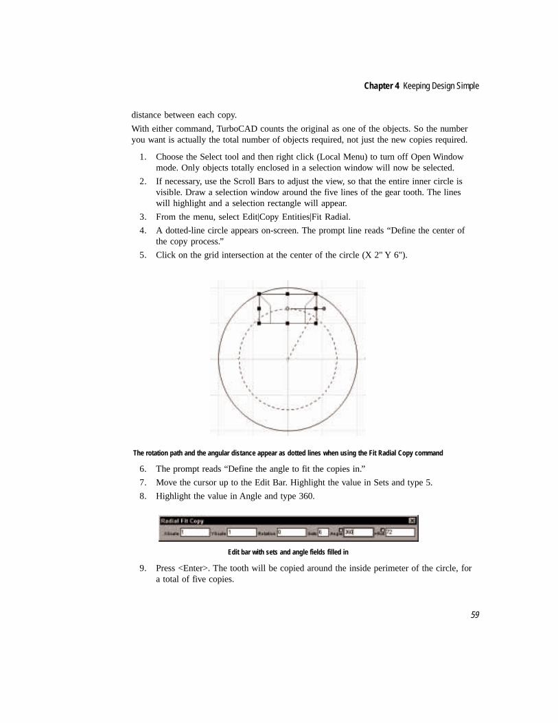
Chapter 4 Keeping Design Simple
59
distance between each copy.
With either command, TurboCAD counts the original as one of the objects. So the numberyou want is actually the total number of objects required, not just the new copies required.
1. Choose the Select tool and then right click (Local Menu) to turn off Open Windowmode. Only objects totally enclosed in a selection window will now be selected.
2. If necessary, use the Scroll Bars to adjust the view, so that the entire inner circle isvisible. Draw a selection window around the five lines of the gear tooth. The lineswill highlight and a selection rectangle will appear.
3. From the menu, select Edit|Copy Entities|Fit Radial.
4. A dotted-line circle appears on-screen. The prompt line reads “Define the center ofthe copy process.”
5. Click on the grid intersection at the center of the circle (X 2" Y 6").
The rotation path and the angular distance appear as dotted lines when using the Fit Radial Copy command
6. The prompt reads “Define the angle to fit the copies in.”
7. Move the cursor up to the Edit Bar. Highlight the value in Sets and type 5.
8. Highlight the value in Angle and type 360.
Edit bar with sets and angle fields filled in
9. Press <Enter>. The tooth will be copied around the inside perimeter of the circle, fora total of five copies.

The Complete Guide to TurboCAD for Windows V4
60
10. Click on the Select tool to end Fit Radial Copy.
New copies of the gear tooth have been placed around the circle using Fit Radial Copy
Draw the Exposure Plate
Two parallel lines extending from the top of the outer circles represent the exposure plate.The Double Line tool will be used to draw the lines, then the Object Trim command willgraft the lines into the take-up reel.
Double Line is actually one of eight tools that can draw parallel lines as a single entity. Theeight tools are:
Tool Action
Double Line Segment Define two endpoints to draw a double line
Double Line Multiline Draw a series of connected double lines
Double Line Polygon Draw a double line polygon by providing the number of sides in thepolygon and the distance from the center to one corner.
Dbl. Line Irregular Polygon Draw a double line irregular polygon a side at a time.
Double Line Rectangle Draw a horizontal double line rectangle.
Dbl. Line Rotated Rectangle Draw a double line rotated rectangle to any angle.
Perpendicular Double Line Draw a double line perpendicular to an existing line.
Parallel Double Line Draw a double line parallel to an existing line.
Double lines have special properties, or characteristics, that you must choose before use. Adouble line dialog is available by right-clicking on a double line tool icon, or by selectingMenu: Format|Properties.
In the Double Line dialog you can:
• Set the distance between the two lines.
• Decide if the endpoints of the double line are to be open or closed (capped). Each

Chapter 4 Keeping Design Simple
61
endpoint can be set individually.
• Set the alignment of the double line. The options are left, right or center. If youchoose left align, for example, the points you click on to identify the double line willbecome the left side. If you wanted a double line to straddle a series of points, youwould choose Center Alignment.
To determine which is the left and which is the right side of a double line, imagine yourselfstanding on the starting point of the line, facing the endpoint. No matter which way yourotate the line, the right side remains on your right. This is similar to the terms “port” and“starboard” which define directions relative to the fore and aft of a ship. The critical thing isto know the direction in which the double line is drawn.
In the next sequence you will graft a double line to the outer circle. You will set theproperties “on the fly” using the Local Menu (right click of the mouse on the double linetool). It is not necessary to explode the double line before using Object Trim to connect theline to the circle.
1. Click on Zoom Full View in the View toolbar.
Zoom full view
2. Click on Zoom Window in the View toolbar. Starting at the margin border in theupper left corner of the Paper, drag a selection window around the drawing that is sixmajor grid squares wide and three major grid squares deep.
3. Click on Double Line in the Insert Entity toolbar.
Double line tool
4. Right-click on the Double Line tool to summon the Properties dialog. Click on theDouble Line tab.
5. Highlight the value in the Separation field and type “1/8 in.”
6. In the Reference section, click on the radio button for Left.
7. Click on OK.
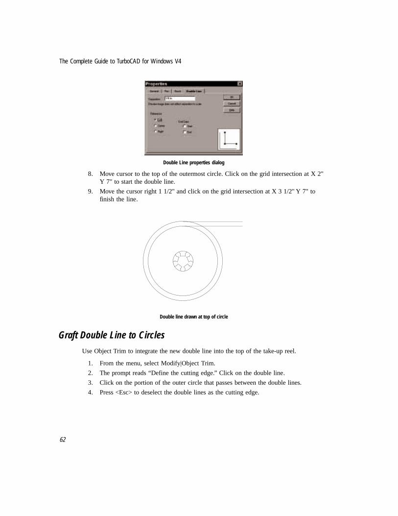
The Complete Guide to TurboCAD for Windows V4
62
Double Line properties dialog
8. Move cursor to the top of the outermost circle. Click on the grid intersection at X 2"Y 7" to start the double line.
9. Move the cursor right 1 1/2" and click on the grid intersection at X 3 1/2" Y 7" tofinish the line.
Double line drawn at top of circle
Graft Double Line to Circles
Use Object Trim to integrate the new double line into the top of the take-up reel.
1. From the menu, select Modify|Object Trim.
2. The prompt reads “Define the cutting edge.” Click on the double line.
3. Click on the portion of the outer circle that passes between the double lines.
4. Press <Esc> to deselect the double lines as the cutting edge.

Chapter 4 Keeping Design Simple
63
The portion of the outer circle in between the two double lines has been trimmed away
5. Object Trim is still active, awaiting selection of a new cutting edge. Click on theouter circle to select it as the cutting edge.
6. Click on the bottom double line inside the outer circle.
7. Click on the Select tool to end Object Trim.
Trimming of double line and circles is completed
Mirror Copy to Finish Cartridge
One last step remains; to complete the object by creating a mirror image copy of theexisting objects. Use the Mirror Copy tool whenever you need to create a mirror image of anobject. The copy is placed using a line that you identify. If the line is a distance from theoriginal, the copy will be the same distance away from the line on the opposite side.
Before you can mirror copy you will have to explode the double lines. If not, when you useMirror Copy the new double lines will be mirrored both vertically and horizontally, givingan effect of flipping the double lines above the circle. (This happens because the double lineis recorded as having a “left-to-right” orientation, which remains true after the MirrorCopy.) Try the sequence below without exploding first, if you like, to see this for yourself.Use the Undo tool to undo the wrong effect, and then explode the double lines before usingMirror Copy again.
1. Click on the double lines with the Select tool.
2. Select Menu: Format|Explode. The double lines are now two individual lines.
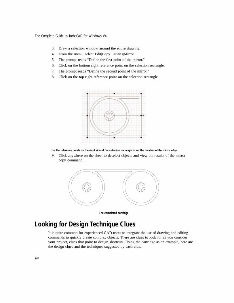
The Complete Guide to TurboCAD for Windows V4
64
3. Draw a selection window around the entire drawing.
4. From the menu, select Edit|Copy Entities|Mirror.
5. The prompt reads “Define the first point of the mirror.”
6. Click on the bottom right reference point on the selection rectangle.
7. The prompt reads “Define the second point of the mirror.”
8. Click on the top right reference point on the selection rectangle.
Use the reference points on the right side of the selection rectangle to set the location of the mirror edge
9. Click anywhere on the sheet to deselect objects and view the results of the mirrorcopy command.
The completed cartridge
Looking for Design Technique CluesIt is quite common for experienced CAD users to integrate the use of drawing and editingcommands to quickly create complex objects. There are clues to look for as you consideryour project, clues that point to design shortcuts. Using the cartridge as an example, here arethe design clues and the techniques suggested by each clue.

Chapter 4 Keeping Design Simple
65
• The width of the tape path between reels, the width of the outer portion of each reeland the distance between the outer portion and the inner wheels are proportional. Thegrid spacing was set to match these proportions.
• The circles on each take-up reel have a common center, which means they areconcentric. The use of the Concentric Center tool saved many keystrokes and mouseclicks when compared to the other circle tools.
• Drawing the first tooth at the top of the circle, centered on the (imagined) top-to-bottom diameter line, made it easier to visualize the symmetrical nature of eachtooth.
• The combination of single lines, a rectangle, and Object Trim to draw the first toothwas one option; using Single Line Multiline was another. The line/rectangle/trimsequence required less step-by-step planning, because the intersection of the twosingle lines defined the bottom midpoint of the rectangle. In a reversal of an oldcliche, in this situation function followed form.
• Once the first tooth was drawn correctly, Fit Radial Copy became the best tool for notonly drawing the rest of the teeth, but for drawing the correct spacing between teethwithout elaborate calculations. You could use Fit Radial Copy and the Undo tool totest various patterns, in effect using TurboCAD for initial design as well as drafting.
• The symmetrical nature of the completed cartridge suggests the use of Mirror Copy tosave steps. An alternative method would have been to save the left side as a block,and then place the block using the flipping technique described in Chapter Three. Butblocks are best used when there will be repeated placements of an object; in thisdrawing you would have only placed the block once. Plus, correctly placing theflipped block would be more complicated than using Mirror Copy on the original.
• Double Line was used to draw the exposure plate because of the way the bottom lineintersected the outer circle (before it was trimmed). Trimming is the generally theeasiest way to precisely connect a line to a circle when the line is not tangent orperpendicular. If Single Lines were used to draw the exposure plate, it would be beenmore complicated to draw the bottom line without using the Trim command.
Practice Makes PerfectTry to practice the techniques presented in this chapter until they become routine. ObjectTrim, Explode, and the various copy commands are the most common non-drawing toolsused in a CAD program. As you gain familiarity with them, they will become simple to use,and their usefulness will become obvious in a variety of situations.

The Complete Guide to TurboCAD for Windows V4
66

5The Designer View
The Power of Visual Feedback
Imagine yourself at a football game in a very large stadium. You have mid-field tickets,about 40 rows up. Good seats, great view, right? Now imagine there are no yard lines, noboundary lines anywhere on the field. From goal to goal, the field is solid green.
Kickoff time comes—where does the referee place the ball? If the kick goes into the endzone and is not returned, where is the 20-yard line? How will you know if a receiver runsout of bounds? If play is near the end zone, how can you tell if the ball is placed on the one-yard line or the four-yard line? Will the referees have to drag a measuring tape out for everyplay? Where would they measure from?
Fortunately, this is an imaginary game. Every real football stadium has yard markers andboundary lines on the field. These elements provide context known as visual feedback.Players, officials and fans can see what’s going on, they can see where it happens, and theydon’t have to constantly measure and compute distances. As the game progresses up anddown the field, a quick glance is enough to analyze and interpret all elements of the gamerelated to field position.
TurboCAD provides visual feedback, too. You have already been introduced to threemethods of visual feedback: the screen grid, the Paper, and the Coordinate Display. Whenthe screen grid is active, you have an immediate sense of the size of objects. Using the gridas a guide, drawing objects on the screen is easier and more intuitive. Combine the visualfeedback of an on-screen grid with the accuracy offered by Grid Snap, and you already havea drafting tool more useful than pencils and graph paper.
The grid and Grid Snap are only the beginning. TurboCAD provides visual feedback inother ways. This chapter will explore the various aspects of visual feedback in TurboCADand how it relates to all other parts of the program. Concepts, tools and commands to becovered in this chapter include:
• Rubberbanding
• Snaps
• Magnetic Point

The Complete Guide to TurboCAD for Windows V4
68
• Aperture
• Ortho
• The coordinate plane
• Absolute, Relative, and Polar coordinates
• Origin Point and Relocate Origin
• Zoom and Redraw
The screen elements common to all Windows programs are also part of visual feedback inTurboCAD. For help with such elements as scroll bars, menus, toolbars, selection arrows,etc., refer to your Windows documentation.
The features discussed in this chapter are found in the Modes menu and the View menu.This is the first of two chapters to cover visual feedback. More advanced features arediscussed in Chapter 13.
RubberbandingOne of the most helpful visual feedback elements is called Rubberbanding. When you startto draw a line or any other geometric object, after you place the start of the object, the line(or circle, etc.) sticks to the cursor until you click to finish drawing the object. The ability tosee a line or other object extend from the cursor makes it easier to see how the object will fitinto the drawing. It may seem like a simple thing, but the lack of it would make drawing inTurboCAD much less intuitive.
SnapsSnaps were briefly defined in Chapter Two, and have been mentioned several times since. Adetailed discussion is now appropriate. Snap modes let you connect to exactly the kind oflocation you need. If you need to connect to the end (vertex) of a line, use Snap Vertex. Ifyou need to connect to the midpoint of a line, use Snap Midpoint.
It is important to use snaps whenever possible for two reasons. The first is accuracy. Usingsnaps to connect lines and other objects allows you to take full advantage of the accuracyavailable in TurboCAD. Some new users, not realizing the importance of snaps, try to drawby "just coming close" when connecting lines. When they use dimensioning tools, they aresurprised to find that objects in the drawing are not the exact sizes they should be.
The second reason to use snaps whenever possible is for efficiency. Snaps help you locatethe point you need quickly. Consider the difference between finding the midpoint of a lineby using Snap Midpoint, or by using a drafting construction technique. Using the snap, youimmediately connect to the exact midpoint. Using the construction method, you must drawextra lines to find the exact same point.
You can define snap points that relate to objects, construction lines (covered in Chapter Six),and the grid. All snap mode functions are similar: You first set the snap mode, then click on

69
Chapter 5 The Designer View
or near the object that you want to snap to. Rather than placing the object exactly where youclicked the mouse, TurboCAD will place the object according to the snap mode in use. Theexact location chosen depends on the snap mode in use. You can, for example, snap to theend of a line, the midpoint of a line, the center of a circle, or a point on the grid.
Here is a list of snaps and their functions in TurboCAD:
Tool Action
No Snap Connection is made to the exact location of the mouse click. NoSnap turns off any active snaps.
Snap to Vertex Connect to the nearest end of a line segment, endpoint of an arc, orcorner of a polygon, multiline or text element.
Snap to Nearest On Graphic Connect to the nearest point on any entity.
Snap to Midpoint Connect to the midpoint of a line segment.
Snap to Arc Center Connect to the center of an arc or circle.
Snap to Quadrant Point Connect to the nearest quadrant point (at 0, 90, 180, or 270 degrees)on the circumference of a circle or arc.
Snap to Intersection Connect to the nearest intersection of two line segments.
Snap to Grid Connect to the nearest grid point or intersection of grid lines.
Snaps and the Local Menu
You can change snap modes in four different ways. You can use the menu, the Snap toolbar,the local menu, or with Single Entry Keyboard Equivalents (SEKEs). SEKEs are discussedin Chapter 14. The local menu is available at any time while using TurboCAD by clickingthe right mouse button. The local menu is context-sensitive: The specific commands andoptions available in the local menu change with the current activity. The concept of localmenu is to provide you with suggestions of possible commands appropriate to the currentactivity. Not taking advantage of the local menu is like struggling to lift a heavy rock whena champion weight lifter has offered to do it for you. Timing is everything, and theprogrammers of TurboCAD have done a good job of choosing what commands and toolsshould be in the local menu at any given time.
When you choose a snap from the menu or the Snap toolbar, the effect is the same: The snapmode remains active until you reset it. The local menu is different. Use it for “one shot”mode changes, or local snaps. This means that when you change snap modes in the localmenu, the snap you choose remains in effect only until you define the next point (finishdrawing the object, etc.). TurboCAD then switches back to the last mode you set in themain menu or toolbar, or defaults to No Snap mode.
Local snap is useful because it lets you set the snap mode you use most frequently in the

The Complete Guide to TurboCAD for Windows V4
70
main menu or toolbar, then switch modes “on the fly” in the local menu as you draw. Manyusers like to set Grid Snap as their default snap mode, for example. But the need may ariseto snap to a corner of a polygon not located on the grid. To do this, change the snap modetemporarily to Vertex (endpoint) in the local menu and define the point on the polygoncorner. TurboCAD then automatically switches back to Grid Snap.
Combining Snap Modes
Some snap modes can be combined with one another, and some are mutually exclusive.No Snap turns off all other snap modes. Snap Nearest on Graphic (which snaps to thenearest point on any object) also turns off all other snap modes. Magnetic Point, definedlater in this chapter (and used in the previous chapter), stays on no matter which snap modesare active.
The remaining snap modes all connect to a particular node (nodes are key points that definethe object geometrically), and they are not mutually exclusive. For example, Snap to Gridand Snap Vertex can both be active at the same time. If both are on, and you click the mousewhile a grid point and a line segment are both very close, the point will snap to either anendpoint of the line segment or to the grid point, whichever is closest to the mouse cursor.For a more detailed discussion of this kind of situation, see Aperture later in this chapter.
The snap modes that can be used at the same time are all in the same section of theModes|Snaps submenu, and are displayed together in the Snaps toolbar. The No Snap toolwill not turn off Ortho Mode (defined later in this chapter). Exercises throughout the rest ofthis book will introduce the various snaps not already used.
Magnetic PointMagnetic Point visually identifies the location of snap points. The feature can be turned onor off. The menu location is Modes|Snaps|Show Magnetic Point. A check mark appears inthe menu by the title when the feature is active. Its icon is located in the Snaps toolbar (leftside of the screen).
Magnetic Point tool icon
When this Magnetic Point is active, as you move the mouse cursor within a critical distancefrom the snap point, the rubberband line will be attracted to the snap point, previewing itsexact location. In other words, Magnetic Point scouts ahead to find potential connectionsthat match the snap commands you have chosen. Unless you are using a slow computer, orunless you are working on a very large drawing, it is probably useful to have this mode onall the time.

71
Chapter 5 The Designer View
Rubber band attracted to a snap point
ApertureThe phrase “a critical distance” was used in the last paragraph to describe how MagneticPoint assesses potential snaps. This critical distance between the point of the mouse clickand the snap point is called the snap aperture. You can think of the snap aperture as a circlecentered around the point of the mouse cursor. If a qualifying snap point is located withinthe snap aperture at the time of the mouse click, your action will connect to that snap point.If more than one object is located within the snap aperture, the connection will be made tothe closest snap point.
To display the snap aperture, select Menu: View|Aperture. The aperture appears as a circlearound the cursor. The radius of the snap aperture is controlled in the General property sheetof the Menu: Tools|Program Setup dialog.
✔ TIP: If you use the Coordinate Fields to define a point, you override any active snap.
Ortho ModeThe word orthogonal comes from the Greek: “ortho-” means straight and true; “-gon” refersto object and angles. (Now if anyone ever says to you “CAD is all Greek to me” you canexplain why.) Ortho mode in TurboCAD (Menu: Modes|Snaps|Ortho) limits the movementof the cursor if it is showing rubberband action as you create an object. By default, OrthoMode will limit the angle of the rubberband to be parallel to either the X or Y axis. Anotherway to define this effect would be to say that an object can only be drawn to either truehorizontal (a heading of either 90 or 270 degrees on the coordinate plane) or true vertical (aheading of either 0 or 180 degrees on the coordinate plane).
snap point
location of mousecursor

The Complete Guide to TurboCAD for Windows V4
72
Drawing a line with Ortho mode active
Ortho mode can be modified to change both the specific headings (the direction a linepoints) and the number of degrees between headings. For example, you could force lines tobe drawn at 30-degree increments starting at a heading of 10 degrees. The menu item tochange the default Ortho setting is Menu: Tools|Drawing Setup|Angle.
The <Shift> key acts as a clutch to temporarily engage or disengage Ortho mode. If Orthomode is on, and you need it off temporarily, use the <Shift> key to shut it off for themoment. Or, if Ortho mode is off, and you want it to help you draw just one line, press the<Shift> key as you draw the line.
The Coordinate PlaneThe nature of the coordinate plane was introduced in Chapter One, but not explained indepth. The coordinate plane, and the various ways of using it, are fundamental to any CADprogram. The objects you draw are stored in the drawing file by their location on thecoordinate plane. TurboCAD offers three coordinate system modes: Absolute, Relative, andPolar. Absolute and Relative are based on the Cartesian coordinate system; Polar isconsidered as its own coordinate system.
Cartesian CoordinatesThe Cartesian coordinate system starts with an origin point, through which two axes pass.The horizontal axis is X, the vertical axis is Y. You can name the location of any point on thecoordinate plane by describing its distance along each axis from the origin. For example, tostate the location of a point that is 2 units measured horizontally from the Y axis and 3 unitsmeasured vertically from the X axis, you would use the coordinates (2,3). For locations tothe left of the Y axis or below the X axis you need to use negative values. To specify alocation 2 units to the left of the Y axis and 2 units below the X axis, you would use thecoordinates (-2,-2).
clickhere
to define a point here

73
Chapter 5 The Designer View
(-2,-2)
(2,3)
Points defined in Cartesian coordinates
Absolute CoordinatesThe phrase absolute coordinates means you are defining the location of points on thecoordinate plain relative to the origin point (0,0). The origin point never changes locationunless you redefine it using the Page Setup dialog. By default, the origin is in the lower leftcorner of the page.
Relative CoordinatesSometimes it is more important to know how far the cursor is from the last point placed thanto know how far the cursor is from the origin point. The coordinate display can be adjustedto show that distance. This is known as relative coordinates. It means you are defining thelocation of points on the coordinate plain relative to the last point placed. If you are drawingwith the Multiline tool, for example, every time you click to set another line, that particularendpoint becomes the new (0,0) location.
If the cursor is at (0,0), Absolute Coordinate Mode is active, and you move the cursor 1” upand 1” right, the coordinate display will show X 1” Y 1”. If you start a line at this locationand then move the cursor 1” up and 1” right again, the coordinate display will read X 2” Y2”. But consider the same actions if Relative Coordinate Mode is active. The cursor starts at(0,0) and moves X 1” Y 1”. The relative coordinate display reads X 1” Y 1”. But as soon asyou click the mouse to define that point as the start of a line, the coordinate display revertsback to showing X 0, Y 0. Move the cursor another X 1” Y 1”, and the coordinate displayagain reads X 1” Y 1”, even though that’s what it said a second ago. The difference is thatyou are now measuring the location of the cursor by its distance from the last point placed,rather than the origin point.
Another name used for relative coordinates in some CAD programs is Delta Coordinates,because the delta symbol (D) is the symbol for change in mathematics. When TurboCAD isdisplaying Relative coordinates, the plus-or-minus character ( ± ) precedes the X or Y in thecoordinate display, and the last point placed on the drawing is highlighted with a small solidred square.
An easy way to remember the difference between absolute and relative coordinate is to use
+ 2,2
-2,-2 +
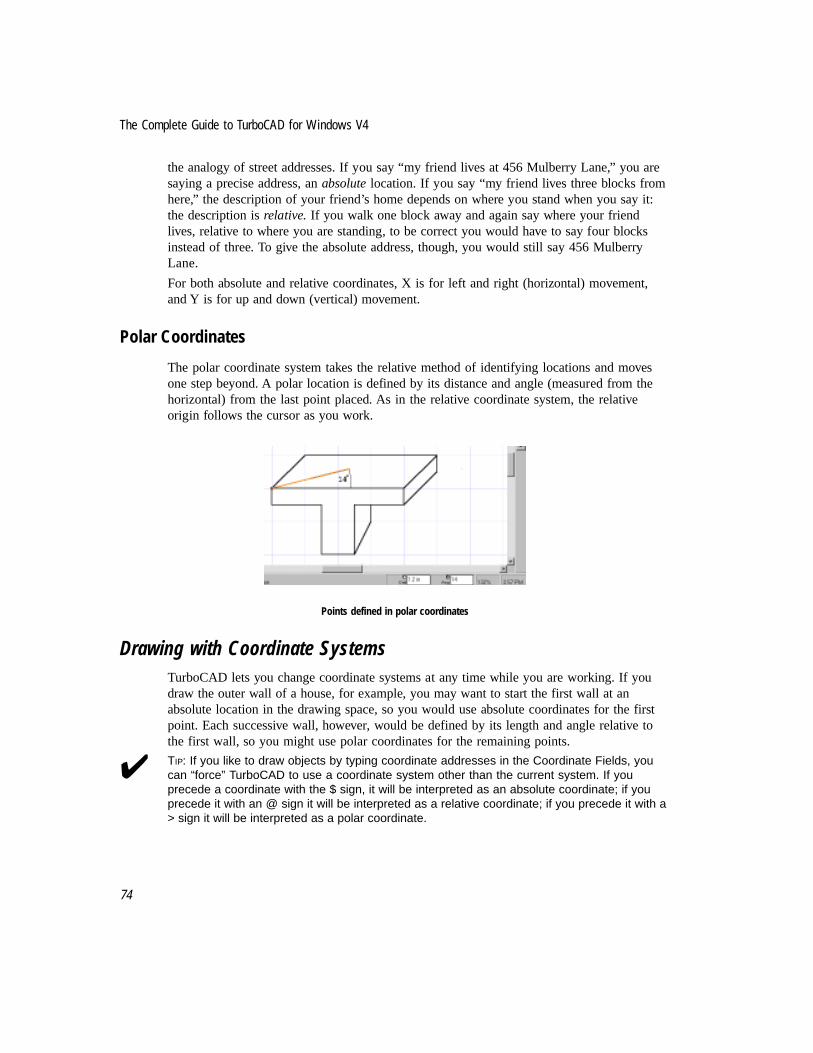
The Complete Guide to TurboCAD for Windows V4
74
the analogy of street addresses. If you say “my friend lives at 456 Mulberry Lane,” you aresaying a precise address, an absolute location. If you say “my friend lives three blocks fromhere,” the description of your friend’s home depends on where you stand when you say it:the description is relative. If you walk one block away and again say where your friendlives, relative to where you are standing, to be correct you would have to say four blocksinstead of three. To give the absolute address, though, you would still say 456 MulberryLane.
For both absolute and relative coordinates, X is for left and right (horizontal) movement,and Y is for up and down (vertical) movement.
Polar Coordinates
The polar coordinate system takes the relative method of identifying locations and movesone step beyond. A polar location is defined by its distance and angle (measured from thehorizontal) from the last point placed. As in the relative coordinate system, the relativeorigin follows the cursor as you work.
Points defined in polar coordinates
Drawing with Coordinate SystemsTurboCAD lets you change coordinate systems at any time while you are working. If youdraw the outer wall of a house, for example, you may want to start the first wall at anabsolute location in the drawing space, so you would use absolute coordinates for the firstpoint. Each successive wall, however, would be defined by its length and angle relative tothe first wall, so you might use polar coordinates for the remaining points.
✔ TIP: If you like to draw objects by typing coordinate addresses in the Coordinate Fields, youcan “force” TurboCAD to use a coordinate system other than the current system. If youprecede a coordinate with the $ sign, it will be interpreted as an absolute coordinate; if youprecede it with an @ sign it will be interpreted as a relative coordinate; if you precede it with a> sign it will be interpreted as a polar coordinate.

75
Chapter 5 The Designer View
Views of the Drawing SpaceThe TurboCAD drawing space is a plane on which you draw or place lines and otherobjects. A view is the area of the drawing space that appears on your screen. As yourdrawing becomes larger and more complex, it is important to be able to find views that letyou work at the right location in the drawing, at an appropriate level of detail.
TurboCAD offers a variety of options for adjusting the view, known as panning (moving theview but not changing the resolution) and zooming (changing the resolution).
✔ TIP: Other powerful ways to control your view of the drawing include selectively viewing layers,(covered in Chapter Nine), Aerial View (Chapter 14), and Viewports (Chapter 14).
ZoomingZooming means to move in or out of the drawing space, viewing the drawing at a greater orlesser level of detail. The Zoom Window command was used in the last chapter; it is one ofseveral zoom commands found in the menu at View|Zooms, or on the Zoom toolbar:
Command Action
Zoom In Move one step into the drawing.
Zoom Out Move one step further from the drawing,
Zoom Window Select a specific area to view.
View Extents Zoom to a view that contains all of the objects in the drawing.
Full View Display the full sheet.
Printed Size View the drawing at the size it will be when printed.
An additional zoom command, Previous View, is not in the Zooms submenu, but is found atMenu: View|Previous View. This command is especially handy for switching back and forthbetween two views.
One quick and easy way to zoom is to use the plus and minus keys of the numeric keypad:plus zooms in one step; minus zooms out one step. The amount of each step depends on thezoom factor, which by default is 2. With the zoom factor at 2, Zoom In cuts the view in half,Zoom Out doubles the view. The zoom factor can be changed in the Menu:Options|Program Setup dialog.

The Complete Guide to TurboCAD for Windows V4
76
Zooming in on a view
When you zoom in and out using the plus and minus keys, the view centers on the mousecursor. If you zoom in using a menu or toolbar command you will zoom in on the center ofthe current view, regardless of cursor location. As you zoom out, TurboCAD simplifiessmall objects to increase redraw speed.
✔ TIP: To zoom in on a particular point in the drawing and place it at the center of the screen,place the mouse cursor over the point and press the <+> key on the numeric keypad.
PanningPanning means to move the view to another location across the drawing. TurboCADprovides two menu commands for panning, plus the scroll bars and the use of the arrowkeys.
The scroll bars work the same way they do in other Windows programs. You can click thescrollbar arrow buttons to scroll one step, click in the body of the scrollbar to scroll aboutone-third of a screen, or drag the “thumb” of the scrollbar to move quickly across thedrawing. The arrow keys are also simple and intuitive: press the up, down, left, or rightarrow key to pan a single step.
✔ TIP: To quickly pan to a specific point, place the mouse cursor at the point, then type <Ctrl> +<End>. The screen will instantly move to a view with the point you chose at the center of thescreen.
The Pan commands are found in the View menu:
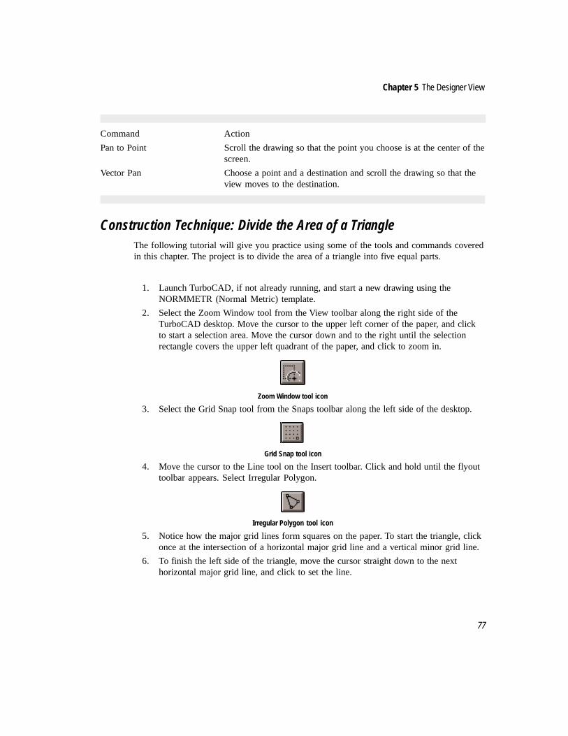
77
Chapter 5 The Designer View
Command Action
Pan to Point Scroll the drawing so that the point you choose is at the center of thescreen.
Vector Pan Choose a point and a destination and scroll the drawing so that theview moves to the destination.
Construction Technique: Divide the Area of a TriangleThe following tutorial will give you practice using some of the tools and commands coveredin this chapter. The project is to divide the area of a triangle into five equal parts.
1. Launch TurboCAD, if not already running, and start a new drawing using theNORMMETR (Normal Metric) template.
2. Select the Zoom Window tool from the View toolbar along the right side of theTurboCAD desktop. Move the cursor to the upper left corner of the paper, and clickto start a selection area. Move the cursor down and to the right until the selectionrectangle covers the upper left quadrant of the paper, and click to zoom in.
Zoom Window tool icon
3. Select the Grid Snap tool from the Snaps toolbar along the left side of the desktop.
Grid Snap tool icon
4. Move the cursor to the Line tool on the Insert toolbar. Click and hold until the flyouttoolbar appears. Select Irregular Polygon.
Irregular Polygon tool icon
5. Notice how the major grid lines form squares on the paper. To start the triangle, clickonce at the intersection of a horizontal major grid line and a vertical minor grid line.
6. To finish the left side of the triangle, move the cursor straight down to the nexthorizontal major grid line, and click to set the line.

The Complete Guide to TurboCAD for Windows V4
78
7. To draw the bottom line of the triangle, move the cursor three grid spaces to the rightand one grid space up, and click to set the line.
8. To complete the triangle, right-click and select Finish from the local menu.
Triangle created using Irregular Polygon
9. Move the cursor into the center of the triangle. Press the plus key on the numerickeypad to get a close-up view of the triangle.
10. Select the Double Point Circle tool from the circle flyout toolbar.
Double Point tool icon
11. Click on each end of the first line (left line) of the triangle to draw a circle using theline as the diameter of the circle.
Add a circle to the triangle
12. Select the Single Line tool from the Line flyout toolbar.

79
Chapter 5 The Designer View
Single Line tool icon
Next, using the horizontal minor grid lines as a guide, draw four lines perpendicular to theleft side of the triangle.
13. To draw the first line, click on the line one grid intersection below the top. Move thecursor left so that the line will intersect the circle, and click on a grid point to end theline.
14. Repeat the process three times at the other intermediate grid points along the left sideof the triangle. These lines divide the left side of the triangle into five equal parts.
Draw four perpendicular lines that intersect the circle on the left
15. Select the Concentric Arc tool from the Arc flyout toolbar of the Insert Entity toolbar.
Concentric Arc tool icon
16. Select the Snap Intersection and Magnetic Point tools from the Snaps toolbar (alongthe left side of the TurboCAD desktop).
Snap Intersection (left) and Magnetic Point tool icons
Next draw a series of arcs intersecting the left side of the triangle. Each arc will start at theintersection of the dividing lines and use the top corner of the triangle as the center.
17. For the first arc, start by clicking at the top corner of the triangle, to set the center ofthe arc.
18. Click on the intersection of the top dividing line and the circle, to set the radius.

The Complete Guide to TurboCAD for Windows V4
80
19. Click again at this same location to set the start of the arc.
20. Move the cursor to the right and click on a grid point that allows the arc to passthrough the left side of the triangle.
21. The Concentric tool remains active, and has identified the center of the first arc foruse again.
22. Move the cursor to the intersection of the second dividing line and the circle, andclick to set the radius.
23. Click again at this same location to set the start of the arc. Move the cursor to theright and click on a grid point that allows the arc to pass through the left side of thetriangle.
24. Repeat the steps above to draw two more arcs, to match the illustration.
Draw concentric arcs that intersect the left side of the triangle
25. Select the Parallel Line tool from the Single Line flyout toolbar of the Insert Entitytoolbar.
Parallel Line tool icon
26. The Parallel Line tool draws a straight line parallel to a line you select. Click on thebottom line of the rectangle. To draw a line parallel to it, click on the nearestintersection of an arc with the left side of the triangle. Continue the process, drawinglines that are parallel to the bottom line of the rectangle and have the intersection ofthe left side and an arc as one vertex. The regions defined inside the triangle by theparallel lines are equal in area.

81
Chapter 5 The Designer View
Parallel lines define equal areas of the triangle
27. Click on the Select tool in the Insert Entity toolbar.
28. Press and hold the <Shift> key, then click on every object in the drawing except thetriangle and the intersecting lines that defines the equal areas. Press the <Delete> keyto delete these objects.
Delete unnecessary lines
29. Save the completed drawing in the IMSI/TCW40/Drawings subdirectory as DividedTriangle. This drawing will be used in another exercise later in the book.
A Better View of the ActionNot all the features mentioned in this chapter were used in the tutorial. You may need torefer back to the explanations in this chapter as the other commands are used. Practicezooming and panning, using various snaps, and explore differences between relative,absolute and polar coordinates as you draw. Experiment and see if you develop preferencesfor any of the many kinds of visual feedback available in TurboCAD.

The Complete Guide to TurboCAD for Windows V4
82

.
6Introduction to Drawing Techniques
Lines and Angles
This is the first of two chapters devoted to a set of drawing techniques known asgeometric construction. Don’t let the phrase intimidate you; it only means taking advantageof geometric objects and their relationships. This chapter will cover the use of straight lines,polygons and angles, Chapter Ten will cover the use of circles, arcs, ellipses and curves.
Practicing these techniques will accomplish two goals. One, you will become more familiarwith the capabilities of TurboCAD; and second, you will learn techniques that can beapplied to a variety of drafting situations, no matter how you intend to use TurboCAD.
Basic DefinitionsIf too many years have passed since high school geometry, a quick review is in order. Theseare the common terms to be familiar with:
Point. A point is an exact location on a drawing surface. TurboCAD offers a Point tool, formarking these locations with one of five marks. The four geometric shapes (Star, Square,Cross, and Circle) can be adjusted for size; Dot cannot. Right-click on the Point tool, thenselect the Point tab, to access the Size setting.
TurboCAD offers five point styles, including a tiny dot the size of a period (at left).
Line. A line is the measured distance between two points. A straight line is the shortest distancebetween two points. Generally in this book when it says “line” it means straight line.
Angle. An angle is the shape made by two straight lines meeting at a point. Angles aremeasured in degrees. One degree is 1/360 of the distance around a circle.
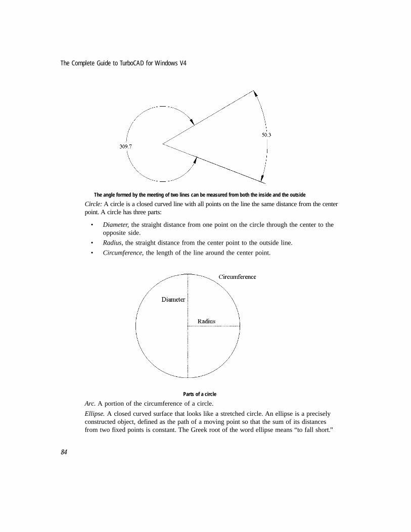
The Complete Guide to TurboCAD for Windows V4
84
The angle formed by the meeting of two lines can be measured from both the inside and the outside
Circle: A circle is a closed curved line with all points on the line the same distance from the centerpoint. A circle has three parts:
• Diameter, the straight distance from one point on the circle through the center to theopposite side.
• Radius, the straight distance from the center point to the outside line.
• Circumference, the length of the line around the center point.
Parts of a circle
Arc. A portion of the circumference of a circle.
Ellipse. A closed curved surface that looks like a stretched circle. An ellipse is a preciselyconstructed object, defined as the path of a moving point so that the sum of its distancesfrom two fixed points is constant. The Greek root of the word ellipse means “to fall short.”
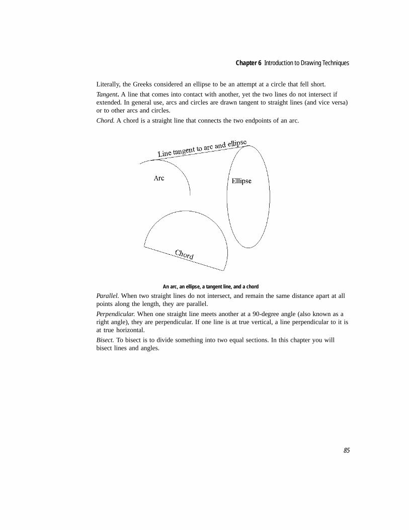
85
Chapter 6 Introduction to Drawing Techniques
Literally, the Greeks considered an ellipse to be an attempt at a circle that fell short.
Tangent. A line that comes into contact with another, yet the two lines do not intersect ifextended. In general use, arcs and circles are drawn tangent to straight lines (and vice versa)or to other arcs and circles.
Chord. A chord is a straight line that connects the two endpoints of an arc.
An arc, an ellipse, a tangent line, and a chord
Parallel. When two straight lines do not intersect, and remain the same distance apart at allpoints along the length, they are parallel.
Perpendicular. When one straight line meets another at a 90-degree angle (also known as aright angle), they are perpendicular. If one line is at true vertical, a line perpendicular to it isat true horizontal.
Bisect. To bisect is to divide something into two equal sections. In this chapter you willbisect lines and angles.

The Complete Guide to TurboCAD for Windows V4
86
Parallel lines, perpendicular lines, and a line bisecting an angle
Polygon. A polygon is an object with three or more straight sides that form a closed figure.A regular polygon is a polygon with all sides the same length.
�������
����
��������
����������
��������
����
��������
A variety of polygons
Triangle. A triangle is a three-sided polygon. It has three straight lines and three interiorangles. An equilateral triangle is one with each side of equal length.
Rectangle. A rectangle is a four-sided polygon in which all angles are right angles andopposite sides are parallel.
Square. A square is a four-sided polygon in which all angles are right angles and all sidesare the same length. By definition, a square is also a rectangle.

87
Chapter 6 Introduction to Drawing Techniques
Construction TechniquesThe rest of this chapter covers a variety of construction techniques using lines, angles andpolygons. Chapter Ten will cover arcs, circles, ellipses, curved objects and theirrelationships to other objects. As you move from one example to the next, think about howyou can take advantage of these techniques in your own design and drafting work. A fewnew commands will be presented along the way.
These construction techniques are presented in a generic fashion, so that you can use thesteps in a real drafting setting as required. To practice them now, start each technique bydrawing the required line or lines.
If you were to enroll in a traditional drafting course using pencil and paper, you would studythe concepts presented below, but the methods used would be much different. The firsttechnique is a good example of the tremendous difference between manual draftingtechniques and automated drafting using a program like TurboCAD.
Bisect a Line with a Point
The first geometric construction technique taught in a manual drafting class is how to bisecta line. Using manual methods, bisecting a line requires the use of a straightedge and acompass. Two arcs and a second line must be drawn to correctly bisect the line. The processtakes several steps. The technique is much easier in TurboCAD:
1. Given any straight line, select Middle Point from the Snap toolbar (left side ofscreen). All other Snap tools should be off.
2. Click on any point along the line. TurboCAD will calculate the exact center of thepoint, bisecting it for you. You may optionally select Middle Point Snap as a localsnap (active one time only) with a right-click when you need it.
If you need to draw from the bisection point, the Line tool should be active before youselect Middle Point Snap. If you need to mark the location, select a point mark from thePoint tool on the Select Entity toolbar before selecting Middle Point.
A straight line marked with a point
Bisect a Line with a Perpendicular Line
1. Given a single line at any angle, start by making sure all Snaps are off. Click the NoSnap button in the Snaps toolbar.

The Complete Guide to TurboCAD for Windows V4
88
No Snap tool icon
2. Select Parallel Line from the Single Line fly-out toolbar.
Parallel tool icon
3. Click on the existing line. Press <Tab> twice and type a number to set the distancebetween the two parallel lines. End by pressing <Enter>. This distance will becomethe length of your perpendicular line. One-half-inch (.5) was used in the illustration.
Draw a line parallel to the existing line
4. Click and hold on the Parallel Line tool icon, until the fly-out toolbar appears. SelectSingle Line.
5. Select Middle Point Snap from the Snaps toolbar.
Middle point snap tool
6. Click on each line. A new line will connect the midpoints of each parallel line. Thisnew line is perpendicular to the original line.
7. Delete the extra parallel line.
Draw a Line at a Specific Heading
1. Select the Line tool.
2. Start the line where required, using any snap tool if needed.
3. Type the length of the line in the Length field on the Edit Bar. Press <Tab> to selectthe highlighted field in the Edit Bar or simply type and the figures will appear in thehighlighted field.

89
Chapter 6 Introduction to Drawing Techniques
Edit bar, showing Length and Angle of a line
4. Press <Tab> to select the Angle field of the Edit Bar. Type the angle (the requiredheading of the line) and press <Enter>.
NOTE: It does not matter whether TurboCAD is in Absolute, Relative or Polar mode. The EditBar will display Length and Angle when the Line tool is selected.
Bisect an Angle
To bisect an angle is to divide an angle equally with a third line. Given any two lines thatmeet at a common endpoint to form an angle, use Fit Radial Copy to draw a line that bisectsthe angle. This method creates an extra line that must be deleted when the angle has beenbisected.
The line to select for the Fit Radial Copy is the one that must be copied counterclockwisetoward the other line. Depending on the orientation of the lines and the angle to bisect, theline to copy might be above or below, left or right, of the second line. Use the illustrationsas a guide to see how the procedure works.
1. Draw two lines as illustrated below. Use No Snap or Grid Snap to draw the first line;use Vertex Snap (with all other snaps off) to draw the second.
2. Click on the Select tool.
3. Make sure Vertex is the only active snap.
4. Select the line that is on the clockwise side of the angle.
5. From the menu, select Edit|Copy Entities|Fit Radial.
6. The prompt reads “Define the center of the copy process.” Click on the commonendpoint of the two lines.
7. In the Edit Box, select the value for Sets and type 3.
8. The prompt reads “Define the angle to fit the copies in.” Click on the distant endpointof the second line.
9. A new line appears between the first two, which bisects the angle. An extra line hasalso been created; it is on top of the second line (the line not copied). Select it andpress <Delete>.
☞

The Complete Guide to TurboCAD for Windows V4
90
Bisecting an angle with a line
Divide an Angle Into Any Number of Parts
With only one change, the steps above used to bisect an angle can also be used to divide anangle into any number of equal parts. Instead of typing 3 in the Sets field of the Edit Bar,type a number that is one higher than the number of ways you need to divide the angle.Remember to delete the extra line on top of the line which was not copied.
Draw a Line Parallel to an Existing Line
TurboCAD has a double line command, which you can use when you need to draw twoparallel lines. But when you need to create a line that is parallel to an existing line, use theParallel Line tool, as described in Chapter Five, and as used in the technique above to assistin drawing a perpendicular bisecting line.
Divide a Straight Line into Proportional Parts
Two methods are available to divide a straight line into proportional parts. The firsttechnique does not “break” the line into separate pieces, but marks off equal distances alongthe line, just as you would on paper with a pencil and a ruler. This technique uses the Menu:Edit|Copy Entities|Linear command to copy a Point marker along the distance of the line.Once the points are placed along the line, they can be snapped to with the Vertex Snap tool.
The second technique to divide a straight line into proportional parts used Node Edit, and isdiscussed in detail below.

91
Chapter 6 Introduction to Drawing Techniques
Divide a Straight Line into Proportional Parts using Linear Copy
1. Draw a line, using any construction method of snap you prefer.
2. Click the No Snap tool.
3. Press and hold on the Point tool until the fly-out toolbar appears. Select the Starshape (or any other shape you prefer).
4. Click Vertex Snap. Click on one endpoint of the line to place a star.
5. Use the Select tool to draw a closed selection window around the star. (To close theselection window right-click to get the local menu and turn off Open Window mode.)
6. From the menu select Edit|Copy Entities|Fit Linear.
7. The prompt reads “Select the final position of the reference point.”
8. Press the <Tab> key until Sets is highlighted in the Edit Bar. Type a value that is onehigher than the number of line segments you need to identify.
9. Click on the opposite end of the line to shift activity back to the drawing screen, andagain to select the end of the line for the copy command. The stars will copy alongthe line.
Divide a Straight Line into Proportional Parts using Node EditNodes are hidden markers that identify elements of geometric objects in TurboCAD. Astraight line, for example, has two nodes, one at each end. A triangle drawn using IrregularPolygon has three nodes, one at each corner.
In Node Edit mode you can reshape entities by directly manipulating nodes. Appendix B ofthe TurboCAD 4 for Windows User Manual lists detailed instructions for using Node Editfor a wide variety of tasks. One of the available options in Node Edit is to divide linesegments into any number of subsegments of equal length.
1. Draw a line, using any construction method of snap you prefer.
2. Select the line.
3. Right-click to summon the Local Menu. Select Node Edit.
The appearance of the selection changes when you shift to Node Edit mode. Instead of aselection box with handles, you will see highlighted objects with nodes displayed as bluerectangles.
4. Place the mouse cursor on the line.
5. Right-click to open the Local Menu and choose Segment Divide. The DivideSegment By dialog appears.

The Complete Guide to TurboCAD for Windows V4
92
Divide Segment By dialog
6. Enter the number of parts into which you want to divide the line, then press <Enter>.
7. Click anywhere on the Paper to deselect the line.
The line looks no different unless selected for Node Edit. But now the line has nodes thatdivide it into proportional segments. You can snap to any of these nodes with Snap Vertex —they do not need to be visible.
Draw the Golden Mean of a LineThe golden mean is a length that represents the golden ratio, a distance used by ancientphilosophers and modern designers. The relationship between a line and its golden mean (asin drawing the sides of a rectangle or right triangle) is universally appreciated asaesthetically pleasing. Given any line, the golden mean of that line has a ratio of .618 to 1.For example, if a given line is 1 unit in length, that line's golden mean will be .618 units inlength.
To draw the golden mean of a line in manual drafting, it is necessary to place three arcs andan extra line. But in TurboCAD it is much easier. If you know the length of the original line,use the Windows Calculator (or pencil and paper) to multiply the length by .618. Theproduct is the length of the line's golden mean. Use the Edit Bar to set the length of the newline.
Follow the steps below to draw a right triangle; the height will be the golden mean of thebase. The distance of the base line in this example will be 3.65 inches. You can also use thisprocedure to draw a rectangle of golden mean proportions.
1. Select Irregular Polygon from the Line fly-out toolbar, and Ortho Mode from theSnaps tool bar.

93
Chapter 6 Introduction to Drawing Techniques
Irregular Polygon tool icon (left) and Ortho Mode tool icon
2. Click on the drawing sheet to start the triangle. Move the cursor to the right, thenpress <Tab> to switch to the Edit Bar. Type 3.65 <Enter> to set the length of thebaseline.
3. Move the cursor up, then press <Tab>. Type 2.557 (the product of 3.65 times .618)and press <Enter> to set the height of the triangle.
4. Right-click and select Finish from the Local Menu. TurboCAD will close the triangle.
2.56
3.65
The ratio of the height to the base is the ratio of the golden mean (.618:1)
Construction Lines and Circles
As you draw, there may be times when you would like to use a line or circle for visualreference, but don’t want to add a new entity to the drawing. Use a construction line orcircle for this purpose. From the menu, select Insert|Construction and select one of sixchoices : Horizontal, Vertical, Angular, Center and Point Circle, Double Point Circle, andTriple Point Circle. If you select a line, it will cross the entire desktop. Construction circlesare drawn to the size you specify.
You can place construction lines and circles with snaps, and can snap to them with anyrelevant snap command.

The Complete Guide to TurboCAD for Windows V4
94
Construction lines appear as dot-dash lines in a drawing
Construction lines exist on their own layer, called $CONSTRUCTION. You can edit theirappearance (line type and color) by editing the $CONSTRUCTION layer (Menu:Options|Layer). Construction lines are for visual reference only, and cannot be selected likean entity or an object (with the exception of Nearest Entity Snap). Use the options at Menu:Edit|Clear to delete construction lines.
Aligning Objects
To create drawings in TurboCAD is to move back and forth between phases of drawing(when you create) and editing (when you modify). At times, you might realize that someobjects in the drawing need to be rearranged so that they are aligned to each other.TurboCAD offers seven align commands for this purpose, found in the Format menu.
To use any of these commands, select the objects you wish to align:
Align Bottom will move the selected objects to the bottom of the selection’s bounding box.
Align Along Line will move the selected objects along a construction line that you place.
Align Middle will center the selected objects vertically in the selection’s bounding box.
Middle alignment, before (left) and after
95
Chapter 6 Introduction to Drawing Techniques
Align Top will move the selected objects to the top of the selection’s bounding box.
Align Left will align the left edges of the selected objects along the left edge of thebounding box.
Align Center will center the selected objects horizontally within the bounding box.
Align Right will align the right edges of the selected objects along the right edge of thebounding box.
Taking Advantage of Construction TechniquesThe techniques explained in this chapter have one basic premise in common with manualdrafting techniques—they must be practiced if you intend to use them regularly. As youbegin to create your own projects, look for opportunities to use the techniques presented inthis chapter. Situations such as the need to bisect an angle, divide a line into equal segments,or align objects are fairly common.

The Complete Guide to TurboCAD for Windows V4
96

7Editing the CAD Drawing
Freedom to Create a Perfect Design
As you begin to draw with TurboCAD, you will find the ease and speed of drawingencourages you to make changes as you go along. Instead of using a rubber eraser, you canuse TurboCAD’s editing and modification commands to quickly rearrange, reshape, copy,replace or otherwise alter any part of a drawing.
The ability to make changes quickly and easily is part of what makes a CAD programsuperior to manual drafting. The experienced manual draftsman can quickly put lines onpaper. But when it comes to making changes, the manual draftsman is left in the eraser dustby the power and versatility of a good CAD program.
The freedom to make changes is part of what makes TurboCAD a tool for both design (thecreative process of deciding features) and drafting (the graphic representation of a design).
Edit or Modify?Generally speaking, the phrase used to describe making changes to a CAD drawing isediting. But the commands in TurboCAD for making changes have been organized in twocategories: Editing and Modifying. There is a menu for each, the Edit menu and the Modifymenu, as well as a toolbar for each. For our purposes, the following definitions apply.
Editing is manipulation of existing objects. If you need to copy an entity, remove it, move it,or place it in a file created by another program, you are editing. Many editing commandsmake use of the Windows clipboard. Under this definition, editing usually means theoriginal entity is not reshaped, but there are exceptions, to be covered in this chapter.
Modifying is alteration of existing entities. If you need to cut a line, join two lines, orotherwise change the shape of one or more entities, you are modifying.

The Complete Guide to TurboCAD for Windows V4
9 8
There are two practical differences between the tools in the Modify menu and the Editmenu. The first difference involves selection. When you use the Edit menu tools, you mustfirst select the object or objects that you want to edit. Then you execute the operation on theselected object or entity (move, copy, erase, etc.) The Modify menu tools are similar todrawing tools, in that you first activate the tool, and then follow a series of steps to completethe edit. The operation is performed on entities that have not been previously selected.When you finish the operation, the tool remains active so that you can modify anotherobject. You must switch to another tool to shut off the first tool.
The second distinction concerns the difference between objects and entities. As you willremember from Chapter Two, object is a general term that means anything that can bedisplayed in a TurboCAD drawing. This covers not only classical geometric primitives likelines, circles and curves, but also text and bit-mapped images. Objects can be groups ofentities, or other elements of a drawing not easily defined using geometric definitions. Theterm entity is more specific. It means a drawing element created with TurboCAD drawingtools. Entities include single lines, multilines, arcs, circles, polygons, and so forth, as wellas construction lines and circles. Entities are independent geometric elements. They wouldbe at home in a geometry textbook, or a manual drafting course.
Editing tools work on both objects and entities. Modifying tools work only on entities. Inpractice, you use the tool or command that gets the job done, no matter its category.Knowing the difference between editing and modifying is largely a matter of gainingfamiliarity with the available tools.
Modify the Divided TriangleThe rest of this chapter is given over to tutorials that explore the use of various editing andmodifying commands. The first exercise will be to make changes to the triangle drawn inChapter Five, which was divided into sections of equal area. When the exercise wascompleted, the lines which divided the triangle had not been trimmed. You will do so now.
If you have not completed the exercise in Chapter Five, or did not save it, you can quicklydraw a triangle and then draw some single lines over the top of it, to create an approximateversion of the object described below. While the new version won't be divided into areas ofequal size, you can still trim the lines as explained below.
Divided triangle from Chapter Five

9 9
Chapter 7 Editing The CAD Drawing
1. Launch TurboCAD. When the Create from Template dialog appears, click the Openbutton. This allows you to open an existing drawing. In Chapter Five, you weredirected to save the drawing in the IMSI/TCW40/Drawings subdirectory as DIV-TRI(if using Windows 95). Open the drawing from this subdirectory, or from whereveryou saved it.
2. Select Object Trim from the Modify menu. (Object Trim was introduced in ChapterFour.)
3. The prompt at the bottom of the screen reads “Define the cutting edge.”
4. Click on the triangle, which will change color (highlight) to show that it is selected.
5. One by one, click on each section of line outside the triangle. Each line will betrimmed to the triangle as you go.
6. Click on the select tool to end the command.
All intersecting lines have been trimmed to the edges of the triangle
Seeking Out the DetailsTo explore some of the editing and modifying tools, open a drawing that shipped with yourcopy of TurboCAD called WDET.TCW, an excellent wall detail drawing.

The Complete Guide to TurboCAD for Windows V4
1 0 0
����
�������
����
����
��� ��
���
����������
����
����
����
�������������
������ �������� ��
������� ����������
�����������
������������������
��������� � ���
������������
��
����
����
���
�����������
�����������
�����������
��������
���������
�������������
� ��������!�������
���������������������
���������������!���!��
�� �"������
#� "����
$�%�����������
#�"&'���
���������� �"����
����()�������������
"�����������
������"� �"
( '� '���������
"��������������
������� �)�������
WDET.TCW
Notice that two portions of the drawing are circled. The circles identify portions of thedrawing that were to be available separately as details. Follow the steps below to separatethe circled elements from the rest of the drawing.
Before making any changes to WDET, the first item of business will be to save a secondversion of the drawing, so that the original is left intact.
1. Start TurboCAD, and open the drawing WDET.TCW, in the IMSI/TCD4/Samplesdirectory.
2. From the menu, select File|Save As. In File Name, type CH7WDET. Changedirectories, selecting the IMSI/TCD4/Drawings directory. Click on the Save button,and fill in the details in the Summary Info dialog if you desire. Click on the OKbutton to end. The name of the file as listed in the Title Bar will change toCH7WDET.
Explode Groups, Extract Details1. The entire WDET drawing has been gathered together as one group. Click on the
Select tool, click on any part of the drawing, then select Menu: Format|Explode todisassemble the group.

1 0 1
Chapter 7 Editing The CAD Drawing
2. Use Zoom Window to gain a close-up view where the metal coping at the top of thewall is circled. Click on the Zoom Window tool in the View toolbar (right side of thescreen), or select Menu: View|Zoom|Zoom Windows. Draw a selection rectanglearound the circle at the top of the drawing.
Zoom window tool
����
���
���
��
�����������
������������������
��������� � ���
������������
Close-up of the top of the drawing
3. From the menu, select Modify|Object Trim. Click on the circle to select it as thecutting edge for the trim operation.
4. Starting at any point along the circle, click on every object that intersects any portionof the circle. Be sure to click on the portion of each object lying outside the circle.Adjust the view as necessary to get a close-up view each object you trim. The linesand arcs of the roof membrane that intersect the circle can be trimmed, if you zoomin close enough to pick them individually. You will not be able to trim the rectanglethat intersects the bottom of the circle. Leave it for the moment.
Results of the first attempt to trim around the circle

The Complete Guide to TurboCAD for Windows V4
1 0 2
5. Click on the Select tool to end Object Trim.
6. Use Zoom Window to get a close-up view of the rectangle (bottom of circle) that didnot trim.
7. Select the rectangle, then select Format|Explode from the menu. Click on the drawingarea to deselect the rectangle.
8. From the menu, select Modify|Object Trim. Click on the circle to select is as thecutting edge.
9. Click on each line of the rectangle that intersects the circle. Be sure to click on theportions outside the circle. Select the Select tool to end Object Trim.
Remove Unnecessary ObjectsYou want every object that is part of the wall to stay in the circle, but the remaining piecesof the Leaders are not needed. (Leaders are lines—usually with arrows—that are used tolabel objects in a drawing. They will be covered in Chapter 11, Dimensioning.) Erase themnow.
1. Choose the Select tool and <Shift-Click> on each line, arrow, etc., inside the circlebut not a part of the wall detail. They are all found on the right side of the circle.Note that the line and the arrow near the top will need to be selected separately.
2. When all the non-wall objects are highlighted, press the <Delete> key to erase them.
The leader lines inside the circle have been deleted
Selection Rectangle OptionsThe wall elements and the circle are now ready to be moved. But there are many objectsclose to the circle that make selecting the circle and its contents a challenge. Fortunately,there are a variety of selection options in TurboCAD.

1 0 3
Chapter 7 Editing The CAD Drawing
So far in this guidebook, objects have been selected by one of two methods: clicking onthem with the Select tool, or using the Select tool to draw a selection rectangle around theobjects.
The selection rectangle gives different results, depending on whether Open Window mode ison or off. To change this option, click the right mouse button in the drawing area to open thelocal menu, then choose Open Window mode. If the menu item has a check next to it, theoption is on; otherwise the option is off.
Local menu, showing open window mode checked
To use the selection rectangle with the Open Window option on, hold the left mouse buttondown and move the cursor, creating a rectangle over an area that contains any part of theobjects that you want to select, then release the mouse button. If any portion of an object isinside the rectangle, the entire object will be selected. This includes nodes and vertices ofthe object.
To use the selection rectangle with the Open Window mode off, hold the left mouse buttondown and move the cursor, creating a rectangle over an area that contains the objects youwant to select in their entirety, then release the mouse button. If any portion of an object isoutside the rectangle, it will not be selected.
Selection rectangle with Open Window option on
rectangle selectsboth objects
(symbols)

The Complete Guide to TurboCAD for Windows V4
1 0 4
Selection rectangle with Open Window option off
Other Selection OptionsTwo additional selection methods are available from the Edit menu, Select All and SelectBy. Select All (keyboard shortcut: <Ctrl-A>) will select every object in the drawing. SelectBy has six options, Query, Entity Type, Color, Layer, Attribute, and Fence.
Select By Query allows you to approach the entities and objects in a TurboCAD drawing aselements in a data base. A selection chart appears, and you can enter values based on avariety of attributes. The method of operation is similar to that used by data basemanagement software. Select By Query is helpful when searching large drawings forspecific symbols and blocks, since they can be identifed by name.
Select By Entity Type is used when you need to select all objects of a given type, such asBezier curves. When the command is chosen, a dialog appears on-screen. Every possibletype of object in TurboCAD is listed. You can use this dialog to select any type of object orcombination of types, using common Windows list box selection techniques. If you wish toadd objects of these types to a current selection, place a check in the Add to the CurrentSelection check box. If this box is not checked, then any currently selected items will bedeselected as the new objects are selected. All objects in the drawing meeting the selectioncriteria will be highlighted.
rectangle selectsonly completely
enclosed objects

1 0 5
Chapter 7 Editing The CAD Drawing
Select by Entity Type dialog
Select by Layer allows you to name one or more layers. When you do so, all objects onthose layers will be selected. If you are organizing your drawings by layers (discussed inChapter Nine), this selection option is very helpful. The next illustration shows the Select byLayer dialog for WDET.TCW.
Select by Layer dialog
Select By Fence lets you select a set of objects by drawing a polygon “fence” around them.The Open Window mode affects the action of the fence. If Open Window mode is on, anyobject that intersects or is inside the fence will be selected. If Open Window mode is off,only those objects completely inside the fence will be selected. Creating this fence isexactly like the using the Irregular Polygon drawing tool. You will use this tool in the stepsbelow to select the circle and the details inside.

The Complete Guide to TurboCAD for Windows V4
1 0 6
Select and Move Details1. From the menu choose Edit|Select By|Fence.
2. Click on a point just outside the circle to start the selection fence.
3. Right-click to open the local menu. Make sure Open Window mode is off (notchecked). If it is checked, click on it to shut it off.
4. Continue around the circle by clicking and moving the mouse. Each point you definewill become a new vertex (corner) of an irregular polygon fence. A rubberband linewill connect back to the origin of the fence as you draw. Make sure that any objectsyou wish to select are contained within the fence.
5. The area by the roof will be a tight fit. Use Zoom Window (or Zoom In, <Gray +>)interactively as you draw the fence if necessary to get a close-up of the right side ofthe circle.
6. Use Zoom Out (< Gray + > key on the numeric keypad or the Zoom Out icon in theView toolbar, right side of the screen) to get a wider view after drawing the fencethrough the area between the roof and the circle.
7. When you have worked all the way around the circle, right-click in the drawing areato access the local menu. Choose Finish to complete the fence and select the objects.
8. Click on Zoom Full View in the View menu to see the entire sheet.
9. Click (not on the reference point, but anywhere inside the selection window) and dragthe selected objects (the circle and the top of the wall) to an open area on the sheet tothe right.
10. Click anywhere in the drawing area (outside the selection window) to deselect theobjects.
11. Use Zoom Window to gain a close-up of the objects.
The circle and wall detail, separated from the rest of the drawing

1 0 7
Chapter 7 Editing The CAD Drawing
Cut and PasteSave the wall detail as a separate drawing, for use with the exercises in Chapter Twelve. UseCut and Paste, two Edit menu commands exactly like their counterparts in many otherWindows programs. Menu: Edit|Cut removes the selection to the Windows clipboard; Menu:Edit|Paste places a copy of the contents of the Windows clipboard.
Two features of the Windows clipboard should be remembered. First, it only holds oneselection at a time. Second, when you use the Paste command in a Windows program, acopy of the item in the clipboard is retrieved. You can Paste the item an unlimited number oftimes.
If for some reason you don’t want the wall detail removed from this drawing, substituteCopy (<Ctrl-C> or Menu: Edit|Copy) for Cut in the steps below.
1. Adjust the screen view so that the entire wall detail is visible.
2. Use any selection method you prefer to select the detail and the circle.
3. Press <Ctrl-X> or select Menu: Edit|Cut to remove the detail to the Windowsclipboard.
4. From the menu, choose File|New. Select Normal as the template, and close the SetupDialog if necessary.
5. Press <Ctrl-V> or select Menu: Edit|Paste.
6. Press <Ctrl-S> or select File|Save from the menu.
7. Name the new drawing CH12DET, and save it to the DRAWINGS folder orsubdirectory. Fill in the details for the Summary Info dialog if you like.
8. Close the drawing (<Alt-F> <C> or Menu: File|Close). The original drawing returnsto the screen.
9. There is no further need for CH7WDET in this exercise. Save and close the drawing.
NOTE: It was not necessary to close the first drawing to create a new drawing. TurboCADallows you to open many drawings at once. The limit depends on available memory.
Practice Makes PerfectTake a few moments now to create a new drawing that looks like the one below. Use theLine, Double Line and Rectangle tools. Snap to Grid will make it easy to keep the linesstraight.
☞

The Complete Guide to TurboCAD for Windows V4
1 0 8
Draw this set of lines for the next exercise
After reading the descriptions of the various Modify commands below, take a few minutes topractice each command on some part of this drawing. Feel free to add or erase elements asnecessary.
Chamfer and FilletWhen lines come together to make corners, you don’t always want them to meet at a point.You may need to design an object with rounded corners, or you may need to create beveledcorners. TurboCAD has a Modify command for each situation. These are Chamfer (forbeveled corners) and Fillet (for rounded corners).
ChamferChamfer joins two line segments or double line segments with a flattened (beveled) corner.The values used to calculate the chamfer appear in the Edit Bar when the command isactive.
Chamfer before and after
To create a chamfer, you need to specify two distances in the Edit Bar, called Distance Aand Distance B. Distance A is the distance from the point where the chamfer meets the firstline clicked, to the point where the two lines intersect. Distance B is the correspondingdistance on the second line. After specifying these distances in the Edit Bar, click on the two

1 0 9
Chapter 7 Editing The CAD Drawing
lines in the correct order: TurboCAD will draw a beveled corner at the intersection of thetwo lines.
FilletFillet inserts an arc at the intersection of two nonparallel lines. These lines may meet at acommon endpoint or they may overlap. The radius of the arc can be modified whenever thecommand is active by changing the value in the Edit Bar. By default, the radius is one inch.
Fillet before and after
If the radius specified is too large for the arc to fit between the two lines, TurboCAD will beunable to perform the fillet and will display an error message.
TIP: If fillet radius is set to 0, the fillet tool can be used to square off two lines that wouldintersect if connected. The tool extends each line, then inserts an arc of “zero” radius, i.e., noarc at all. This is an alternative to Meet 2 Lines.
Meet 2 LinesUse the Meet 2 Lines tool to shrink or extend two lines or double lines so that endpointsmeet. This function automatically cleans up the corner formed by two double lines.
✔

The Complete Guide to TurboCAD for Windows V4
1 1 0
Two before-and-after examples of using Meet 2 Lines; stars identify click locations
To use this tool, simply click on the two lines. When the two lines are crossed, the two partsof the line that you click on will be preserved; the parts of the lines on the opposite side ofthe intersection will be trimmed.
Cleaning Double Line IntersectionsDouble lines can be handy for a variety of design applications. When two double lines cross,generally the intersection needs to be modified in some fashion. TurboCAD offers two toolsspecifically for cleaning double line intersections, T-Meet 2 Double Lines and Intersect 2Double Lines.
Use T-Meet to form a “T” intersection of two double lines. The first line clicked will extendor shrink to meet the second double line and form the stem of the T.
The steps in using T-Meet are:
1. Select the tool (Menu: Modify|T-Meet 2 Double Lines).
2. Click on the line that will form the stem of the T.
3. Click on the line that will form the top of the T.

1 1 1
Chapter 7 Editing The CAD Drawing
Two before-and-after examples using T-Meet 2 Double Lines; stars identify clicks
Use the Intersect 2 Double Lines tool to clean up the intersection of two double lines.
Before-and-after using Intersect 2 Double Lines
Both double line intersection tools have a special option available from the local menu(right mouse button) when the tool is active. The Cleanup option specifies whether or not acomplete editing of the intersection will take place.

The Complete Guide to TurboCAD for Windows V4
1 1 2
Local menu showing cleanup selected
If Cleanup is active for T-Meet, both sets of double lines will be open. If not, the first doubleline selected will be open (clean), the second will be blocked by the first line. If Cleanup isactive for Intersect 2 Double lines, the intersection will be completely open, like two streetsmeeting at a four-way stop. If Cleanup is not active, the first double line selected will beopen, blocking the second double line where they intersect.
An Infinite Number of UsesThe tools and commands available in the Edit and Modify menus can be used in an infinitenumber of drawing situations. Make a mental note to consider these tools as you start tocreate your own drawings.
Not every command in these two menus has been covered in this chapter. Some havealready been used, and some will be used in upcoming chapters, especially Chapter Ten.

8Text in the CAD Drawing
Providing Context for Images
Text plays a key role in design drawings. It provides context, bridging the gap betweenverbal and visual communications. Place the word Kitchen in a room of a floor plan, and itis immediately clear to the reader that all objects in the room are appliances, cupboards, etc.The one word gives enough context without having to name the objects individually.Anyone looking at the drawing can “read” the objects correctly.
The use of text is an important part of creating successful CAD drawings, as important asany line in the drawing. Placing text in a drawing should not be an afterthought in thedrafting process.
An Extra Benefit for Graphic DesignersText placement tools are available in TurboCAD because they are essential to CAD.Whether you draw homes, stage lighting schematics or pistons, you need text. But thecombination of text and CAD tools makes it possible to use TurboCAD as a graphic designtool. There are ways to manipulate text in TurboCAD to create special effects otherwisepossible only in expensive professional graphic design and publishing software.
The methods of text manipulation discussed in this chapter can be applied to either draftingor graphic design with equal flexibility. Chapter Twelve will cover the use of other non-geometric objects for visual detailing in TurboCAD drawings.

The Complete Guide to TurboCAD for Windows V4
1 1 4
Text and Professional Drafting StandardsTake a look at the letters that make up the words you are reading right now. Examine theirshape, their width, their height. Look for common elements in the letters. These elementsdefine these particular letters as part of a font, a complete character set in a distinctive style.Windows uses a technology called TrueType to generate fonts. The Windows operatingsystem ships with several TrueType fonts, and hundreds more are available for purchase.TurboCAD can place any installed TrueType font in a drawing.
What is a TrueType font? In order to understand the differences between TrueType fonts andother typefaces, lets look briefly at the history of text in CAD software.
The first generation of popular DOS-based CAD programs each used a different method torepresent text. Basically, each letter was a tiny drawing, consisting of lines, arcs andsometimes curves. The typefaces (fonts) used by these programs were copies of typefacesused in manual drafting, where every letter had to be created by hand by the draftsman.Each CAD program had its own technology for generating text. Typefaces created for oneprogram could not be used by another, unless special conversion software was available.
Before CAD, the various drafting professions (primarily architecture and engineering) haddeveloped standards for the appearance of text in drawings. As CAD began to replacemanual drafting, the old standards for typefaces remained in place. But the introduction ofWindows (and to a lesser extent, the Macintosh) has caused a revolution in draftingstandards. The ability to use “real” fonts (as used in publishing) has caused many a draftingprofessional to drop the old-style stick fonts for a modern typeset appearance. But not alldrafting professionals have adopted the new look for their drawings. To meet the needs oftraditional draftsmen using modern tools, TrueType fonts are available for purchase thatlook like the old-style stick lettering. If you will be creating drawings that must meetspecific professional standards, be sure to find out if you are restricted to the use of certainapproved typefaces, or if you have the freedom to use any legible typeface. If there arerestrictions, try to find out if an appropriate TrueType font is available.
The advantage of TrueType fonts, and the primary reason they have become a standardelement in the Windows environment, is their flexibility. TrueType fonts are scalable to anysize without a loss of resolution. Embedded into the architecture of each letter is theprogramming instructions that allow a Windows program to modify the size of the letter asrequired. The internal definition of the letter provides the necessary algorithms to shape theletter correctly at any size required.
Not only do the various drafting professions have standards about the use of fonts, there arealso standards about the size of type in drawings. These standards vary with the profession,and it is beyond the scope of this book to try to teach the various rules. TurboCAD makes iteasy to adjust text to any height, using the drawing units (English or metric) instead ofpoints, the text measurement system used in typography and graphic design.

Chapter 8 Text in the CAD Drawing
1 1 5
NOTE: If you are familiar with points as a unit of measurement for type, you can use pointsinstead of inches (or fractions thereof) by placing your text using Paper Space instead ofWorld Space. The Text Format toolbar, if active, provides the opportunity to set type size inpoints.
If you don’t have a specific set of professional guidelines to go by, use these rules of thumbas you create working drawings:
• Use only one font whenever possible. Use two fonts only if there are two distincttypes of objects being labeled.
• Avoid novelty fonts for working drawings. If you don’t have specialty fonts fordrafting, stick to Ariel, Courier New and Times New Roman.
• When printed to an 8 1/2” x 11” sheet, the largest characters should never be morethan 1/4” tall.
• If you are familiar with points as a measurement for text, remember that 72 pointsequals one inch. When you are working in World Space, TurboCAD uses the currentunit of measurement for text, not points. If you want 18-point text in the drawing, youwould use 1/4” text (18 divided by 72). As explained above, you may want to changeto Paper Space and use points directly.
• If both text and dimensions are used, the dimension text should be no taller than 75percent of the height of text used to label major objects.
• Leader text should be the same size as dimension text. (Dimensions and leaders arecovered in Chapter Eleven.)
Placing Text in a DrawingThe basics of text placement in TurboCAD are simple. Before you start with the exercises inthis chapter, add the Text Format toolbar to your desktop. Select Menu: View|Toolbars.Click on Text Format in the list of available toolbars. When you click the OK button, theText Format toolbar will appear on-screen.
Follow these steps whenever you need to place text in a drawing:
1. Activate the Text tool, in the Insert Entity toolbar.
Text tool icon
2. If you wish to set the font, size, and attributes of text (such as underlining or italic)prior to typing, choose settings from the Text Format toolbar. As an alternative, youcan set text properties by right-clicking on the Text tool, then changing the propertiesin the Text property sheet that appears.
3. Click in the drawing area at the point where you want to place your text. Any snapcommand may be used to identify this location.
☞

The Complete Guide to TurboCAD for Windows V4
1 1 6
4. Type the text that you want to place, using the <Backspace> key to make corrections.Press <Shift> + <Enter> to add a new line of text. To finish the text, press <Enter>, orright-click and choose Finish from the local menu.
Using these steps as a guide, place the phrase (include the misspellings) Drawin byTurbuCAD in a new drawing. Use the Text Format toolbar or the Text property sheet (shownbelow) to set text properties as:
• Font: Courier New
• Height: 0.5 in.
• Style: Bold
• Justification: Left
Text properties dialog, with settings as described above
Make sure either No Snap or Snap to Grid is active.
Editing Text in a Drawing
Once text has been placed in a drawing, it may be edited for content as necessary.
1. Change to the Select tool, and select the line of text. Use either a selection rectangleor click on the line of text.
2. Right-click on the drawing area to summon the local menu, or double-click on theline of text to be edited.
3. Select Properties. The Properties dialog will appear. The selected text will behighlighted in the Attribute field.

Chapter 8 Text in the CAD Drawing
1 1 7
Properties dialog, with the text phrase visible in the attributes field
4. Click somewhere on the line of text to insert a text placement cursor. Use the arrowkeys and <Backspace> (or <Delete>) to change Drawin to Drawn, by to In, andTurbuCAD to TurboCAD. When finished, click on OK. (The <Enter> key will notwork in this situation as an alternative to clicking the OK button.)
Corrected phrase as it appears on the drawing sheet
Reformatting Text in a Drawing
It is OK to change your mind about the format of the text you have placed in the drawing.TurboCAD allows you to adjust all text properties after text has been placed in a drawing.
1. Select the text (if not still selected from the previous exercise).
2. Right-click to summon the local menu. Select Properties.
3. Click the Text tab.
4. Change Style to Italic.
5. Change Height to 0.67 in.
6. Select Underline in Effects.
7. Select Gray in Color. (The complete list of colors available depends on yourcomputer hardware.)
8. Click OK to finish.

The Complete Guide to TurboCAD for Windows V4
1 1 8
Text properties with changes made
Text revisions as they appear on the drawing sheet
Manipulating TextSo far we have edited the text and changed its properties, similar to doing it in a wordprocessor. TurboCAD sees the text as a TrueType font, and treats it accordingly.
NOTE: The use of text is the first example in this book of placing non-geometric entities in adrawing. Chapter Twelve covers the use of other objects that do not conform to the rules ofgeometry.
TurboCAD 4 for Windows has many options for manipulating text, based on the principlethat you can edit or modify the text as:
• a TrueType font
• a group of polygons
• individual polygons
• multilines and fill patterns
Manipulating text as a TrueType fontAs a TrueType font, you can edit the text and change its properties. These properties includenot only the font size, style and color, but also three other categories:
☞

Chapter 8 Text in the CAD Drawing
1 1 9
• Mode;
• Effects;
• Justification.
TrueType Text Mode settings
Text Mode controls how a block of text will respond when resize it using a selectionrectangle. Text set to Standard will stay proportional no matter how it is resized. Scalabletext can be resized non-proportionally by resizing the text block’s selection rectangle.Flexible allows the Obliquity setting to be used. Obliquity sets the text at a specific slant.While this looks like an alternative to setting the text style to Italic, that is not the purpose.The Flexible option, along with an Obliquity setting, is used to prepare text in a drawingthat will be converted to a three-dimensional format. If you use Obliquity in a two-dimensional drawing, the characters are actually slanting out of the plane of the drawing.
TrueType Text Effects settings
Text Effects controls a variety of settings you might require in a drawing, and are self-explanatory. The possibilities are:
• Strike-through
• Underline
• Text Box
• Hidden
• All Caps
TrueType Text Justification settings
In a word processor, text justification refers to how text lines up within the margins of adocument. In TurboCAD, justification refers to how the text lines up inside the selectionrectangle. The three options are Left, Right, and Center.
Manipulating text using ExplodeIf you want more freedom to manipulate the text graphically, you need to explode the text toturn the characters into irregular polygons. The first time you do this, you will turn the textobject into a group of polygons. If you explode the text a second time, it will ungroup sothat each individual character can be manipulated as a polygon. You can resize, stretch,move, flip, or rotate each individual character in either Select Edit or Node Edit mode. Youcan change the pen, brush pattern, or other properties of the multiline by double-clicking onthe selection and changing the settings in the Properties dialog.

The Complete Guide to TurboCAD for Windows V4
1 2 0
Align Text to a Line
It is possible to align text to an existing line in the drawing. It is not necessary to know theangle of the line before aligning the text.
The next sequence introduces the External Text Alignment command. This feature providesprecise control over how text is aligned relative to the point where it is inserted in thedrawing. To activate these options, select the text tool, right-click in the drawing area, andthen choose Align. The command will be followed by two capital letters that vary,depending on the current alignment setting.
The star next to each alignment setting shows you graphically how the text is positionedrelative to the insertion point. There are three vertical positions (top, center, bottom), andthree horizontal positions (left, right, middle) for nine total choices (Top Left, Top Right,etc.).
External Text Alignment dialog
When you reopen the local menu with the Text tool active, the letters next to Align representthe current setting. TL, for example, means the insertion point will be at the Top Left cornerof the text.
Follow these steps to gain experience with the technique.
1. Delete the existing text.
2. Click No Snap, then select the Line tool and draw a diagonal line from roughly thelower left corner of the Paper to the upper right.
3. Click the Text Insertion tool.
4. Move the cursor to the lower left end of the line. Right-click and select LocalSnap|Vertex. Click near the end of the line, which will set the insertion point for thetext you will place.
5. Move the cursor to the upper end of the line.
6. Right-click and select Angle.
7. Right-click and select Local Snap|Vertex. Click on the upper end of the line, settingthe angle for text insertion.
8. Right-click and select Align. The External Text Angle dialog will appear.

Chapter 8 Text in the CAD Drawing
1 2 1
9. From the choices that appear, select the left icon on the bottom row, as shown above,and click on the OK button. This will place text using the bottom of the first letter asthe point of insertion.
10. Type "Text on a line" and press [Enter].
Text aligned with the line
TIP: Manipulating text in TurboCAD can cause stray pixels to appear on-screen as you work.Press <F5> to force a screen redraw at any time.
Align Text to an Arc or Circle
If you really want to get fancy, you can align text to an arc or circle, real or imagined. Thesequence below will align to an existing circle. To align text in a radial pattern withoutaligning to a specific circle or arc, skip the step that places the text character on the entity.For this example, use the phrase Love makes the world go around.
NOTE: This technique uses Fit Radial Copy, introduced in Chapter Six.
1. Erase all existing objects on screen. Draw a large circle.
2. Count the number of characters in the phrase to be placed in the drawing. Be sure tocount spaces as characters. If you plan to align text around the circumference of acircle, count two or three extra characters for space at the end. Adding two extraspaces (and no period) to Love makes the world go around totals 32 characters.
3. Select the Text tool. Click Quadrant Snap in the Snaps toolbar.
✔
☞

The Complete Guide to TurboCAD for Windows V4
1 2 2
Quadrant snap tool
4. Click on the top of the circle and type L, the first letter of the phrase. Press <Enter>.
5. Click on the Select tool, and select the letter.
6. From the menu, choose Edit|Copy Entities|Fit Radial Copy.
7. Click on Arc Center in the Snaps toolbar. Deselect Quadrant Snap.
Arc center snap tool
8. Click on the circumference of the circle. The Fit Radial Copy will then snap to thecenter of the circle.
9. Press the <Tab> key until Sets is highlighted in the Edit Bar. Type the number ofcharacters you need (32 in this example).
10. Press the <Tab> key again to highlight Angle. Type 360 and press <Enter>. The letterL will be copied around the circle, making a total of 32 copies.
�
�
�
��
�
�
�
�
�
�� �
�
�
�
�
�
��
�
�
�
�
�
�
��
�
�
�
32 copies of ‘L’ around a circle
11. Decide where on the circle you want the phrase to begin. In this example, start on theupper left side of the circle (where 10 would be on a clock).
12. Select the letter one character clockwise from the starting point of the phrase, thendouble-click on the letter to access the Properties dialog. Click on the general tab ifnot already active.
13. The letter will be highlighted in the Properties dialog. Type o, the second character ofthe phrase. Click OK.

Chapter 8 Text in the CAD Drawing
1 2 3
14. Select the next letter, right-click, select Properties, and type v, the third letter of thephrase. Click OK.
15. Repeat the process to change every letter in sequence.
��
�
�
��
��
�
�
�
�
�
�
�
�
�
�
�
�
�
Finished circle with “Love makes the world go around” on it
TIP: To place spaces between the words, don’t bother right-clicking for the Properties dialog.Just delete the character.
Manipulating Text as Graphic Elements
It was not necessary to explode the text in any of the techniques already given. If you wantto create special graphic effects with text, you must explode the characters first.
1. Delete all objects on the screen, or save your work and start a new drawing.
2. Select the Text tool. In the Text Format toolbar, change the font to Ariel, the size to 1in., and select Bold.
Text toolbar with settings as described
3. Select Snap to Grid from the Snaps toolbar.
4. Click to the left of center on the Paper, and type your initials or TCD (for TurboCADDesigns). Press <Enter>.
5. Switch to the Select tool. Select the text, then select Menu: Format|Explode.
6. With the letters still selected, use Explode again. Then click anywhere in the drawingarea.
✔
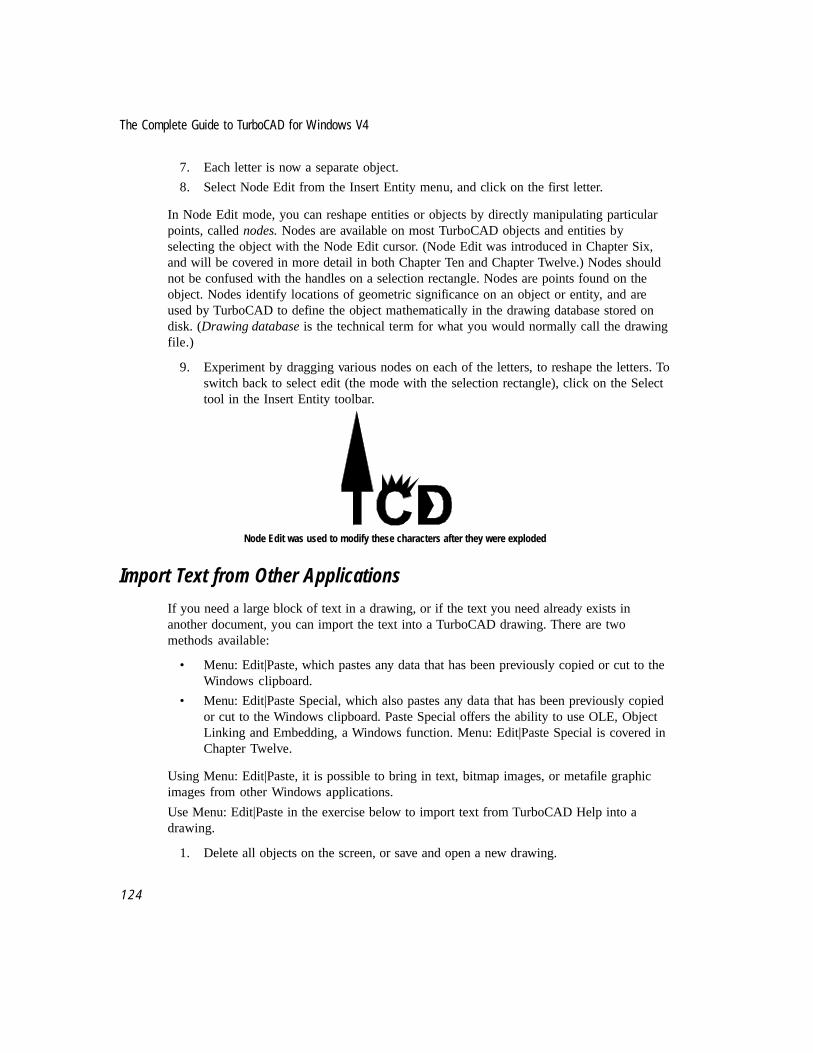
The Complete Guide to TurboCAD for Windows V4
1 2 4
7. Each letter is now a separate object.
8. Select Node Edit from the Insert Entity menu, and click on the first letter.
In Node Edit mode, you can reshape entities or objects by directly manipulating particularpoints, called nodes. Nodes are available on most TurboCAD objects and entities byselecting the object with the Node Edit cursor. (Node Edit was introduced in Chapter Six,and will be covered in more detail in both Chapter Ten and Chapter Twelve.) Nodes shouldnot be confused with the handles on a selection rectangle. Nodes are points found on theobject. Nodes identify locations of geometric significance on an object or entity, and areused by TurboCAD to define the object mathematically in the drawing database stored ondisk. (Drawing database is the technical term for what you would normally call the drawingfile.)
9. Experiment by dragging various nodes on each of the letters, to reshape the letters. Toswitch back to select edit (the mode with the selection rectangle), click on the Selecttool in the Insert Entity toolbar.
Node Edit was used to modify these characters after they were exploded
Import Text from Other Applications
If you need a large block of text in a drawing, or if the text you need already exists inanother document, you can import the text into a TurboCAD drawing. There are twomethods available:
• Menu: Edit|Paste, which pastes any data that has been previously copied or cut to theWindows clipboard.
• Menu: Edit|Paste Special, which also pastes any data that has been previously copiedor cut to the Windows clipboard. Paste Special offers the ability to use OLE, ObjectLinking and Embedding, a Windows function. Menu: Edit|Paste Special is covered inChapter Twelve.
Using Menu: Edit|Paste, it is possible to bring in text, bitmap images, or metafile graphicimages from other Windows applications.
Use Menu: Edit|Paste in the exercise below to import text from TurboCAD Help into adrawing.
1. Delete all objects on the screen, or save and open a new drawing.

Chapter 8 Text in the CAD Drawing
1 2 5
2. Select the text tool, so that the Text Format toolbar is active. Change the text size to.25 in or smaller.
3. From the menu, select Help|TurboCAD Help Topics.
4. Select Search. Type Paste and press <Enter>.
TurboCAD help screen for the Paste command
5. Move the cursor onto the body of the text. Highlight the first three lines (Menu:,Hotkey:, and Toolbar:)
6. From the Help screen menu, select Edit|Copy, or press <Ctrl> + <C> to copy thehighlighted text.
7. Double-click on the Control Menu Box to close the Help screen.
8. Back in TurboCAD, select Menu: Edit|Paste, or press <Ctrl> + <V>. The text fromthe help screen will appear in the drawing with a selection rectangle. Click anywhereon the drawing area to deselect.
Text from TurboCAD Help pasted into a drawing

The Complete Guide to TurboCAD for Windows V4
1 2 6
The Best of Both WorldsSome people relate better to graphic images and visual communications. Others relate betterto words. TurboCAD bridges the gap by offering a robust set of text tools. Not only can youannotate technical drawings to provide context and complete explanation, but you can useTurboCAD as a graphic design sketchpad.
Some of the features and concepts introduced in this chapter will be revisited later. Text is anon-geometric object in TurboCAD, and has aspects in common with other objects such ashatches, color fills, bitmaps, and metafiles.

Chapter 8 Text in the CAD Drawing
1 2 7

The Complete Guide to TurboCAD for Windows V4
1 2 8

9File and Data Management
Organizing the Information You Create
First and foremost, CAD programs are not about pictures. They are about data. A design isthe visual representation of information — data. The CAD program helps you organize thisinformation into a recognizable visual form. Using drafting and editing tools, you createspecific images that convey specific meaning.
In addition to the geometric entities and other objects you draw, TurboCAD offers otherways of organizing and displaying the information in a drawing. This chapter covers thefundamentals of organizing and managing the varieties of data generated by a designer ordrafter.
Comparing Drawings to DocumentsTo understand how a drawing conveys information, compare a TurboCAD drawing to atypical document made with a word processor.
In the document, the basic element is the character. In English, characters are the 26 letters,capital and lower case, plus punctuation and math symbols. In the drawing, the basicelement is the point, a geometric element that has position but no size.
In a document, we combine groups of characters to create a word. By itself, each characterhas no inherent meaning. But when combined to make words (or equations, if dealing withmath), each grouping carries an idea. Therefore, we must be careful when we put characterstogether. For example, unite and untie use exactly the same letters, in almost the same order,but their definitions are opposites.
In a TurboCAD drawing, the counterpart of a word is the entity. As defined in Chapter Two,lines, arcs, circles, and the other primitive objects in TurboCAD are all entities. They are

The Complete Guide to TurboCAD for Windows V4
1 3 0
carefully arranged groups of points, and this arrangement determines their geometricdefinition. For example, a circle is defined by the location of its center and its radius. All thepoints on the circle then “line up” so that they are exactly the same distance from the center.
Words and equations in a document may be given emphasis. In this book, for example, wemake use of Capitalization, bold type, italic type, and changing fonts to giveemphasis. Other forms of emphasis in a document may be variations of font styles, the useof small capital letters, changes in type size, and if available, color. Each of these variationsin emphasis is an attribute, not of the word itself, but of how the word appears in print.
It is also possible to emphasize entities in TurboCAD, with the use of such attributes ascolor, line pattern, pen width, and the layer the object resides on. Each of these elementswill be defined in this chapter, and suggestions for use offered.
Words combine, with or without emphasis, to form a sentence. Sentences combine to form aparagraph, and paragraphs to form the document. Each level imparts information, and as theparts become a whole the author presents the message.
In TurboCAD, entities combine to form objects, objects may be formed into groups, andboth are presented together to form a total concept, the design message. In both thedocument and the drawing, the full intent of the designer comes through when the entitiesare seen as a unified, single work.
A reader may analyze some parts of a document separately. For example, a memorandumfrom a company CEO may outline five steps to be taken by various departments. Readersfrom each of these departments will read the entire memo, but will pay especially closeattention to steps involving their particular department.
Most CAD drawings will also be analyzed on a piece-by-piece basis. Consider how thedrawings for a new house will be used. The appliance delivery crew will look to see whereappliances are to be installed, plumbers will look at the plans for the plumbing, andelectricians, carpet installers and other subcontractors will focus on the parts of the drawingrequiring their attention. All will look at how their part of the job fits into the completedesign. This detailed analysis of a CAD drawing can be made easier by organizing andhighlighting information in the drawing.
CAD Management SystemsFor each entity you draw in TurboCAD, you can define:
• Pen color
• Pen width
• Line pattern
• Dash Scale
• Alignment
• Layer
• Width scaling

Chapter 9 File and Data Management
1 3 1
In addition, each object can be given its own label or explanation, known as an attribute.There can be a virtually infinite number of colors, widths, patterns, dash scales and layers.If you have only been thinking of CAD drawings in terms of thin solid black lines, thissudden availability of infinite variety may be a little overwhelming.
Most experienced drafters and designers rely on a CAD management system to guide themin the selection of these variables. The system is either the result of personal decisions,company standards, the advice of a professional organization, or tradition. You should seekout examples of standards that are relevant to your situation, and begin to use them in yourdesign projects. Lacking the availability of such standards, you can still organize yourdrawings using color, line type, and the other options. In a construction plan, for example,you could use color to identify various raw materials such as wood, masonry, and sheetrock. Wiring could be in one color (or 120v in one color, 220v in another), as couldplumbing.
Various elements of information management and presentation discussed below will beaccompanied by a brief hands-on section. Instead of taking the time to draw a variety ofobjects, and then modify their color, layer data, etc., the drawing TECHNIC1.TCW,included with your copy of TurboCAD, will be used for exploring some of these options.
Properties of EntitiesTurboCAD provides a variety of ways to display and record entities in a drawing. Theavailable settings are controlled in the Properties dialog, available from the menu atFormat|Properties. This menu item is not available unless an entity in the drawing isselected; the settings you see in the Properties dialog belong to the selected entity.
For all entities, the Properties dialog has three sections, each called a Properties sheet:
• General
• Pen
• Brush
Additional property sheets for Double Line, Curve, Point, Text and the various dimensionsstyles, appear in the Properties Dialog only if one of these entities is selected.
General Properties
The General properties sheet lets you select a layer and add an attribute to the entity. Acomplete discussion of layers follows shortly. A text attribute is a brief explanation that youcan link to the entity. For example, if a polygon represents a bolt, you can select thepolygon and list a part number or size as the text attribute for the polygon. If a specific textattribute is not created by the user, the name of the entity (line, polygon, curve, etc.) willappear.
The Selection Info palette, introduced in Chapter Six, will display the text attribute of a
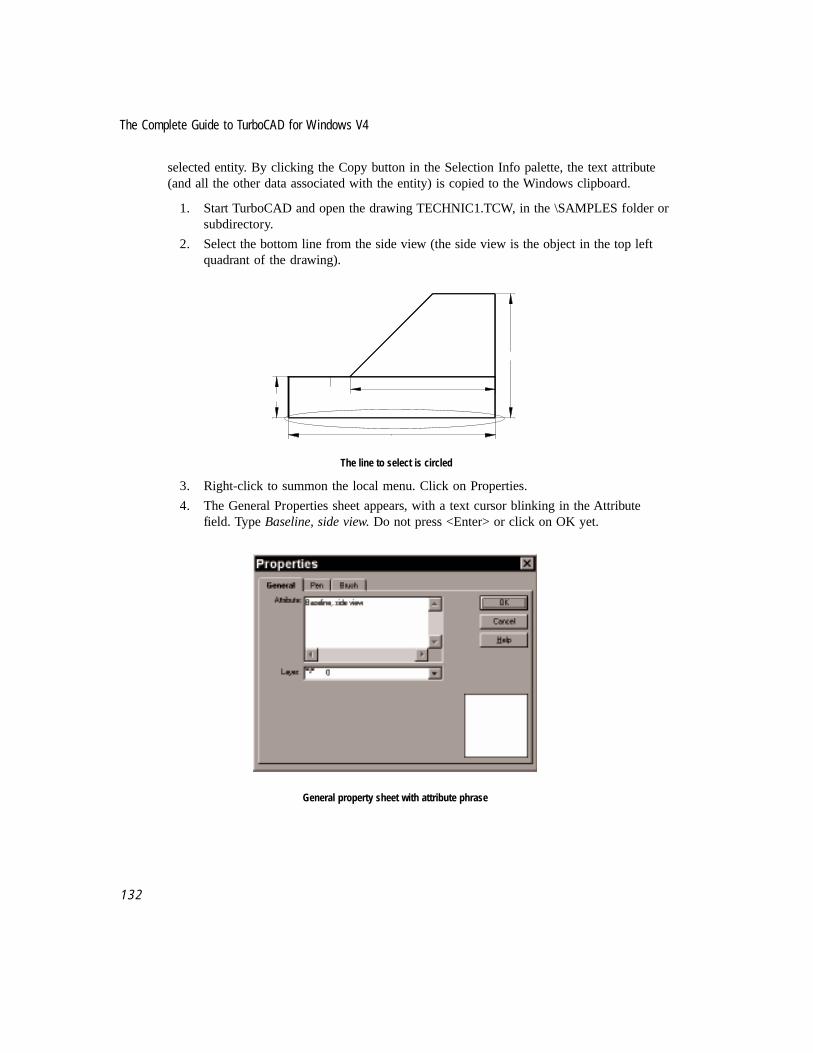
The Complete Guide to TurboCAD for Windows V4
1 3 2
selected entity. By clicking the Copy button in the Selection Info palette, the text attribute(and all the other data associated with the entity) is copied to the Windows clipboard.
1. Start TurboCAD and open the drawing TECHNIC1.TCW, in the \SAMPLES folder orsubdirectory.
2. Select the bottom line from the side view (the side view is the object in the top leftquadrant of the drawing).
6
2
7
1
The line to select is circled
3. Right-click to summon the local menu. Click on Properties.
4. The General Properties sheet appears, with a text cursor blinking in the Attributefield. Type Baseline, side view. Do not press <Enter> or click on OK yet.
General property sheet with attribute phrase

Chapter 9 File and Data Management
1 3 3
Pen Properties
The Pen properties sheet controls the look of lines in the drawing. In this context, linesmeans all geometric entities, not just objects created by the Line tools. The main elementsare pattern, color, and thickness.
Twenty-six line patterns are available in TurboCAD. The ten most commonly used in all thevarious drafting professions are shown below. The others 16 patterns represent variations onthese ten basic patterns. These line patterns are common to most CAD programs:
Line Pattern name Representation
Continuous
Border
Center
Dashdot
Dashed
Divide
Dot
Hidden
Phantom
$Auxiliary
Check the Alignment box if you want the line pattern to align itself so that the corners ofrectangles and polygons are always solid, no matter how the line pattern is used.
The number of colors available in your copy of TurboCAD depends on the capabilities ofyour computer hardware. The software receives information on the number of availablecolors from the Windows operating system.
NOTE: You can create new colors using the Color Palette property sheet, Meni: Options|ColorPalette.
The Dash Scale setting is used to modify the scale of a pen’s dot-dash pattern. For example,if you set the scale at .5 (instead of the default, 1), the dots and dashes will be half thedefault scale, and the dot-dash pattern will be repeated twice as often. This is an essentialfeature for creating complicate site plans, which require a wide variety of line types that areessentially the same two or three line patterns at various scales.
Width Scaling determines whether the width of the line will be scaled, or remain the samesize, when you zoom in and out of the drawing. If you select Device, the width will bescaled relative to your computer screen and printer, and will remain the same size at anymagnification. If you choose World, then the width will be scaled with your drawing andwill change size as soon as you zoom in and out. This setting also applies to the size of theelements in the pen’s dot-dash pattern.
The Width box controls the pen width. You can choose a listed size, or type in a value.
○ ○ ○ ○ ○ ○ ○
☞

The Complete Guide to TurboCAD for Windows V4
1 3 4
Continuing on with the tutorial:
5. Click on the Pen tab.
6. Use the selection arrow for the Color field to select blue as the new color.
7. Use the selection arrow for the Width field to select 0.05 in as the new width.
8. Click the OK button to close the Properties dialog.
9. Click anywhere in the drawing area to deselect the line. Notice how it changes tomatch the new settings in the Properties dialog.
Brush Properties
The Brush property sheet is used to control solid color fills and hatch patterns in closedentities such as circles and polygons. Solid color fills and hatch patterns are discussed inChapter Twelve.
Using Layers in a DrawingTurboCAD drawings can be organized into layers. They are virtual levels in a drawing,analogous to acetate sheets (overlays) in traditional drafting. Each layer is a separatedrawing “surface.” When printed, a drawing may display all layers, or any combinationchosen by the designer.
Layers give you the advantage of sorting objects in your drawing. You can use layers toorganize by the type of object, by order of creation, or by any other method that suits theway you work. You can then place each category of object on a separate layer of thedrawing, so that you can work on one layer of objects at a time. Layers can be visible or notvisible, editable or not editable. If you want to view only a subset of the objects in yourdrawing, set the layers you want to see as visible, and set all other layers to invisible.Setting layers to non-editable makes it possible to protect objects on those layers fromunintended change while working on another layer of the drawing.
Consider the possibilities you have in using layers. You can:
• Arrange levels of detail layer-by-layer, so that one layer shows basic elements(exterior walls), another layer reveals an additional level of detail (interior partitions),a third layer holds yet a smaller level of detail (furnishings for a room), and so on.
• Divide phases of construction into separate layers, by trade or subcontractor.
• Place object dimensions on a layer separate from the object, allowing you to print aversion of the design without size and scale specifications. A sales representative foran office workstation manufacturer could use this feature to hide the measurements ina bid drawing, so competitors can’t benefit from his measurements if he leaves aprinted copy of the drawing with a customer.
• If you develop a scheme for the organization of a drawing using layers, you may be

Chapter 9 File and Data Management
1 3 5
able to print many types of drawings from the same file. For example, you could printa floor plan as a foundation plan, a dimensioned floor plan, a furniture plan, or apresentation floor plan, depending on which layers you turn on and off.
Several professional societies have published layer organization plans for their membership,the most notable being American Institute of Architects (AIA) and the Army Corps ofEngineers.
Using Layers to Force Standards
TurboCAD allows you to set a default line color and line style for a layer. While it isn’tmandatory, setting line color and/or line style by layer forces a plan of organization into thedrawing. To take best advantage of assigning line settings to layers, you would need tocreate (or adopt an existing) line type and color plan for your work.
Follow the steps below to assign line and color standards to a new layer.
1. Start a new drawing. When the Template dialog appears, click Cancel.
2. A second dialog appears, informing you that TurboCAD will use the defaults used inthe program’s INI file to establish defaults. Click OK.
3. From the menu, select Options|Layer.
4. Type 001 in the Name field. Click on New to make 001 the name of a new layer.
5. Select Red from the Color field.
6. Click on the Selection arrow for Line Style, and select the second line style shown(Border).
7. Click on the Name field, and type 002. Click on New to make 002 the name of a newlayer.
8. Select Green from the color field.
9. Click on OK.

The Complete Guide to TurboCAD for Windows V4
1 3 6
Setting standards for new layers
Tool-based Property SelectionThe first set of hands-on steps made changes to the properties of an existing entity.Modifying the properties of every object after it has been drawn would be a slow way towork. TurboCAD allows you to set the properties of objects before they are drawn, bylinking properties to a specific tool. This way you can draw objects to your CADmanagement standards from the start, eliminating the need to re-edit according to yourstandards. This can be a great time-saver, especially if you create a template to store yourproperty standards. Creating new templates is covered in Chapter Thirteen.
If you want to use layers to organize your drawing standards, set the tool to the layer. If youwant to draw on any layer with specific properties, set the tool to the properties before youdraw. Right-click on a tool button to establish properties. If the color and line-styleproperties of objects on a layer are set to By Layer, they will have the color and line styleassigned to the layer.
Tool-based property selection is not unique to TurboCAD, but the majority of CADprograms on the market do not use this method. Instead, layers, colors, line types, etc. areall set independently, and must be kept track of separately. Tool-based property selectionallows for a quick integration of all aspects of CAD management.
The Layers property sheet allows you to create new layers, set the properties of layers, anddelete layers. To create a new layer, type a name for the layer in the Name text box, thenclick the New button. The new layer name will appear in the Layers dialog list box.

Chapter 9 File and Data Management
1 3 7
The current drawing layer is the layer on which any new objects that you create or insertwill reside. To set the current drawing layer, use the Property Toolbar. (Use Menu:View|Toolbars to add the Property Toolbar to your TurboCAD desktop.)
Property Toolbar
You can set the properties of a layer using the controls in the Properties area of the Layersdialog. Any changes you make apply to the layer that is currently selected in the Layersdialog list box.
1. Right-click on the line tool. Click on the Pen tab to access the Pen properties sheet.
The pen properties sheet for the line tool
2. Use the scroll bars to select By Layer in the Pattern field.
3. Use the Selection Arrow to select By Layer in the Color field.
4. Click on the General tab.
5. In the Layer field, select 001.
6. Click the OK button to close the Properties dialog.
7. Click on the line tool, then draw two separate lines anywhere on screen. The linesshould appear red and in the border line pattern style.

The Complete Guide to TurboCAD for Windows V4
1 3 8
6
2
7i
1
Two new lines in BORDER style have been added to the drawing
8. Right-click on the Line tool. Select the General tab, and set the layer to 002.
9. In the Attribute field, type Sample Green Lines. Click on the OK button.
10. Draw two more lines anywhere on screen. The lines should appear green.
Setting the Default Properties of a ToolWhen you set the default properties of a tool, all subsequent entities drawn with that toolwill have the settings you specified, until you explicitly change them. To access the defaultproperties, either right-click on the tool icon as mentioned above, or activate the tool andthen choose Menu: Format|Properties.
Setting the Properties of Selected ObjectsThe Properties dialog is context-sensitive — when you open it, the dialog will show the setof property sheets appropriate to the objects selected. If you select a double line, then bringup the Properties dialog, the dialog will contain the Double Line property sheet.
You can use this dialog to set the default properties for a drawing tool; or to set theindividual properties of a particular object or set of objects.
The Property ToolbarIn addition to using the Properties dialog, the Properties toolbar is available to set andchange properties. The Property Toolbar does not appear on screen when you launchTurboCAD, you must select it from either Menu: View|Toolbars, or Menu:Options|Desktop. Check “Property” in the list of available toolbars, and it will appear onthe desktop.
If no objects are currently selected, the settings on the Property toolbar apply to the activedrawing tool. If you activate any single line tool and then change the settings on theProperty toolbar, the settings will apply to all objects drawn with any single line tool.

Chapter 9 File and Data Management
1 3 9
NOTE: You should always remove the Properties toolbar from the desktop if you are going torun a TurboCAD script. If the Properties toolbar is visible when a script is running, the screenredraws to display the property of every item affected by the script. This slows the scriptdown considerably.
Choosing Among Symbols, Blocks, and GroupsChapter Three introduced The First Law of CAD: Only draw an object once. In subsequenttutorials symbols and groups have been introduced as ways to organize related entities thattogether form an object in your drawing. There is a third way to link entities, by savingthem as a block. Blocks are similar to groups in that they consist of a collection of entitiesunified into a single object. When a block is created, the data that defines the block is storedin a block library. The block library is part of the drawing file. When more than one copy ofany particular block is used in a drawing, TurboCAD refers back to the original definition ofthe block to draw each additional insertion.
The obvious questions are, which ones do you use, and when do you use them? Here aresome guidelines:
• If you will be drawing an object, and using that object repeatedly in the drawing, savethe object as a block. An example would be a bolt. Only one definition of the objectneeds to be stored in RAM memory as you work, saving time during redraw. Thisalso helps keep the file size smaller.
• If the object will be used on a long-term basis, in project after project, save it as asymbol. An example would be a sofa in plan view. It will reside on the hard drive as aseparate file. Related symbols can be saved in common file folders.
• If you draw an object unique to your current drawing, link the entities that define theobject as a group. This will make it easier to move the object. Groups are easier tomanipulate than separate entities if you use the Align command.
• If you aren't sure whether to use a block or a group in a given situation, go withblocks. Blocks offer a rotation field option when selected.
Organized Details Are Useful DetailsThis chapter provides an overview of the tools and procedures available in TurboCAD toorganize and manage the information you generate as you draw. In essence, TurboCAD is avisual database, since it provides tools and procedures to create, organize and retrievespecific kinds of visual information. As you continue to practice and use TurboCAD, takethe time to add an organizing plan to your work. Consider how to use various colors, layers,line types and other aspects of CAD management to your work. If you can, get a copy of theCAD management guidelines from a professional organization.
☞


10Drawing Techniques Part Two
Arcs, Circles and Curves
This chapter continues the discussion of geometric construction introduced in Chapter Six.In Chapter Six we emphasized straight lines; now we will concern ourselves with the use ofarcs, circles, curves and related objects. The techniques and ideas presented in this chapterapply in a wide variety of situations, and are useful in all professional applications.
This chapter features a mix of short tutorials that focus on the use of one particular tool witha slightly longer tutorial that provides an opportunity to use several commands and toolstogether.
Basic definitions for geometric objects were provided in Chapter Six. If you are not familiarwith any of the terms used in this chapter, refer back for the definitions.
Arc Placement GuidelinesTurboCAD offers eleven ways to draw an arc — including three elliptical arc tools. Thesetools, and their functions, are:
Tool Action
Arc Center and Radius Specify a radius point (center point) and a point on thecircumference.
Concentric Arc Draw arcs that share a common center
Double Point Define the endpoints of the arc’s diameter
Arc Tangent to Arc Draw a circular arc tangent to a circle or to another arc.

The Complete Guide to TurboCAD for Windows V4
1 4 2
Arc Tangent to Line Draw a circular arc tangent to a line.
Tool Action
Arc Tangent to 3 Arcs Draw a circular arc tangent to three other arcs or circles.
Start/Included/End (1-2-3) Define an arc by its starting point (1),a point on its perimeter (2), and its ending point (3).
Start/End/Included (1-3-2) Define an arc by starting point (1), ending point, and then by
a point on its perimeter (2).
Elliptical Arc Draw an elliptical arc by defining its bounding rectangle.
Rotated Elliptical Arc Draw an elliptical arc rotated at any angle.
Fixed Ratio Draw an elliptical arc with the axis set at a fixed ratio.
When faced with so many choices, the beginner’s obvious question is “Which one should Iuse?” There are some clues available in the names of the various tools. Three arc tools arereserved for creating ellipses, three more are limited to situations requiring tangency. Thesesituations will be dealt with in separate sections as the chapter continues. That leaves fivetools for general-purpose drafting of arcs.
Work through the following exercise before reading the guidelines for placement later in thechapter. Draw three regular polygons, and try to place an arc along each as indicated. Usethe information in the status bar to help you attempt to place each arc. You may not besuccessful each time. Doing this will help you understand how arc commands work, andbetter able to appreciate the arc-placement guidelines to follow.
NOTE: Arcs are always drawn in a counterclockwise direction in TurboCAD.
Place an Arc Along a Regular Polygon
1. Start TurboCAD. Select the Normal template and click OK.
2. Adjust the screen grid (Menu: Options|Grid and the Advance Grid tab) to Spacing of.125, Divisions of 4, and Frequency of 1 for both X and Y.
3. Click and hold on the Line tool until the flyout toolbar appears. Select Polygon.
Polygon tool
4. Select Snap to Grid from the Snaps toolbar, left side of the screen.
5. Toward the left side of the sheet, click on the intersection of two major grid lines.
☞

Chapter 10 Drawing Techniques Part Two
1 4 3
Move the cursor up to the next major grid line (1”) and click again to finish theregular polygon.
6. Repeat the process two more times to the right, creating three identical regularpolygons as illustrated.
Three regular polygons in a line
7. Turn on the Vertex snap tool.
8. Select Arc Center and Radius from the arc flyout toolbar.
Arc center and radius tool
9. By following the prompts at the bottom of the screen, attempt to construct an arc onthe first polygon that starts exactly at point 1, passes precisely through point 2 andends exactly on point 3. Click on the grid at the center of the polygon to start the arcusing this tool.
10. Select Double Point from the Arc flyout toolbar, and again attempt to place an arcthat connects the same three points.
Double Point arc tool
11. Select Start/Included/End (1-2-3) from the Arc flyout toolbar, and attempt the sameprocedure on the third polygon.
Start/Included/End arc (1-2-3) tool
If all went well, two of the commands were able to draw the specified arc. Arc Center andRadius, and Start/Included/End both worked, but Double Point didn’t come close.
2 2 2
1 1 13 3 3

The Complete Guide to TurboCAD for Windows V4
1 4 4
Attempts to place arcs on three regular polygons
Each arc command is designed for specific situations. There is some overlap in theircapabilities, but sometimes there is only one tool that makes sense. Here are someguidelines:
• If you know the exact midpoint of the arc (the point midway along the length of thearc, not the center of the radius), use Start/Included/End.
• If you know the center point (radius) and the start of the arc, use Arc Center andRadius.
• If you know the start, end and center of the arc, use Arc Center and Radius.
• If you don’t know the radius of the arc, use Start/Included/End.
• If you need to create two or more arcs that share a common center point, useConcentric.
Arc Placement TechniquesEach arc tool has a standard placement technique. Follow the instructions below to practiceusing each arc tool as part of completing a geometric construction project. Before eachproject is a general description of the tool’s use. Be sure to erase each previous drawingbefore starting the next project.
TIP: Remember, 0 degrees on a circle is the equivalent of 3 o’clock; 90 degrees is 12 o’clock;180 degrees is 9 o’clock; 270 degrees is 6 o’clock.
Arc Center and Radius
Use Arc Center and Radius tool to create an arc by defining its center, a point on itscircumference, and the two end points (starting and ending angles of the arc). Theconstruction problem is to create a wave pattern using arcs inside a circle.
✔
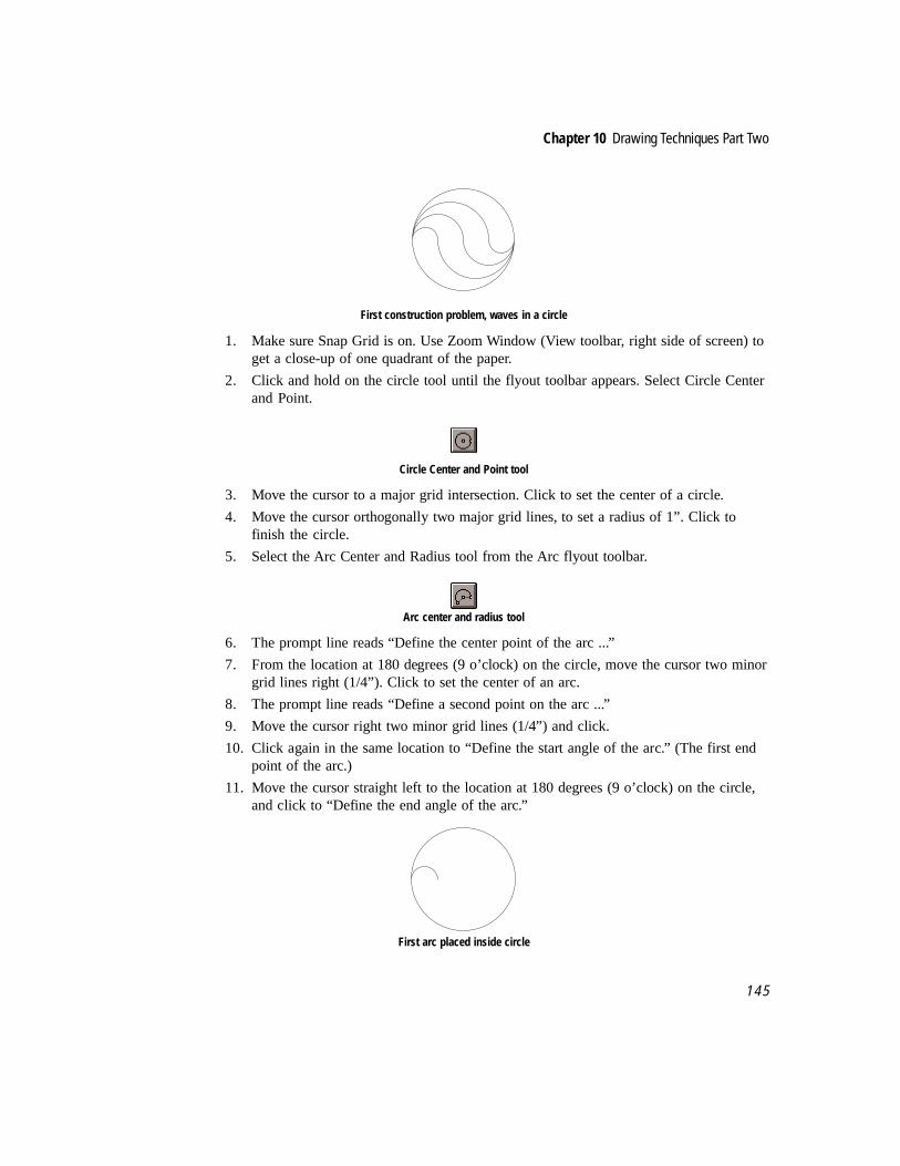
Chapter 10 Drawing Techniques Part Two
1 4 5
First construction problem, waves in a circle
1. Make sure Snap Grid is on. Use Zoom Window (View toolbar, right side of screen) toget a close-up of one quadrant of the paper.
2. Click and hold on the circle tool until the flyout toolbar appears. Select Circle Centerand Point.
Circle Center and Point tool
3. Move the cursor to a major grid intersection. Click to set the center of a circle.
4. Move the cursor orthogonally two major grid lines, to set a radius of 1”. Click tofinish the circle.
5. Select the Arc Center and Radius tool from the Arc flyout toolbar.
Arc center and radius tool
6. The prompt line reads “Define the center point of the arc ...”
7. From the location at 180 degrees (9 o’clock) on the circle, move the cursor two minorgrid lines right (1/4”). Click to set the center of an arc.
8. The prompt line reads “Define a second point on the arc ...”
9. Move the cursor right two minor grid lines (1/4”) and click.
10. Click again in the same location to “Define the start angle of the arc.” (The first endpoint of the arc.)
11. Move the cursor straight left to the location at 180 degrees (9 o’clock) on the circle,and click to “Define the end angle of the arc.”
First arc placed inside circle

The Complete Guide to TurboCAD for Windows V4
1 4 6
12. The arc command is still active.
13. Click on the right end point of the first arc to set the center of the next arc.
14. Move the cursor right 1/2” (4 minor grid lines) and click to “Define a second point onthe arc.”
15. Click at the same location a second time to “Define the start angle of the arc.”
16. Move the cursor to the left end point of the first arc and click to finish.
Two arcs inside circle
17. The arc command is still active.
18. Click on the grid intersection halfway between the right endpoints of the first twoarcs.
19. Move the cursor right 6 grid lines (3/4”) and click to set the radius of the new arc.
20. Click again at the same location to start the arc.
21. Move the cursor to the common left endpoints of the first two arcs and click to finish.
Three arcs inside circle
22. Click on the Select tool, and select the three arcs. This is easily done with oneselection rectangle if “Open Window Mode” is off in the local menu. Or, you mayselect the arcs with Menu: Edit|Select By|Entity Type and choose Arc.
23. From the menu, select Edit|Copy Entities|Radial.
24. Click on the right endpoint of the second arc (which is also the center point of thecircle) to define the center of the radial copy process.
25. The prompt says “Define the step angle.”
26. Press <Tab> repeatedly until the value in Sets is highlighted in the Edit Bar. Type 2.
27. Press <Tab> once to highlight the value in Angle. Type 180 and press <Enter>.
28. Click anywhere on screen to deselect the arcs.

Chapter 10 Drawing Techniques Part Two
1 4 7
Arcs copied using Radial copy
Concentric ArcUse the Concentric Arc tool when you need to draw a series of arcs that share a commoncenter point. Remember that arcs are always drawn counterclockwise in TurboCAD.
Second construction problem, braided arcs
1. Select the Single Line tool.
2. Using the intersection of two major grid lines as a center point, draw a symmetricalcross with each line extending 3/8" from the center.
Draw a symmetrical cross
3. In each quadrant formed by the lines of the cross, draw three lines each 3/8" long, asillustrated.

The Complete Guide to TurboCAD for Windows V4
1 4 8
NOTE: The Parallel Line tool or a copy tool could have been used in this part of the exercise,but the lines are so short and easy to draw with Snap to Grid that there is no time saved byswitching to another tool.
Draw three parallel lines in each quadrant
4. Select the Concentric Arc tool from the arc flyout toolbar.
5. The prompt reads “Define the center point of the arc ...”
6. Click on the right end point of the right line which formed the original cross, tochoose it as the center point for the arcs to be drawn.
7. The prompt reads “Define a second point ...”
8. Move the cursor one grid line down and click to set a point on the arc'scircumference.
9. The prompt reads “Define the start angle of the arc ...”
10. Click at the same location used to set the circumference.
11. Move the cursor straight up to draw an arc that ends on the line directly above thecenter point of the arc.
Use Concentric Arc to draw first arc
12. The Concentric Arc tool is still active, and will use the center previously defined todraw other arcs.
13. The prompt reads “Define a second point on the arc ...” Move the cursor 1/8" (onegrid line) below the start of the first arc. Click twice. The first click will set the radiusof the arc; the second click will start the arc.
14. Move the cursor 1/8" above the top end of the first arc, and click to set a second arc.
15. Move the cursor 1/8" below the start of the second arc and click twice.
16. Move the cursor 1/8" above the top end of the second arc and click to finish a thirdarc.
☞

Chapter 10 Drawing Techniques Part Two
1 4 9
Draw two more arcs
17. Click on the Select tool and select the three arcs.
18. From the Menu, select Edit|Copy Entities|Radial.
19. The prompt reads “Define the center of the copy process.” Click at the center of theoriginal cross.
20. Press the <Tab> key until Sets is highlighted in the Edit Bar. Type 4.
21. Press the <Tab> key to highlight Angle. Type 90, and press <Enter>.
Use Copy Radial to finish the drawing
Double Point ArcThe Double Point Arc tool lets you draw an arc by defining the endpoints of its diameter.
Third construction problem, camera lens shutter
1. Make sure Snap to Grid is on.
2. Select the Concentric Circle tool from the circle flyout toolbar.

The Complete Guide to TurboCAD for Windows V4
1 5 0
3. Move the cursor to the intersection of two major grid lines and click to set the centerof a circle.
4. Move left one minor grid line (1/8”) and click to finish a circle.
5. Move left one minor grid line (1/8”) and click to finish a second circle.
6. The circle tool is still active.
7. Move left to the second major grid line and click to create a third circle.
8. Click the Select tool.
9. Click on the Double Point Arc tool from the arc flyout toolbar.
Start by drawing three circles using the same center point
10. Move the cursor to the location at 180 degrees (9 o’clock) on the larger of the twointerior circles. Click to start an arc.
11. The prompt reads “Define a second point...” Move the cursor to the location at 0degrees (3 o’clock) on the largest circle and click to set the angle of the arc.
12. “Define the start angle of the arc.” Click again at the same location.
13. The prompt reads “Define the end angle of the arc.” Move the cursor right to thelocation at 180 degrees (9 o’clock) on the larger interior circle and click to finish thearc.
An arc has been added to the circles
14. Click on the Select tool and select the arc.
15. From the menu, select Edit|Copy Entities|Fit Radial Copy.
16. Click on the center of the three circles to “Define the center of the copy process.”
17. Press <Tab> repeatedly until the value in Sets is highlighted in the Edit Bar. Type 8.
18. Press <Tab> to highlight Angle in the Edit Bar. Type 360 and press <Enter>.
19. Click anywhere in the drawing area to deselect the original arc.

Chapter 10 Drawing Techniques Part Two
1 5 1
Use Fit Radial Copy to complete the construction problem
Start/Included/End (1-2-3) Arc
Fourth construction problem, flower pattern
1. Make sure Snap to Grid is active.
2. Select the Concentric Circle tool from the circle flyout toolbar.
3. Move the cursor to the intersection of two major grid lines and click to set the centerof a circle.
4. Move left two minor grid lines (1/4”) and click to finish the circle.
5. Move left two major grid lines (1”) and click to finish a second circle.
Start third construction problem by drawing two circles
6. Select Start/Included/End (1-2-3) from the arc flyout toolbar.
Start/Included/End (1-2-3) arc tool
7. Move the cursor to the location at 180 degrees on the larger circle. Click to start thearc.
8. “Define the middle point of the arc.” Locate the grid intersection four lines downfrom the top of the circle (90 degrees or 12 o’clock) and click to set the second pointof the arc.

The Complete Guide to TurboCAD for Windows V4
1 5 2
9. “Define the end point of the arc.” Move the cursor to the location at 0 degrees (3o’clock) on the larger circle and click to finish the arc.
An arc has been added to the circles
10. Select the arc.
11. From the menu, select Edit|Copy Entities|Mirror.
12. “Define the first point of the mirror.” Move the cursor to the location at 180 degrees(9 o’clock) on the larger circle and click to start the mirror axis line.
13. Move the cursor right to the location at 0 degrees (3 o’clock) and click to finish themirror, copying the arc.
Use Copy Entities|Mirror to copy the arc
14. Select both arcs.
15. From the menu, select Edit|Copy Entities|Fit Radial Copy.
16. Click on the center of the circle to set the center for the copying.
17. Press <Tab> until Sets is highlighted in the Edit Bar. Type 4.
18. Press <Tab> to highlight Angle in the Edit Bar. Type 360 and press <Enter>.
Fit Radial Copy is used to finish the construction problem

Chapter 10 Drawing Techniques Part Two
1 5 3
Drawing Arcs with the Edit BarSnaps and mouse entry were used to draw all the arcs so far. It is also possible to use theEdit Bar in various combinations with the mouse to draw arcs. To do so requires using theLock feature of the Edit bar. The small boxes to the left of the Radius and Circumf. fieldsare the Lock boxes. If a value is entered in one of the fields, and you activate the lock forthat field (by clicking on the box—an X appears), that value is set even if you move thecursor on screen. If you know specific values for the arc you need to draw, such as theradius, the circumference, or a starting or ending angle, you can enter the appropriate valuein the Edit Bar as part of drawing the arc. To avoid moving the mouse unnecessarily, pressthe <Tab> key to engage the Edit Bar. Each press of the <Tab> key moves one step throughthe Edit Bar fields. In the illustration below, the Edit Bar has been moved into the drawingarea, and a 2" radius has been specified by typing “2 in.” in the Radius field and clicking theLock Box. When the Edit Bar is floating in the drawing area, the name of the commandbeing used appears as the title of the box instead of “Edit Bar.”
Edit bar settings for drawing a 2" arc
Drawing Tangent Arcs, Lines and CirclesLines, arcs and circles may all be drawn tangent to arcs and circles. To draw a entity tangentto an arc or circle is to draw it so that the lines of the two objects come into contact but donot intersect. The two tools used to draw arcs tangent to other objects have already beenlisted. The other tangent tools are:

The Complete Guide to TurboCAD for Windows V4
1 5 4
Tool Action
Circle Tangent to Arc Draw a circle tangent to another circle or arc.
Circle Tangent to Line Draw a circle tangent to a line.
Tangent Arc Point Draw a line tangent to an arc or circle, touching the arc at the line’smidpoint.
Tangent To Arc Draw a line tangent to an arc or circle, with the line’s second endpoint touching the arc.
Tangent From Arc Draw a line tangent to an arc, with the line’s first endpoint touchingthe arc.
Tangent to 2 Arcs Draw a line tangent to two arcs, with each endpoint of the linetouching one of the arcs.
Complete the following construction problem to gain experience with some of the tangentcommands available in TurboCAD. The completed diagram is a cam assembly, a typicalmechanical engineering drawing. For this exercise you will shut off the screen grid and usea variety of snap commands.
Next construction problem, cam assembly
1. Click on No Snap in the Snaps Toolbar.
2. From the menu, select Tools|Grid and click the “Show Grid” box to shut off the grid.Click OK.
3. Select Circle Center and Point from the Circle flyout toolbar.
4. Click anywhere on the paper to start a circle.
5. Press <Tab> and type .295 for radius. Press <Enter>.
6. The circle command is still active. Right-click to summon the local menu. Click onlocal snap and select Arc Center.

Chapter 10 Drawing Techniques Part Two
1 5 5
7. Click on the circle.
8. Press <Tab> and type .64 for radius. Press <Enter>.
First two circles drawn using the Edit Bar
9. Select the Line tool.
10. Right-click to access the local menu. Click on local snap and select Arc Center. Clickon the larger circle.
11. Press <Tab>, type 2.45 for length; press <Tab>, type 340 (for angle) <Enter>.
12. Select the Circle Center and Point tool.
13. Right-click, local snap, Vertex.
14. Click on the right end of the line.
15. Press <Tab>, type .36 for radius. Press <Enter>.
A third circle has been placed
16. Click on Tangent to 2 Arcs in the Line flyout toolbar.
17. The prompt reads “Pick an arc.” Click on the top side of the larger left circle.
18. “Choose the tangent.” Click on the top side of the circle on the right.
The second line is tangent to two circles

The Complete Guide to TurboCAD for Windows V4
1 5 6
19. The Tangent to 2 Arcs command is still active.
20. Click on the bottom side of the larger left circle.
21. Click on the bottom side of the circle on the right.
A second tangent line is added to the bottom
22. Click on the Line tool.
23. Select Vertex Snap from the Snap toolbar.
24. Click on the left endpoint of the bottom tangent line.
25. Click on the left endpoint of the top tangent line.
26. Repeat the process for the circle on the right side of the diagram.
Lines connect the ends of the tangent lines
27. Click on the Select tool.
28. From the menu, select Modify|Object Trim.
29. Click on the left (nearly vertical) line to select it as the cutting edge.
30. Move the cursor right and click on the larger circle.
31. Press <Esc> to deselect the cutting edge. The Object Trim tool is still active.
32. Click on the right (nearly vertical) line to select it as the cutting edge.
33. Move the cursor a little to the left and click on the circle.
34. Click on the Select tool.

Chapter 10 Drawing Techniques Part Two
1 5 7
Object Trim was used to remove a half circle from each side
35. Use the Select tool and the <Delete> key to delete the two cutting edges and the linerunning through the center of the diagram.
Three interior straight lines removed
36. Select the Tangent to Arc tool from the Circle flyout toolbar.
37. Click on the top of the largest arc, left side of the diagram.
38. Press <Tab> and set the Radius as .31. Press <Enter>.
The new circle is tangent to the left side of the existing arc
39. Click on Snap Arc Center in the Snaps toolbar.
40. Select Circle Center and Point from the Circle flyout toolbar.
41. Click on the last circle placed.
42. Press <Tab>, type .14, press <Enter>.

The Complete Guide to TurboCAD for Windows V4
1 5 8
A new circle, placed inside the previous one
43. Click on Quadrant Snap in the Snaps toolbar. Deselect any other active snap.
44. Select the Line tool. Click on the larger of the two upper circles at 180 degrees (9o’clock) and at 0 degrees (3 o’clock).
Use Quadrant Snap to add the new line
45. Click on the intersection of the left bisecting line and the small circle.
46. Click on Ortho Mode in the Snaps toolbar. All other snaps will be shut off.
47. Move the cursor straight up. Press <Tab>, type .45 <Enter>.
48. Repeat the process on the right side (Quadrant Snap, start line, Ortho mode, setdistance).

Chapter 10 Drawing Techniques Part Two
1 5 9
Use Quadrant Snap and Ortho Mode to draw two new lines
49. Click on the Select tool.
50. From the menu select Modify|Object Trim.
51. Click on the line bisecting the top circle as the cutting edge.
52. Click on the top side of the inner circle.
Use Object Trim to remove the top of the upper inner circle
53. Click on the Select tool.
54. Select and delete the bisecting line used as the cutting edge.
55. Select the Line tool and the Vertex Snap.
56. Click on the endpoints of the two lines extending vertically, to close the gap.
Close the gap on top with a single line

The Complete Guide to TurboCAD for Windows V4
1 6 0
Using EllipsesThe ellipse is a common feature in both architectural and engineering applications.TurboCAD offers six elliptical tools, three for complete ellipses, and three for elliptical arcs.To draw a true ellipse on paper, you need a string tied at the ends to form a loop, and twopins. Stick the two pins into the paper and lay the loop around them. Draw with the pencil,using the string as a guide. Keep the string taut, so that every point on the line you draw isthe same distance from both pins. The finished product is an ellipse. The definition of anellipse is “the path of a point that moves so that the sum of its distances from two fixedpoints is constant.”
The various ellipse tools define a bounding rectangle. The length and width of the rectanglecorrespond to the length and width of the ellipse. If you know the length values for the twoaxis that define the ellipse, type them in the Edit Bar.
When you need to be exact, placing an ellipse correctly is much easier if you draw lines orplace points beforehand, then snap to these locations to place the axis points of the ellipse.Or, snap to existing objects in the drawing.
Tool Action
Elliptical Arc Draw an elliptical arc by defining its bounding rectangle.
Rotated Elliptical Arc Draw an elliptical arc rotated at any angle.
Fixed Ratio El. Arc Draw an elliptical arc by defining a ratio and identifying either axis.
Ellipse Draw an ellipse by defining its bounding rectangle.
Rotated Ellipse Draw an ellipse rotated at any angle.
Fixed Ratio Ellipse Draw an ellipse by defining a ratio and identifying either axis.
Draw a Standard Ellipse
1. Activate the Ellipse tool from the circle flyout toolbar.
Ellipse tool
2. Define the first point or corner of the bounding rectangle, then do one of thefollowing:
• Move the cursor and click to define the diagonally opposed corner of the boundingrectangle;
• Specify the lengths of the ellipse’s major and minor axes in the Edit Bar, then press<Enter>.

Chapter 10 Drawing Techniques Part Two
1 6 1
Draw a Rotated Ellipse
1. Activate the Rotated Ellipse tool from the circle flyout toolbar.
Rotated ellipse tool
2. Click to define the center point of the ellipse.
3. Click to define a point, specifying an angle and distance from the center point. Thiscreates an axis from the defined point, through the center point, to an opposite pointthe same distance from the center point. You can view this axis on the screen as youadjust the position of the point using the mouse or Coordinate Fields.
4. Define a second point to specify the length of the opposite axis. This axis will beperpendicular to the first axis.
Alternatively, you can define the center point of the ellipse, specify the length and angle ofthe major axis and the length of the minor axis in the Edit Bar, then press <Enter>.
Draw an Elliptical Arc
The lengths of the major and minor axis of the elliptical arc are determined by the lengthsof the sides of the bounding rectangle. The axes of the arc will be orthogonal; however, youcan rotate the arc after you have created it using the editing tools.
1. Activate the Elliptical Arc tool from the arc flyout toolbar.
Elliptical arc tool
2. Define a point for the first corner of the bounding rectangle.
3. Define a point for the diagonally opposite corner of the bounding rectangle.TurboCAD draws an ellipse bounded by the rectangle that you have defined. A dottedline appears, extending from the center point of the ellipse to the cursor.
4. Move the cursor to change the dotted line to the angle at which you want the arc tostart, then click to set the arc’s starting angle.
5. Move the cursor counterclockwise to draw the arc, then click the mouse button todefine the ending angle.
Alternatively, you can define the starting point of the elliptical arc, then specify its majorand minor axes and starting and ending angles in the Edit Bar. You can also combine use ofthe mouse and Edit Bar.

The Complete Guide to TurboCAD for Windows V4
1 6 2
Draw an Elliptical Rotated Arc
1. Activate the Rotated Elliptical Arc tool in the Arc flyout toolbar.
Rotated elliptical tool
2. Define the center point of the arc.
3. Define a point to specify an angle and distance from the center point. This creates anaxis from the defined point, through the center point, to an opposite point the samedistance from the center point. This is the major axis of the elliptical arc.
4. Define a third point to specify the length of the minor axis (perpendicular to themajor axis). TurboCAD draws an ellipse with the specified major and minor axes. Adotted line appears, extending from the center point of the ellipse to the cursor.
5. Move the cursor to change the dotted line to the angle at which you want the arc tostart, then click to set the arc’s starting angle.
6. Move the cursor counterclockwise to draw the arc, then click the mouse button todefine the ending angle.
Curve ToolsTurboCAD offers three curve tools, each with special properties.
The Spline is a continuous curve that connects from point to point as placed in the drawing.The Spline in manual drafting is a long, flat pliable strip of wood, metal or plastic used todraw curves. The advantage of the spline in manual drafting (and which carries over in thetechnology of the Spline command in TurboCAD) is that by tracing along the spline thecurve is created as one continuous line, not a series of curved segments with awkwardchanges of direction connecting each curve. The final product is a smooth, continuouscurve, not a series of fitted arcs or clipped circles.
While the Spline curve is best for smooth, regular curved lines, the Bezier curve tool isbetter for drawing irregularly shaped curved lines. Bezier curves are named for Frenchengineer Pierre Bezier, who developed a curve-generation algorithm for car designers atRenault. Bezier curves have become standard in CAD programs in recent years because theyare fast and the procedures used in drawing them become fairly predictable after one workswith them for a while.
Bezier curves are defined by a set of control points, intermediate points placed in thedrawing in addition to the curve and the points that define the position of the curved line.The control points act as magnets, affecting the shape of the curve depending on theirlocation.
The Sketch tool is used for freehand drawing. Whether the lines drawn are elegant or ugly iscompletely up to the artist.

Chapter 10 Drawing Techniques Part Two
1 6 3
Tool Action
Spline Draw a continuous curve that connects a series of points.
Bezier Draw a curve that connects two endpoints; the curve gravitatestoward control points along its path.
Sketch Freehand multiline drawn with mouse.
Curve PropertiesCurves have special properties that can be set in the Curve property sheet of the Propertiesdialog. This property sheet lets you show or hide the frame of a Bezier or Spline curve,transform a Bezier curve into a Spline curve or vice versa. You can access the properties of acurve by double-clicking on it with the Select tool, or by selecting the curve and thenchoosing Menu: Format|Properties. The properties for curves are accessed via right-clickingthe curve's button on the toolbar.
To close a Bezier or Spline curve, right-click on the local menu and select Close. To endeither curve without forming a closed loop, right-click on the local menu and select Finish.
Using Curves to Create Parabolas and SpiralsCertain curves have special properties in engineering, architecture and in nature. Theparabola, for example, defines a comet’s path around the sun, and is used to designreflecting surfaces, road sections and arches. The spiral is found throughout nature in suchthings as DNA, the chambered nautilus, the abalone, the spider web, and the shape of somegalaxies.
Follow the steps below to construct a parabola and a logarithmic spiral. Both objects requirethat you draw construction aids to identify points along each curve. Instead of detailedsteps, the instructions for these two exercises give you guidelines to follow, along withillustrations showing the details.
Construct a Parabola
1. Using Snap to Grid, construct a rectangle four units wide and eight units deep. UsePoints to mark the units along the top, left and bottom as illustrated.

The Complete Guide to TurboCAD for Windows V4
1 6 4
Use the grid to construct a rectangle and place points
2. Use straight lines to connect the points along the top and the bottom with themidpoint of the right side of the rectangle. Draw straight lines from the points alongthe right side, forming intersections as illustrated.
3. Use the Bezier curve to draw a shape connecting the points as identified. Shut offGrid Snap, and select Intersection Snap from the Snap Toolbar. To finish the curve,right-click and select Finish from the local menu. The finished shape is a parabola.
Construction lines added to rectangle; squares mark points to place curve
4. Erase the construction aids.

Chapter 10 Drawing Techniques Part Two
1 6 5
Parabola after all construction aids removed
Construct a Logarithmic Spiral
1. From the menu, select Options|Grid. Change the grid type to Polar. Set Angular to 15and Radial to .125 in.
Settings for Grid tab
2. Click the Advanced Grid tab. Set the origin for both X and Y to 5 in.; set theDivisions for both Minor A and Minor R to 1. Click OK.

The Complete Guide to TurboCAD for Windows V4
1 6 6
Settings for the Advanced Grid tab
3. Click on Snap to Grid in the Snaps toolbar. Select the Spline curve from the Curveflyout toolbar.
4. Use Zoom Window to get a close-up view of the center section of the polar grid.Click on the center point to start the spiral. Move the cursor up along the Angle Gridline pointing straight up (12 ’clock or 90 degrees) until you reach the first intersectionwith a Radial grid line. Then move along the first Radial grid line until you intersectthe next Angular grid line. Click to set a point on the spiral. Continue to set pointusing this one-out, one-over pattern. Use the scroll bars and/or the zoom commandsto adjust the view as you place the curve. To finish, right-click and select Finish fromthe local menu.
The first few segments of a spiral

Chapter 10 Drawing Techniques Part Two
1 6 7
Node EditingTurboCAD offers a special set of editing capabilities for entities called Node Edit mode. InNode Edit mode you can reshape entities by directly manipulating particular points callednodes.
• Add, delete, and move nodes on entities composed of line segments (including lines,double lines, polygons).
• Divide line segments into any number of subsegments of equal length.
• Break polygons, making them into multilines.
• Close multilines, making them into polygons.
• Close the endpoints of double lines.
• Reshape Bezier and spline curves by adding, deleting, and moving nodes on the linesegments that form the curve’s frame.
• Change the radius of circles and circular arcs.
• Change the major and minor axes of ellipses and elliptical arcs.
• Change the start and end angles of circles, ellipses, and arcs.
• Close arcs, making them into circles.
• Divide circles, arcs, and ellipses into arc segments of equal angular length.
To activate Node Edit mode, click on the Node Edit tool in the Insert Entity toolbar, at thetop of the screen. When you select an object with the Node Edit tool, the appearance of theselection is different than when the Select tool is used. Instead of a selection box withhandles, you will see highlighted objects with nodes displayed as blue rectangles. Thenumber and placement of the nodes depends on the type of object selected.
Selected objects in Node Edit mode
You can only edit one entity at a time in Node Edit mode. You cannot use this mode to workwith multiple selected entities or groups. To edit the nodes of an entity that is in a group,first select the group, then break it into its component entities using the Menu:Format|Explode command. If the entity is part of a nested group, you may have to useExplode more than once.

The Complete Guide to TurboCAD for Windows V4
1 6 8
On Your OwnExperiment with Node Edit on your own. Draw a variety of entities, then use Node Edit oneach entity to reshape or break entities. If you have not already encountered the otherexercises in this book that use Node Edit, check the Index to find them.
To delete a node, select the entity and enter Node Edit mode. Hold down the <Ctrl> keywhile placing the mouse cursor over the node you wish to delete. When you are in thecorrect position, the cursor will change to an icon showing a node being thrown into a trashcan. Click to delete the node. If you delete a node on a rectangle, for example, itimmediately becomes a triangle. It is not possible to use node delete to remove a node froma single line segment or to convert a polygon to a single line.

1 1Dimensioning
Placing Exact Measurements
As explained in Chapter Eight, text in a CAD drawing bridges the worlds of verbal andvisual expression. Labeling a TurboCAD drawing gives the “reader” a frame of reference tohelp interpret drawings.
Often CAD drawings are created only to express a design idea, so informally labeling partsof the drawing is enough. But many CAD drawings are used as the primary constructionplans. These drawings need more than simple labels. Whoever uses the drawing needs toknow the exact dimensions of objects in the drawing.
TurboCAD supports automatic dimensioning, a series of commands that let you measure thedistance between two points, draw reference lines, measure lengths and angles, and printmeasurements on the drawing near the measured objects. By dimensioning, we refer to theact of placing the measurements or other important information about an object into thedrawing.
By default, dimensions in TurboCAD are associative. This means that if a dimensionedobject changes in size, the dimensioning already on the screen will automatically update toaccurately display the new length, angle, etc. If you don’t want associativity toautomatically update dimensions, this feature can be turned off in the DimensioningProperty Sheet. To check if a dimension line is associated with an entity, select the entity.Any dimensions associated with it will be colored blue.
Using dimensions in your designs makes the drawings easy to interpret. But the process ofplacing dimensions in a drawing can be confusing to the new user because of the largenumber of variations available in the dimensioning commands. But once you know a fewrules of thumb, the number of decisions quickly dwindle down. This chapter will providereference material on dimensions, exercises to guide you through using dimensions for the

The Complete Guide to TurboCAD for Windows V4
1 7 0
first time, and will offer a few guidelines for knowing when and how to place dimensions inyour drawings.
Elements of DimensioningWhen TurboCAD dimensions an object, it calculates the object’s length, angle, diameter, orradius (as requested), draws two lines to show the distance, draws a line or arc with arrowson each end between these two lines, and displays the measurement. These pieces can bedivided into three basic components:
• The dimension lines, with arrows pointing to either end of the dimension.
• Extension lines, which connect the dimension line to the object being measured.
• Dimension text, normally displaying the distance being measured in World units.
1.5 in
Parts of a dimension
Extension lines have optional line segments that continue the extension outward beyond thedimension line (extensions to the extension). Extension lines are also called witness lines bysome professions.
A dimension can have interior dimension lines, as shown in the preceding figure, or twoexterior dimension lines. Exterior dimension lines can be supplemented with an optionalinterior line.
Format Property SheetsThree Format Property Sheets control the shape of dimension arrows and the position of textrelative to the dimension line. You can summon the dimension format property sheets in oneof two ways: Either Right-Click the dimension tool on the Insert Entity toolbar; or, if thedimension tool is active, select Menu: Format|Properties.
Dimension text
Dimension line
Extension line

Chapter 11 Dimensioning
1 7 1
Dimension format properties sheet
Dimension Format Property SheetThe Format Properties sheet provides controls for basic dimensioning features, including theshape of arrowheads, the size and appearance of text, and the positioning of dimensioninglines.
Arrowheads
1st and 2nd. Click in these drop-down boxes to choose dimension arrow shapes. Thearrowheads can have angles of 15, 30 or 45 degrees; they can be filled, open, or closed. Ifyou like, you can choose None (no arrowhead at all), Tick (a simple angled line), HollowDot or Solid Dot.
Size. Click the Size field to choose a size for the length of the arrowhead, or type in acustom size. (How to determine the correct size for an arrowhead is discussed later in thechapter.)
Tick Extension. If you set the arrowhead to Tick in the 1st and 2nd boxes, use this field tospecify the length of each tick’s extension line.
2
2
2 2
2
2
Dimension arrow shapes

The Complete Guide to TurboCAD for Windows V4
1 7 2
Text Position
Font. Use the Font text box to choose a TrueType font for the dimension text. All TrueTypefonts installed on your computer will be available.
Height. Click this text box to choose a text height, or type in a custom height. You can setthe height in either World or Paper units, to match your current working mode.
Position. Choose Outside if you want the text placed outside of the dimension line; chooseAbove if you want the text “above” the dimension line (“above” is relative to the orientationof the text, not relative to your screen); or choose On Line if you want to place the textdirectly on the dimension line. The position can be manually adjusted (see the next control).
On Line Adjustment. Type a number into this text box to specify the distance of the textabove or below the dimension line. A value of zero (the default value) will place the text onthe same level as the dimension line. Higher values move the text above the line (“above” isrelative to the orientation of the text); lower (negative) values move the text below the line.
Force Text Horizontal. Check this box if you want the dimension text to be horizontal nomatter how the dimension is rotated.
Force Dimension Text Inside Extension Lines. Click this box if you want to keep dimensiontext between the extension lines, regardless of the distance between the extension lines. Ifyou leave this box unchecked, TurboCAD will decide whether to place dimension textinside or outside the extension lines.
1
20.5
2.24
1.5
Various positions for dimension text
Advanced Format Property SheetThe Advanced Format Property Sheet controls a variety of more specialized options for thepositioning of dimension lines. If you are overwhelmed by the number of options and detailsavailable, you can bypass this property sheet and the next one (Advanced Text) until you aremore comfortable with basic dimensioning operations.
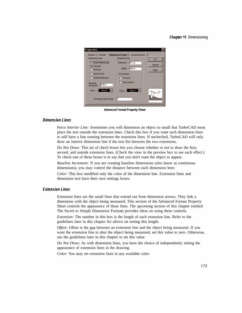
Chapter 11 Dimensioning
1 7 3
Advanced Format Property Sheet
Dimension Lines
Force Interior Line: Sometimes you will dimension an object so small that TurboCAD mustplace the text outside the extension lines. Check this box if you want such dimension linesto still have a line running between the extension lines. If unchecked, TurboCAD will onlydraw an interior dimension line if the text fits between the two extensions.
Do Not Draw: This set of check boxes lets you choose whether or not to draw the first,second, and outside extension lines. (Check the view in the preview box to see each effect.)To check one of these boxes is to say that you don't want the object to appear.
Baseline Increment: If you are creating baseline dimensions (also know as continuousdimensions), you may control the distance between each dimension here.
Color: This box modified only the color of the dimension line. Extension lines anddimension text have their own settings boxes.
Extension Lines
Extension lines are the small lines that extend out from dimension arrows. They link adimension with the object being measured. This section of the Advanced Format PropertySheet controls the appearance of these lines. The upcoming section of this chapter entitledThe Secret to Simple Dimension Formats provides ideas on using these controls.
Extension: The number in this box is the length of each extension line. Refer to theguidelines later in this chapter for advice on setting this length.
Offset: Offset is the gap between an extension line and the object being measured. If youwant the extension line to abut the object being measured, set this value to zero. Otherwise,use the guidelines later in this chapter to set this value.
Do Not Draw: As with dimension lines, you have the choice of independently setting theappearance of extension lines in the drawing.
Color: You may set extension lines to any available color.

The Complete Guide to TurboCAD for Windows V4
1 7 4
Dimension Size Scale
In a large and detailed drawing, you may want some dimensions to stand out more thanothers. The best way to do this is to use two sizes of dimension lines. But changing all thesettings that control the size of a dimension line would be a tedious task. Instead, use theDimension Size Scale text box to set the scale size of dimensions. For your most importantdimensions lines, set this value to 1. For other dimensions, set this value to somethingsmaller, like .75, which would cause subsequent dimensions to be place at 75% of the sizeslisted in the various dimension settings.
Dimensioning ToolsEleven dimensioning tools are available in the flyout toolbar from the Insert Entity toolbar,or from the menu (Insert|Dimension|tool). The tools, and their actions, are:
Tool Action
Horizontal Dimension Measure and display the horizontal distance between two points orthe horizontal length of a specific object.
Vertical Dimension Measure and display the vertical distance between two points or thevertical length of a specific object.
Parallel Dimension Measure and display the absolute distance between two points or theabsolute distance of a specific object.
Rotated Dimension Measure and display the absolute distance of an object, but rotatethe display to the same angle as the object being measured.
Datum Dimension Display a progression of measurements connected to angled leaderlines, generally along a horizontal or vertical axis.
Baseline Dimension Display a progression of parallel measurements that share acommon baseline (starting point).
Continuous Dimension Display a progression of parallel measurements, each newmeasurement starting where the previous measurement ended.
Angular Dimension Measure the angle formed by two lines, by points on the perimeterof a circle or arc, or the angle formed by any two points relative to adefined vertex.
Radius Dimension Measure and display the radius of an arc or circle.
Diameter Dimension Measure and display the diameter of an arc or circle.
Leader Dimension Draw an arrow and a line and add text as a label.

Chapter 11 Dimensioning
1 7 5
Linear Dimensioning MethodsThe first seven dimension methods listed above are collectively known as linear dimensions.They measure distances along a line (real or imagined). But to understand how thesemethods differ, we need to consider only three for the moment: Horizontal, Vertical andParallel Dimensioning . How these three measure lengths is very different one from theother.
Horizontal Dimension will display only the horizontal distance of an entity, or thehorizontal distance between two points that you identify. If the object is not parallel to thehorizon, the distance being measured is not the same as the actual length of the object.Complete the following exercise to gain experience with this.
Practice Horizontal Dimensioning
1. Launch TurboCAD; accept the Normal template.
2. Use Snap to Grid and Irregular Polygon (in the Single Line flyout toolbar) to drawthe eight-sided irregular polygon shown below. The exact length of each side is notcrucial.
#1
#2
#3
#4
Draw an eight-sided polygon to start the exercise
3. Select the Horizontal Dimensioning tool from the Dimensioning flyout toolbar in theEntity Insert toolbar.
Horizontal dimensioning tool
4. Deselect Snap to Grid; select Vertex Snap.

The Complete Guide to TurboCAD for Windows V4
1 7 6
5. Click on the upper end of line Number 1.
6. Click on the lower end of the same line.
7. Right-click for the local menu. Select Local Snap|No Snap.
8. Click anywhere to place the dimension line.
0
Horizontal dimension of a vertical distance
TurboCAD shows “0 in.” because the Horizontal Dimensioning tool can only calculatehorizontal distances. This line has no horizontal distance, it only has vertical distance.
Go ahead now and use Horizontal Dimensioning the way it was intended.
1. The Horizontal Dimensioning tool is still active. Click on the left endpoint of lineNumber 2.
2. Click on the right endpoint of the same line.
3. Right-click, and select Local Snap|No Snap. Move the dimension line where youplease, and click to place it in the drawing.
0
1.5
New dimension line also measures a horizontal distance
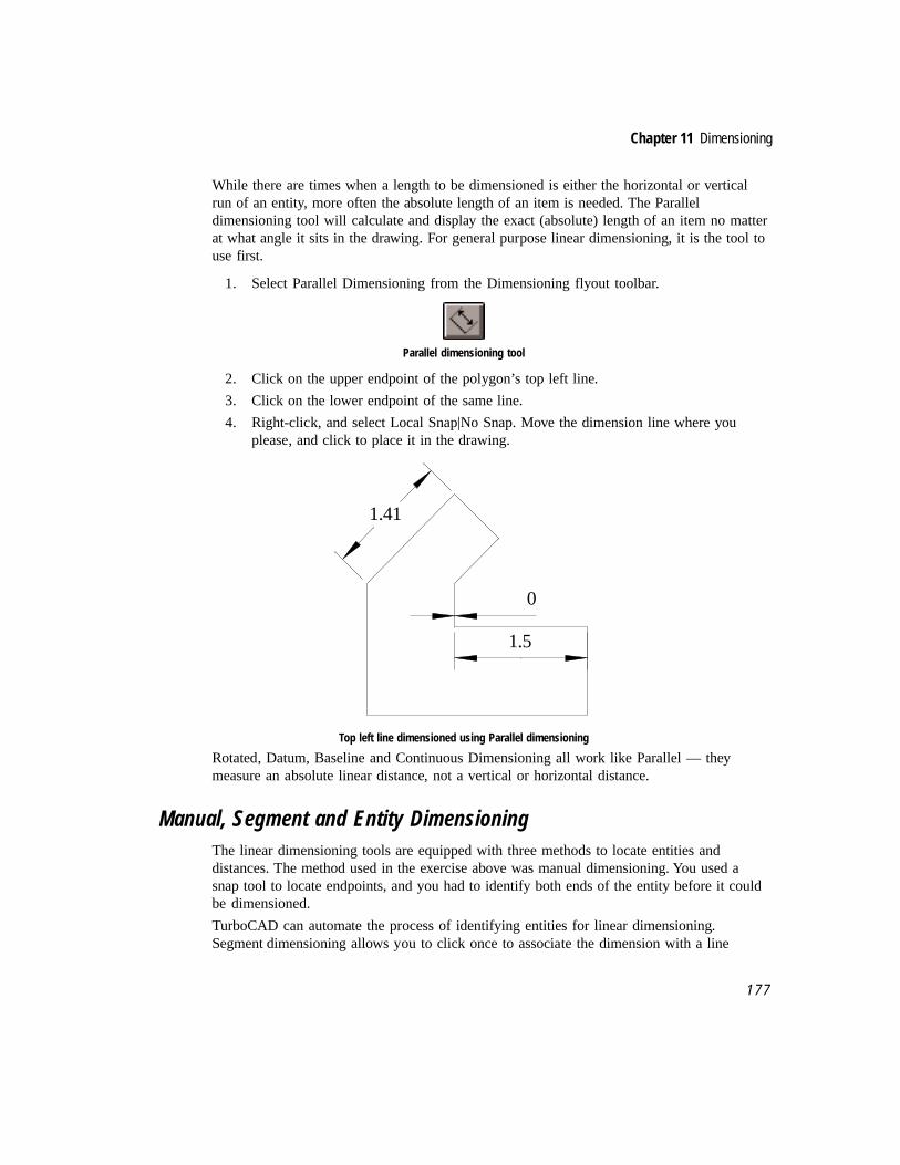
Chapter 11 Dimensioning
1 7 7
While there are times when a length to be dimensioned is either the horizontal or verticalrun of an entity, more often the absolute length of an item is needed. The Paralleldimensioning tool will calculate and display the exact (absolute) length of an item no matterat what angle it sits in the drawing. For general purpose linear dimensioning, it is the tool touse first.
1. Select Parallel Dimensioning from the Dimensioning flyout toolbar.
Parallel dimensioning tool
2. Click on the upper endpoint of the polygon’s top left line.
3. Click on the lower endpoint of the same line.
4. Right-click, and select Local Snap|No Snap. Move the dimension line where youplease, and click to place it in the drawing.
0
1.5
1.41
Top left line dimensioned using Parallel dimensioning
Rotated, Datum, Baseline and Continuous Dimensioning all work like Parallel — theymeasure an absolute linear distance, not a vertical or horizontal distance.
Manual, Segment and Entity DimensioningThe linear dimensioning tools are equipped with three methods to locate entities anddistances. The method used in the exercise above was manual dimensioning. You used asnap tool to locate endpoints, and you had to identify both ends of the entity before it couldbe dimensioned.
TurboCAD can automate the process of identifying entities for linear dimensioning.Segment dimensioning allows you to click once to associate the dimension with a line

The Complete Guide to TurboCAD for Windows V4
1 7 8
segment. Entity dimensioning allows you to click once to associate the dimension with anentire entity (such as a multiline, or a group). Segment and Entity are available as options inthe local menu when a linear dimensioning command is active. Complete the exercise belowto gain experience using both methods.
Segment Dimensioning
1. Change to the Select tool and delete the previous dimension lines.
2. Select Parallel Dimensioning.
Parallel Dimensioning tool button
3. Right-click and select Segment Dimensioning. Set snaps to No Snap using the Snaptoolbar.
4. Click anywhere on line Number 4 and place the dimension line nearby. Click tofinish.
0.71
Parallel dimensioning using the Segment dimensioning option
Entity Dimensioning
1. The Parallel Dimensioning tool should still be active.
2. Right-click and select Entity Dimensioning (this will automatically deselect SegmentDimensioning).
3. Click anywhere on the same line (line Number 4) as selected just above.

Chapter 11 Dimensioning
1 7 9
4. Move the cursor up and to the left from the line. Notice the readout on the dimensionline (even though it has not be placed in the drawing, the dimensioning text should bevisible).
5. Now move the cursor down and to the right from the line. Notice how the readoutchanges.
6. Move the cursor down and to the right to the location you choose for the dimension line.
0.71
2.92
Entity dimensioning shows the width of the entire object
When Entity Dimensioning is active, selecting any individual line in a polygon or grouponly shows the tool at what angle it is dimensioning the entire object. As you moved thecursor around the screen before placing the dimension line, the angle changed, so the linearreadout changed as well.
Used appropriately, Segment and Entity Dimensioning can make quick work of complexdimensioning jobs.
NOTE: When Segment or Entity Dimensioning is turned on, the dimensioning method staysactive either until the other method is selected, or until you click on the name of the method inthe local menu to deselect it.
Angular DimensioningThe Angular Dimensioning tool is used to measure angles. With it you can dimension:
• The angle formed by any two lines.
• The angle of an arc.
• The angle formed by any two points on the perimeter of a circle.
• A freeform angle that you create by defining a vertex node and two points.
☞
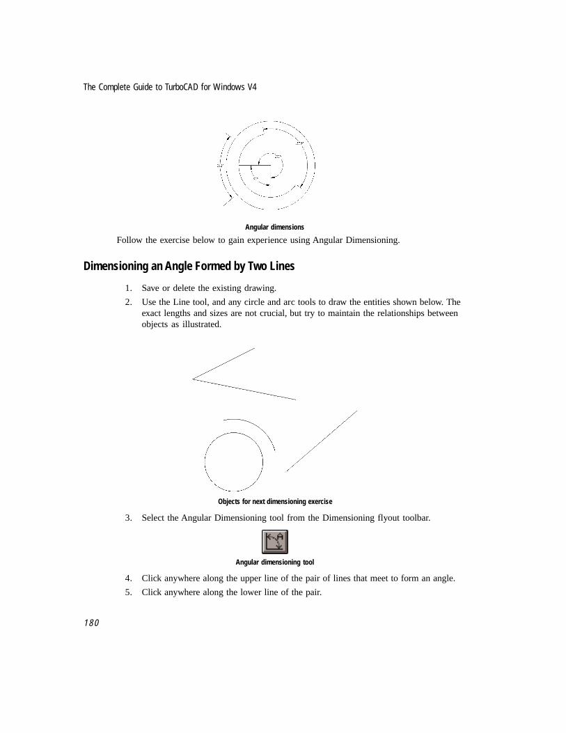
The Complete Guide to TurboCAD for Windows V4
1 8 0
Angular dimensions
Follow the exercise below to gain experience using Angular Dimensioning.
Dimensioning an Angle Formed by Two Lines
1. Save or delete the existing drawing.
2. Use the Line tool, and any circle and arc tools to draw the entities shown below. Theexact lengths and sizes are not crucial, but try to maintain the relationships betweenobjects as illustrated.
Objects for next dimensioning exercise
3. Select the Angular Dimensioning tool from the Dimensioning flyout toolbar.
Angular dimensioning tool
4. Click anywhere along the upper line of the pair of lines that meet to form an angle.
5. Click anywhere along the lower line of the pair.

Chapter 11 Dimensioning
1 8 1
6. Move the cursor inside the angle, then outside. Notice how the dimension changesbetween measuring the inside angle and the outside angle.
7. Move the cursor inside the angle, select No Snap from the local menu, and place thedimension where you please.
Dimensioning the angle of two lines
Dimensioning Angles on Circles
In the next exercise you will use other entities in the drawing to identify the portion of thecircle to be dimensioned.
1. The Angular Dimension tool is still active.
2. Click anywhere on the circle. A rubberband line will appear, extending from thecenter of the circle to the mouse cursor.
3. The prompt line reads “Define first angle endpoint.”
4. Select Snap Vertex from the Snaps menu.
5. Click where the two lines at the top of the drawing meet to form an angle.
6. The prompt now reads “Define second angle endpoint.”
7. Move the cursor to the lower right portion of the screen and click on the lowerendpoint of the single line.
8. Move the cursor inside the circle, then outside. Notice how the angular measurementchanges as a result.
9. Select No Snap (from either the local menu or the Snaps toolbar), and place thedimension inside the circle.

The Complete Guide to TurboCAD for Windows V4
1 8 2
Dimensioning the circle
Dimensioning Angles on Arcs
1. The Angular Dimensioning tool is still active. Click on the arc located just above thecircle. Adjust the snaps as necessary.
2. Move the cursor above and below the arc. Move the cursor all the way below thecircle and watch the changes in the measurement.
3. Move the cursor above the arc and place the dimension.
Dimensioning the arc

Chapter 11 Dimensioning
1 8 3
When you use the Angular Dimension tool on an arc, TurboCAD automatically dimensionsthe angle formed by the endpoints of the arc (the angle that would be formed by linesextending from the ends of the arc to the center). If you want to dimension the angle formedby any other two points on the perimeter of the arc, you can employ the Angle Nodetechnique described in the next section, using snap modes to define points at the center andon the perimeter of the arc.
Dimensioning Freeform AnglesYou can dimension the angle formed by any two points in the drawing space relative to adefined endpoint (vertex), using the Angle Node option in the local menu.
1. Select and delete each of the existing dimension lines. Be careful to leave the entities.
2. Select the Angular Dimensioning tool.
3. Right-click for local menu and select Angle Node.
4. Select Snap Vertex from the Snaps toolbar (if not already active).
5. Click on the upper endpoint of the single line, to identify it as the first of three pointsto define an angle.
6. The prompt reads “Define first angle endpoint.”
7. Click on the lower end of the single line.
8. The prompt reads “Define second angle endpoint.”
9. Click on the lower endpoint of the nearby arc.
10. Move the cursor above and below the single line, and notice how the dimensionreadout changes.
11. Place the dimension near the bottom of the single line by the arc, adjusting snaps asnecessary.
The angle framed by the line and the arc have been dimensioned

The Complete Guide to TurboCAD for Windows V4
1 8 4
Radius and Diameter DimensioningThe Radius and Diameter Dimensioning tools work on both arcs and circles. The techniquefor use is identical:
• Activate the tool.
• Click on the arc or circle.
• Click again to place the dimension.
Follow the steps below to practice using each tool.
Dimensioning the Radius of an Arc
1. Save your previous work and start a new drawing or delete all entities and dimensionlines, to clear the screen.
2. Draw a circle and an arc, as illustrated below.
Arc and circle for Radial dimension exercise
3. Select the Radius Dimensioning tool from the Dimensioning flyout toolbar.
Radius dimensioning tool
4. Click No Snap in the Snaps toolbar, then click anywhere along the arc.
5. Move the cursor until the dimension line is in a position you like, then click to placethe dimension.

Chapter 11 Dimensioning
1 8 5
R1.8
Radial dimension of arc
Dimension the Diameter of a Circle
1. Select Diameter Dimension from the Dimensioning flyout toolbar.
Diameter dimensioning tool
2. Click anywhere along the circumference of the circle.
3. Move the cursor until the dimension line is in a position you like, then click to placethe dimension.
R1.8
Ø2
Diameter dimension placed on circle

The Complete Guide to TurboCAD for Windows V4
1 8 6
Leader DimensionsUse Leaders to place a note about an object into the drawing. Each Leader has an arrow anda line pointing from the note to the object. The Leader tool is similar to the Multiline toolsin that it can contain an arbitrary number of connected line segments, oriented to any angle.
Leader dimension
The Leader has four parts:
• The arrow, which points to the object.
• The line, which can be more than one segment if necessary
• The shoulder, which serves as a base for the text.
• The text.
Follow the exercise below to become familiar with the Leader tool.
Label the Circle with a Leader
1. Select Leader from the Dimensioning flyout toolbar.
Leader tool
2. Make sure No Snap is active.
3. Click along the top edge of the circle.
4. The prompt reads “Define the next point of the string.”
5. Press <Tab> to highlight the Text field in the Edit Toolbar.
6. Type “Circle #1”
7. Click to return control to the cursor. Move the cursor until you find a position youlike for the leader line.
8. Right-click and select Finish from the local menu.

Chapter 11 Dimensioning
1 8 7
R1.8
Ø2
Circle #1
Leader used to label circle
In addition to placing the leader using the Finish command in the local menu, you candouble-click in the drawing. A single-click causes a new section of the leader line to bedrawn.
Professional StandardsArchitecture and engineering, the two professions most commonly associated with drafting,have each developed guidelines for the appearance of drawings. If you need to have yourdrawings conform to either set of professional guidelines, you will have fewer decisions tomake about dimension settings.
The guidelines that follow are generalizations on how professionals in these two fieldspractice dimensioning. There may well be alternative standards that are equally valid. If aspart of your professional training you learned a method for dimensioning, use that as yourstandard. If you have no such background or training, you may want to consider theguidelines that follow for use in your work. To create your own template to reflect yourparticular standards, set up the dimensioning tools as you require in a blank file, then savethe file as a template instead of a drawing.
Architectural drawings generally:
• Align dimensions to the object (TurboCAD tool: Parallel).
• Align dimension text to the object (Property Sheet: Force Text Horizontal Off).
• Have text placement above the dimension line (Property Sheet: Position|Above).
• Use tick marks, not arrows (Property Sheet: Arrowheads|1st and 2nd|Tick).
• Use closed arrow heads set at a 30-degree angle for leaders (Property Sheet:Arrowheads|1st and 2nd|Closed 30).

The Complete Guide to TurboCAD for Windows V4
1 8 8
Engineering drawings generally:
• Place dimensions horizontally (TurboCAD tool: Horizontal).
• Place dimension text horizontal (Property Sheet: Force Text Horizontal On).
• Have text placement on the dimension line (Property Sheet: Position|On Line).
• Use closed arrow heads set at a 30-degree angle for both dimensions and leaders(Property Sheet: Arrowheads|1st and 2nd|Closed 30).
The Secret to Simple Dimension FormatsWith so many variables available in formatting dimensions, how does one know the beststyle? The key is to eliminate the variables, and only make one decision. How? The secret isto set the size of the drawing text used for general labeling in a drawing. Surprised? Itmakes sense when you know the logic behind it.
In manual drafting there is a standard understanding of style which dictates dimension textshould be smaller than text used to label parts of the drawing. The most common ratio isthat dimension text is 75 percent as tall as regular text. If the text in a drawing is 1” tall,dimension text should be .75”. Dimension text and the size of the arrowheads should be thesame. So, once you know the size of label text in your drawing, you can quickly calculatethe size of dimension text and arrowheads. If you regularly use the same size of text in yourdrawings, you can create a template to reflect this ratio. Incorporate it as part of yourdimensions template, if you choose to make one.
The Seven Laws of DimensioningThe beginning of this chapter mentioned that a few rules would be given to help you choosedimensioning variables. These guidelines will help you in designing how your dimensionsshould look, and how to use dimensions to their best advantage in your drawings.
I. Most CAD drawings don’t require dimensioning. The primary purpose of mostdrawings is to convey a design idea. Only a few are used to actually carry out thedesign. The use of dimensions is a choice to be made, not an assumption to carry out.
II. Use professional standards if available and relevant. Following the conventionaldimensioning standards established by architects, engineers, or other professionalswho use drafting will eliminate the need to decide which of the many dimensioningvariables to use.
III. Dimensioning lines should not be the focal point of a drawing. Dimensioning textshould generally be 75 percent as tall as the average display text in a drawing.
IV. Put dimensioning lines on a layer by themselves and draw them in a color nototherwise used in the drawing.

Chapter 11 Dimensioning
1 8 9
V. If you are going to use the printed version of the drawing as an actual diagram forconstruction, set Force Text Horizontal Off (unless this conflicts with Rule II).
VI. If a drawing requires extensive dimensioning, and you are going to use it forconstruction, print the design in several parts instead of all on one sheet of paper.
VII. If you are going to print the drawing at a common scale (such as 1/4” = 1’), allow thescale of the drawing to speak for itself: State the scale in a legend box. To keep thedrawing neat and readable, include only necessary dimensions. The user can measureothers manually.

The Complete Guide to TurboCAD for Windows V4
1 9 0

12Drawing Enrichment
Patterns, Color, and Linked Files
The drawings created so far have consisted of geometric entities, dimensions, and text.Using these elements you can create accurate and detailed drawings, but they probablywon’t win any awards. This chapter covers several TurboCAD features that can help bringlife to your drawings. Some features provide visual enrichment and detailing, such as theuse of hatch patterns, solid color fills, and drawings from other CAD programs. It is alsopossible to import graphic images created in non-CAD programs. You can also enhance yourdrawings by linking them to information files created with word processors, spreadsheetsand other applications. It is even possible to add sound and video to your TurboCADdrawings, if your computer supports multimedia. In effect, TurboCAD can become amultimedia design presentation tool.
After these new features are introduced, there will be an exercise to help you becomefamiliar with these capabilities. At the end of the chapter there will be a project thatintegrates several of the features introduced in this chapter, as well as commands and toolsfrom earlier chapters.
Hatch Patterns and Solid Color FillsHatching is defined as the drawing of fine lines of repetitive detail. Hatch patterns are usedfor shading, to create a special design effect, or to identify an object as being made of aspecific material. To hatch manually is a tedious time-consuming task, one that CADvirtually eliminates.
Forty hatch patterns ship with TurboCAD. As shown below, many of the hatches representspecific materials or elements commonly illustrated in various design professions. By name,the patterns are:

The Complete Guide to TurboCAD for Windows V4
1 9 2
Forty hatch patterns available in TurboCAD
Solid color fills can also be placed in drawings. Use the Brush setting to place both hatchpatterns and solid color fills. The Brush is not a separate tool, but a setting that affectsexisting drawing tools, similar to the way Pen sets the line style, width and color. The Brushproperty sheet is used to format the characteristics of both hatches and solid color fills.
Brush property sheet
L45 GOSTAK IUS STARS EARTH FIREBRICK GRATE HERRINGBONE
B816 B816C ARB88 BRELM HONEYCOMB LINES OCTAGONS SOLIDFILL
BRSTD CONC HBONE PARQ1 SPANISHTILE SQUARES SQUAREGRID STEEL
ASTERISKS BATTLEMENT VBRICK CEILINGGRID TRIANGLEGRID ZIGZAG WH_BDIAGONAL WH_CROSS
CHECKERPLATE CHICKENWIRE CONCRETE CROSSES WH_FDIAGONALWH_DIAGCROSS WH_VERTICALWH_HORIZONTAL

1 9 3
Chapter 12 Drawing Enrichment
The Brush property sheet contains the following controls:
Pattern. Scroll through the Brush Style list box to select a hatch pattern. The name of thepattern is displayed just above the Brush Style list box.
Color. Click on the Color drop-down list box to select or change the color of a fill or hatchpattern. Choose the By Pen option if you want the Brush color to match the Pen color.Choose By Layer if you want the color to match the default color of the object’s layer (set inthe Layers property sheet).
Hatch. Scale, Angle, and the Crossed option are available in this section of the propertysheet. Scale controls the repetition of the pattern. The default setting is 1, which means thepattern appears once in a 1" x 1" area. If you are hatching small objects, or want a densepattern, set the scale value to less than 1. In the illustration below, each square was drawn 2”on a side and hatched. The scale for the square on the left is 1, the scale for the square onthe right is .125.
Hatch pattern IUS at a scale of 1 (left) and .125
The Angle field is used to change the angle at which hatch patterns are placed in thedrawing. The default value is 0 degrees. If the Crossed option is active, the hatch patternwill be drawn a second time perpendicular to the first pass.
Hatch pattern IUS at 0 degrees (left) and 45 degrees
You can hatch or fill objects as you draw them, or add hatch/fill to selected objects. Hatchesand fills only appear on closed entities.

The Complete Guide to TurboCAD for Windows V4
1 9 4
The complete list of objects that may hold a hatch pattern or a solid color fill is:
• Circle
• Polygon
• Rectangle
• Double line (all modes)
• Closed multiline (single or double)
• Closed spline
• Closed bezier
If using double line to draw a polygon or other closed object, the space between the twolines is hatched or filled, not the interior of the object.
Only the space between the double lines is hatched
To set hatch and fill options before drawing, right-click on the drawing tool you are about touse, select the Brush tab and make your adjustments. To add a hatch or fill to an existingentity, select the entity and select Properties from the local menu (right-click). Click on theBrush tab and adjust the settings as required. A toolbar icon is available for hatch and fillsettings; select View|Toolbars|Entity Format from the menu. The settings selected using thistool are used only when the Menu: Format|Create Hatch command is used to hatch selectedobjects.
Draw with Hatching
Follow the exercise below to gain experience with hatching. You will draw a doublelinepolygon with the doubleline hatched one style, and then fill the interior with a second hatchstyle. To hatch or fill the interior boundary of a doubleline polygon, you will need to tracethe interior boundary of the doubleline polygon with the single multiline tool, set with theappropriate hatch details. Finish by drawing an entity without hatching, then select theentity and add hatching.

1 9 5
Chapter 12 Drawing Enrichment
1. Launch TurboCAD and select the Normal template.
2. Select Double Multiline from the Doubleline fly-out toolbar.
Double Multiline tool icon
3. Right-click on the Double Multiline tool to summon the Property Sheet. Click theBrush tab.
4. Set the Pattern to Stars (the sixth item in the list), the color to green and the scale to.5.
NOTE: You can only set the color in the Brush Property Sheet after you select a hatch pattern.A Hatch setting of None causes the Brush color to revert to the By Pen setting.
5. Use the Double Multiline tool to draw a closed polygon that fills most of the sheet,similar to the entity shown below. An exact size or shape is not necessary. Beforeclicking on the point of beginning, right-click and select Close from the local menu.
Use Double Multiline to draw a closed polygon
6. Select Multiline from the Line fly-out toolbar, then right-click on the tool to summonthe Property Sheet. Click on the Brush tab.
7. Set the pattern to L45 (third pattern in the list). Leave the other settings at theirdefaults.
8. Starting at any interior corner, draw a closed polygon by snapping to each interiorcorner. Place the cursor near each corner and press V for Snap Vertex. Beforesnapping to the point of beginning to finish the polygon, right-click and select Closefrom the local menu. The new hatch pattern will appear inside the original polygon.
☞

The Complete Guide to TurboCAD for Windows V4
1 9 6
Add hatch pattern L45 to the interior
9. Delete the drawing or save it and start a new drawing.
10. Select Bezier from the Curves fly-out toolbar and draw a closed curved that fills mostof the sheet, similar to the one shown below. The exact size and shape is notnecessary.
Use Bezier to draw a closed curve
11. Click on the Select tool and select the curve. Right-click and select Properties fromthe local menu.
12. Click on the Brush tab. Choose any pattern you like; SPANISHTILE is used in theillustration below. Leave scale at 1; color is your choice.

1 9 7
Chapter 12 Drawing Enrichment
Hatch pattern SPANISHTILE inside the curve
NOTE: If a hatch pattern is placed when an entity is originally drawn, TurboCAD considers thehatch to be part of the entity. If a hatch pattern is added later, the hatch is considered aseparate entity. In this case you can select the hatch and manipulate it separate from theentity.
Menu: Format|Create Hatch
An additional option is available to apply hatching or solid fills to entities. From the menu,select Format|Create Hatch to apply a hatch or fill to a selected object. Why use thiscommand instead of just selecting the object and using right-click to adjust the settings inthe Brush Property Sheet? If you need to hatch several objects, select all of them, then usethe Create Hatch command to hatch them all at once.
The hatch setting you provide when you right-click on a tool is different than the CreateHatch setting. If you need two hatch styles in a drawing, set the tool to one, and CreateHatch to the other. As mentioned above, use the Hatch tool in the Format Entity toolbar toadjust the Create Hatch settings.
Insert a Picture or Object
Hatches and fills are used to embellish geometric entities in TurboCAD drawings, and areuseful tools. TurboCAD also allows you to add a wide variety of non-geometric objects toyour drawings, using the Insert Picture and Insert Object commands, both found in the Insertmenu and the Insert Entity toolbar.
Insert Picture (left) and Insert Object tool icons
Insert Picture is used to place a non-CAD graphic image into a drawing. The commandrecognizes three graphics formats:
☞

The Complete Guide to TurboCAD for Windows V4
1 9 8
• WMF, Windows Metafile
• BMP, Windows Bitmap
• DIB, Device-Independent Bitmap
To insert a picture into a TurboCAD drawing:
1. Choose Menu: Insert|Picture to display the Insert Picture dialog.
2. Choose the type of graphic file you want to import from the Files of Type drop-downlist.
3. If necessary, navigate to the directory or folder where the graphic file you need isstored on disk.
4. Choose the file you want and click the OK button.
TurboCAD uses Windows OLE (Object Linking and Embedding) technology to insert thepicture; the picture is an OLE object. You can double-click on the picture and then edit itusing Windows Paint (or whatever bitmap editor is registered in your Windows system).Close Paint, and the changes can be seen in the imported image.
Menu: Insert|Picture does not establish an OLE link to the original copy of the file youimport. If at a later time you use Paint to modify the bitmap picture, those changes will notbe reflected in your TurboCAD drawing. You can only modify the picture by double-clicking on it from within TurboCAD, or by selecting Edit|Object from the menu. If thepicture is selected, you can also access Edit Object from the local menu. The Edit Objectcommand is discussed in the section “Picture and Object edit options” later in this chapter.
TIP: To select a picture, click along an edge.
Menu: Insert|Object lets you insert a wide variety of file types into a TurboCAD drawing.The exact list will depend on the software installed on your computer. Insert Object willdisplay every file type listed in your Windows system as capable of OLE actions. Your listshould include all these file types:
• AutoCAD drawing (DXF through Version 12, used by most CAD applications).
• Bitmap Image
• Media Clip
• Microsoft ClipArt Gallery
• Microsoft Equation 2.0
• Microsoft Excel 5.0 Chart
• Microsoft Excel 5.0 Worksheet
• Microsoft Excel Chart
• Microsoft Excel Macrosheet
• Microsoft Excel Worksheet
• Microsoft Graph 5.0
✔

1 9 9
Chapter 12 Drawing Enrichment
• Microsoft Imager 1.0 Picture
• Microsoft Organization Chart 1.0
• Microsoft Word 6.0 Document
• Microsoft Word 6.0 Picture
• Microsoft WordArt 2.0
• MIDI Sequence (sound)
• Microsoft PowerPoint 4.0 Presentation
• Microsoft PowerPoint 4.0 Slide
• Package
• Paintbrush
• TurboCAD 3 (including TurboCAD Designer)
• Video Clip
• WordPad Document (Windows 95)
• Netscape Hypertext Document (HTML)
Consult your application or Windows documentation for descriptions of these file formatsand the applications that create them.
Any file added to a TurboCAD drawing using Menu: Insert|Object can be edited from withinTurboCAD using the features and commands of the application in which the object wascreated (called the source application). For example, you can insert a Microsoft Excel chartinto a drawing and later edit it using Microsoft Excel. Double-click on the chart to establisha link to Excel.
To insert an OLE object into your drawing, select Insert|Object from the menu to display theInsert Object dialog. You can then choose one of two basic options, Create New (the default)or Create From File.
The Create New option lets you embed a new OLE object from another application intoyour drawing. An example would be if you want to add a spreadsheet chart to your drawing,but have not yet created it. Select the application from the scrolling list and either double-click on the application name or press <Enter>. A selection rectangle will appear as aplaceholder for the object, and the source application will run. You can then create the fileyou need. Exit the source application (you do not need to use the application’s Savecommand), and the object will appear in the drawing. If you select the Display As Iconoption, the Windows icon for the application will appear in your drawing instead of theactual bitmap, document, etc. The only way to see the actual file is to double-click on theicon.
TIP: Use Display As Icon when you want to add information or other graphics in your drawing,but don’t want to clutter the drawing with extra information.✔

The Complete Guide to TurboCAD for Windows V4
2 0 0
The Create New Version option of the Insert Object dialog
The Create From File option lets you either embed or link an existing OLE object into yourdrawing. The differences between linking and embedding are important:
• Embedded objects become an integral part of your TurboCAD drawing, and take upmore space when saved as a file than a linked object. Embedded objects will movewith the file if you transfer it to another computer. If you make subsequent changes tothe file on which the embedded OLE object was based, these changes will not affectthe embedded OLE object in your drawing.
• Linked objects are references to the file on which they were based, and they retaintheir connection to that file. If you make changes to the file on which a linked OLEobject is based, the changes will affect the linked OLE object in your drawing.
If you want the object to be displayed only as an icon in your drawing, click the Display AsIcon check box.
The Create From File version of the Insert Object dialog
As long as an application program is OLE compliant, a file from it can be linked to yourTurboCAD drawings. Let your imagination and creativity run free as you consider possibleuses for the Insert Object command:

2 0 1
Chapter 12 Drawing Enrichment
• An office floor plan could contain a spreadsheet showing the names and serialnumbers of every object in the drawing.
• Construction project drawings could contain a video clip showing a 3D “fly-through.”
• Mechanical designs could contain charts or statistics showing stress factors,tolerances, etc.
• A series of TurboCAD drawings could be linked to each other.
• A TurboCAD drawing could be linked to a site on the World Wide Web.
• A Microsoft PowerPoint Presentation could be launched from a drawing.
Picture and Object Edit OptionsTwo commands in the Edit menu can affect pictures and objects you place with InsertPicture and Insert Object. Menu: Edit|Links will display a dialog in which you can makechanges to any linked OLE objects in the current drawing. Menu: Edit|Object will allow youto edit a selected OLE object in the object’s source application.
NOTE: The name of Menu: Edit|Object will change depending on the type of object selected inthe drawing.
The Menu: Edit|Links dialog contains information on every linked object in the drawing.You can use this command to edit the path of a link (if you rearrange your directories andmove an application), to force an immediate update of any linked object, or to control whena linked object is updated.
Edit Links dialog
The following functions are available in Menu: Edit|Links:
Update Option. Select either Automatic or Manual to set whether the selected links areupdated automatically or only when you request it.
Update Now. This button updates the current link immediately. This is how you update alink if it is set to Manual Update.
Open Source. This button opens the source file in the application that created it. You can
☞
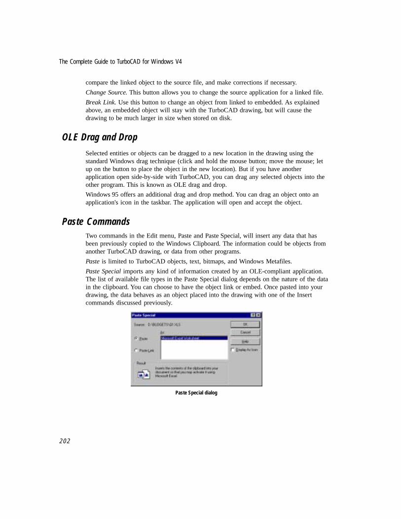
The Complete Guide to TurboCAD for Windows V4
2 0 2
compare the linked object to the source file, and make corrections if necessary.
Change Source. This button allows you to change the source application for a linked file.
Break Link. Use this button to change an object from linked to embedded. As explainedabove, an embedded object will stay with the TurboCAD drawing, but will cause thedrawing to be much larger in size when stored on disk.
OLE Drag and Drop
Selected entities or objects can be dragged to a new location in the drawing using thestandard Windows drag technique (click and hold the mouse button; move the mouse; letup on the button to place the object in the new location). But if you have anotherapplication open side-by-side with TurboCAD, you can drag any selected objects into theother program. This is known as OLE drag and drop.
Windows 95 offers an additional drag and drop method. You can drag an object onto anapplication's icon in the taskbar. The application will open and accept the object.
Paste CommandsTwo commands in the Edit menu, Paste and Paste Special, will insert any data that hasbeen previously copied to the Windows Clipboard. The information could be objects fromanother TurboCAD drawing, or data from other programs.
Paste is limited to TurboCAD objects, text, bitmaps, and Windows Metafiles.
Paste Special imports any kind of information created by an OLE-compliant application.The list of available file types in the Paste Special dialog depends on the nature of the datain the clipboard. You can choose to have the object link or embed. Once pasted into yourdrawing, the data behaves as an object placed into the drawing with one of the Insertcommands discussed previously.
Paste Special dialog

2 0 3
Chapter 12 Drawing Enrichment
Practice ExerciseFollow the steps below to practice using some of the commands and tools discussed in thischapter. Open the file CH12DET, created in Chapter Seven.
CH12DET.TCW before adding hatch and fill (left) and after
The steps below will guide you through:
• Adding a solid color fill to the rectangle in the lower part of the wall.
• Adding a hatch pattern to the interior of the wall.
• Placing a bit image file in the drawing
This drawing presents an interesting challenge, one that you are ready for if you haveworked through the exercises in this book. Because of the various objects used to define thewall, it is not possible to hatch the interior of the wall by simply selecting the boundaries. Itwill be necessary to trace along the interior. But there are both straight lines and a circledefining the boundaries of the area to be hatched. You will trace using first Multiline, thenArc Center and Radius.
It that weren’t enough, once you trace the interior of the wall, you will find it difficult if notimpossible to select only the tracings and not the elements of the wall when you try to placethe hatch pattern. To get around this problem, you will draw the trace lines on a newlycreated layer. Then to select the trace lines, you will set all layers to invisible except thelayer holding the trace lines. Place the hatch, then restore all invisible layers.
Place Solid Color Fill
1. Select Menu: View|Toolbars, and click on Entity Format, to add the Entity Formattoolbar to the desktop

The Complete Guide to TurboCAD for Windows V4
2 0 4
Entity Format toolbar
2. Right-click on the hatch tool in the Entity Format toolbar.
Hatch tool icon
3. Click on the Brush tab.
4. Select SOLID as the pattern, black as the color. Click OK to end.
5. Select the small rectangle near the bottom of the wall. Click on the Hatch tool in theEntity Format toolbar to fill the rectangle.
Place a black solid fill in the rectangle
Place Concrete Hatch
6. Right-click on the Hatch tool.
7. Set CONCRETE as the pattern (number 21 in the list), color to gray. Click theCrossed option to select it. Click OK.
8. From the menu, select Options|Layer. Type “Details” in the name field, and click onNew to create an new layer called Details. Click OK.
9. Select the Multiline tool from the Insert Entity toolbar, then right-click on theMultiline tool to summon the Properties dialog. In the General property sheet, selectDetails as the new layer. Click OK.
10. Select Snap Vertex in the Snaps menu.
11. Use Multiline to trace the interior of the wall, starting at the bottom left where thewall meets the circle. Click on the endpoints that define each corner of the interior,

2 0 5
Chapter 12 Drawing Enrichment
including the intersection of the wall and the circle on the right. Right-click andselect Finish from the local menu.
12. Select Arc Center and Radius from the Arc tool in the Insert Entity toolbar. Right-click and set the layer to Details.
13. To define the center of the arc’s radius, right-click and select Local Snap|Arc Centerfrom the local menu. Click on the circle.
14. Move the cursor to the lower left corner of the wall, where you started the multilinetracing. Click there to establish the radius, and again to start the arc.
15. Move the cursor to the right and click to finish the arc and close the tracing of thewall.
16. From the menu, select Options|Layer. Select Details.
17. In Properties, deselect Visible. The “eyes” icon representing a visible layer isremoved from Details.
18. Click the Toggle All button. Now Details is set to visible, and all other layers are setto invisible. Click OK.
Now only the tracing is visible
19. Use the Select tool to draw a selection rectangle around the tracing. Click on Hatch inthe Entity Format toolbar. You will not see any results yet.
20. Select Menu: Options|Layer again. Select Details, and click the Toggle All button. Allother layers will be set to visible again. Click the Visible button to set Details asvisible, too.
21. The complete drawing returns to the screen, including a concrete hatch pattern in thewall.

The Complete Guide to TurboCAD for Windows V4
2 0 6
Hatching completed
Insert Bitmap Image
22. Click on Zoom Extents in the View menu.
23. From the menu, select Insert|Object.
24. Leave the default Create New selected. Click on Bitmap Image and click the OKbutton.
25. A selection rectangle will appear in the drawing, and the Paint program will open.Scratch out a quick doodle, then double-click on the Control Menu box to exit Paintand return to TurboCAD. It is not necessary to save the doodle as a Paint file.
26. Press function key <F5> to redraw the screen. The doodle you created in Paint is nowvisible in the drawing.
27. Drag the bitmap to any part of the drawing.
28. Save the drawing and exit TurboCAD.
A Wealth of Interconnective OpportunitiesThe popularity of the Windows operating environment has made it easier for softwarepublishers to allow the import of files created by other programs. TurboCAD takes goodadvantage of such Windows features as OLE and the Clipboard, allowing you theopportunity to add content created in other programs to your TurboCAD drawings. Datacalculated in a spreadsheet, bit-map images from an illustration program, or even videoclips are all possible additions to your drawings. The creative possibilities of such links toother “documents” are unlimited.

13Printing and Plotting
Putting Your Designs on Paper
TurboCAD follows standard Windows protocols for printing, with additional commands inthe Page Setup dialog to match the needs of draftsmen and designers.
NOTE: In Windows, plotters are treated as printers. If you have a plotter, you need to installspecial Windows software known as a driver to use it with TurboCAD. If you don’t have adriver for your printer or plotter, contact the manufacturer of the device, not Microsoft.
Printer Paper and the Drawing SheetAs you draw in TurboCAD, you generally see the feature known as the drawing sheet. Asexplained in Chapter Two, the drawing sheet represents Paper Space. The unit of measure inPaper Space matches the units on the sheet you will print to. The drawing sheet can bevisible on-screen, yet you can be drawing in World Space (the place where objects aredrawn at their real-world size or any scale of it that you prefer).
The drawing sheet is not necessarily the same size as a single sheet of paper that comes outof your printer or plotter. The Drawing Sheet is the total surface area on which your drawingcan be printed. The Drawing Sheet can correspond to a single sheet of paper in the printer,or it can span multiple sheets of printer paper.
Both the printer paper and the drawing sheet have adjustable sizes, as well as landscape(wide) and portrait (tall) orientations. This provides a great deal of flexibility when youwant to print a large drawing on multiple sheets. You could, for example, print a poster inlandscape orientation three feet wide and two feet tall. You could print this virtual sheet outon 32 sheets of 8.5” x 11” paper oriented in portrait, or on 30 sheets of the same size paperoriented in landscape.
☞

The Complete Guide to TurboCAD for Windows V4
2 0 8
5' x 3' landscape drawing sheet on 8.5" x 11" portrait printer paper
5' x 3' landscape drawing sheet on 8.5" x 11" landscape printer paper
Simple Printing
TurboCAD makes it easy to print in a few simple steps. If you have a drawing created inWorld Space, and want to print it to one sheet of paper without regard to scale, follow thesesteps:
1. Choose Menu: File|Print. The Print dialog will appear.

Chapter 13 Printing and Plotting
2 0 9
Print Dialog
2. In the Print Range control group, click the All option to print your entire drawing.
3. Check the Fit on One Page option.
4. Click the Page Setup button to bring up the Page Setup Dialog. Choose your printer,paper size, and paper orientation, then click OK to return to the Print dialog.
5. Click the OK button to print your drawing.
Your drawing will be centered and printed on a single sheet of paper.
Tiled Printing
TurboCAD gives you two different approaches to printing a drawing on multiple tiled sheetsof paper, using the Paper and Layout property pages of the Page Setup dialog. The twofollowing sections describe these two options.
TIP: When printing on multiple tiled sheets, it is usually best to have the Print Crop Marksoption on, unless you can set your margins to zero. (Not all printing devices can accept zeromargins.) Crop marks will enable you to easily trim the edges of the paper so that the sheetscan be pasted onto a backing for display.
Tiled Printing by Setting Sheet Size
If you want to create a printout of a specific size tiled on multiple sheets, you can specifythe size of the printout in the Paper property sheet. TurboCAD will determine the numberand arrangement of the sheets of printer paper.
✔

The Complete Guide to TurboCAD for Windows V4
2 1 0
1. Choose Menu: File|Page Setup. The Paper property sheet will be visible in front.
Paper property sheet of Page Setup dialog
2. In the Printer Paper control group, specify the size of the sheets of paper that youwant to print on and whether you want to print in landscape (wide) or portrait (tall).
3. In the Sheet Size control group, specify the size of the area on which you want to printthe drawing and its orientation. You can do this in any units listed in the Menu:Tools|Units and Scale property sheet. For example, if you want a printout 2 feet talland 3 feet wide, you would type 2 ft. x 3 ft. in the list box, and choose the Landscapeoption.
4. Click the Fit button to place your drawing on the tiled sheets.
5. Click the Print button to print your drawing immediately, or click OK and thenchoose Menu: File|Print if you want to go through the Print dialog.
NOTE: You can also set the sheet size in either World or Page units by specifying values in theHeight and Width fields on the Layout property sheet.
Tiled Printing by Setting Rows and Columns
In the Layout property sheet of the Page Setup dialog, you can specify the number of rows(the number of sheets of printed paper from top to bottom) and columns (the number ofsheets of printed paper from left to right). You can then return to the Paper property sheet to
☞

Chapter 13 Printing and Plotting
2 1 1
fit your drawing onto the tiled printer paper. TurboCAD will automatically adjust thedimensions of the drawing sheet to accommodate changes in the number of rows andcolumns.
Layout property sheet of Page Setup dialog
Print Commands in the File menu
The following sections discuss each feature available in the File menu for printing andplotting.
Page Setup Dialog
The Page Setup dialog provides a rich set of features that let you determine exactly howdrawings will be printed. It consists of a minimum of two property sheets: Paper andLayout. For some printers, additional property sheets are required for advanced features.
TIP: After you have selected options in these property sheets, you can either make thechanges in your drawing by clicking the OK button at the bottom of the dialog, or print thedrawing from the dialog without making changes in your drawing by clicking the Print button. Ifyou click the OK button, you can then print the drawing by choosing Menu: File|Print orclicking the Print button on the Standard toolbar.
✔
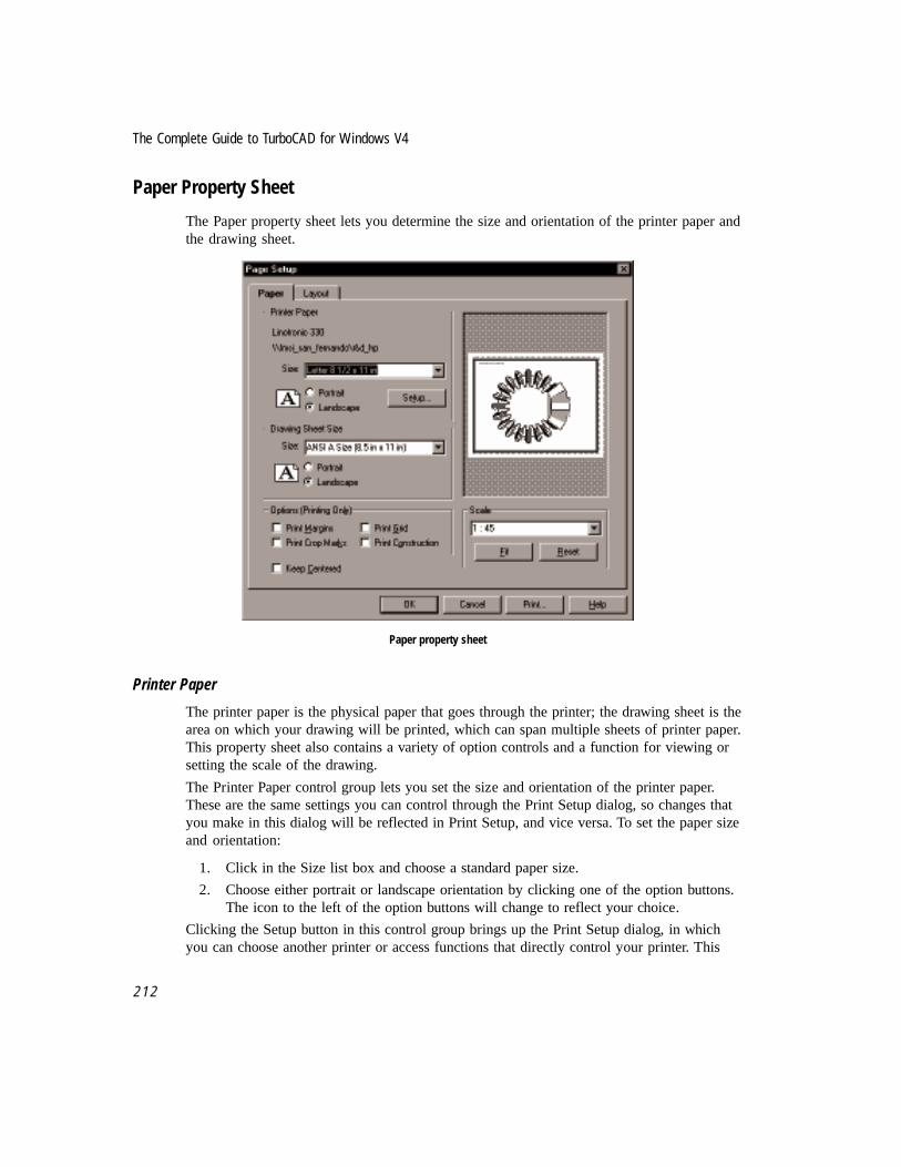
The Complete Guide to TurboCAD for Windows V4
2 1 2
Paper Property Sheet
The Paper property sheet lets you determine the size and orientation of the printer paper andthe drawing sheet.
Paper property sheet
Printer Paper
The printer paper is the physical paper that goes through the printer; the drawing sheet is thearea on which your drawing will be printed, which can span multiple sheets of printer paper.This property sheet also contains a variety of option controls and a function for viewing orsetting the scale of the drawing.
The Printer Paper control group lets you set the size and orientation of the printer paper.These are the same settings you can control through the Print Setup dialog, so changes thatyou make in this dialog will be reflected in Print Setup, and vice versa. To set the paper sizeand orientation:
1. Click in the Size list box and choose a standard paper size.
2. Choose either portrait or landscape orientation by clicking one of the option buttons.The icon to the left of the option buttons will change to reflect your choice.
Clicking the Setup button in this control group brings up the Print Setup dialog, in whichyou can choose another printer or access functions that directly control your printer. This

Chapter 13 Printing and Plotting
2 1 3
dialog is specific to your printer driver. Check your printer or printer driver documentationfor details.
Drawing Sheet Size
The Drawing Sheet Size control group lets you control the size and orientation of the areaon which your drawing will be printed. This area can be imposed on a single sheet of printerpaper, or it can span multiple sheets of printer paper. Its orientation can also be setseparately from the orientation of the printer paper. To set the size and orientation of thedrawing sheet:
1. Click in the Size list box and choose a standard paper size, or type in a custom sizeusing standard measurements (for example, 2 ft. x 2 ft.).
2. Choose either portrait or landscape orientation by clicking one of the option buttons.The icon to the left of the option buttons will change to reflect your choice.
The page display on the right side of the dialog will change to reflect the relationshipbetween printer paper and drawing sheet size and orientation.
Options (Printing Only)
The buttons in the Options (Printing Only) control group let you determine what elementsare printed. These options affect only the printing of the drawing and are not reflected in theappearance of the drawing on-screen.
Print margins. Check this button to print a border on the margin of the printer sheets. This isuseful for framing the drawing if it is printed on a single sheet.
Print crop marks. Check this option button to print crop marks on the printer sheets. This isuseful if you want to print across multiple printer sheets and crop the sheets so that they canbe pasted against a backing.
Print grid. Check this option if you want to print grid marks. The grid will be printed if it iscurrently displayed.
Print construction. Check this option if you want to print construction lines.
Page Layout Scale
The controls in the Scale control group let you scale the drawing so that it fits within thedrawing sheet, or lets you choose a custom scale.
To scale the drawing so that it fits into the drawing sheet, click the Fit button. The drawingwill be centered as it is fit onto the drawing sheet.
To choose a custom scale, click in the list box and choose a preset scale, or type a scaledirectly into the list box in the form 1 in = 1 ft. When typing custom scales, you can use anymeasurement available in the Units and Scale property sheet of the Drawing Setup dialog(from the menu select Tools|Drawing Setup). You can click the Reset button at any time to

The Complete Guide to TurboCAD for Windows V4
2 1 4
return to the scale that was set when you entered the Page Layout dialog. Drawing Setup isalso discussed in Chapter 3, under the heading Preparation For Drawing.
Keep Centered
Check the Keep Centered option to keep the drawing centered over the drawing sheet.
Layout Property SheetThe Layout property sheet gives you direct control of the number of rows and columns ofprinter paper. It also has functions for setting the printer paper margins, setting the heightand width of the drawing sheet in either World or Paper units, and relocating the paper inthe drawing area.
Layout property sheet of Page Setup dialog
Margins
Margins, the dotted rectangle inside the edges of the paper, let you know whether you aredrawing inside or outside the printable area of your drawing.
The margins control group contains four text boxes in which you can specify the top,bottom, left, and right margins of the printer paper in Paper units. By default, the marginsare displayed in units set in the Units and Scale property sheet (Menu: Tools|DrawingSetup), but you can enter values in other units as well.

Chapter 13 Printing and Plotting
2 1 5
NOTE: You cannot set the margins of the drawing sheet independently of the margins of theprinter paper.
TIP: If you set all the margins to zero, TurboCAD will offer to set them back to give you thebiggest possible printable area on the current printer.
Rows and Columns
The Rows and Columns controls let you set the number of rows and columns of the printersheet paper, for tiled printing. As you increase the number of rows and columns, the size ofthe drawing sheet — the area on which your drawing will be printed — increasescorrespondingly. The Paper Height and Paper Width controls let you directly set the heightand width of the drawing sheet. As you increase these values, TurboCAD will automaticallyincrease the number of rows and columns to accommodate the change in the drawing sheetsize.
Origin
The Origin boxes let you move the paper to a different location in the drawing. You do thisby specifying the location of the lower-left corner of the paper in absolute coordinates: Typethe horizontal coordinates into the X box and the vertical coordinates into the Y box.
TIP: This feature is useful if you want to print a particular area of a large drawing by relocatingthe paper to the area that you want to print.
Print Dialog
Print dialog in Windows 95
✔
✔
☞

The Complete Guide to TurboCAD for Windows V4
2 1 6
The Print dialog (Menu: File|Print or <Ctrl> + <P>) provides a set of functions whichinclude printing a single view of a drawing, or printing specific sheets in a drawing thatspans multiple sheets of printer paper.
Print Source
The Print Source control group lets you choose whether to print all of the drawing objects,or only those that are currently selected.
Print RangeThere are times when you will only need to print a portion of a drawing that would spanseveral pages when printed in its entirety. Use the features of the Print Range group to set aspecific view of the drawing to print, and to select a range of pages when printing a drawingthat spans multiple printed sheets.
All. Select this option if you want to print all of the current drawing. If you have chosenSelection in the Print Source control group, only objects that are selected will be printed. (Ifyour drawing spans multiple printer sheets, the total number of sheets will be shown in thisoption label.
View. This option allows you to select a Named View, if one exists in the drawing.
Fit on 1 page. Check this box if you want to print everything on a single page.
CopiesType the number of copies of the drawing that you want to print in the copies text box.

14Drawing Import and Export
Using Design Files in a Mixed Environment
Sooner or later, you will need to share a TurboCAD drawing with a non-TurboCAD user.The drawing may be headed for desktop publishing, a plotter service, or even another CADprogram. Almost every graphics program has its own file format, and translation from oneformat to another can often become complicated and frustrating. The more you know aboutthe major graphic file formats, the better chance of success you will have when you need totranslate your TurboCAD drawings.
This chapter discusses the variety of file formats that you are likely to encounter as aTurboCAD user. The list includes formats used by previous versions of TurboCAD, and fileformats used by other CAD programs.
File formats created by bit-image (raster) software is not included in this chapter. For detailson using bit-image graphics as objects in a TurboCAD drawing, refer back to ChapterTwelve.
TurboCAD proprietary formatsTurboCAD is no different from every other drawing program on the market, it uses aproprietary format to store the images you create. If you Save a drawing without specifyingan alternative file format, the drawing is saved in the .TCW format, short for TurboCADWindows.
Every new release of a software program offers new features. Some features are obvious tothe user, others are buried beneath the surface. It is common practice for softwarecompanies to revise the internal workings of how programs store information in files, for avariety of reasons. The publisher may wish to improve the speed at which drawings are
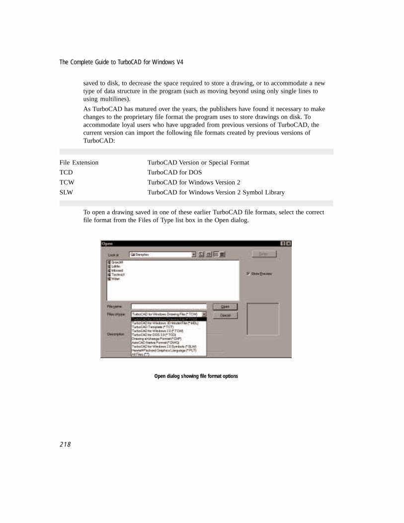
The Complete Guide to TurboCAD for Windows V4
2 1 8
saved to disk, to decrease the space required to store a drawing, or to accommodate a newtype of data structure in the program (such as moving beyond using only single lines tousing multilines).
As TurboCAD has matured over the years, the publishers have found it necessary to makechanges to the proprietary file format the program uses to store drawings on disk. Toaccommodate loyal users who have upgraded from previous versions of TurboCAD, thecurrent version can import the following file formats created by previous versions ofTurboCAD:
File Extension TurboCAD Version or Special Format
TCD TurboCAD for DOS
TCW TurboCAD for Windows Version 2
SLW TurboCAD for Windows Version 2 Symbol Library
To open a drawing saved in one of these earlier TurboCAD file formats, select the correctfile format from the Files of Type list box in the Open dialog.
Open dialog showing file format options

Chapter 14 Drawing Import and Export
2 1 9
Drawing Exchange Format -- DXF
DXF is a file format created by Autodesk, Inc., makers of AutoCAD. This format hasbecome the standard file exchange type for CAD drawings. Virtually every CAD program onthe market can read this format. It is usually your best bet if you need to share drawingswith the user of another CAD program. DXF will generally preserve your layer definitions,line types and line colors as you created them.
To save a TurboCAD drawing in DXF format, select Menu: File|Save As, then select DXFfrom the Save As Type: list box.
Improving the Readability of DXF filesDXF is widely accepted, but has its limitations. The format does not support the use of solidcolor fills and hatch patterns. Also, DXF does not support the use of TrueType fonts, whichspells trouble for any Windows-based CAD program, including TurboCAD.
There are steps you can take to improve the readability of your drawings when convertingthem to DXF. Make sure you completely finish the drawing before you create a DXFversion. Always keep an original version of the completed drawing in TurboCAD’s TCWformat. Use the Menu: File|Save As command to create a second copy of the drawing (witha different name), which you will modify before translating to DXF.
Use Menu: Format|Explode to reduce complex elements to basic entities. Your goal is tocreate a drawing of simple lines, with no complex elements. You should explode all hatchpatterns, color fills and lines of text until they are polylines. Explode all groups and blocksto their original constituent parts. Depending on the complexity of the drawing, you mayhave to explode some elements three or four times before you reduce these elements tosimple entities. TurboCAD can explode any number of objects one level deep each time youuse the command.
DWG: AutoCAD native file formatIn addition to DXF, TurboCAD can save drawings in AutoCAD’s native DWG format.TurboCAD supports the DWG format as used by AutoCAD Release 12. Most earlier versionof AutoCAD as far back as Release 9 should also be able to import DWG files created byTurboCAD.
The guidelines provided above for creating reliable DXF files also apply to DWG files.
HP-GL and HP-GL/2: Hewlett Packard Graphics LanguageThe DXF and DWG formats are best used when sharing your drawings with another CADuser. If you need to send drawings to a plotting service, you will most likely need totranslate your drawing to either HP-GL or HP-GL/2, the most common plotter file formats.Before you start the translation, find out if there is a plotter driver for your version of

The Complete Guide to TurboCAD for Windows V4
2 2 0
Windows that is an exact match for the plotting device. If so, install it into your version ofWindows.
HP-GL is a popular graphics format that is used by both vector and raster graphicsprograms. HP-GL/2 is an updated version. The language was originally created as a set ofcodes to send graphics images to Hewlett Packard pen plotters.
TurboCAD 4 for Windows can both open an HP-GL file from the Open menu, and directlysave a file in either HP-GL format. This is a change from TurboCAD Version 3, whichrequired you to “print to disk” to create an HP-GL file from a TurboCAD drawing.
Given the same original drawing, HP-GL files are usually smaller than DXF files. Solidcolor fills and hatch patterns should translate successfully, but you will still need to explodeany text in the drawing.
Third-party program for file conversionMany CAD users have found a shareware program called PrintGL to be of benefit whentranslating files. PrintGL is a pen plotter emulator package for DOS and Windows. It readsand displays HP-GL and HP-GL/2 data from CAD and graphing packages. It supports awide variety of 9- and 24-pin printers, ink jet and laser printers. It can export PLT files toPostScript (EPS or device files), and to PCX (Paintbrush) format. You may modify someelements of the PLT file in PrintGL, such as specifying colors or adjusting line types.Another good use of PrintGL is to view PLT files you have created from your TurboCADdrawing, before you pass them along. Some CAD users prefer to use PrintGL as a printerdriver, instead of relying on the drivers provided with Windows. This is especially true ifyou must rely on the HP7475A driver, which has documented problems. PrintGL isavailable for download on the Internet at http://www.shareware.com, on CompuServe in theGraphics Support Forum Library, and on the Ravitz Software BBS at 606-268-0577. IMSIdoes not endorse PrintGL, and can provide no support if you use it.
Exporting TurboCAD Drawings Using OLE Drag and Drop
Any Windows program that supports standard Windows Object Linking and Embedding(OLE) can accept a TurboCAD drawing. Open both programs side-by-side. Click on thedrawing’s reference handle and drag the drawing into the second program. A second methodis to Cut or Copy the drawing or selected elements to the Windows clipboard, then use thePaste command in the second program. OLE is described in more detail in Chapter Twelve.

Chapter 14 Drawing Import and Export
2 2 1

The Complete Guide to TurboCAD for Windows V4
2 2 2

15Customizing the Desktop
Reshaping TurboCAD to match your work style
As a worker becomes more skilled, there is a natural tendency to personalize the tools ofone’s craft. TurboCAD’s customization features make it possible for users to reshape theTurboCAD desktop to match personal work style.
The reference manual that ships with TurboCAD for Windows Version 4 includes a completediscussion on all forms of program customization; that information will not be duplicated inthis chapter. Instead, this chapter provides a brief tutorial introducing the customizationprocess.
Why change the desktop?
When the topic of customization comes up, some people say “Why bother? Just learn to usethe program the way it comes out of the box.” Consider the three scenarios that follow, eachoffering a valid reason to customize the TurboCAD desktop.
Limited need. A set designer uses TurboCAD to create diagrams for outdoor stage shows.The tools and commands she needs most are a relatively small subset of the program’sfeatures. She only uses two line tools and one circle tool, and generally ignores the otherentity tools. After a while, the designer realizes she can remove all the existing toolbars onthe desktop, replacing them with one toolbar along the top, making more room available forviewing the drawing. The two line tools and one circle tool she uses can be combined intoone fly-out toolbar; three important tools now occupy one icon width on her new toolbar.
Preference for the keyboard. In this era of Windows icons and toolbars, a facilities managerwho misses DOS still prefers to use keyboard shortcuts as much as possible. He uses [Alt]-

The Complete Guide to TurboCAD for Windows V4
2 2 4
[F4] to close the program, and knows that the [Alt]-I, L, S keystroke sequence will select theSingle Line command. To him, to remove your hand from the keyboard and not draw a lineis a waste of time. The ability to link TurboCAD commands to keystrokes will not only savethis user time, but decrease interruptions in the creative process.
Training new users. A network support manager for a Fortune 500 company manages agroup of 25 network technicians. Each technician must maintain accurate diagrams for theirareas of responsibility. The manager creates custom menus and toolbars for eachtechnician’s copy of TurboCAD, increasing staff productivity and shorten learning time.
Create a personal workspaceThe following tutorial will introduce the process of customization. After you becomefamiliar with the process, take the time to review your work style and see if you can comeup with ideas for creating a custom TurboCAD workspace.
Create a new toolbar
New toolbars may be created using the Tools|Customize|Toolbars dialog. After providing aname for the new toolbar, use the Categories list to find the specific tools or commands youwish to assemble into a toolbar. The toolbar icons for each command will appear in theButtons field. Select a category, then click on a button to see its description at the bottom ofthe dialog. If you want to add the button to your new toolbar, drag it into the toolbar.
Follow the steps below to practice creating a new toolbar.
1. Launch TurboCAD. Accept the default template to start a new drawing.
2. From the menu, select Tools|Customize
3. Click on the Toolbar tab at the top of the dialog.

Chapter 15 Customizing The Desktop
2 2 5
Customize dialog
4. Drag the New button out of the Customization dialog and onto the desktop.
5. The New Toolbar dialog will appear. Type “Lines” and click on OK.
Name the new toolbar
6. In the Categories list, click on the small plus sign to the left of Insert.
7. In the list of items under Insert, click on Line.
8. In the Buttons display, click on the Single Line tool icon (first icon, top row). Adescription of the tool appears in the lower left corner of the dialog.

The Complete Guide to TurboCAD for Windows V4
2 2 6
Adding the Single line tool to the new toolbar
9. Drag the Single Line icon onto the new toolbar, which can be found in the same spotwhere you dragged the “New” button.
10. Click on the Perpendicular Line icon (last icon, top row), and drag it into the newtoolbar.
11. Click on the Double Line icon (first icon, bottom row). Drag it into the new toolbar.
Three tools added to new toolbar (to the right of the dialog)

Chapter 15 Customizing The Desktop
2 2 7
Add fly-out tools to the toolbar
In this next section, you will add one more tool to the Lines toolbar. This new tool willfunction as a fly-out – it will only appear when you click and hold on the top tool in thegroup of fly-outs. While the new tool appears as a fly-out on the Lines toolbar, TurboCADsaves the information about this new tool icon as if it were a separate toolbar.
1. In Categories, click on Double Line
2. Under Style, click Fly-out.
3. In Buttons, click the Single Double Line tool icon (first icon, top row).
4. Drag the icon and place it directly on top of the Double Line icon in the new toolbar.
5. A “New Toolbar” dialog appears. Type “Dbl” and click the OK button.
6. The two double line tools should appear as fly-outs, as illustrated below.
Fly-out tools extend from new toolbar
Create a new menu
Custom menus may be created using the Tools|Customize|Menus dialog. To create a newmenu, first open the Customize Menus dialog. Then select the item labeled [Menu Bar]from the Change What Menu list. Click on the Add Submenu button, name the new menuand click OK.
Follow the steps below to place a command in a new menu.
1. Click on the Menus tab at the top of the Customization dialog.

The Complete Guide to TurboCAD for Windows V4
2 2 8
2. In the Change What Tab field, click on [Menu Bar], the top item in the list. (Youmay have to scroll to find the item.)
3. Click the Add Submenu button.
4. In the “Name the new menu” dialog, type Lines and click the OK button.
Name the new menu
5. In the Categories list, select Insert.
6. In the Commands list, select InsertLineSingle.
7. In the Change What Menu list, click on Lines. You may need to scroll to the bottomof the list to find Lines.
8. Click the Add button.
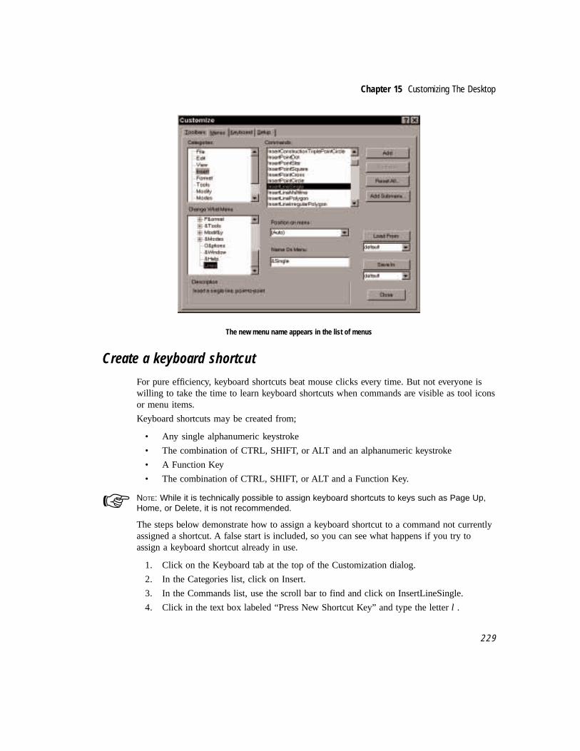
Chapter 15 Customizing The Desktop
2 2 9
The new menu name appears in the list of menus
Create a keyboard shortcut
For pure efficiency, keyboard shortcuts beat mouse clicks every time. But not everyone iswilling to take the time to learn keyboard shortcuts when commands are visible as tool iconsor menu items.
Keyboard shortcuts may be created from;
• Any single alphanumeric keystroke
• The combination of CTRL, SHIFT, or ALT and an alphanumeric keystroke
• A Function Key
• The combination of CTRL, SHIFT, or ALT and a Function Key.
NOTE: While it is technically possible to assign keyboard shortcuts to keys such as Page Up,Home, or Delete, it is not recommended.
The steps below demonstrate how to assign a keyboard shortcut to a command not currentlyassigned a shortcut. A false start is included, so you can see what happens if you try toassign a keyboard shortcut already in use.
1. Click on the Keyboard tab at the top of the Customization dialog.
2. In the Categories list, click on Insert.
3. In the Commands list, use the scroll bar to find and click on InsertLineSingle.
4. Click in the text box labeled “Press New Shortcut Key” and type the letter l .
☞

The Complete Guide to TurboCAD for Windows V4
2 3 0
5. A message appears below the letter, saying “Currently Assigned toModesSnapRelocate.”
Message indicates keystroke is already assigned to a command
6. Press [Alt]-L. Now the message reads “Currently assigned to [unassigned].”
7. Click the Assign button to accept [Alt]-L as the new keyboard shortcut for the InsertSingle Line tool.
Saving customization changes
When you have finished your desktop and keyboard customization, you will want to savethe changes you have made so they become a permanent part of TurboCAD. Do not followthe steps below unless you wish to save the changes made in this tutorial as a part of yourTurboCAD desktop.
A button called Save In appears on each of the three dialog used in this tutorial. To savechanges, click on the text box below the Save In button and type a file name. All thecustomization changes will be saved in this file. If you want the changes to be a permanentpart of the TurboCAD desktop, and you don’t care about preserving the original desktop andsettings, you may leave “Default” as the file name listed in the Save In text box.
When you click the Save In button, a dialog will appear, asking “Are you sure you want toupdate the existing file?” Click the Yes button. To finish, click Close.

16Increasing productivity
Tools and tips for efficiency
If you have worked through each chapter, by now you have gained experience with mostelements of the program. You have probably taken your new skills and started to work onone or more projects of your own. As well you should – you didn’t buy TurboCAD just towork a few tutorials.
Previous chapters have explored how to draw and edit in TurboCAD. This last chapter willintroduce a few features that do not directly draw or edit, but do increase your overallefficiency. These features fall into three categories:
• Views of the drawing
• Measurements
• Keyboard shortcuts
Creating and using additional viewsAs a drawing becomes larger and more complicated, there are times when it is easy tobecome lost in the details. If you need to zoom in and work on a small portion of thedrawing, you can lose your perspective of how the small details relate to the whole of theproject. Wouldn’t it be nice if you could have your cake (see the entire drawing) and eatyour cake (see a close-up view) at the same time? You can.
In addition to the zoom, pan, and view commands introduced in Chapter Five, TurboCADoffers three tools that can increase your efficiency by giving you two or more views of yourdrawing at the same time.
Aerial View. This tool opens a second view of the drawing in a special window. Navigation

The Complete Guide to TurboCAD for Windows V4
2 3 2
tools included in the window make it easy to adjust the view in the main drawing window.
Viewport. Take advantage of a previously Named View without dedicating the entire screento it. The named view becomes an object in the drawing. Not only is this tool useful forviewing parts of the drawing, it may be used to create call-outs or details.
Multiple Windows. Open more than one window on the drawing, and draw or edit in any ofthem.
Of the three, only Multiple Windows allows you the ability to draw and edit – Aerial Viewand Viewport are for reference and navigation. Follow the steps below to gain experiencewith each of these features.
Using Aerial View
Aerial View gives you the option of a second view of the drawing. The view may be partial,at any zoom factor, or it may be a miniature view of the full drawing. Once you havecreated an Aerial View, you may use it to quickly change the zoom factor of the maindrawing window.
To create an aerial view, click the Aerial View icon (the airplane) in the View toolbar. Thenuse the cursor to draw a selection rectangle around the part of the drawing you want toappear in the Aerial View. An Aerial View window will open in the area of the screen whereyou drew the selection rectangle. You may drag the Aerial View by the title bar to move itto any other part of the screen, or resize it as you would any window.
Grarchfl.TCW is a large, detailed drawing that ships with TurboCAD. Follow the stepsbelow to use Aerial View in this drawing.
1. Launch TurboCAD and open IMSI\TCW40\Samples\Grarchfl.TCW.
2. Click the Aerial View tool (the airplane) in the View toolbar, along the right side ofthe desktop.
Aerial View tool icon
3. A dotted-line rectangle appears on the cursor. Draw a selection rectangle around theset of objects in the top left corner of the drawing. When you finish the rectangle, anAerial View window will appear.

Chapter 16 Increasing Productivity
2 3 3
Aerial View floats above the drawing
Aerial View tools
Six tools are available in Aerial View. Five have icons inside the Aerial View window; thesixth is activated by cursor position. Note that the five tool icons are in two groups. The firstthree affect the view inside the Aerial View window; the last two are used inside the aerialview window, but affect the drawing. The standard window tools Reduce/Restore and Closeare also provided in the top left corner.
TIP: Use the Aerial View Reduce/Restore tool to temporarily “roll up” the Aerial View as if itwere a curtain; the title bar will remain. Click the tool again to restore the Aerial View.
From left to right along the Aerial View title bar, the tools are:
Aerial Zoom In. Reduce the current aerial view by 50 percent.
Aerial Zoom Out. Increase the current aerial view by 50 percent.
Aerial Zoom Extents. Display the entire active drawing in the Aerial View window.
Aerial Zoom Window. Select a new view for the drawing with a red selection rectangle in theaerial view.
Aerial Pan View. Select a new zoom view for the main drawing window by moving theAerial Zoom Window rectangle to a new location in the Aerial View.
Aerial Cursor Pan. (No tool icon) Pan the main drawing window view using the AerialView. To use, place the cursor just inside a border of the aerial view window. After a pause,the cursor will change to a small solid arrow and start panning the drawing in the directionthe arrow points. Move the cursor away from the edge to end panning.
✔

The Complete Guide to TurboCAD for Windows V4
2 3 4
Follow the steps below to gain experience using Aerial View tools.
1. Click Aerial Zoom Extents The entire drawing will appear in the Aerial View.
Aerial Zoom Extents tool icon
2. Click Aerial Zoom Window.
Aerial Zoom Window tool icon
3. Click and drag to draw a selection rectangle inside the Aerial View window. Thedrawing in the main window will zoom to match the borders of the selectionrectangle.
Aerial zoom view with selection rectangle

Chapter 16 Increasing Productivity
2 3 5
The red rectangle that appears when you use Aerial Zoom Window remains inside the AerialView until you use either Aerial Zoom In, Aerial Zoom Out, or Aerial Zoom Extents. Whenthe red rectangle appears inside an Aerial View, Aerial Pan Window may be used to select anew view for the active drawing.
1. Click on the Aerial Pan Window tool.
Aerial Pan Window tool icon
2. Move the cursor into the Aerial View. A rectangle the size of the previous selectionrectangle is attached. Click anywhere inside the Aerial View to zoom the activedrawing to match the view inside the rectangle.
The new view set by using Pan Window
3. Click on the Aerial Pan Window tool to end the function and remove the rectanglefrom the cursor.
4. Experiment with Aerial Cursor Pan. From inside the Aerial View, move the cursortoward any border of the window. The cursor will change to a small solid black arrow,and the view inside the Aerial View will pan in the direction the cursor points.

The Complete Guide to TurboCAD for Windows V4
2 3 6
Using Viewports
If you have previously saved specific views of the drawing using the Named Viewcommand, you may use the Viewports command to insert a Named View into the drawing.The inserted view become an object in the drawing.
The Named View inside the viewport is linked to the original objects in the drawing. Youshould think of anything that appears inside a Viewport as a reflection of the original. If youedit or delete any object reflected in the Viewport, the image in the viewport will change tomatch.
The Viewports command is useful for adding a second view on the screen, but you mustrealize that in using the command you are adding a new object to the drawing.
TIP: To delete a viewport, click on the border, not on any object inside.
Follow the steps below to gain experience using Viewports. First, a named view will becreated, then inserted into the drawing using the Viewports command.
1. Click the Close button on the Aerial View.
2. Click on Zoom Window in the View toolbar.
3. Draw a selection rectangle around any small portion of the drawing. The screen willredraw to match.
4. From the menu, select View|Named View. In the Name text box, type “Insertion 1.”
Naming a view
✔

Chapter 16 Increasing Productivity
2 3 7
5. Click on Zoom Full View in the View toolbar.
6. Select Menu: Insert|Viewport.
7. Draw a selection rectangle in the blank area of the drawing (lower right quadrant).
8. The Named View dialog will appear. Click on Insertion 1 from the list. Click the GoTo button, then the Close button. A rectangle will be inserted into the drawing, andthe objects visible in the previously named view will appear inside it.
New viewport inserted into drawing
Using Multiple Windows
A third way to gain an additional view of your drawing is to open a second (or third, etc.)drawing window. You can set the view in each drawing to match your needs, and can drawin either window. Only one window will be active at any one time.

The Complete Guide to TurboCAD for Windows V4
2 3 8
Using Multiple Windows to view a drawing
To add a second window to the desktop, select Window|New Window. If the first windowwas maximized, the second window will also be maximized, and initially you will only seeone window, the new one. To see both windows, select Window|Cascade from the menu.
Measuring objectsThe objects you draw are representations of real-world objects. You draw them at their truesize. If a drawing contains a number of items (such as an office layout, a kitchen design, ora site plan), then the distances between items must also be represented accurately.
As you draw, it is sometimes necessary to know the exact size of an object, or the distancebetween two objects in the drawing. New in TurboCAD 4 are four measurement commands.They are:
Coordinates of the Point. Determine the exact X, Y address of an endpoint, a node, or anyobject or location in the drawing.
Distance. Measure the distance of a line, or the distance between any two specified points.
Angle. Measure the angular distance, in degrees, between two lines.
Area. Automatically calculate the area of any closed object, or of any perimeter youidentify.
Create a new drawing, then use it to practice the four measurement commands.

Chapter 16 Increasing Productivity
2 3 9
1. If Grarchfl.TCW (the previous drawing) is still open, close it (Menu: File|Close).
2. Select Menu: File|New to start a new drawing. Select the Normal template.
3. Click and hold on the Single Line icon in the Insert Entity toolbar, to open the SingleLine fly-out toolbar.
4. Select the Rectangle tool.
5. Draw a rectangle in the middle of the sheet that covers approximately a third of thesheet, as illustrated below.
6. Again open the Single Line fly-out toolbar (click and hold on the Rectangle icon).Select the Multiline tool.
7. Draw two lines to form an angle, as illustrated below. Right-click and select Finish toend.
Rectangle and lines for the next exercises
Measure coordinate locations
The results calculated by the various measurement commands are displayed in theMeasurement palette. It must be visible before you use any of the commands.
1. From the menu, select View|Measurement Info. The Measurement Info dockingpalette will appear on the desktop.

The Complete Guide to TurboCAD for Windows V4
2 4 0
TIP: Docking palettes can float on the desktop, or they can be attached (docked) to the sidesof the desktop. To dock a floating palette, drag it to one side or toward the top of the screen.To float a docked palette, double click on the thin margin that separates the informationscreen from the palette border. Double-clicking on this same margin when the palette isfloating will also cause it to dock.
2. From the menu, select Tools|Measurement|Coordinates of the Point.
3. Move the cursor toward any corner of the rectangle. When very close, press V on thekeyboard.
NOTE: Pressing V is a keyboard shortcut for the Snap Vertex command. It is an example of aSingle Entry Keyboard Equivalent – or SEKE. A list of SEKEs is provided in the last section ofthis chapter.
4. The X, Y coordinates of the location just selected will appear in the MeasurementInfo palette. Both World Coordinates and Paper Coordinates will be shown.
Measuring coordinates of the point
Measure distance
1. From the menu, select Tools|Measurement|Distance.
2. Move the cursor toward the far end of the top line defining the angle.
3. When very close, press V on the keyboard.
✔✔✔✔✔
☞

Chapter 16 Increasing Productivity
2 4 1
Measuring distance
The Measurement Info palette now displays three distinct data types, for both WorldCoordinates and Paper Coordinates:
Distance. Dist= in the palette is the distance between the two points selected.
Absolute Coordinate Distance. Correspond to the first and last points: has two parts,Delta X: and Delta Y:. This is a measurement of the absolute horizontal (X) and vertical (Y)distance from the first point to the second.
Angle. This is a measurement of the angle – or ray – defined by the two points, as it sits onthe coordinate plane. A line pointing true horizontal (three o’clock) would have an angle of0 degrees.
4. Right-click to summon the local menu, and notice the measurement display options.Click on one, and notice the change in the Measurement Info palette.

The Complete Guide to TurboCAD for Windows V4
2 4 2
Options for measurement units in the local menu.
When using Measure Distance, the local menu provides unit display options. Selecting oneof these options will cause the display in the Measurement Info palette to update, expressingthe value in the selected unit of measurement.
NOTE: Changing the unit of measurement in the Measurement Info palette does not changeany other setting in TurboCAD.
Measure angle
1. From the menu, select Tools|Measurement|Angle.
2. Using V as a keyboard shortcut for Snap Vertex, select each of the three points thatdefine the angle inside the rectangle.
3. When finished, view the results in the Measurement Info palette.
☞

Chapter 16 Increasing Productivity
2 4 3
Measuring an angle
The angle shown is the angular distance in degrees between the two lines. Now try adifferent method of selecting the lines that form the angle.
4. Press ESC to remove the previous measurement.
5. Right-click, and select By entity from the local menu.
6. Click anywhere on each line. It is not necessary to use a snap command to identifythe lines.
Selecting the By entity option in the local menu
By Entity allows you to select any part of an object for a measurement command. Whileuseful, it is not always the best way to select points in a measurement command.

The Complete Guide to TurboCAD for Windows V4
2 4 4
Measure Area
1. From the menu, select Tools|Measurement|Area.
2. Make sure Select By Entity is not active. If necessary, deselect it in the local menu.
3. Move the cursor to any corner of the rectangle. When very close, press V on thekeyboard for Snap Vertex.
4. Continue around the rectangle, selecting each corner. When you select the fourthcorner, the rectangle will be filled and the area of the rectangle will be displayed inthe Measurement Info palette.
Measuring the area of an object
As with Measure Distance, you can change the units of measurement on display in thepalette with the local menu.
Note: To measure the perimeter of a rectangle, use Measure Distance, selecting the entireboundary as you did above with Measure Area.☞

Chapter 16 Increasing Productivity
2 4 5
Using Keyboard ShortcutsThe old cliché “save the best for last” is hereby invoked. New to TurboCAD 4 are SingleEntry Keyboard Equivalents – SEKEs for short. They provide quick, one-key access to manyof the most commonly used commands and tools in TurboCAD.
Most SEKEs are snap commands. But a few perform other functions. Here is a completelist of SEKEs, in alphabetical order.
A – Set Absolute Coordinates. All coordinate references will be in Absolute Distances.
C – Snap Arc Center. Connect to the center of an arc or circle.
G – Snap Grid. Connect to the nearest grid point or intersection.
H – Snap Opposite. Continue line same distance from object as from first point to object.
I – Snap Intersection. Connect to the intersection of two entities.
J – Snap Single Projection. ?????????????????????????
M – Snap Middle Point. Connect to the midpoint of an entity.
N – Snap Nearest on Graphic. Connect to the location the cursor touches.
P – Set Polar Coordinates. All coordinate references will be Polar (distance and angle).
Q – Snap Quadrant Point. Connect to the nearest quadrant point on a circle or arc (0, 90,180, 270).
R – Set Relative Coordinates. All coordinate references will be in Relative Distances.
S – No Snap. Enter the location of the point.
V – Snap Vertex. Connect to the end of the line or other object.
X – Lock X. Lock the current X position as displayed in the Edit Bar.
Y – Lock Y. Lock the current Y position as displayed in the Edit Bar.

The Complete Guide to TurboCAD for Windows V4
2 4 6
IndexSymbols
$CONSTRUCTION 94*.TCW 220+ 76.TCW format 217<Shift> 72@ symbol
in group names 29
A
absolute coordinates 5, 73Advanced Grid 51Align Along Line 94Align Bottom 94Align Center 95Align Left 95Align Middle 94Align Right 95Align Top 95Aligning Objects 94Alignment 130alignment box 133American Institute of Architects 135angle
bisecting 89definition of 83dividing 90using 83
Angle Nodecommand 183
Angular Dimensiontool 174
Angular Dimension 174Angular Dimensioning
tool 180
angular dimensioning 179aperture 71Appropriate computer hardware iiiarc
aligning text to 121center and radius tool 141circumference of 153definition of 84Double Point tool 141drawing 153elliptical 142, 160entities tangent to 153placement 144placing 142radius of 153rotated elliptical 142Start/Included/End (1-2-3) 142tangent to arc 141tangent to line 142tool 141
Arc Center and Radiustool 143, 144, 145
Arc Tangent to 3 Arcs 142architectural drawing
standards in 187Area 77area 47Array Copy
tool 58Arrowheads 171attribute 131attributes 131AutoCAD 198automatic dimensioning 169automation
and CAD 3

The Complete Guide to TurboCAD for Windows V4
i i
B
Baseline Dimension 174Bezier 196Bezier curve 162bisecting
a line 85, 87angle 89
bit-image 217bitmaps 8Blocks 139blocks 30, 219BMP 198brush properties 134Brush setting 192
C
CAD, DOS-based 114CAD management system 131cam assembly 154Cartesian coordinates 72Cartesian coordinates 5CD-ROM iiiCenter and Point
tool 53Chamfer 108
tool 108using Edit bar 108
chorddefinition of 85
circle 53aligning text to 121definition of 84
Circle tools 53Circle Center and Point 145, 155Circle Tangent to Arc 154Circle Tangent to Line 154Tangent Arc Point 154Tangent From Arc 154Tangent to 2 Arcs 154Tangent To Arc 154
Circumference 84Cleanup option 111
Clipboard 206clockwise rotation 42closing multilines 167color
creating new 133number of 133of grid 52
colors 133columns and rows
printing in 215command
definition of 7Computer Aided Design 1Concentric 53Concentric Arc 79, 141construction
points 163techniques 87
Construction Lines 93context-sensitivity
and local menu 69Continuous Dimension 174control points
Bezier curve 162coordinate fields 11, 15, 56, 161
and snap aperture 71coordinates
absolute 73Cartesian 72coordinate plane 72Delta 73display 5drawing with 74geometry 4polar 74relative 73
coordinates, polar 74Copy
command 107Mirror Copy tool 63objects 58radial 146tools 58
Copy Entities 91

Index
i i i
counterclockwise rotation 42CPU iiiCreate from Template dialog 9Create Group command 29Crop marks 209crosshairs 12cursors 12curve
reshape 167tools 162
Custom menus 227customization 223Customize Menus 227Cut
command 107
D
Dash Scale 130dash scale setting 133data 129data management 129Datum Dimension 174Default 11definitions 83
command 7entity 8object 8tool 7
Delete 102deleting
line 13, 57delta coordinates 73Demystifying CAD 1Design 49design 130Design Environment 50Design Technique Clues 64Desktop 223desktop
dialog 52using 10
device-dependent 5dialogs
Create from Template 9Desktop 52Double Line 60, 61Drawing Setup 16Grid 52Group 29Page Setup 211Print 208, 215Program Setup 75Summary Info 32, 35Units and Scale 50
Diameter 84Diameter Dimension
tool 174Diameter Dimensioning
tool 184DIB 198dimenisioning
entity 178Dimension Format Property Sheet 171dimensioning 169
angular 179diameter 184entity 177horizontal 175laws of 188leader 186manual 177Parallel 177radial 184segment 177text 115vertical 175
Dimensioning, Parallel 178Dimensioning, Segment 178dimensioning tools 174dimensions
formatting 188linear 175
Dimensions Property sheet 170dividing
angle 90line 90
Double Line

The Complete Guide to TurboCAD for Windows V4
i v
cleaning up 109closing 167dialog 60, 61grafting 62
double line irregular polygon 60Double Line Polygon 60double line rotated rectangle 60Double Line tools
Double Line Multiline 60Double Line Perpendicular 60Double Line Rectangle 60Double Line Segment 60
Double Point 53tool 53, 141
Double Point Arctool 143, 147
drafting 97dragging 28Draw with Hatching 194drawing
adjusting settings 50circle 53editing 97environment 50parallel line 90plotting 207printing 207rectangle 16saving 18scaling 213sheet size 213standards in 187techniques 83tools 83with coordinate systems 74
Drawing database 124Drawing Exchange Format 219Drawing Setup 24Drawing Setup dialog 16Drawing Space 75Drawing Techniques 141DWG 219DXF 219
E
Editbar 11, 16, 59, 108, 153, 160menu 97
Edit Bar 122editing
definition of 97drawing 97drawing settings 50node 167nodes 124text 116, 118
efficiency 231Ellipse 160
definition of 84drawing 160tool 53, 160
Ellipse, Fixed Ratio 160Elliptical Arc
tool 160, 161engineering drawing
standards in 188engineering, mechanical 154Enrichment 191entity 129
definition of 98defintion of 8editing 98properties of 131
Entity dimensioning 178entity dimensioning 178Entity Type
command 104dialog 104
EPS 220Explode 56, 219exploding
entity 167groups 31, 100objects 55, 63text 119
Extension Lines 173extension lines 170

Index
v
F
file, drawing 124file management 129Fillet 109
radius of 109tool 108
Fit Array Copytool 58
Fit Linear 91Fit Linear Copy
tool 58Fit Radial Copy
command 89, 122tool 58
Fit Radial Copy 121, 151Fixed Ratio 142, 160Fixed Ratio Ellipse 53Fly-out tools 227flyout toolbar 14font
in dimensions 172TrueType 114
fonts 115formatting dimensions 188Freeform Angles, Dimensioning 183frequency setting 17Full View
tool 75
G
gapclosing 159
general properties 131geometric construction 83, 141golden mean 92golden ratio 92grafting
Double Lines 62graphic design 113graphics software 3Grid tab 17Grid tab, Advanced 51
gridsadjusting 16, 142changing color 52dialog 52using 51, 55
group 23creating 29editing nodes in 167exploding 31, 100name prefixes in 29naming 30
Groups 29groups 219guidelines 115, 139, 144, 187
H
Handle-Based Editing. See Select Edithatch patterns 192Hatching 191Hewlett Packard Graphics Language (HP-GL)
exporting to 219Horizontal Dimension
tool 174HP-GL 219HTML 199Hypertext 199
I
importingtext 124
IMSI 220IMSI, Inc. iiinsert a picture 198Insert Object 197Insert Picture 197Insert toolbar 15interface 50Internet 220Intersect 2 Double Lines
command 110intersections
cleaning up 110Irregular Polygon 77

The Complete Guide to TurboCAD for Windows V4
v i
K
keyboard shortcuts 229
L
Launching TurboCAD 8Layer 130layer
creating new 136setting the current drawing 137setting tool to 136using 134
Layout Property sheet 210, 214Leader 102
text 115tool 186
Leader Dimensiontool 174
Leader dimension 186leader dimensions 186Line
definition of 83deleting 13, 57dividing into proportional parts 90style 135tool 155tools 60trimming 57using 83
Line pattern 130Linear Copy
tool 58Linear Copy 91linear dimensions 175local menu 69local snaps 69lock boxes 153
M
Magnetic Point 54, 70, 79Magnetic Point feature 70managing data 129margins 214
mathematical precisionand CAD 3
Media Clip 198Meet 2 Lines
tool 109menu
Edit 97Local 69Modify 97Snap 69
Menu bar 11Metafile 36Metafiles 202metafiles 8Microsoft ClipArt Gallery 198Microsoft Equation 2.0 198Microsoft Excel 5.0 Chart 198Microsoft Excel 5.0 Worksheet 198Microsoft Graph 198Microsoft Office iiMicrosoft Word 199Middle Point
tool 87Middle Point Snap 55MIDI 199mirror 152Mirror Copy
tool 58, 63Modify
menu 97objects 136
modifyingdefinition of 97
moving objects 28, 106Multiline 15multimedia 191
N
naminggroups 30symbols 30
Netscape 199New toolbars 224

Index
v i i
No Snaptool 69
No Snap 70No Snap tool 12node
deleting 168editing 167
Node Edit 91Node Edit mode 124, 167Nodes 91
O
Object Trimcommand 57, 101tool 55, 156
Object Trim 57objects
copying 58definition of 8, 98editing 98, 136exploding 63geometric 141moving 28placing 39rotating 37, 42scaling 42selecting 27setting properties of 138
OLE 8, 28, 198, 220OLE drag and drop 28, 220OLE Drag and Drop 202Open Window option 103options
printing 213origin 5
of drawing 215Ortho Mode 71
tool 158, 159Ortho mode 72
P
page layout scale 213
Page Setup dialog 211palette
color property sheet 133Selection Info 131
Pan 76Pan tools
Pan to Point 77Vector Pan 77
panning 76paper
display options 25size and printing 207space 24units 11
Paper scale 23Paper Space 115Paper space 11parabola 163Parallel Dimensioning 177
tool 174Parallel Double Line 60Parallel Line 80parallel lines 85
drawing 90Paste 125, 202
command 107, 124Special command 124
Paste Special 202pattern
dash scale setting 133line 133
PCX 220Pen color 130pen properties 133Pen width 130perpendicular lines 85pixels 5placing objects 39plotters 207plotting drawings 207point
definition of 83tool 83
points 114
The Complete Guide to TurboCAD for Windows V4
v i i i
font size 115Polar coordinates 74Polar Coordinates 74Polygon
break 167definition of 86placing arc along 142tool 142
Polygon, Irregular 77PostScript 220PowerPoint, Microsoft 199Precision 3Previous View
command 75Print
crop marks option 209dialog 208, 215
Printed Sizetool 75
PrintGL 220printing 207
copies 216in rows and columns 215options 213paper size 207range 216tiled 209
productivity 231Program Setup
dialog 75Program Setup 24properties 131
brush 134curve 163default 138default of tool 138dialog 131, 138dimension 170general 131layers 136modifying 136of text 115pen 133setting of selected objects 138
sheet 131toolbar 138
Properties toolbar 139
Q
Quadrant Snaptool 158
Quadrant Snap 121
R
Radial Copytool 58
Radius 84radius 167
field 153of fillet 109
Radius Dimensioningtool 174, 184
RAM iiiraster 217raster graphics 5Real Scale 3real scale 4rectangle
constructing 163definition of 86tool 16
redo 18redraw button 33redrawing the screen 33reference point 28reformatting text 117Relative coordinates 73Release 12, AutoCAD 219Rotated Dimension 174Rotated Ellipse
tool 53, 160, 161Rotated Elliptical Arc
tool 160rotating objects 37, 42rotation
direction of 42handle 28

Index
i x
rows and columnsprinting in 215
rubberbanding 68ruler 11
S
Save 18saving the drawing 18scale 11
a drawing 213objects 42positive and negative 42property sheet 12
scroll bars 11Segment dimensioning 177segments
editing 167Select By Fence 105Select by Layer 105selecting objects 27, 106Selection Info 28selection options 102selection rectangle 28selection rectangle 36Seven Laws of Dimensioning 188shareware 220Shift-Click 102Single Line tool 13Sketch
tool 162SLW 218Snap Arc Center
tool 157Snap Intersection 79snap modes 68, 69
Magnetic Point feature 70Ortho Mode 71snap aperture 71
Snap Nearest on Graphic 70Snap to Grid 13snap tools 69
accuracy and 13Grid Snap 51
Snap to Arc Center 69Snap to Grid 13, 69Snap to Intersection 69Snap to Midpoint 69Snap to Nearest on Graphic 69Snap to Quadrant Point 69Snap to Vertex 69Snap Vertex 13toolbar 69
Snap Vertex 13Snaps 3Solid color fills 192sound 191Spiral 163
constructing 165Spline
tool 162square
definition of 86standards 135
in dimensioning 187text and 114
Start/End/Included (1-3-2) 142Start/Included/End (1-2-3) Arc
tool 143, 151Status bar 11
using the status line 13style
line 135Summary Info dialog 32, 35Symbol
saving object as 31symbol
collections 31creating and using 30libraries 30naming 30
symbol library palette 31Symbols 30symbols 23, 30
T
T-Meet 2 Double Lines

The Complete Guide to TurboCAD for Windows V4
x
command 110Tan to Arc
tool 53Tan to Line
tool 53tangent
definition of 85entities 153
Tangent Arc Pointtool 154
Tangent From Arctool 154
Tangent to 2 Arcstool 154
Tangent to 3 Arcs 53Tangent To Arc
tool 154TCD 218techniques
construction 87drawing 83
text 113dimensioning 169editing 116, 118editing as graphic elements 123exploding 119height of 172importing 124in dimensions 115leaders 115line adjustment in dimensioning 172placement of 115postition of 172properties 115reformatting 117
Text Format toolbar 115tick extension
in dimensioning 171Tiled Printing 209tiled printing 209tip of the day 9tool
definition of 7toolbar
description of 11dimensioning tools 174Edit bar 16flyout 14Insert 15Property 138Snap 69Text Format 115
toolbar, Properties 139Triangle 77triangle
definition of 86trimming lines 57Triple Point
tool 53TrueType 219TrueType font 114TurboCAD Designer
learning 2TurboCAD Designer 31, 199TurboCAD Designer desktop 10TurboCAD desktop 230TurboCAD for DOS 218typography 114
U
undo 18, 63units 11
Paper 11Property sheet 12World 11
Units and Scale property sheet 24, 50
V
Vector Copytool 58
Vector Graphics Display 5Vector Pan
command 77Vertex Snap
tool 156Vertical Dimensioning
tool 174, 175

Index
x i
video 191Video Clip 199View Extents
tool 75Visual Feedback 67
W
Width scaling 130width scaling 133Windows 3.1 iiiWindows 95 199, 202, 215Windows Calculator 92Windows Paint 198witness lines 170WMF 198word processor 1WordPad 199World Space 115World space 11world units 11World/Paper button 11
X
X axis 72X,Y coordinates 4
Y
Y axis 72
Z
Zoom Extents 25zoom factor 75zoom tools
Full View 75Previous View 75Printed Size 75View Extents 75Zoom In 75Zoom Out 75Zoom Window 75
Zoom Window 54zooming 75

The Complete Guide to TurboCAD for Windows V4
x i i


