Embed Size (px)
Citation preview

1
The Complete Injection Molding Process
Introduction
This chapter provides an introduction and overview of the injection molding machine (IMM) process. It provides text with pictorial reviews. Details on the important informa- tion pertaining to IMM and reviewed in this chapter are provided in the other chapters. Figure 1-1 provides an overview that basi- cally summarizes what should be considered to ensure that the molded product meets per- formance requirements and provides a good return on investment to produce all types and shapes of products for all types of markets.
Injection molding is a major part of the plastics industry and is a big business world- wide, consuming approximately 32 wt% of all plastics. It is in second place to extrusion, which consumes approximately 36 wt% (1, 3, 7). 11: the United States alone there are about 80,000 IMMs and about 18,000 extrud- ers operating to process all the many differ- ent types of plastics. In the industry an IMM is not regarded as an extruder; however, it is basically a noncontinuous extruder and in some operations is even operated continu- ously (Chap. 15). IMMs have a screw plas- ticator, also called a screw extruder, that pre- pares the melt (3).
As summarized in Fig. 1-2, injection mold- ing is an important plastic processing method. The figure shows the necessary components for the injection molder to be successful and profitable. Recognize that the first to market with a new product captures 80% of mar- ket share. The young tree cannot grow if it is in the shadow of another tree or if it does not keep up with competition. You need to be at the top of the tree looking over the other trees. Factors such as good engineer- ing and process control are very important but only represent pieces of the pie. Without proper marketinghales you are literally out of business. This diagram is basically a philo- sophical approach to the overall industry in that it provides examples of all aspects of the technology and business that range from local to global competition. The old adage about the better mousetrap is no longer com- pletely true, since you need factors such as the support services from the “tree” to achieve commercial success and meet product design requirements (Chap. 5) (1,499).
There are many different types of IMMs that permit molding many different prod- ucts, based on factors such as quantities, sizes, shapes, product performance, or eco- nomics. These different types of IMMs are
1

2 1 The Complete Injection Molding Process
~
I COMPLETE CONTROL for MANAGEMENT
I Individual CONTROL for each aperatton, from sorimre to hardware
-m SOFTWARE --- ANALYSIS approach to meet psiiormanoo
FALLO Follow ALL Opportunities
I
I Y SOFTWARE
I Integrate a11 indindual operations I. OPERATION -
MOLDED PART
dryer,
Secandaw
I
Set UP TESTINQ I QUALITY CONTROL !
Immediately afier part is in production--next step IMPORTANT STEP -- is to produce part to meet same requirements but produced at a lower cost
Use FALLO approach. Reevaluate all parameters used from part design (use less plastic), use lower cost plastic with similiar process- ing cost (or plastic with higher cost, but faster process, results in lower total cost), check hardware performance, & other para- meters described in the IM HANDBOOK.
A Characterize properties, mechanical, physical, chemical, thermal, etc
I t- Set up practical i useful TROUBLESHOOTING
potential faults. C/ GUIDE based on causes & remedies of
I I I ! D.V.1
Fig. 1-1 The FALLO approach: Follow ALL Opportunities.
reviewed throughout this book, particularly in Chap. 15. Small- and large-size IMMs both have their advantages. For example, if sev- eral small machines are used rather than one large one, a machine breakdown or shutdown for routine maintenance will have less effect on production rates. However, the larger ma- chine is usually much more profitable while it is running. Because there are fewer cavities in molds for the small machines, they may per- mit closer control of the molding variables in the individual cavities.
The two most popular kinds of IMM are the single-stage and the two-stage; there are also molding units with three or more stages. The single-stage IMM is also known as the reciprocating-screw IMM. The two-stage IMM also has other names, such as the piggy- back IMM. It is comparable in some ways to a continuous extruder.
The IMM has three basic components: the injection unit, the mold, and the clamping system. The injection unit, also called the plasticator, prepares the proper plastic melt
and via the injection unit transfers the melt into the next component that is the mold. The clamping system closes and opens the mold.
These machines all perform certain essen- tial functions: (1) plasticizing: heating and melting of the plastic in the plasticator, (2) injection: injecting from the plasticator under pressure a controlled-volume shot of melt into a closed mold, with solidification of the plastics beginning on the mold's cavity wall, (3) afterjiilling: maintaining the injected material under pressure for a specified time to prevent back flow of melt and to compen- sate for the decrease in volume of melt during solidification, (4) cooling: cooling the ther- moplastic (TP) molded part in the mold until it is sufficiently rigid to be ejected, or heat- ing: heating the thermoset (TS) molded part in the mold until it is sufficiently rigid to be ejected, and (5) molded-part release: opening the mold, ejecting the part, and closing the mold so it is ready to start the next cycle with a shot of melt.

1 The Complete Injection Molding Process 3
Selecting Material Proce
Compression Reinforced Plastics
D Evaluate I Detractors- Constraints
Cost Analysis
r Rheology
Properlles , Compounding
Alloys h Blends
t LEADS
I Etc.
First to market with a new product captures 80% of market share.The young tree cannot grow if it is in the shadow of another tree or if it does not keep up with the competition.You need to be at the top of the tree looking over the other trees.
DVR
Fig. 1-2 Plastic product growth compared to tree growth.
This cycle is more complex than that other processes such as extrusion in that it involves moving the melt into the mold and stopping it, rather than having a continuous flow of melt. The injection molding process is, how- ever, extremely useful, since it permits the manufacture of a great variety of shapes, from
simple ones to intricate three-dimensional (3-D) ones, and from extremely small to large ones. When required, these products can be molded to extremely very tight tolerances, very thin, and in weights down to fractions of a gram. The process needs to be thor- oughly understood in order to maximize its

4 1 The Complete Injection Molding Process
performance and mold products at the least cost, meeting performance requirements, and with ease (see the section on Molding Toler- ances in Chap. 5).
Machine Characteristics
IMMs are characterized by their shot ca- pacity. A shot represents the maximum vol- ume of melt that is injected into the mold. It is usually about 30 to 70% of the actual available volume in the plasticator. The dif- ference basically relates to the plastic mate- rial’s melt behavior, and provides a safety factor to meet different mold packing con- ditions. Shot size capacity may be given in terms of the maximum weight that can be in- jected into one or more mold cavities, usu- ally quoted in ounces or grams of general- purpose polystyrene (GPPS). Since plastics have different densities, a better way to ex- press shot size is in terms of the volume of melt that can be injected into a mold at a spe- cific pressure. The rate of injecting the shot is related to the IMM’s speed and also the process control capability for cycling the melt into the mold cavity or cavities (fast-slow- fast, slow-fast, etc.).
The injection pressure in the barrel can range from 2,000 to at least 30,000 psi (14 to 205 MPa). The characteristics of the plastic being processed determine what pressure is required in the mold to obtain good products. Given a required cavity pressure, the barrel pressure has to be high enough to meet pres- sure flow restrictions going from the plastica- tor into the mold cavity or cavities.
The clamping force on the mold halves re- quired in the IMM also depends on the plastic being processed. A specified clamping force is required to retain the pressure in the mold cavity or cavities. It also depends on the cross- sectional area of any melt located on the part- ing line of the mold, including any cavities and mold runner(s) that are located on the parting line. (If a TP hot-melt runner is lo- cated within the mold half, its cross-sectional area is not included in the parting-line area.) By multiplying the pressure required on the melt and the melt cross-sectional area, the
clamping force required is determined. To provide a safety factor, 10 to 20% should be added.
Molding Plastics
Most of the literature on injection mold- ing processing refers entirely or primarily to TPs; very little, if any at all, refers to ther- moset TS plastics. At least 90 wt% of all injection-molded plastics are TPs. Injection- molded parts can, however, include combi- nations of TPs and TSs as well as rigid and flexible TPs, reinforced plastics, TP and TS elastomers, etc. (Chap. 6). During injection molding the TPs reach maximum tempera- ture during plastication before entering the mold. The TS plastics reach maximum tem- perature in the heated molds.
Molding Basics and Overview
The following information provides a com- plete overview of the process of IM (Figs. 1-3 to 1-10). Continually required is better under- standing and improving the relationship of process-plastic-product and controlling the complete process.
Injection molding is a repetitive process in which melted (plasticized) plastic is injected (forced) into a mold cavity or cavities, where it is held under pressure until it is removed in a solid state, basically duplicating the cavity of the mold (Fig. 1-11). The mold may con- sist of a single cavity or a number of similar or dissimilar cavities, each connected to flow channels, or runners, which direct the flow of the melt to the individual cavities (Fig. 1-12). Three basic operations take place: (1) heat- ing the plastic in the injection or plasticizing unit so that it will flow under pressure, (2) al- lowing the plastic melt to solidify in the mold, and (3) opening the mold to eject the molded product.
These three steps are the operations in which the mechanical and thermal inputs of the injection equipment must be co- ordinated with the fundamental properties and behavior of the plastic being processed; different plastics tend to have different

1 The Complete Injection Molding Process 5
Fig. 1-3 View of an injection molding machine.
-Clamping cylinder Injection unit
Fig. 1-4 Basic elements of injection molding.
melting characteristics, with some being ex- tremely different. They are also the prime de- terminants of the productivity of the process, since the manufacturing speed or cycle time (Fig. 1-13) will depend on how fast the ma- terial can be heated, injected, solidified, and ejected. Depending on shot size and/or wall thicknesses, cycle times range from fractions of a second to many minutes. Other impor- tant operations in the injection process in- clude feeding the IMM, usually gravimetri- cally through a hopper, and controlling the plasticator barrel’s thermal profile to ensure high product quality (Fig. 1-14).
An example of complete injection molding operation is shown in Fig. 1-1. This block di- agram basically summarizes what should be considered to ensure a good return on in-
Heating Injecting Molding Fig. 1-5 The basic cycle.
vestment to produce all types and shapes of molded products. The block diagram meets the objective in bringing you up to date on today’s technology as well as what is ahead. These important steps must come together properly to produce products consistently meeting performance requirements at the lowest cost. Basically, the approach is to: (1) design a mold around the product to be molded, (2) put the proper auxiliary equip- ment around the mold, and (3) set up the necessary fabricating process such as qual- ity controls, troubleshooting guides, preven- tative maintenance, and operational safety procedures. To be effective, the evaluation of a product should proceed according to a logical step-by-step process (Fig. 1-15). The result is to target for zero defects.

6 1 The Complete Injection Molding Process
Fig. 1-6 Schematic of plastic material flow through hopper and screw to the mold cavity.
People and Productivity
The recipe for productivity includes a list of ingredients such as R&D, new technologies, updated equipment, computer automation systems, and adequate modern facilities. But the one ingredient that ties the recipe to- gether is people. None of the ingredients have much use without the right people. As an example, computer software (CAD, CAM, CIIM, etc.) have their place together with the systems hardware. However, while the software and hardware all provide impor- tant resources for automating the manufac- turing line, to have the line run efficiently re- quires people to use these resources properly. Equipment and plastic materials are not per- fect, so that they require the human touch to ensure their repeatability, etc. (see the sub- section on Plastic Material and Equipment Variables in Chap. 11 .).
Achievable processing plans begin with the recognition that smooth does not mean perfect. Perfection basically is an unrealis- tic ideal, however one strives to approach it. The expectation of perfection can block gen- uine communication between workers, de- partments, management, customers and ven- dors (see the section on Perfection in Chap. 5 ) . A smooth run program can be defined as one that creates a product meeting fac- tors such as performance specification and
delivery time and that falls within budget. It can be said that perfection is never reached; there is always room for more development and/or improvement. As has been stated throughout history, to live is to change, and to approach perfection is to have changed often (in the right direction).
Plastic Materials
Many thousands of different plastics (also called polymers, resins, reinforced plastics, elastomers, etc.) are processed (Chap. 6). Each of the plastics has different melt be- havior, product performance (Figs. 1-16 and 1-17), and cost.
To ensure that the quality of the different plastics meets requirements, tests are con- ducted on melts as well as molded products. There are many different tests to provide all kinds of information. Important tests on molded products are mechanical tests such as those shown in Fig. 1-18, the main one being the tensile test (Chap. 12).
There are basically two types of plastic ma- terials molded. Thermoplastics (TPs), which are predominantly used, can go through repeated cycles of heating/melting [usu- ally at least to 260°C (500"F)I and cool- ing/solidification. The different TPs have dif- ferent practical limitations on the number
1 The Complete Injection Molding Process 7
CLAMP OPEN
INJECTION MOLD INJECT ION
C L A M P HYDRAULIC
C Y L l NDE R
T I M E R S ELECTRIC MOTOR
CLAMP OPEN
INJECTION MOLD INJECT ION
C L A M P HYDRAULIC
C Y L l NDE R
T I M E R S ELECTRIC MOTOR
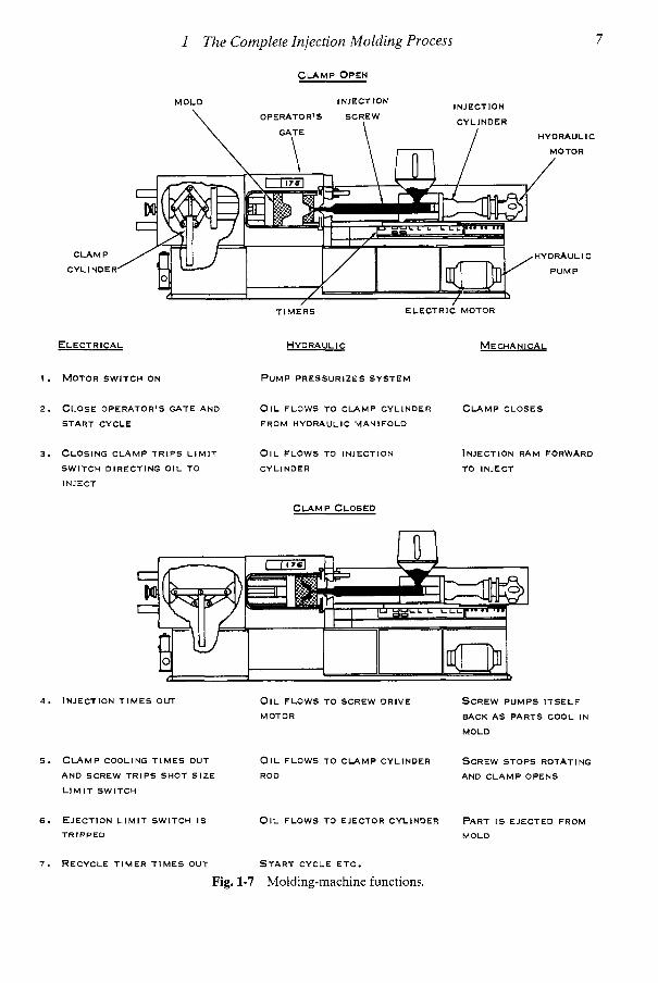
ELECTRICAL
1 . MOTOR SWITCH ON
2. CLOSE OPERATOR'S GATE AND
START CYCLE
3. CLOSING CLAMP TRIPS LIMIT
SWITCH DIRECTING O I L TO
INJECT
HYDRAULI c MECHANICAL
P U M P PRESSURIZES SYSTEM
OIL FLOWS TO CLAMP CYLINDER C L A M P CLOSES
FROM HYDRAULIC MANIFOLD
OIL FLOWS TO INJECTION
CYLINDER
INJECTION RAM FORWARD
TO INJECT
C L A M P CLOSED
4 . INJECTION T I M E S OUT
5 . C L A M P COOLING T I M E S OUT
AND SCREW TRIPS SHOT S I Z E
L I M I T SWITCH
OIL FLOWS TO SCREW DRIVE SCREW PUMPS ITSELF
MOTOR BACK A S PARTS COOL IN
MOLD
OIL FLOWS TO CLAMP CYLINDER SCREW STOPS ROTATING
ROD AND C L A M P OPENS
6. EJECTION L I M I T SWITCH I S OIL FLOWS TO EJECTOR CYLINDER PART I S EJECTED FROM
TRIPPED MOLD
7. RECYCLE T I M E R T I M E S OUT S T A R T CYCLE ETC.
Fig. 1-7 Molding-machine functions.

8
Resin Melt Index Mol. Wt. Distribution Additives
Density
1 The Complete Injection Molding Process
Process
F Pressure 4 Temperature
Cycle Mold & Process Design
Products Properties
I I I I
Fig. 1-8 Interrelation of product, resin, and process.
of heating-cooling cycles before appear- ance and/or properties are affected. Ther- mosets (TSs), upon their final heating [usually at least to 120°C (248"F)], be- come permanently insoluble and infusible. During heating they undergo a chemical (cross-linking) change. Certain plastics re- quire higher melt temperatures, some as high as 400°C (752°F) (see section on Recycling in Chap. 6).
Extensive compounding of different amounts and combinations of additives (colorants, flame retardants, heat and light stabilizers, etc.), fillers (calcium carbonate, etc.), and reinforcements (glass fibers, glass flakes, graphite fibers, whiskers, etc.) are used
with plastics. Compounding also embraces the mixing (alloying, blending, etc.) of two or more plastics that may be miscible or immiscible, with or without additives.
With TPs, the mold initially is kept at as low a temperature as possible, below the melting point of the plastic melt. This approach causes the injected hot melt to initiate surface freez- ing on the cavity wall, followed by formation of the solid product. After a sufficient cool- ing time, the mold opens and the part(s) are ejected. When processing TSs [from the in- jection unit (plasticizer)], the hot melt enter- ing the heated mold initially remains below the temperature that would cause premature solidification due to its exothermic reaction.
P R O C E S S P R O D U C T
Fig. 1-9 Simplified processing steps.

1 The Complete Injection Molding Process 9
1 Performance Requirements I
I Material Selection I
.;........;l=r;’ Ideal choiceiCompromise
Fig. 1-10 Flow diagram for setting up the selec- tion procedure.
After properly filling the cavity or cavities, the mold’s higher temperature causes the melt to undergo its final chemical cross- linking action resulting in solidification.
Morphology and Performance
The processability and performance of TPs, such as meeting product tolerance re- quirements and mechanical properties, are influenced by factors such as molecule size and weight, molecular distribution, and shapes or structures of individual molecules. TPs are formed by combining into long chains of molecules, or molecules with branches (lat- eral connections) to form complex molecular shapes. All these forms exist in either two or three dimensions, Because of their geome- try (morphology), some of these molecules can come closer together than others. These are identified as crystalline (such as PE, PP, and PA); the others are amorphous (such as PMMA, PS, SAN, and ABS). Morphology pertains to TPs but not TSs. When TSs are processed, their individual chain segments
scmw tJOzzle 2.25 in. dla.
16.000 wl
Mold injector -\
(Plasticator)
Fig. 1-11 Pressure-loading melt into the cavity.
CUREINMOLDCAW
PLAmQzING FORNEXTSHOT:
nBWMltlOWaafnmuruDI L Fig. 1-12 TQtALCYQEtlME Mechanical load profile.

10 I The Complete Injection Molding Process
MATERIAL
INJECTION
N ” -PLASTIC COOLING IN MOLD .
TRAVEL
TEMPERATURE PRESSURE
SHRINKAGE CCCCRS
30 sec 5 sec
FILLING RATE
Fig. 1-13 Example of an injection molding cycle.
TIME
are strongly bonded together during a chem- ical reaction that is irreversible.
Plastics are either truly homogeneous, amorphous solids or heterogeneous, semi- crystalline solids. There are no purely crys- talline plastics; so-called crystalline materials also contain different amounts of amorphous material. The term semicrystalline is techni- cally more accurate, but seldom used. Vari- ous methods of characterizing and evaluating
HIGH-QUALITY I MOLDED PARTS I 1 GOODMOLD 1 ADEQUATE MOLD
CLAMPING FORCE
I Receive and review product I I I
Complete preliminary appraisal
Assign deaign prlorlty
I Produce product I Fig. 1-15 Overall product approach.

1 The Complete Injection Molding Process 11
TOUGH
POLYPROPYLENE VINYL
BRITTLE
Note: With formulation changes (via addltlver, flllen, reln- lorcements. alloylng, etc.) porltlon 01 plastlc can moue practically any place in the "pie."
Fig. 1-16 Range of properties.
plastics are used, such as their molecu- lar weight distribution (MWD). A narrow MWD enhances the performance of plastic products. MWD affects melt flow behavior (Chap. 6).
Melt Flow and Rheology
Rheology is the science that deals with the deformation and flow of matter under various conditions. An example is plastic melt flow.
The rheology of plastics, particularly TPs, is complex but manageable. These materials combine the properties of an ideal viscous liquid (pure shear deformations) with those of an ideal elastic solid (pure elastic defor- mation). Plastics are therefore said to be vis- coelastic. The mechanical behavior of plastics is dominated by the viscoelastic parameters such as tensile strength, elongation at break, and rupture energy. The viscous attributes of melt flows are very important considerations during any processing system (see section on Molding Thin Walls in Chap. 7).
Viscosity is a material's resistance to vis- cous deformation (flow). Quantitatively it is expressed by the modulus of elasticity E (Chap. 12).
Plastics undergo non-Newtonian flow: the curve of pressure vs. flow rate for the melt is not a straight line. By contrast, the flow of water is nearly Newtonian.
Not only are there these two classes of deformation; there are also two modes in which deformation can be produced: simple shear and simple tension. The actual beha- vior during melting, as in a screw plasticator (injection unit), is extremely complex,
NATURAL GAS PETROLEUM COAL AGRICULTURE
v
I 1
ETHANE PROPANE BENZENE NAPHTHA BUTENE
\I 1
7 ETHYLENE STYRENE FORMALDEHYDE POLYOL ADIPATE PROPYLENE VINYL CHLORIDE CUMENE ACRYLIC 77 v 1
T? \I 1
77 v 1
TK? \I 1
POLYETHYLENE POLYSTYRENE ACETAL POLYCARBONATE POLYPROPYLENE POLYVINYLCHLORIDE NYLON
r \ EXTRUSION INJECTION BLOW CALENDER COATING
r n BUILDING PACKAGING TRANSPORTATION RECREATION
ELECTRICAL CONSUMER INDUSTRIAL
7
n PIPE APPLIANCE PACKAGING LUGGAGE MARINE SIGN TOY '
PRODUCTS SIDING COMMUNICATION ELECTRICAL MEDICAL AUTO TOOL - 1 I
Fig. 1-17 Raw materials to products.

12 1 The Complete Injection Molding Process
Tensile loud %+4
Resistance to
bending Mfm ).
+ik&&, Deflection, rig i di ty
*--\
Buckling
Fig. 1-18 Examples of mechanical tests.
displaying many types of shear-tension re- lationships. Together with the screw design, the deformation determines the pumping ef- ficiency of the plasticator and controls the re- lationship between output rate and pressure drop through the melt flow to solidification in the mold cavity(s).
Plasticating
Plasticating is the process that melts the plastics. Different methods are used. The most common are the single-stage (recip-
rocating screw) and the two-stage. In Fig. 1-19, (a) and (b) show the ram (also called plunger) systems used in the original IMMs since the 1870s, and now used mainly to pro- cess plastics with very little melt flow, such as ultrahigh-molecular-weight polyethylene. They use a piston, with or without a torpedo, for plastication. Part (c) shows the single- stage reciprocating screw plasticator, and (d) the two-stage screw plasticator.
There are different IMM operating de- signs in use: all-hydraulic, all-electrical, and hybrid (combination of hydraulic and electrical). Each design provides different

1 The Complete Injection Molding Process 13
- I I MOLD 4 E , i E , SINGLE-STAGE RAM INJECTION
MOLD
W SINGLE-STAGE OR RECIPROCATING SCREW MOLD
SCREW PLASTICATOR
W TWO-STAGE OR PREPLASTICKING SCREW MOLD
Fig. 1-19 Examples of different plasticating systems.
advantages such as reducing product weight (reducing plastic consumption), eliminat- ing or minimizing molded-in stresses, mold- ing extremely small to very large products, and/or improving performance. There are also IMMs that perform specialty molding operations. An example is the gas-injection molding machine (GIMM) systems. They ba- sically involve the injection of an inert gas, usually nitrogen, into the melt as it enters
the mold. The gas forms a series of inter- connecting hollow channels within the melt. The gas pressure at about 4,300 psi (30 MPa) is maintained through the cooling cycle. In effect the gas packs the plastic against the cavity (Chap. 15).
Another design is injection-compression molding, also called injection stamping or more often coining. It uses a compression type mold having a male plug that fits into

I 4 1 The Complete Injection Molding Process
Fig. 1-20 Sections of a screw.
a female cavity. After a short shot enters the mold (which has been previously opened and closed so that it is unpressurized), the stress-free melt is compressed to mold the finished product. Other systems include coin- jection, two-color injection molding, coun- terflow injection molding, multi-live injec- tion molding, oscillatory injection molding, reaction injection molding, liquid injection molding, foam injection molding, fusible- and soluble-core injection molding, tandem in- jection molding, injection blow molding, in- jection molding with rotation, continuous injection molding (Velcro strips, etc.), metal- plastic injection molding, and vacuum injec- tion molding (Chap. 15)
Screw Designs
The primary purpose for using a screw located in the plasticator barrel is to take advantage of its mixing action. The motion of the screw is controlled to keep the IMM’s process controls operating at their set points. The usual variation in melt temperature, melt uniformity, and melt output is kept to a mini-
mum prior to entering the mold. Heat is sup- plied by heater bands around the barrel and by the mixing action that occurs when the plastic is moved by the screw. Both conduc- tion heating and mechanical friction heating of the plastic occur during screw rotation. The different controls used during injection mold- ing, such as back pressure and screw rota- tional speed, influence the melt characteris- tics (Chap. 3).
Most IMMs use a single constant-pitch, metering-type screw for handling the plastics. The screw has three sections, for feed, melt- ing (transition), and metering (Fig. 1-20). The feed section, which is at the back end of the screw (where plastic first enters), can occupy from very little to 75% of the screw length, usually 50 to 75%. Its length essentially de- pends upon how much heat has to be added to the plastic that enters the hopper, where it may be preheated.
The melting (transition) section is where the softening of the plastic occurs; the plastic is transformed into a continuous melt. It can occupy from 5 to 50% of the screw length. This section, usually called the compression zone, has to be sufficiently long to make

1 The Complete Injection Molding Process 15
sure that the plastic is melted. A straight compression-type screw is one having no feed or metering section. For certain plastics, par- ticularly TSs, there tends to be no compres- sion zone, since overheating and solidifica- tion of the melt could occur between the screw and barrel.
In the metering section, the plastic is smeared and sheared to give the melt its fi- nal uniform composition and temperature for delivery to the mold. As high shear action will tend to increase the melt’s temperature, the length of the metering section is depen- dent upon the plastic’s heat sensitivity and whether any additional mixing is required. For certain heat-sensitive plastics very little or no metering action can be tolerated. For other plastics it averages about 20 to 25% of the screw length. Both the feed and meter- ing sections usually have a constant cross sec- tion (zero compression ratio). However, the depth of flight in the feed section is greater than that in the metering section. The screw’s compression ratio can be determined by di- viding the flight depth in the feed section by that in the metering section. Depending on the plastic processed, ratios usually range from 0 to 4.
Molds
The mold is the most important part of the IMM. It is a controllable, complex, and ex- pensive device. If not properly designed, op- erated, handled, and maintained, its opera- tion will be a costly and inefficient.
Under pressure, hot melt moves rapidly through the mold. During the injection into the mold, air in the cavity or cavities is re-
leased to prevent melt burning and the for- mation of voids in the product. With TPs, temperature-controlled water (with ethylene glycol if the water has to operate below its freezing point) circulates in the mold to re- move heat; with TSs, electrical heaters are usually used within the mold to provide the additional heat required to solidify the plastic melt in the cavity.
The mold basically consists of a sprue, a runner, a cavity gate, and a cavity. The sprue is the channel located in the stationary platen that transports the melt from the plastica- tor nozzle to the runner. In turn, melt flows through the runner and gate and into the cav- ity. With a single-cavity mold, usually no run- ner is used, so melt goes from the sprue to the gate.
Different runner systems are in use to meet different processing requirements. The most popular are cold and hot runners. With a TP cold runner, the melt flowing from the sprue to the gate solidifies by the cooling action of the mold as the melt in the cavity or cavities solidifies. With a TP hot runner the sprue to the gate is insulated from the chilled cavity or cavities and remains hot, so that the melt never cools; the next shot starts from the gate, rather than from the nozzle as in a cold run- ner. With a TS hot runner, the melt in the runner solidifies. The TS cold runner keeps the plastic melted by using a cooled insulated manifold; its next shot starts from the gate, rather than from the nozzle as in a TP hot runner.
Molds are provided with different means, such as sliders, unscrewing devices, undercuts (Fig. 1-21), and knockout systems, to eject products as well as solidified runners at the proper time. These basic operations in turn
Nominal thickness should be maintained throughout part
deeper hole intersecting side walls
Fig. 1-21 Methods of molding holes or openings in side walls without undercutting mold movements.

16 1 The Complete Injection Molding Process
DEPTH OF DRAW !-L DIMENSION DIFFERENCE
Fig. 1-22 Example of mold-cavity draft angle re- quired to ensure removal of molded product dur- ing its mold ejection action.
require control of various parameters such as fill time and hold pressure (Chap. 4).
To simplify molding, whenever possible one should design the product with fea- tures that simplify the mold-cavity melt filling operation. Many such features can improve the product’s performance and/or reduce cost. An example is choosing the mold-cavity draft angle according to the plastic being processed, tolerance requirements, etc. (Fig. 1-22). Figure 1-23 shows a situation where it is possible to eliminate or significantly re- duce shrinkage, sink marks, and other defects (Chap. 8).
Processing
Processing steps are summarized in Figs. 1-9, 1-10, and 1-24 to 1-27. Different ma- chine requirements and material conditions are considered in choosing the most efficient injection molding process. It is important to understand and properly operate the basic IMM as well as its auxiliary equipment. In particular, in practically all operations the screws must not be damaged or worn and the plastic must be properly dried. Special dryers and/or vented barrels are required for drying hygroscopic TP materials such as PC, PMMA, PUR, and PET (Chap. 10).
Use of TP regrind may have little effect on product performance (appearance, color, strength, etc.). However, reduction in perfor- mance can occur with certain TPs after even one passage through the IMM. Granulated TSs cannot be remelted but can be used as additives or fillers in plastics.
Many TPs can be recycled indefinitely by granulating scrap, defective products, and so on. During these cycles, however, the plas- tic develops a “time-to-heat” history or res- idence time. This phenomenon can signifi- cantly compromise processing advantages
POOR DESIGN
SINK MARKS
SUGGESTED ALTERNATIVES
I
CORE FROM BOTH SIDES IF POSSIBLE
v2 t
MATCH OUTSIDE CONFIGURATION TO INSIDE CORES
POOR RECTANGULAR PART WITH ROUND HOLES
Fig. 1-23 Example of coring in molds to eliminate or reduce shrinkage and sink marks.

1 The Complete Injection Molding Process
Fig. 1-24 Relationship between manufacturing process and properties of products.
Bulk density
Tablet density Tablet height
Melt flow behavior Curing characteristic Water content
Shrinkage characteristic Water content Stickiness (adhesion)
Feeding ease I Feeding accurcy
I ~~ ~
Pre-heating
Process: Compression molding transfer molding injection molding
pre-heating (temperature, time) mold filling (time, pressure) curing (temperature, time)
Dimensional stability Demoldlng behavior
Mold life Machine wear
Fig. 1-25 Processing behavior.
PROCESS ANALYSIS t
PRODUCT PARAMETERS REQUIREMENTS
FILLING PHASE FOLLOW-UP
PROCESS MODEL
INTERFERENCE MAGNITUDES
PROCESS COMPUTER FINAL MACHINE SEllINGS WITH
OPERATING RANGES MACHINE PARAMETER
CLOSEDLOOP HGgtH 1 I U I I
Fig. 1-26 Process control model.
17

18 1 The Complete Injection Molding Process
Preimpregnated
Post impregnation
Fig. 1-27 Processing steps via a fishbone diagram.
and properties, requiring compensation in the product design or process setup, and/or material modification by incorporating addi- tives, fillers, and/or reinforcements.
For all types of plastics, injection molding troubleshooting guides have been written to allow fast corrective action when products do not meet their performance requirements. Examples of errors in the mold and product design with possible negative consequences during processing and/or product perfor- mance are presented throughout this book. Troubleshooting guides can be incorporated in process control systems (Chap. 11). An ex- ample is checking dryer performance as sum- marized in Table 1.1.
Process Controls
Proper injection of plastic melt into the mold is influenced by several process control conditions (Chap. 7). Any one or combina- tion of these can affect various performance parameters, such as the rate of which the raw
material is fed into the IMM (Fig. 1-28), flow of melt, packing of mold cavity or cavities and cycle time, which in turn affect product performance (Chap. 8). As an example, pa- rameters that influence product tolerances in- volve (1) product design, (2) plastics used, (3) mold design, (4) IMM capability, and ( 5 ) molding cycle time.
Different types of machine process con- trols (PCs) can be used to meet different re- quirements based on the molder’s needs. PC systems range from simple monitors (alarm buzzers, flashing lights, etc.) to very sophisti- cated program controllers [personal comput- ers (PCs) interrelate different IMM functions and melt process variables]. (Note that PC has two meanings; see Appendix 1, Abbrevi- ations.)
Knowledge of the machine and plastic ca- pabilities is needed before an intelligent PC program can be developed (Chap. 9). The use of PC or SPC (statistical PC) software requires continual study of the endless new computer technology as it applies to basically melting plastic (Chap. 13).

1 The Complete Injection Molding Process
Table 1-1 Trouble shooting dehumidifier dryer performance
19
Symptom Possible Cause(s) Cure
1. Cannot attain desired air inlet temperature.
Heater failure.
Hose leakages and excessive length on air inlet side.
Line, hopper, or filter blockage.
2. Dewpoint as measured at air inlet to the hopper is unacceptable. line fuses.
Loss of regeneration heaters in one or both beds or
Loss of timer or clock motor ability to switch from one head to the other, Le., continuous operation on only one desiccant bed.
Desiccant has deteriorated or been contaminated.
Loss of power to one or both desiccant beds.
3. Airflow low or nonexistent.
Fan motor burned out. Loose fan on motor shaft. Clogged filter(s). Restricted or collapsed
Blower motor is reversed. air lines.
Check process air or afterheaters- regeneration heaters play no part in this aspect of operation.
Locate and repair-if the hose is old and brittle, replace. Shorten all hose to minimum lengths.
Check for collapsed or pinched lines, valves that are closed (some makes have airflow valves located on the air inlet side of the hopper). Filters should be changed or cleaned frequently- a good trial period is every four weeks until experience dictates a shorter or longer period.
These can be checked with a voltmeter at the control panel.
Check clock motor for movement by observing either function indicators or valve-shifting mechanisms. Note that loss of regeneration heaters may occur if the clock motor or shifting mechanism malfunctions.
Most manufacturers suggest checking the desiccant annually and replacing when it does not meet test criteria. Typically two to three years is a reasonable interval, depending upon the severity of service.
During regeneration cycle, exterior of the desiccant bed should be hot to touch. Check contacts on relays or printed circuit board for flaws; check line fuses if so equipped.
Replace. Tighten. Change. Correct and relieve restrictions.
Use of a pressure gauge or flowmeter is suggested. Proper rotation is that at which the highest flow is indicated.

20 I The Complete Injection Molding Process
4 \
Fig. 1-28 Hopper feed control unit.
Control Guides
Adequate PC and its associated instrumen- tation are essential for product quality con- trol (QC). The goal in some cases is precise adherence to a control point. In other cases, maintaining the temperature within compar- atively small range is all that is necessary for effortless control (of temperature, time, pressure, melt flow, rate, etc.) that will pro- duce the desired results (Chaps. 7,9, and 13).
Regardless of the type of controls available, the processor setting up a machine uses a sys- tematic approach that should be outlined in the machine and/or control operating man- uals. Once the machine is operating, the op- erator methodically targets one change at a time to achieve maximum injection molding efficiency.
With injection molding, as with all types of plastics processing, troubleshooting guides are established to take fast corrective action

1 The Complete Injection Molding Process 21
when parts do not meet their performance re- quirements (Chap. 11). This problem-solving approach fits into the overall PC and fabri- cating interface.
Control systems for units with complex processes such as injection molding are be- coming increasingly common. Such systems consist mostly of control chains and circuitry that are often coupled in their functions, as well as the corresponding exchange of data. In a broad sense, the control systems serve the purpose of cost reduction by monitoring quality and establishing high line efficiency, in addition to the reduction of raw mate- rial consumption and labor costs. A control system contributes in different ways, partic- ularly in controlling the flow of plastic melt. It can function by itself and fulfill the duties assigned to it, often resulting in product im- provement.
Since the 1960s, a procedure to influence important properties of the final product has been developed. The solutions, when intro- duced into practice, served first of all to improve the product line in different manu- facturing plants. However, initially these sys- tems established themselves in only relatively small niches of the commercial market. Later many more came aboard.
The use of flexibly automated injection molding controls and systems definitely de- pends on the tasks the machine has to perform and the production sequences re- quired. Automation is one possibility for putting in-house aims into practice and/or meeting market-dictated demands such as (1) production-cost reduction, (2) short job processing time, (3) low expenditure on setup, (4) greatest possible preparedness for meeting delivery dates, (5) large product range, and (6) improved delivery consistency.
In order to utilize the advantages of flexi- bly automated injection molding cells, a con- siderably larger capital investment is nec- essary than with other choices of systems, which are less automated and flexible. This increases the investment risk, so that the question of the profitability of such systems becomes more urgent. The following are examples of productivity-increasing effects: (1) an increase in the annual utilization time,
(2) an increase in annual production vol- ume, (3) a reduction of demolding time, and (4) a shortening of transit time if additional activities can be carried out within the pro- grammed cycle time.
The profitability of a flexibly automated injection molding plant is influenced by (1) increased capital cost, (2) reduced per- sonnel costs due to fewer personnel required, and (3) changes in energy costs and the mold-cost structure. With automation, new goals can be met through plant flexibility, such as (1) improved delivery consistency, (2) greatest possible preparedness for meet- ing delivery dates, (3) large range of products, and (4) short job processing time. There are also quality-related effects that result in im- proved quality assurance and a reduced num- ber of rejects. Work environment changes oc- cur in (1) psychological and physical stresses on staff, (2) qualification requirements from staff, (3) social welfare of staff employed on the injection molding machine, and (4) the ac- cident risk situation. An evaluation of the uti- lization efficiency serves for assessing the cri- teria that cannot be quantified in monetary terms. An established utilization efficiency value can be taken as a decision aid, which in conjunction with the investment calculation will allow a better selection of alternatives under consideration.
Art of Processing
Processing of plastic is an art of detail. The more you pay attention to details, the fewer hassles you will get from the process. If a pro- cess has been running well, it will continue running well unless a change occurs. Correct the problem; do not compensate. That may not be an easy task, but understanding your equipment, material, environment, and peo- ple can make it possible.
Fine Tuning
A computer-integrated injection molding (CIIM) system makes it possible to target for: (1) approaching a completely automated

22 1 The Complete Injection Molding Process
injection molding system, (2) simultaneously achieving high quality (zero defects), ( 3 ) increasing productivity, and (4) minimizing cost. It does this in several ways, basically by enabling the molder to fine-tune all the re- lationships that exist among the many ma- chine settings and properties of the plastic melt. These systems, when properly used, readily adapt to enhanced processing capa- bilities.
Once processing variables (machine and plastic) are optimized through computer sim- ulation (rather than the usual trial-and-error method), these values are entered in com- puter programs in the form of a rather large number of machine settings. Establishing the initial settings during startup can be inher- ently complex and time-consuming. Regard- less, the many benefits of these systems are well recognized and accepted. However, it is evident that self-regulation of injection molding can be effective only when the de- sign of the product and the mold are opti- mized with the correct processing conditions. Otherwise, a self-regulating IMM is confused and can issue conflicting instructions. The re- sults can be disastrous, including damage to the machine and/or the mold as well as safety hazards. Therefore, the efficient utilization of microprocessor control systems depends on the success of utilizing correct and opti- mum programs with knowledgeable people (Chap. 9). On the horizon is the potential for fuzzy control to provide an important aid to optimizing process control performance. As reviewed in Chap. 7, fuzzy logic, since its in- ception in 1981, has striven with increasing success to mimic the control actions of a hu- man operator.
Molding Operations
The following modes of operations typify injection molding operations.
functions repeat. The IMM stops only in the event of a malfunction or if it is man- ually interrupted. Machinery and mecha- nisms are self-controlled so that manual in- put is not necessary during operation. The continuing development of more sophisti- cated processing equipment in turn allows the development of more integrated process- ing equipment. This action results in many improvements, such as (1) increased operat- ing efficiency through reducing scrap and/or rejects, (2) improved quality through uni- form, repeatable manufacturing procedures, (3) decision making and record keeping by converting data to information, (4) access to manufacturing information by supervisors and management, and ( 5 ) process control and process management.
Automation level The automation level is the degree to which a process operates au- tomatically. The choice of level must take into account the ability of the system to di- agnose problems in operation, the ability of the system to recover from error or fault, the ability of a system to start up and shut down without human intervention, and the like.
Automated vision Vision automation provides a means to achieve automatic equipment operation by adaptive part re- moval. It provides the capability of detecting a variety of part problems or defects by critical part inspection.
Semiautomatic
A semiautomatic machine will perform a complete cycle of programmed molding func- tions automatically and then stop. It will then require an operator to start another cycle manually.
Manual Automatic
A machine operating automatically will perform a molding cycle where programmed
It is an operation in which each function and the timing of each function is controlled manually by an operator.

1 The Complete Injection Molding Process 23
Primary
Identifies the main molding operation equipment to fabricate products namely the injection molding machine (Chap. 2).
Secondary
After fabricating (primary) molded prod- ucts, secondary operations may be required to produce the final finished product. These operations can occur online or offline. They include any one or a combination of opera- tions such as the following: annealing (to re- lieve or remove residual stresses and strains), postcuring (to improve performance); plat- ing; joining and assembling (adhesive, ultra- sonic welding, vibration welding, heat weld- ing, etc.); drilling; cutting; finishing; polishing; labeling; and decorating/printing. The type of operation to be used depends on the type of plastic used. As an example, decorating or bonding certain plastics is easy, while others require special surface treatments for those purposes (Chap. 10).
Purchasing and Handling Plastics
On the average, raw materials and their handling services incur at least half of the costs in plastic injection molding. Wages, util- ities, overhead, and capital equipment costs account for the rest. All costs are important to evaluate and justify. As an example in a high- production injection molding line, equipment costs may represent less than 5% of the to- tal cost of production. Nevertheless, economy and rationality are worthy aims when pur- chasing equipment (Chap. 14).
It is obviously important to at least pur- chase the raw materials at favorable prices. One must see that they are delivered punctu- ally bust in time (JIT) or otherwise], provide the required handling systems, use as little as possible (design minimum wall thicknesses of products, do not overpack in cavity, etc.), and ensure that material conforms to the required specification(s). Action is usually required to check materials received.
There are a wide variety of tasks requir- ing the use of auxiliary equipment that in- cludes warehousing to handling materials. As reviewed throughout this book, performance requirements are important for the successful operation of the IMM and auxiliary equip- ment. They usually require raw materials, additives, spare parts, molds, tools, molded products, and so on to be stored and handled safely and economically. Various systems are available to meet different needs in ware- housing. They can implement schemes for integrating the inward and outward flow of goods, order picking and transportation, fac- tory administration, and process control for warehousing.
Processors
There are basically three types of proces- sor: captive, custom, and proprietary.
Cap five
Captive processors, also called captive fab- ricators, are in-house facilities of companies that have acquired plastics processing equip- ment to make parts they need for the prod- uct they manufacture. For example, a electri- cal connector manufacturer may acquire an IMM to produce connectors.
Generally speaking, these manufacturers will install a captive operation when their component requirements are large enough to make it economical or they have a secret product or process. Some manufacturers that run their own plastics fabricating lines will nevertheless place a portion of their require- ments with outside vendors to keep their own capital investment down, to avoid internal single-source supply, to maintain contact with the outside world and the pricing intelligence it provides, and so on. The vendor may be a custom processor or have a captive operation for their requirements. A problem with some captive operations is that they do not keep up with new developments, some of which may be critical.

24 1 The Complete Injection Molding Process
Custom
The custom processor’s facilities, like those in the metal-working field, may be called job shops. They process plastics into products or components used in other industries. For example, a manufacturer of injection-molded bottles may retain a custom processor to mold preforms. Custom processors typically have a close relationship with the companies for whom they work. They may be involved (to varying degrees) in the design of the product and the mold, they may have a voice in ma- terial selection, and in general they assume responsibility for the work they turn out.
Custom-contract There is a subgroup of custom processors known as contract fabricators. They have little involvement in the business of their customers. In effect, they just sell machine time.
checklist. Times on cutting tools include ba- sics in equipment and their control opera- tions (2000 h), lathe (800), milling (lOOO), grinder ( lOOO), chrome plating (loo), jig bore (700), honing (loo), EDM (300), inspection tools (loo), and so on.
The list of postsecondary schools devot- ing a significant portion of their funds to moldmaking and related programs is growing rapidly. As the industry continues to review the labor pool and come up short, and as un- dergraduate institutions fight over a shrink- ing market, education-and-industry partner- ing is increasing in urgency. As an example, the Moraine Park Technical College of Southeastern Wisconsin, an internationally known facility of the machine tooling indus- try, is a well-established school with a re- put able program that, in conjunction with other area schools, has provided local indus- tries a highly trained workforce for decades (410).
Proprietary Processor Certifications
A proprietary operation is one where the processor makes a product for sale directly to the public or to other companies. It usually has its own trade name.
Training Programs
Various training programs and seminars for processors and mold manufacturers are available worldwide. Information concerning processors’ training programs is reviewed in Chaps. 2,9, and 12 as well as other chapters. A tooling example is the apprentice training programs of the USA Tooling & Manufactur- ing Association (Park Ridge, IL). Their ef- fective programs are based on well-planned services that involve properly supervised on- the-job training and classroom instruction. Such programs start with the development of a policy manual. One of TMA’s most effec- tive trainers is Northwestern Tool and Die Manufacturing Corp. (Skokie, IL).
Each training module includes a practical experience checklist, material checklist, prac- tical experience record of hours, and safety
National skills certification programs by different organizations are in existence worldwide to certify the skills and knowledge of plastics-industry processor machine oper- ators. Action by the different organizations continues to provide methods of improving these programs. As an example, the Society of Plastics Industry’s Industries National Cer- tification in Plastics (NCP) program has as its purposes: (1) to identify job-related knowl- edge, skills, and abilities, ( 2 ) to establish a productive performance standard, (3) to assess and recognize employees who meet the standard, and (4) to promote careers in the plastics industries. The examination in- cludes basic process control; prevention and corrective action on primary and secondary equipment; handling, storage, packaging, and delivery of plastic materials; quality assur- ance; safety; tools and equipment; and gen- eral knowledge.
The Society of Plastics Engineers’ Plas- tics Technology Certification was for plas- tics professionals who have the knowledge and ability to apply mathematics, the physical

1 The Complete Injection Molding Process 25
SERVICES
Consultants- Designers -Process Engineering -ISO -Education -Legal- Accounllng -Flnanclal- Marketing -Advertising -PublIshing -Training
.t
-"+
+
t~
I Household I Business I Government I Export I
Fig. 1-29 The plastics industry.
26 1 The Complete Injection Molding Process
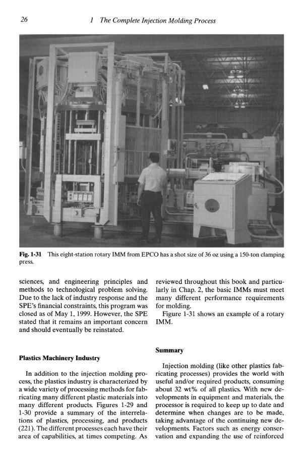
Fig. 1-31 This eight-station rotary IMM from EPCO has a shot size of 36 oz using a 150-ton clamping press.
sciences, and engineering principles and methods to technological problem solving. Due to the lack of industry response and the SPE's financial constraints, this program was closed as of May 1,1999. However, the SPE stated that it remains an important concern and should eventually be reinstated.
reviewed throughout this book and particu- larly in Chap. 2, the basic IMMs must meet many different performance requirements for molding.
Figure 1-31 shows an example of a rotary IMM.
Summary Plastics Machinery Industry
In addition to the injection molding pro- cess, the plastics industry is characterized by a wide variety of processing methods for fab- ricating many different plastic materials into many different products. Figures 1-29 and 1-30 provide a summary of the interrela- tions of plastics, processing, and products (221). The different processes each have their area of capabilities, at times competing. As
Injection molding (like other plastics fab- ricating processes) provides the world with useful and/or required products, consuming about 32 wt% of all plastics. With new de- velopments in equipment and materials, the processor is required to keep up to date and determine when changes are to be made, taking advantage of the continuing new de- velopments. Factors such as energy conser- vation and expanding the use of reinforced

1 The Complete Injection Molding Process 27
plastics (RPs) provide more potential pro- duct growth.
Already injection molding is the highest- volume method for RPs processed using milled or short glass fibers. Long-fiber mate- rials such as bulk molding compounds have been used for about half a century using stuffer-ram feeders with ram and/or screw IMM plasticators. With in-mold layups of re- inforcements, RPs’ high-performance direc- tional properties are achievable (1,18).
Although considerable talent can be brought to bear on processing and engi- neering aspects, selecting the best process technique and plastic material also involves economic and legal concerns (Chaps. 14, 16). Cost problems are particularly acute when the technology that will be employed is not fully understood and much of the cost analysis is based on historical data, past experience, and individual accounting
practices not properly updated. A technical cost modeling (TCM) system can be used for analyzing the economics of alternative injection molding methods and other pro- cesses without the prohibitive economic bur- den of trial-and-error innovation and process optimization. Cost variations are analyzed by setting up differing (1) performance require- ments, (2) part design, (3) plastic selection, (4) hardware selection, and ( 5 ) testing, quality control, and troubleshooting factors (Chap. 14).
Any design choice for injection molding (or any other process) is a balance between gains and losses. A gain in one area can com- promise product performance, cost, and/or other factors. However, with people work- ing smarter, using the FALL0 approach (Fig. 1-l), analyzing failures or limitations, and innovating, you can expand your target and meet future product requirements.


