Embed Size (px)
Citation preview

Dear Customer
Please find enclosed Amendment 8, effective 10 October 2011, to the Compliance Document for Clause G12 Water Supplies of the New Zealand Building Code.
Section Old G12 October 2011 Amendments to G12
Title pages Remove title page and document history Replace with new title page and document history
References Remove pages 7–10 Replace with new pages 7–10
Definitions Remove page 11/12 Replace with new page 11/12
G12/AS1 Remove pages 21–24, 41/42 Replace with new pages 21–24, 41/42
G12/AS2 Remove page 43/44 Replace with new page 43/44
ARCHIVED

ARCHIVED

Compliance Document for New Zealand Building Code Clause G12Water Supplies – Third EditionPrepared by the Department of Building and Housing
This Compliance Document is prepared by the Department of Building and Housing. The Department of Building and Housing is a Government Department established under the State Sector Act 1988.
Enquiries about the content of this document should be directed to:
Department of Building and HousingPO Box 10-729, Wellington.Telephone 0800 242 243Fax 04 494 0290 Email: [email protected]
Compliance Documents are available from www.dbh.govt.nz
© Department of Building and Housing 2011
This Compliance Document is protected by Crown copyright, unless indicated otherwise. The Department of Building and Housing administers the copyright in this document. You may use and reproduce this document for your personal use or for the purposes of your business provided you reproduce the document accurately and not in an inappropriate or misleading context. You may not distribute this document to others or reproduce it for sale or profit.
The Department of Building and Housing owns or has licences to use all images and trademarks in this document. You must not use or reproduce images and trademarks featured in this document for any purpose (except as part of an accurate reproduction of this document) unless you first obtain the written permission of the Department of Building and Housing.
ARCHIVED
Status of Compliance Documents
Compliance Documents are prepared by the Department of Building and Housing in accordance with section 22 of the Building Act 2004. A Compliance Document is for use in establishing compliance with the New Zealand Building Code.
A person who complies with a Compliance Document will be treated as having complied with the provisions of the Building Code to which the Compliance Document relates. However, a Compliance Document is only one method of complying with the Building Code. There may be alternative ways to comply.
Users should make themselves familiar with the preface to the New Zealand Building Code Handbook, which describes the status of Compliance Documents and explains alternative methods of achieving compliance.
Defined words (italicised in the text) and classified uses are explained in Clause A1 and A2 of the Building Code and in the Definitions at the start of this Compliance Document.
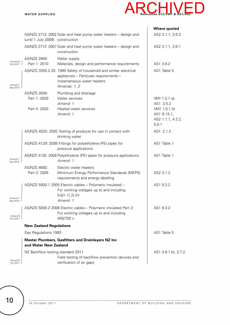
G12: Document History
Date Alterations
First published July 1992
Amendment 1 September 1993 pp. vi–viii, References p. ix, Definitions p. 15, Table 4 p. 16, 4.5.1, 4.5.3
p. 19, 5.2.2 b) p. 22, Table 7 p. 26, Index
Amendment 2 19 August 1994 pp. i and ii, Document History p. v, Contents p. viii, References p. 3, 2.2.1 e)
p. 6, 2.6, 2.6.1 p. 19, 4.13.1, 4.14, 4.14.1 p. 26, 29, Index
Amendment 3 1 December 1995 p. ii, Document History pp. vi–viii, References
p. 5, Table 1 p. 6, 2.5.2
Second edition published July 2001
Effective from 1 October 2001
Document revised – Second edition issued
Amendment 4 6 January 2002 pp. 3–5 Code Clause G12
Amendment 5 25 February 2004 p. 2, Document History p.7, Contents pp. 9–11 References
pp. 23-38, 3.7.1, 3.7.4, 4.1, 6.2.1, 6.3.2–6.15, Figure 13 pp. 43-45 Index
Amendment 6 23 June 2007 p. 2, Document History, Status pp. 9 and 11, References
p. 13, Definitions p. 15, VM1 1.0.1
Third edition published October 2007
Effective from 1 December 2007
Document revised – Third edition issued
G12/AS1 amended:p. 27, Table 5 p. 32, 6.5.1p. 35, 6.9, 6.10 p. 36, 6.11.5
p. 37, 6.14.3p. 38, 6.15 (deleted)p. 40, 7.5.2 New Acceptable Solution G12/AS2 included
Amendment 7 Published 30 June 2010 Effective from 30 September 2010
p. 2, Document History, Status pp. 3 and 4, Code Clause G12 pp. 7–10, References
p. 17, G12/AS1 2.1.2, Table 1 p. 27, G12/AS1 Table 5 p. 32, G12/AS1 Table 6
p. 41, G12/AS1 9.3.2
Amendment 8 10 October 2011 p. 2, Document History, Status pp. 7–10, References p.12, Definitions p. 21, G12/AS1 3.6.1
p. 23, G12/AS1 3.7.2 p. 41, G12/AS1 9.3.2 p. 43, G12/AS2 1.1.1
Note: Page numbers relate to the document at the time of Amendment and may not match page numbers in current document.
Document Status
The most recent version of this document, as detailed in the Document History, is approved by the Chief Executive of the Department of Building and Housing. It is effective from 10 October 2011 and supersedes all previous versions of this document.
People using this Compliance Document should check for amendments on a regular basis. The Department of Building and Housing may amend any part of any Compliance Document at any time. Up-to-date versions of Compliance Documents are available from www.dbh.govt.nz
ARCHIVED

�
w At e r S u p p l i e S
D E PA R T M E N T O F B U I L D I N G A N D H O U S I N G 1 0 O c t o b e r 2 0 1 1
For the purposes of New Zealand Building Code (NZBC) compliance, the Standards and documents referenced in this Compliance Document (primary reference documents) must be the editions, along with their specific amendments, listed below. Where these primary reference documents refer to other Standards or documents (secondary reference documents), which in turn may also refer to other Standards or documents, and so on (lower-order reference documents), then the version in effect at the date of publication of this Compliance Document must be used.
where quoted
Standards New Zealand
NZS/BS 1387: Specification for screwed and socketed steel tubes AS1 Table 1 1985 and tubulars and for plain end steel tubes suitable for welding or screwing to BS 21 pipe threads Amend: 1
NZS 3501: 1976 Specification for copper tubes for water, gas, AS1 Table 1 and sanitation Amends: 1, 2, 3
NZS 3604: 2011 Timber framed buildings AS2 1.1.1
NZS 3604: 1999 Timber framed buildings AS2 1.1.1
NZS 3604: 1990 Timber framed buildings AS2 1.1.1
NZS 4203:1992 Code of Practice for general structural design AS2 1.1.1 and design loadings for buildings
NZS 4602: 1988 Low pressure copper thermal storage AS1 Table 5 electric water heaters Amend: 1
NZS 4603: 1985 Installation of low pressure thermal storage AS1 6.9.1, 6.11.5 electric water heaters with copper cylinders (open-vented systems) Amend: 1
NZS 4606: Storage water heaters Part 1: 1989 General requirements AS1 Table 5 Amends: 1, 2, 3Part 2: 1989 Specific requirements for water heaters with AS1 Table 5 single shells Amend: A Part 3: 1992 Specific requirements for water heaters with AS1 Table 5 composite shells Amend: A
NZS 4607: 1989 Installation of thermal storage electric water AS1 6.10.1 heaters: valve-vented systems
NZS 4608: 1992 Control valves for hot water systems AS1 Table 6
NZS 4613: 1986 Domestic solar water heaters AS2 3.1.1, 7.2.3
ReferencesG12/VM1&AS1/AS2
References
Amend 7Sep 2010
Amend 8Oct 2011
Amend 8Oct 2011
Amend 8Oct 2011
ARCHIVED

� 1 0 O c t o b e r 2 0 1 1 D E PA R T M E N T O F B U I L D I N G A N D H O U S I N G
w At e r S u p p l i e S
NZS 4614: 1986 Installation of domestic solar hot water AS2 4.2.2 heating systems
NZS 4617: 1989 Tempering (3- port mixing) valves AS1 6.14.2 b)
NZS 5807: 1980 Code of practice for industrial identification by colour, wording or other coding Part 2: 1980 Identification of contents of piping, conduit AS1 4.3.1 and ducts Amends: 1, 2
NZS 6214: 1988 Thermostats and thermal cutouts for domestic AS1 6.5.1 thermal storage electric water heaters (alternating current only)
NZS 7601: 1978 Specification for polyethylene pipe (Type 3) for AS1 Table 1 cold water services
NZS 7602: 1977 Specification for polyethylene pipe (Type 5) for AS1 Table 1 cold water services Amend: 1
NZS 7610: 1991 Specification for blue polyethylene pipes up to AS1 Table 1 nominal size 63 for below ground use for potable water Amends: 1, 2, 3
British Standards institution
BS EN 1490: 2000 Building valves. Combined temperature and AS1 Table 6 pressure relief valves. Tests and requirements.
BS EN 1491: 2000 Building valves. Expansion valves. AS1 Table 6 Tests and requirements
BS EN 1567: 1999 Building valves. Water pressure reducing valves AS1 Table 6 and combination water reducing valves. Requirements and tests.
BS 6920 Suitability of non-metallic products for use in contact with water intended for human consumption with regard to their effect on the quality of the water Part 1: 2000 Specification AS1 2.1.2 Part 2: 2000 Methods of tests AS1 2.1.2 Part 3: 2000 High temperature tests AS1 2.1.2
ReferencesG12/VM1&AS1/AS2
Amend 7Sep 2010
where quoted
Amend 7Sep 2010
Amend 7Sep 2010
Amend 7Sep 2010
Amend 8Oct 2011
ARCHIVED

�
w At e r S u p p l i e S
D E PA R T M E N T O F B U I L D I N G A N D H O U S I N G 1 0 O c t o b e r 2 0 1 1
Standards Australia
AS 1308: 1987 Electric water heaters – Thermostats and AS1 6.5.1 thermal cut-outs Amend: 1
AS 1357: Water valves for use with unvented water heaters Part 1: 2009 Protection valves AS1 Table 6 Amend: 1, 2 Part 2: 2005 Control valves AS1 6.14.2 b), Amend: 1, 2 Table 6
AS 2845: Water supply – Mechanical backflow prevention devices Part 3: 1993 Field testing and maintenance AS1 3.6.1 b), Amend: 1 3.7.2
Australia/New Zealand Standards
AS/NZS 1170: Structural Design Actions Part 0: 2002 General principles AS2 1.1.1 Amend: 1, 2 and 4 Part 1: 2002 Permanent, imposed and other actions AS2 1.1.1 Amend: 1 Part 2: 2002 Wind Actions AS2 1.1.1 Amend: 1 Part 3: 2003 Snow and ice actions AS2 1.1.1 Amend: 1
NZS 1170: AS2 1.1.1 Part 5: 2004 Earthquake design actions – New Zealand
AS/NZS 1477: 2006 PVC pipes and fittings for pressure applications AS1 Table 1 Amend: 1
AS/NZS 2032: 2006 Installation of PVC pipe systems AS1 7.4.1, 7.5.2 Amend: 1
AS/NZS 2642: Polybutylene pipe systems Part 1: 2007 Polybutylene (PB) pipe extrusion compounds AS1 Table 1 Part 2: 2008 Polybutylene (PB) pipe for hot and cold AS1 Table 1 water applications Part 3: 2008 Mechanical jointing fittings for use with AS1 Table 1 polybutylene (PB) pipes for hot and cold water applications Amend: 1
ReferencesG12/VM1&AS1/AS2
where quoted
Amend 7Sep 2010
Amend 7Sep 2010
Amend 7Sep 2010
Amend 8Oct 2011
Amend 8Oct 2011
Amend 8Oct 2011
Amend 8Oct 2011
ARCHIVED
AS/NZS 2712: 2002 Solar and heat pump water heaters – design and AS2 3.1.1, 3.6.2 (until 1 July 2009) construction
AS/NZS 2712: 2007 Solar and heat pump water heaters – design and AS2 3.1.1, 3.6.1 construction
AS/NZS 2845: Water supply Part 1: 2010 Materials, design and performance requirements AS1 3.6.2
AS/NZS 3350.2.35: 1999 Safety of household and similar electrical AS1 Table 5 appliances – Particular requirements – Instantaneous water heaters Amends: 1, 2
AS/NZS 3500: Plumbing and drainage Part 1: 2003 Water services VM1 1.0.1 a), Amend: 1 AS1 3.5.2 Part 4: 2003 Heated water services VM1 1.0.1 b) Amend: 1 AS1 6.15.1, AS2 1.1.1, 4.2.2, 5.0.1
AS/NZS 4020: 2005 Testing of products for use in contact with AS1 2.1.2 drinking water
AS/NZS 4129: 2008 Fittings for polyethylene (PE) pipes for AS1 Table 1 pressure applications
AS/NZS 4130: 2009 Polyethylene (PE) pipes for pressure applications AS1 Table 1 Amend: 1
AS/NZS 4692: Electric water heaters Part 2: 2005 Minimum Energy Performance Standards (MEPS) AS2 3.1.2 requirements and energy labelling
AS/NZS 5000.1 2005 Electric cables – Polymeric insulated – AS1 9.3.2 For working voltages up to and including 0.6/1 (1.2) kV Amend: 1
AS/NZS 5000.2 2006 Electric cables – Polymeric insulated Part 2: AS1 9.3.2 For working voltages up to and including 450/750 v.
New Zealand regulations
Gas Regulations 1993 AS1 Table 5
Master plumbers, Gasfitters and Drainlayers NZ inc and water New Zealand
NZ Backflow testing standard 2011 AS1 3.6.1 b), 3.7.2 Field testing of backflow prevention devices and verification of air gaps
1 0 O c t o b e r 2 0 1 1 D E PA R T M E N T O F B U I L D I N G A N D H O U S I N G
w At e r S u p p l i e S ReferencesG12/VM1&AS1/AS2
10
where quoted
Amend 7Sep 2010
Amend 7Sep 2010
Amend 7Sep 2010
Amend 8Oct 2011
Amend 8Oct 2011
Amend 8Oct 2011
ARCHIVED
w At e r S u p p l i e S
D E PA R T M E N T O F B U I L D I N G A N D H O U S I N G 1 D e c e m b e r 2 0 0 7
Definit ionsG12/VM1&AS1/AS2
11
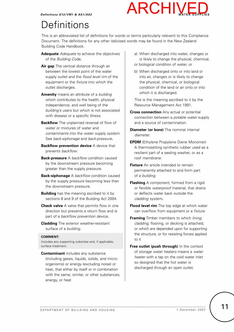
Adequate Adequate to achieve the objectives of the Building Code.
Air gap The vertical distance through air between the lowest point of the water supply outlet and the flood level rim of the equipment or the fixture into which the outlet discharges.
Amenity means an attribute of a building which contributes to the health, physical independence, and well being of the building’s users but which is not associated with disease or a specific illness.
Backflow The unplanned reversal of flow of water or mixtures of water and contaminants into the water supply system. See back-siphonage and back-pressure.
Backflow prevention device A device that prevents backflow.
Back-pressure A backflow condition caused by the downstream pressure becoming greater than the supply pressure.
Back-siphonage A backflow condition caused by the supply pressure becoming less than the downstream pressure.
Building has the meaning ascribed to it by sections 8 and 9 of the Building Act 2004.
Check valve A valve that permits flow in one direction but prevents a return flow and is part of a backflow prevention device.
Cladding The exterior weather-resistant surface of a building.
CoMMeNt:
Includes any supporting substrate and, if applicable, surface treatment.
Contaminant includes any substance (including gases, liquids, solids, and micro-organisms) or energy (excluding noise) or heat, that either by itself or in combination with the same, similar, or other substances, energy, or heat
a) When discharged into water, changes or is likely to change the physical, chemical, or biological condition of water, or
b) When discharged onto or into land or into air, changes or is likely to change the physical, chemical, or biological condition of the land or air onto or into which it is discharged.
This is the meaning ascribed to it by the Resource Management Act 1991.
Cross connection Any actual or potential connection between a potable water supply and a source of contamination.
Diameter (or bore) The nominal internal diameter.
epDM (Ethylene Propylene Diene Monomer) A thermosetting synthetic rubber used as a resilient part of a sealing washer, or as a roof membrane.
Fixture An article intended to remain permanently attached to and form part of a building.
Flashing A component, formed from a rigid or flexible waterproof material, that drains or deflects water back outside the cladding system.
Flood level rim The top edge at which water can overflow from equipment or a fixture.
Framing Timber members to which lining, cladding, flooring, or decking is attached; or which are depended upon for supporting the structure, or for resisting forces applied to it
Free outlet (push through) In the context of storage water heaters means a water heater with a tap on the cold water inlet so designed that the hot water is discharged through an open outlet.
DefinitionsThis is an abbreviated list of definitions for words or terms particularly relevent to this Compliance Document. The definitions for any other italicised words may be found in the New Zealand Building Code Handbook.
ARCHIVED

1 0 O c t o b e r 2 0 1 1 D E PA R T M E N T O F B U I L D I N G A N D H O U S I N G
w At e r S u p p l i e S Definit ionsG12/VM1&AS1/AS2
12
Household unit
a) means any building or group of buildings, or part of a building or group of buildings, that is:
i) used, or intended to be used, only or mainly for residential purposes; and
ii) occupied, or intended to be occupied, exclusively as the home or residence of not more than one household; but
b) does not include a hostel, boarding house or other specialised accommodation.
Masonry tiles Clay or concrete tile roof cladding.
Membrane A non-metallic material, usually synthetic, used as a fully supported roof cladding, deck surface or, in conjunction with other claddings, as gutters or flashings.
Network utility operator means a person who—
a) undertakes or proposes to undertake the distribution or transmission by pipeline of natural or manufactured gas, petroleum, biofuel, or geothermal energy; or
b) operates or proposes to operate a network for the purpose of—
i) telecommunication as defined in section 5 of the Telecommunications Act 2001; or
ii) radiocommunications as defined in section 2(1) of the Radiocommunications Act 1989; or
c) is an electricity operator or electricity distributor as defined in section 2 of the Electricity Act 1992 for the purpose of line function services as defined in that section; or
d) undertakes or proposes to undertake the distribution of water for supply (including irrigation); or
e) undertakes or proposes to undertake a drainage or sewerage system.
Non-return valve A valve that permits flow in one direction but prevents a return flow and is part of a hot or cold water system.
open vented storage water heater A waterheater incorporating a vent pipe which is permanently open to the atmosphere.
potable (and potable water) Water that is suitable for human consumption.
purlin A horizontal member laid to span across rafters or trusses, and to which the roof cladding is attached.
rafter A framing timber, normally parallel to the slope of the roof, providing support for sarking, purlins or roof cladding.
Sanitary appliance An appliance which is intended to be used for sanitation, but which is not a sanitary fixture. Included are machines for washing dishes and clothes.
Sanitary fixture Any fixture which is intended to be used for sanitation.
Sanitation The term used to describe the activities of washing and/or excretion carried out in a manner or condition such that the effect on health is minimised, with regard to dirt and infection.
Specific design Design and detailing of a proposed building or parts of a building, demonstrating compliance with the building code, that shall be provided to the building consent authority for assessment and approval as part of the building consent process.
Buildings, or parts of buildings, requiring specific design are beyond the scope of this Acceptable Solution.
Storage water heater A water tank with an integral water heater for the storage of hot water.
toxic environment An environment that contains contaminants that can contaminate the water supply in concentrations greater than those included in the New Zealand Drinking Water Standard 1995.
Valve vented storage water heater (Also known as an unvented storage waterheater.) A storage water heaterin which the required venting to the atmosphere is controlled by a valve.
Amend 8Oct 2011
ARCHIVED
w At e r S u p p l i e S
D E PA R T M E N T O F B U I L D I N G A N D H O U S I N G 1 0 O c t o b e r 2 0 1 1
AcceptableSolutionG12/AS1
21
b) In an accessible position for maintenance and testing to AS 2845.3 or NZ backflow testing standard.
3.6.2 Manufacture
Backflow prevention devices shall be manufactured as follows:
a) Reduced pressure zone devices to AS/NZS 2845.1 Section 11 (see Figure 2 (a)),
b) Double check valve devices to AS/NZS 2845.1 Section 10 (see Figure 2 (b)),
c) Pressure type vacuum breakers to AS/NZS 2845.1 Section 9, (see Figure 2 (c)), and
d) Atmospheric vacuum breakers to AS/NZS 2845.1 Section 4 for atmospheric vacuum breakers (see Figure 2 (d)), and Section 5 for hose tap vacuum breakers.
3.6.3 General installation requirements
Backflow prevention devices shall be:
a) Fitted with a line strainer upstream to prevent particles and corrosion products from the pipework rendering the device ineffective,
b) A by-pass may only be fitted where the by-pass contains another backflowpreventiondevice appropriate to the same hazard rating,
c) Protected from the effects of corrosive or toxic environments, and
d) Protected from damage.
CoMMeNt:
1. The device should be attached only after the pipework has been flushed.
2. Corrosive environments may cause the malfunction of the device. Polluted air from a toxic environment may enter the piping system through the air gap or open port vent thus negating the effective air gap separation.
3. The device should be protected from physical and frost damage and installed without the application of heat.
3.6.4 Specific installation requirements
Backflow prevention devices shall be installed as follows:
a) Reduced pressure zone devices. These devices shall:
i) have free ventilation to the atmosphere for the relief valve outlet at all times,
ii) be located in an area that is not subject to ponding,
iii) have the relief drain outlet located not less than 300 mm above the surrounding surface, and
iv) be installed horizontally with the relief valve discharge facing vertically down, unless different orientations are specifically recommended by the device manufacturer.
b) Double check valve devices. There are no additional requirements to those in Paragraph 3.6.3.
c) Pressure type vacuum breakers. These devices shall:
i) be located not less than 300 mm above the highest outlet, measured from the highest outlet to the lowest part of the valve body,
ii) be installed vertically with the air ports at the top, and
iii) have free ventilation to the air ports at all times.
d) Atmospheric vacuum breakers. These devices shall:
i) be located not less than 150 mm above the highest outlet, measured from the highest outlet to the lowest part of the valve body,
ii) have no valves located downstream of the vacuum breaker,
iii) under normal operation, not remain continuously pressurised for more than 12 hours,
iv) be installed vertically with the air ports at the top, and
v) Have free ventilation to the air ports at all times.
Amend 8Oct 2011
ARCHIVED

1 D e c e m b e r 2 0 0 7 D E PA R T M E N T O F B U I L D I N G A N D H O U S I N G
w At e r S u p p l i e S AcceptableSolutionG12/AS1
22
Figure 2:
Backflow prevention Devices Paragraph 3.6.2
ARCHIVED

w At e r S u p p l i e S
D E PA R T M E N T O F B U I L D I N G A N D H O U S I N G
AcceptableSolutionG12/AS1
23
3.7 testing
3.7.1 Backflow protection installations shall have the following provisions to enable routine testing of their operational effectiveness:
a) Resilient seated isolating valves shall be located immediately upstream and downstream of a reduced pressure zone device, double check valve assembly, or a pressure vacuum breaker,
b) A resilient seated isolating valve shall be located immediately upstream of an atmospheric vacuum breaker, and
CoMMeNt:
Full ported valves will provide the best flow characteristics.
c) Reduced pressure zone devices, double check valve assemblies and pressure vacuum breakers shall have sufficient test points to enable testing of each checkvalve and relief valve.
CoMMeNt:
Atmospheric vacuum breakers do not require test points.
3.7.2 Reduced pressure zone devices, double check valves and pressure vacuum breakers shall be tested and verified as meeting the test requirements of AS 2845.3 or NZ backflow testing standard.
3.7.3 Atmospheric vacuum breaker devices shall comply with the following test:
a) Operate the device by turning on the fixture or equipment and observe the operation. The poppet or float must close on increase in pressure, and
b) Operate the device by turning off the fixture or equipment and observe the operation. The poppet or float must open on decrease in pressure.
3.7.4 Backflow prevention devices shall be tested after installation or repair. Before testing the strainer shall be cleaned, the pipework flushed and the system commissioned.
CoMMeNt:
Testing is also required annually in accordance with Compliance Schedule CS 7, except for devices installed in single residential dwellings.
4.0 Non-potable Supply
4.1 protection of non-potable water supplies
4.1.1 Where non-potablewater supplies are used for personal hygiene they shall be protected from High and Medium hazards (see Paragraph 3.3). Where backflow protection is required it shall be in accordance with Paragraphs 3.1 to 3.7 of this Acceptable Solution. 4.2 outlet identification
4.2.1 NZBC F8 requires signs to be provided to all potential hazards. Outlets for non-potable water shall be identified non-potable, by displaying the safety sign shown in Figure 3.
4.3 pipeline identification
4.3.1 Where a non-potable water supply is reticulated around the building, the potable and non-potable pipelines shall be identified in accordance with NZS 5807: Part 2.
1 0 O c t o b e r 2 0 1 1
Figure 3:
Non-potable water Sign Paragraph 4.2.1 Amend 5
Feb 2004
Amend 5 Feb 2004
Amend 5 Feb 2004
Amend 5 Feb 2004
Amend 8Oct 2011
ARCHIVED

1 D e c e m b e r 2 0 0 7 D E PA R T M E N T O F B U I L D I N G A N D H O U S I N G
w At e r S u p p l i e S AcceptableSolutionG12/AS1
24
5.0 water Supply
5.1 water tanks
5.1.1 To ensure the health and safety of people in the event of the water main supply being interrupted, buildings having the classification of Community Care (e.g. hospitals, old people’s homes, prisons) shall be provided with cold water storage of no less than 50 litres per person.
CoMMeNt:
1. Cold water storage is required only to maintain adequate personal hygiene within buildings where the principal users are legally or physically confined.
2. Refer to the NZBC A1 for classification of buildings.
3. Network utility operators cannot guarantee a continuous supply of water. Building owners may therefore wish to provide water storage to buildings having a classification other than Community Care, to enable continuation of a business, service, industrial process or other reason.
4. The “litres per person” is based on a daily use of 20 litres WC, 25 litres washing, 5 litres drinking.
5.2 water tank installation
5.2.1 location
Water tanks in roof spaces shall be located and supported as detailed in Figure 4.
5.2.2 overflow pipes
Water tanks shall have an overflow pipe to discharge any overflow to a visible place within the same property that does not create a nuisance or damage to building elements. The overflow pipe shall be sized so that the discharge capacity is no less than the maximum inlet flow. The outlet of the overflow pipe shall not permit the entry of birds or vermin. Overflow from a WC cistern may discharge internally into a WC pan.
5.2.3 Safe trays
Performance E3.3.2 requires water to be prevented from penetrating another household unit within the same building. An acceptable method of preventing water damage is to locate a safe tray below the water tank (see Figure 4). The safe tray shall incorporate an overflow pipe with a minimum diameter of 40 mm. Where the tank overflow discharges
into the safe tray the diameter of the drain shall be greater than the overflow pipe from the tank and comply with Paragraph 5.2.2.
5.2.4 Covers
Covers shall be provided to:
a) Potable water tanks to prevent contamination and the entry of vermin, and
b) All tanks located in roof spaces to prevent condensation damaging building elements.
5.2.5 Access
Covers to water tanks shall be removable or shall contain a covered opening to allow access for inspection and maintenance. A minimum height clearance of 350 mm above the opening is necessary for easy access.
5.2.6 Supporting structure
The supporting structure for water tanks shall be protected from damage due to condensation where durability of the supports could be compromised by moisture. A material such as H3 treated timber shall be installed under the water tank.
5.2.7 Structural support
NZBC B1 requires water tanks to be adequately supported including seismic restraint. The method illustrated in Figure 4 is acceptable for water tanks up to 150 litre capacity and the maximum height to breadth ratio of 1:1.
5.3 water pipe size
5.3.1 pipe sizing
Pipes shall be sized:
a) To achieve the flow rates given in Table 3, or
b) Using the sizes given in Table 4.
CoMMeNt:
Manufacturers’ literature must be referenced for pressure and flow information on tempering valves and tapware. Outlets (e.g. shower mixers and showerheads) must be appropriate for the available flow and pressure. Note the limitations on lengths and pipe sizes given in Table 3.
ARCHIVED

w At e r S u p p l i e S
D E PA R T M E N T O F B U I L D I N G A N D H O U S I N G 1 0 O c t o b e r 2 0 1 1
AcceptableSolutionG12/AS1
41
a) Electricity is provided within a building,
b) The water supply pipe is metallic,
c) Building users are able to make contact with exposed parts of metal water supply pipe, or any metallic sanitary fixturesconnected to it, and
d) The metal pipe is in contact with the ground, and forms a continuous metallic link from the ground to those parts of the pipe exposed to building users.
CoMMeNt:
No equipotential bonding is required if the water supply piping is plastic.
9.2 installation of equipotential bonding conductors
9.2.1 water supply pipe
a) Metallic water supply pipe shall be bonded to the earth electrode with an equipotential bonding conductor, as shown in Figure 19. The connection to the water pipe shall be as close as practicable to the point where the pipe leaves the ground, and
b) Metallic hot and cold water supply pipes shall be bonded together.
9.2.2 Metallic sanitary fixtures
a) Metallic sanitary fixtures shall be bonded to the metallic water supply pipe with an equipotential bonding conductor, as shown in Figure 20.
CoMMeNt:
Metallic sanitary fixtures are only required to be bonded to metallic water supply pipes where it is possible for a person to simultaneously touch the pipe (via a tap) and the fixture.
b) The bonding conductor shall be connected directly to the sanitary fixture. The bonding conductor may connect to the waste pipe where a metallic waste pipe is connected to the sanitary fixture and a continuous metallic link is formed between the waste pipe and the fixture.
9.3 earth bonding conductors
9.3.1 Earth bonding conductors shall be:
a) Made of copper and have a cross-sectional area no less than 4.0 mm2,
b) Sheathed with insulating material coloured green, and
c) Fixed at intervals of no greater than 300 mm with aluminium cable fixings.
9.3.2 Earth bonding conductors shall comply with AS/NZS 5000.1 or AS/NZS 5000.2 as appropriate.
Figure 20:
equipotential Bonding of Metallic Sanitary Fixtures Paragraph 9.2.2 a)
Amend 7Sep 2010
Amend 8Oct 2011
ARCHIVED

42
ARCHIVED
S o l A r w At e r H e At e r S
D E PA R T M E N T O F B U I L D I N G A N D H O U S I N G 1 0 O c t o b e r 2 0 1 1
AcceptableSolutionG12/AS2
Acceptable Solution G12/AS2 Solar Water Heaters
43
1.0 Scope
1.0.1 This Acceptable Solution applies to solar water heaters installed in or on buildings.
1.0.2 To comply with this Acceptable Solution solar water heaters must also comply with the appropriate requirements of G12/AS1. This Acceptable Solution meets the requirements of NZBC Clauses B1, B2, E2, G12 and H1.
1.0.3 Text boxes headed ‘CoMMeNt’ occurring throughout this document are for guidance purposes only.
1.1 Structural support limitations
1.1.1 Where a building has not been specifically designed to support a solar water heater, this Acceptable Solution can be used for the support and fixing of a solar collector on buildings that meet the structural requirements specified in any one of the following:
• NZS 3604: 1990
• NZS 3604: 1999
• NZS 3604: 2011
• NZS 4203
• AS/NZS 1170: Parts 0, 1, 2, 3 and NZS 1170: Part 5.
But only when all of the following requirements are met:
a) the weight of solar collector, including frames, fittings, and heat transfer fluid, has a combined weight of no more than 22 kg per square metre (based on the gross area of the solar collector), and
b) the hot water storage tank is not installed on or above the roof, and
c) where the hot water storage tank is located within a roof it has a maximum size of:
i) 200 litres when installed in accordance with NZS 3604: 1999 Section 14, or
ii) 450 litres when installed in accordance with AS/NZS 3500 Part 4: 2003 Section 5, and
d) the roof has a pitch no steeper than 45°, and
e) the building is in a wind zone where wind speeds do not exceed 50 m/s (VH windzone defined in NZS 3604: 1999), and
f) the solar collector has an area no greater than 4 m2, and
g) the design ground snow loading for the building is less than:
(i) 0.5 kPa as determined by NZS 4203, or NZS 3604: 1990 or NZS 3604: 1999 Section 15, or
(ii) 1.0 kPa as determined by AS/NZS 1170 or NZS 3604: 2011, Section 15, and
h) either:
i) the solar collectors are installed parallel to the roof cladding, or
ii) where solar collectors are installed at a different pitch to the pitch of the roof:
– the pitch of the solar collector is not greater than 45° to the horizontal, and
– the building is in a wind zone where wind speeds do not exceed 44 m/s (H wind zone defined in NZS 3604: 1999), and
– the solar collector faces in the same compass direction as the section of roof the solar collector is installed on.
CoMMeNt:
1. The limitations described in Paragragh 1.1.1 are necessary, because roofs are likely to have limited capacity to support additional loads.
1.1.2 When any of the requirements described in Paragraph 1.1.1 are not met, specific engineering design is required.
CoMMeNt:
Specific engineering design will require a structure assessment to be completed. This may result in either an assessment that the roof structure is sufficient to support the additional load or details of how to strengthen the roof structure to support the additional load.
Amend 8Oct 2011
Amend 8Oct 2011
ARCHIVED
1 D e c e m b e r 2 0 0 7 D E PA R T M E N T O F B U I L D I N G A N D H O U S I N G
S o l A r w At e r H e At e r S AcceptableSolutionG12/AS2
44
1.2 exclusions
1.2.1 If the solar water heater includes connection to an application such as underfloor heating, a swimming pool or any similar application, this Acceptable Solution applies only to the solar water heater and its components and not to the application.
2.0 Materials
2.1 Material selection
2.1.1 All material used to install the solarwater heater must:
a) meet the durability requirements of NZBC Clause B2, and
b) be suitable for their use, location and environment as shown in Table 1, and
c) be compatible with adjoining materials as shown in Table 2, and
d) be compatible with materials subject to run-off as shown in Table 3 (except as described in Paragraph 2.1.2).
2.1.2 Table 3 states that “butyl/EPDM” to “steel, galvanized unpainted” is “not permitted”; however, water flow from small areas of EPDM will not significantly affect the durability of the roofing. Therefore it is acceptable to use unpainted EPDM boots with unpainted galvanised steel roofing if:
a) the boots are small (for 60 mm pipe diameter or smaller), and
b) there are no more than 10 boots used for the solar water heater installation, and
c) the boots contain no greater than 15% carbon black.
2.1.3 If the requirements described in Paragragh 2.1.2 are not met then either the EPDM boots or the galvanised roofing must be painted with a suitable protective coating.
2.1.4 Table 2 shows that galvanized fixings must be used rather than stainless steel when in contact with galvanized cladding and zinc/aluminium coated cladding. (This includes mounting brackets and straps.)
.
ARCHIVED