Embed Size (px)
Citation preview

U. S. Department of Agriculture *Forest Service *Forest Products Laboratory *Madison, Wis.
COMPOSITE BEAMS--
ADHESIVE OR FASTENER RIGIDITY
U.S.D.A. FOREST SERVICERESEARCH PAPER
FPL 1521971

ABSTRACT
An analysis capable of predicting the deflections and stresses forcomposite beams with finite fastener rigidity is reported. Experimentalresearch involving evaluation of several composites indicates applica-bility and limitations of the analysis.
Results of this study can be used for more efficient designs of struc-tural components (thus resulting in a reduction in the amount of woodneeded) in built-up panels to allow wider choice of materials for possiblefabrication at the building site, or for other similar applications.

COMPOSITE BEAMS--EFFECT OFADHESIVE OR FASTENER RIGIDITY
EDWARD W.
by
KUENZI, Engineerand
THOMAS LEE WILKINSON, Engineer
Forest Products Laboratory Forest ServiceU.S. Department of Agriculture
INTRODUCTION
Maximum utilization of materials in structural components can only berealized by rational design of composites wherein materials or portionsof the cross sections of composites are held together rigidly. Fasten-ing methods which are less than infinitely rigid will require morematerials to increase dimensions to provide needed rigidity.
Built-up structural pieces with complete interaction, such as can be madeby gluing the pieces together with a rigid adhesive, or with no inter-action have been analyzed to determine their deflection and strength.However, pieces fastened with nails or mastics where there is only partialinteraction have not been analyzed. If an analysis could be made, theadditional stiffness provided by partial interaction could be taken intoaccount in the design of structures.
Maintained at Madison, Wis., in cooperation with the University ofWisconsin.
PAST WORK
A study by New-mark 2- dealt with incomplete interaction of composite steeland concrete T-beams consisting of two interacting elements. A theoreti-cal analysis was developed which incorporated the load-slip characteris-tics of steel channel shear connectors. The degree of interaction forthese beams was such that the theoretical values for complete and incompleteinteraction differed only slightly. However, the test results generallyagreed with the theory.
OBJECTIVE
This study was to determine a theoretical means of determining the deflec-tions and stresses for composite wood beams assembled with adhesives orfasteners having finite rigidity, and to verify the theory experimentally.This would provide a means for rational design of various composites ifthe properties of the components, including fastener rigidity, were known.
THEORETICAL ANALYSIS
The mathematical analysis of sandwich constructions having stiff facings
bonded to a core of low shear rigidity as derived in 1505A 3- is utilizedto define parameters and arrive at theoretical expressions for deflectionsand stresses of composite beams assembled with adhesives or fasteningshaving finite rigidity.
For a beam of composite construction, simply supported at the reactionsand loaded at two points a distance kL from the reactions as shown infigure 1,
-2 Newmark, N. M., Siess, C. P., and Viest, I. M. "Test and analyses ofcomposite beams with incomplete interaction.” Society for ExperimentalStress Analysis, Vol. 9, No. 1, 1951.
-3 Norris, Charles B., Ericksen, Wilhelm S., and Kommers, Wm. J. “Flexuralrigidity of a rectangular strip of sandwich construction--comparisonbetween mathematical analysis and results of tests.” Forest Prod.Lab. Rep. 1505A. May 1952.
FPL 152 -2-

F igure I. - - B e a m l o a d i n g . M I38 607
the midspan deflection is given by the following expression derived from3
the mathematical analysis:—
(1)
where ∆ is midspan deflectionP is applied loadL is span lengthk defines load position as shown in figure 1
(EI) is stiffness of composite beam as if parts were glued togetherwith a rigid adhesive
is stiffness of all beam parts as if unglued
(2)
h is distance between centroids of principal moment-carrying membersS is shear load per unit span length to cause unit slip between
principal moment-carrying members. 4-
-4Values of S can be determined from the slope of a shear-slip curve forthe type of fastening employed (adhesive or nails). The shear-slipcurve can be obtained from a small shear specimen joined with the sameadhesives or fastenings as the composite beam. The width of the speci-men should be equal to that of a composite beam shear joint width foradhesives or should contain the same number of fasteners such as nailsper width of beam shear joint as in the composite beam. An effectivejoint shear rigidity, γ, with units such as pounds per inch of lengthper inch of slip, can be obtained by dividing the slope of the shear-slip curve by the length of the shear specimen for adhesives or by the
nail spacing in the composite beam. S is given by S = ~ Y, where n is
the number of shear planes across the width of the composite beam andm is the number of shear planes through the depth of the beam. Use ofthis formula for S with beams of more than two layers may only giverough approximations because it assumes each slip-layer has the sameamount of slip.
- 3 -

FPL 152 -4-

Formula (1) for several familiar loadings becomes:
For k = 1/2 (midspan loading)
where
For k = 1/4
where
(3)
(4)
For a beam, simply supported at the reactions, and loaded with a uniformly
distributed load, the midspan deflection is given by: 5-
where
(5)
where W is the total load uniformly distributed.
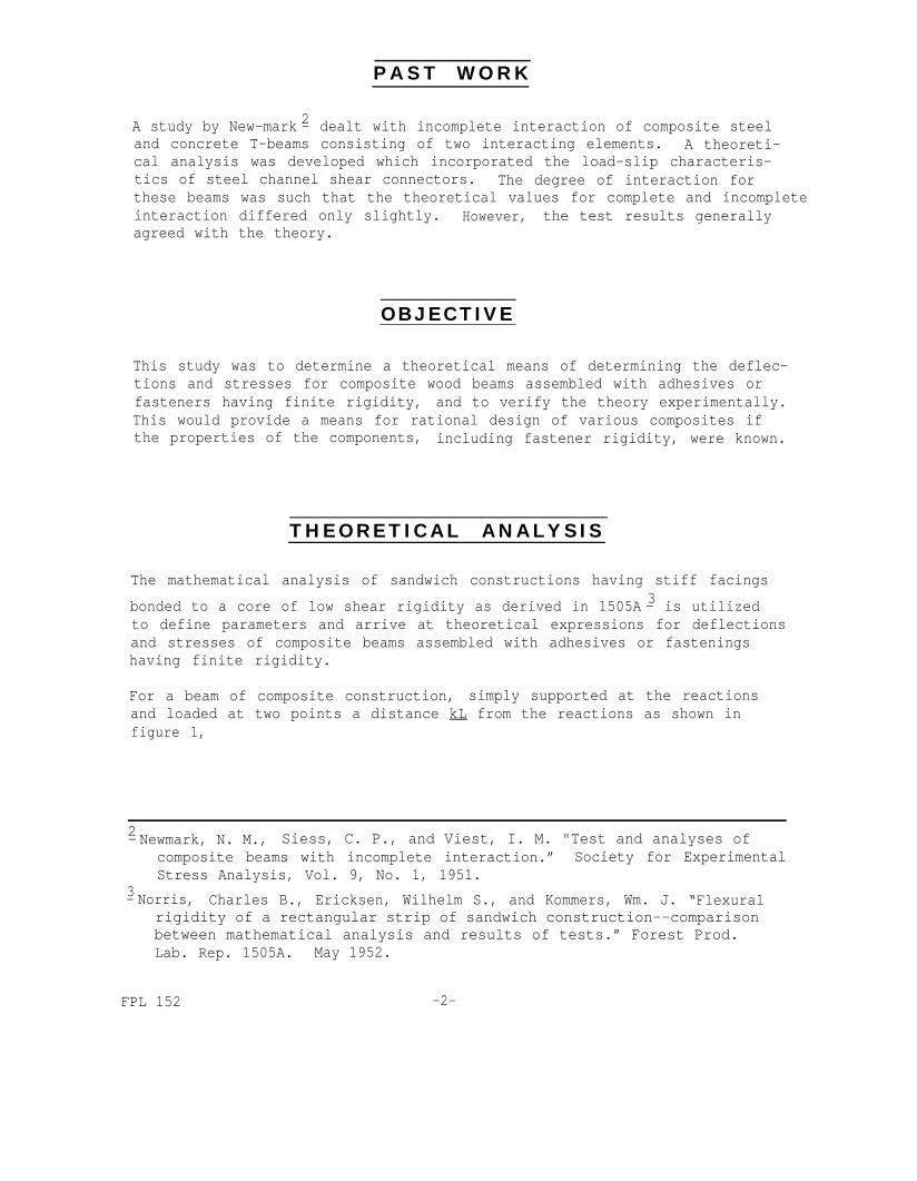
Graphs of J∆ , N∆ , and K∆are shown as families of straight lines having
()
CXLslopes dependent upon the parameter T
in figures 2, 3, and 4.
The shear stress is maximum at the reactions and is assumed to be constantthroughout the thickness of an adhesive joint and inner members in acomposite beam. For beams under concentrated loads, figure 1, the shearstress at the reactions is given by the formula:
This case was not covered in 1505A. A derivation based on that referenceis given in appendix A.
-5-

where b is the width of the joined surface.
For k = 1/2 (midspan loading)
where
For k = 1/4
where
(6)
(7)
(8)
For beams under uniformly distributed load, the shear stress at the reac-tion is
where
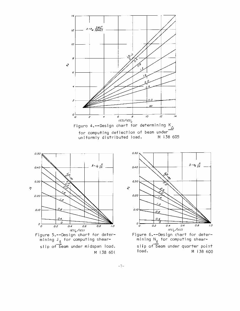
Graphs of Jδ , N δ, and K δ are shown in figures 5, 6, and 7.
(9)
FPL 152
The shear slip between principal moment-carrying members of the compositebeam is given by the formula:
(10)
-6-
-7-
Maximum compression and tension stresses occur at the surfaces of the beamand at the load points for beams with two concentrated loads, each adistance kL from each reaction, and at midspan for beams with load uni-formly distributed. These maximum stresses are given by the followingformulas:
For beam under concentrated loads--
(11)
(12)
FPL 152 -8-
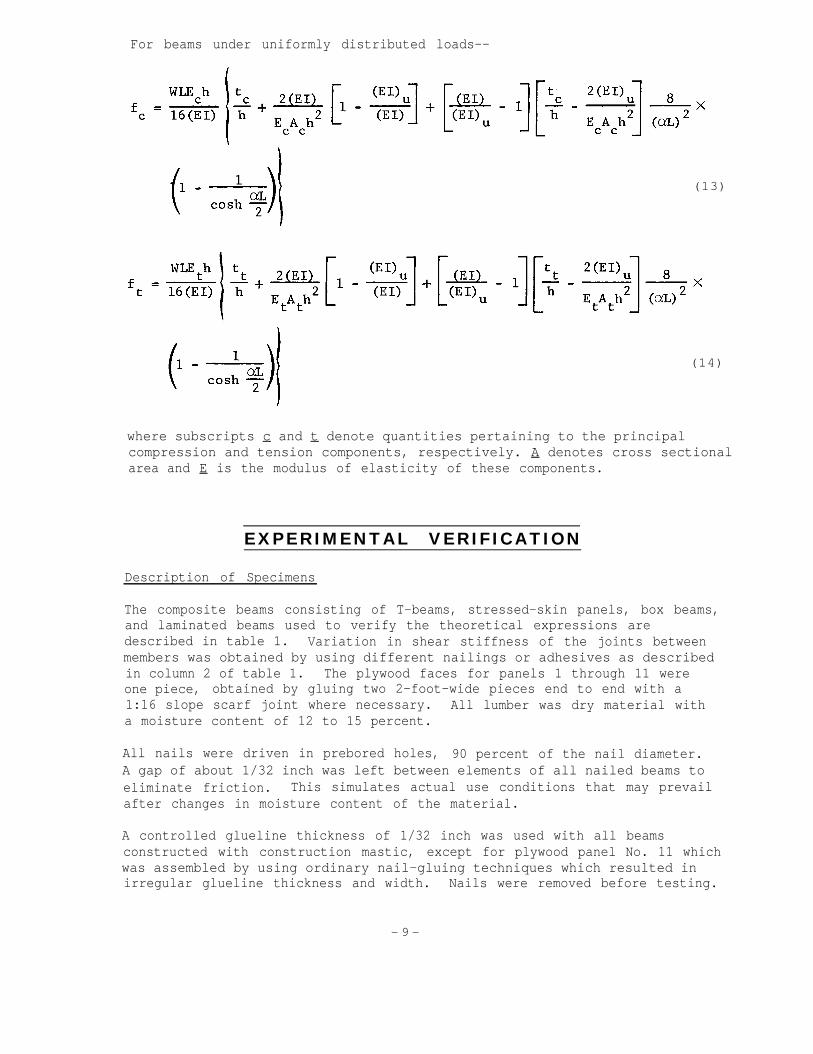
For beams under uniformly distributed loads--
(13)
(14)
where subscripts c and t denote quantities pertaining to the principalcompression and tension components, respectively. A denotes cross sectionalarea and E is the modulus of elasticity of these components.
EXPERIMENTAL VERIFICATION
Description of Specimens
The composite beams consisting of T-beams, stressed-skin panels, box beams,and laminated beams used to verify the theoretical expressions aredescribed in table 1. Variation in shear stiffness of the joints betweenmembers was obtained by using different nailings or adhesives as describedin column 2 of table 1. The plywood faces for panels 1 through 11 wereone piece, obtained by gluing two 2-foot-wide pieces end to end with a1:16 slope scarf joint where necessary. All lumber was dry material witha moisture content of 12 to 15 percent.
All nails were driven in prebored holes, 90 percent of the nail diameter.A gap of about 1/32 inch was left between elements of all nailed beams toeliminate friction. This simulates actual use conditions that may prevailafter changes in moisture content of the material.
A controlled glueline thickness of 1/32 inch was used with all beamsconstructed with construction mastic, except for plywood panel No. 11 whichwas assembled by using ordinary nail-gluing techniques which resulted inirregular glueline thickness and width. Nails were removed before testing.
- 9 -

The length of all beams was slightly longer than the indicated spans intable 1.
Test Procedure
The beams were loaded with line loads across their width at midspan orquarter span as indicated in table 1. Deflections at midspan were measuredwith dial gages, reading to the nearest 0.001 inch, mounted on yokes whichwere suspended from the beams at the reactions. Shear slip between theprincipal moment-carrying members was measured with a dial gage, readingto the nearest 0.0001 inch, mounted on the beam at the reaction.
Data were collected in the form of load-deflection and load-shear slipcurves. Before obtaining these curves for nailed beams, the beams weresubjected to two to three cycles of preloading. This has been found toresult in linear load-shear slip curves. The level of load was limited tothat which would not cause a slip greater than 0.012 inch at the higheststressed nail (directly over the reaction).
Face strain, 6 inches from midspan, was measured with a Tuckerman straingage on plywood panel No. 8 and with an electrical-resistance strain gageon the five-layer laminated beam, No. 22.
Data for computing S values for nailed joints were based on previoustheoretical considerations of the lateral resistance of nailed joints. 6-The values of the load-slip curve slopes for nailed joints were computed
for Douglas-fir having an average specific gravity 7- of 0.45 and for white
pine having an average specific gravity 8- of 0.38.
Shear load-slip data for computation of S values were obtained for jointswith construction mastic adhesives by testing small shear specimens.These specimens were 5 to 6 inches in length, about 1-1/2 inches wide, andhad an adhesive layer controlled to a thickness of 1/32 inch by using woodveneer shims 1/8 inch wide at the specimen edges. The specimen was made2 inches wide and the shims were sawn off when the specimen was cut tol-1/2-inch width after proper curing of the adhesive. The shear testapparatus with a dial gage mounted on the specimen for measuring shearslip is shown in figure 8. A shear stress-slip curve obtained for aconstruction mastic adhesive is shown in figure 9. The curve does nothave a linear portion during initial loading; however, on second and sub-sequent loadings a short linear portion that appeared at low slip wasused to compute an S value. In using test data to compute S , it should berecalled that the rigidity of the adhesive joint will vary inversely asthe adhesive thickness.
-6Wilkinson, Thomas Lee. : Theoretical lateral resistance of nailed joints." (Submitted to ASCE for publication.)
-7U.S. Forest Service. Western Wood Density Survey, Report No. 1. U.S.Forest Service Res. Pap. FPL 27. July 1965.
-8 Forest Products Laboratory. Wood Handbook. U.S.D.A. Agr. Handb. 72,1955.
FPL 152 -10-

Table 1.--Construction and properties of composite beams
Slip is the movement at the reaction between the top amd bottom pieces.

FPL 152
Figure 8. --Shear test apparatus for obtainingl o a d - s l i p d a t a f o r c o n s t r u c t i o n m a s t i cadhes ive. M 138 260
-12-

The rectangular beams No. 12-19 and 22, 23, and 24 were square in crosssection and their stiffness as if glued with a rigid adhesive, (EI), wasdetermined by loading the beams with the laminations vertical. For theother constructions, the stiffness of the individual elements was measuredbefore assembling the beams; from the dimensions of the components andtheir elastic moduli, the stiffness as if rigidly glued, (EI), wascomputed with basic mechanics theory.
Results
Composite beam properties and experimental and theoretical results aregiven in table 1. Details of the composite beam constructions and proper-ties are given in columns 1, 2, and 3,
Ratios of (EI)/(EI)u for the various constructions as given in column 4
ranged from 2.56 to 27.65, thus covering a wide variety of composites withwhich to check the effectiveness of joint rigidities. Column 7 givesvalues of JD or ND which range from 1.62 to 8.72. These computed values
of J~ or NTare the ratios of beam deflections with joint slip to deflec-—.
tions of beams with rigid joints. Thus the computed deflections of thecomposite beams were from 1.62 to 8.72 times the deflections of the beamsif rigidly glued or somewhat less than for beams with no glue as indicatedby the larger values of the ratios of (EI)/(EI)u in column 4.
-13-

Load-deflection ratios tabulated in column 8 show there was good agreementbetween theoretical and experimental deflection for the beams evaluated.A graphical representation of theoretical and experimental load-deflectionratios in figure 10 shows good agreement between experimental and theo-retical values. This is probably the most important property to be ableto predict for composite beams, as it will quite often govern their designin many structures. Fair agreement was found between theoretical andexperimental load-shear slip ratios tabulated in column 9 and shown in thegraph of figure 11. The notable exceptions were the four- and five-layerlaminated beams. This lack of agreement is probably due to the assumptionof constant shear stress throughout the thickness of all inner members.
Comparison of theoretical and experimental face strain, table 1, showsgood agreement for the plywood panel and poor agreement for the five-layerlaminated beam. This poor agreement is again probably due to the assump-tion of constant shear stress throughout the inner members.
The general agreement between experimental and theoretical values enablesuse of the theory to predict effects of time, temperature, moisture, etc.,on composites by evaluating basic properties E and S as affected by thesesame variables of time, temperature, moisture, etc. Thus evaluation ofE and S can be determined on small specimens rather thancomposites to assess the effects of these variables.
evaluating large
FPL 152 -14-

CONCLUSIONS
The good agreement of experiment and theory for deflection and shear-slipof composite beams of two or three continuous layers demonstrates thatthe theory presented can be used for rational design of members with finitefastener rigidity.
-15-

APPENDIX A
Derivation of Formulas For Beam UnderUniformly Distributed Load*
For a simple supported beam under a total load W that is uniformly distrib-uted along a beam of length L , the bending moment at a point located adistance x from a reaction is given by:
and the shear load by:
(Al)
(A2)
The analysis given in the appendix of FPL 1505A derives the differentialequation for the shear stress, τ , to be:
with terms defined in the
Substitution of (A2) into
Theoretical Analysis section of this report.
(A3) results in:
which has a solution:
(A3)
(A4)
(A5)
*Derived from FPL Report 1505A by Norris, Ericksen, and Kommers (foot-
note 2).
FPL 152 -16-

and substitution of (A6) and (A7) into (A5) results in:
(A6)
(A7)
(A8)
The analysis in the appendix of FPL 1505A leads to the differential equa-tion for the deflection, ∆ :
which after integrationin:
(A9)
and evaluation of integration constants, results
(A1O)
and evaluation of formula (A1O) at midspan leads eventually to formula (5).
-17-

APPENDIX B
Sample Calculation
Determine the deflection and shear slip at the reaction for a stressed-skin panel 48 inches wide having 3/4-inch Douglas-fir plywood faces onthree Douglas-fir stringers each 1-1/2 inches wide and 3-1/2 inches deep.The beam is subjected to a concentrated load of P pounds at the middleof its 92-1/2-inch span. The plywood is nailed to the stringers witheightpenny common nails, spaced 8 inches on center. The following proper-ties are known:
(1) Slope of the load-slip curve for an eightpenny nail--l6,8OO lb. per in.
(2) Modulus of elasticity of Douglas-fir--El = 1,800,000 lb. per in.2
(3) Bending stiffness of 3/4-inch plywood--(EI)p = 0.023 El lb.-in.2
per in. of width, and
(4) Extensional stiffness of 3/4-inch plywood--(EA)p = 0.42 El lb.-in.2
per in. of width.
Solution:
(B1)
Stringer bending stiffness
lb.-in.2 for
Plywood bending
lb.-in.2
for
each stringer (B2)
stiffness
each skin. (B3)
(B4)
(B5)
FPL 152 -18-

From formula (2),
From figure 2, J∆ = 4.85 and from figure 5, J δ = 0.33.
The midspan deflection is
(B6)
(B7)
(B8)
(B9)
(B1O)
(Bll)
which is 4.85 times the deflection of the panel if it were glued with arigid adhesive.
The shear-slip between the two plywood faces at the reaction is:
(B12)
For a proportional limit slip of 0.012 in. per nail, the maximum shearslip between the plywood faces would be 0.024 inches, because of twoshear planes, and the load would be
0.0000247P = 0.024
P = 970 lb.
-19-

and at this load the deflection would be
∆ = 0.000222(970) = 0.216 in.
with resulting span-deflection ratio of 428. Thus, the panel is amplystiff provided the load does not exceed 970 pounds.
FPL 152 -20-
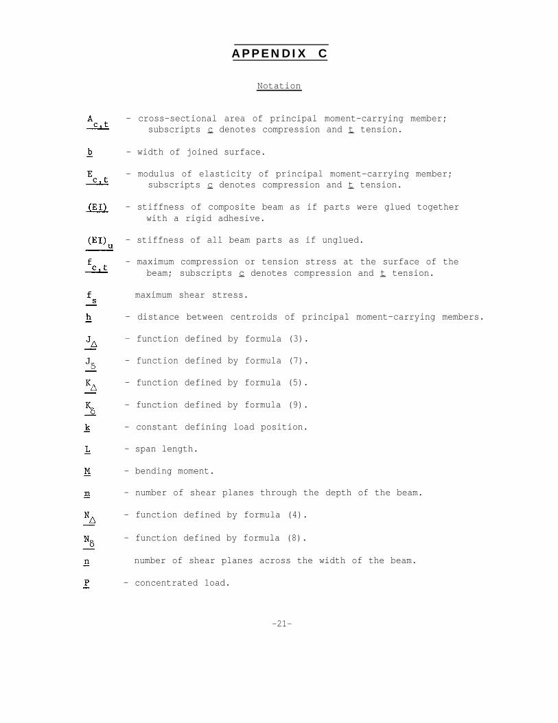
APPENDIX C
Notation
- cross-sectional area of principal moment-carrying member;subscripts c denotes compression and t tension.
- width of joined surface.
- modulus of elasticity of principal moment-carrying member;subscripts c denotes compression and t tension.
- stiffness of composite beam as if parts were glued togetherwith a rigid adhesive.
- stiffness of all beam parts as if unglued.
- maximum compression or tension stress at the surface of thebeam; subscripts c denotes compression and t tension.
maximum shear stress.
- distance between centroids of principal moment-carrying members.
- function defined by formula (3).
- function defined by formula (7).
- function defined by formula (5).
- function defined by formula (9).
- constant defining load position.
- span length.
- bending moment.
- number of shear planes through the depth of the beam.
- function defined by formula (4).
- function defined by formula (8).
number of shear planes across the width of the beam.
- concentrated load.
-21-
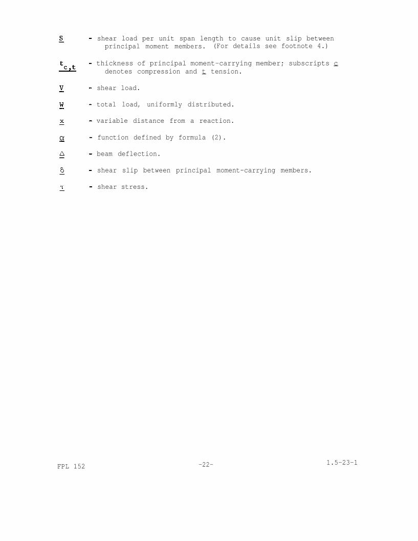
shear load per unit span length to cause unit slip betweenprincipal moment members. (For details see footnote 4.)
thickness of principal moment-carrying member; subscripts cdenotes compression and t tension.
shear load.
total load, uniformly distributed.
variable distance from a reaction.
function defined by formula (2).
beam deflection.
shear slip between principal moment-carrying members.
shear stress.
FPL 152 -22- 1.5-23-1

ABOUT THE FOREST SERVICE. . . .
As our Nation grows, people expect and need more from their
forests-- more wood; more water, fish and wildlife; more recreation
and natural beauty; more special forest products and forage. The ForestService of the U.S. Department of Agriculture helps to fulfill these
expectations and needs through three major activities:
* Conducting forest and range research at over
75 locations ranging from Puerto Rico to Alaska
to Hawaii.
* Participating with all State forestry agencies in
cooperative programs to protect, improve, and
wisely use our Country’s 395 million acres ofState, local, and private forest lands.
* Managing and protecting the 187-million acre
National Forest System
The Forest Service does this by encouraging use of the new knowledgethat research scientists develop; by setting an example in managing,
under sustained yield, the National Forests and Grasslands for multiple
use purposes; and by cooperating with all States and with private
citizens in their efforts to achieve better management, protection, anduse of forest resources.
Traditionally, Forest Service people have been active members ofthe communities and towns in which they live and work They strive to
secure for all, continuous benefits from the Country’s forest resources.
For more than 60 years, the Forest Service has been serving the
Nation as a leading natural resource conservation agency.


![RIGIDITY OF GROUP ACTIONS [12pt] I. Introduction to Super-Rigidity](https://img.pdfslide.net/doc/110x75/613d4e5f736caf36b75bc34e/rigidity-of-group-actions-12pt-i-introduction-to-super-rigidity.jpg)