Embed Size (px)
DESCRIPTION
Composite Joining and Joints
Citation preview
7/17/2019 Composite Joining and Joints
http://slidepdf.com/reader/full/composite-joining-and-joints 1/12
19-1
19 COMPOSITE JOINING AND JOINTS
7/17/2019 Composite Joining and Joints
http://slidepdf.com/reader/full/composite-joining-and-joints 2/12
19-2
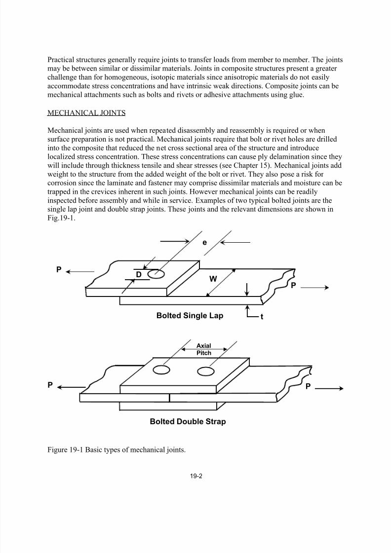
Practical structures generally require joints to transfer loads from member to member. The jointsmay be between similar or dissimilar materials. Joints in composite structures present a greater
challenge than for homogeneous, isotopic materials since anisotropic materials do not easily
accommodate stress concentrations and have intrinsic weak directions. Composite joints can be
mechanical attachments such as bolts and rivets or adhesive attachments using glue.
MECHANICAL JOINTS
Mechanical joints are used when repeated disassembly and reassembly is required or when
surface preparation is not practical. Mechanical joints require that bolt or rivet holes are drilled
into the composite that reduced the net cross sectional area of the structure and introducelocalized stress concentration. These stress concentrations can cause ply delamination since they
will include through thickness tensile and shear stresses (see Chapter 15). Mechanical joints add
weight to the structure from the added weight of the bolt or rivet. They also pose a risk forcorrosion since the laminate and fastener may comprise dissimilar materials and moisture can be
trapped in the crevices inherent in such joints. However mechanical joints can be readilyinspected before assembly and while in service. Examples of two typical bolted joints are thesingle lap joint and double strap joints. These joints and the relevant dimensions are shown in
Fig.19-1.
Bolted Single Lap
Bolted Double Strap
W
e
DP
P
PP
AxialPitch
t
Figure 19-1 Basic types of mechanical joints.
7/17/2019 Composite Joining and Joints
http://slidepdf.com/reader/full/composite-joining-and-joints 3/12
19-3
The single lap joint is the simplest and most weight efficient but the load results in a moment due
to off-set load. The double lap joint eliminate the moment but adds additional weight from thestraps and additional bolt.
Failure modes in mechanical joints
The composite designer must consider four relevant stresses in mechanical joints. The bearing
stress, bσ is the load, P divided by the projected transverse cross sectional area of the
hole b P Dt σ = . The shearout stress is determined by the longitudinal shear surfaces, and is
given as 2SO P et σ = . The net section stress is ( ) N P t W Dσ = − . The transverse splitting stress
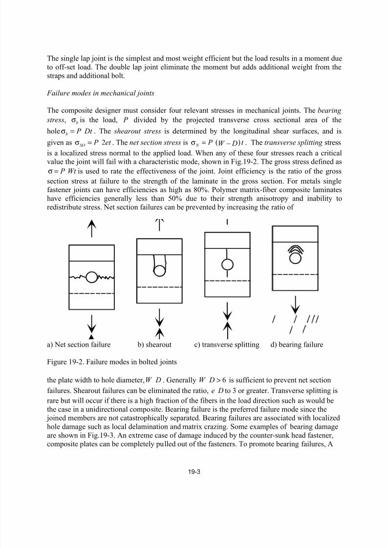
is a localized stress normal to the applied load. When any of these four stresses reach a criticalvalue the joint will fail with a characteristic mode, shown in Fig.19-2. The gross stress defined as
P Wt σ = is used to rate the effectiveness of the joint. Joint efficiency is the ratio of the gross
section stress at failure to the strength of the laminate in the gross section. For metals single
fastener joints can have efficiencies as high as 80%. Polymer matrix-fiber composite laminateshave efficiencies generally less than 50% due to their strength anisotropy and inability to
redistribute stress. Net section failures can be prevented by increasing the ratio of
a) Net section failure b) shearout c) transverse splitting d) bearing failure
Figure 19-2. Failure modes in bolted joints
the plate width to hole diameter,W D . Generally 6W D
> is sufficient to prevent net section
failures. Shearout failures can be eliminated the ratio, e D to 3 or greater. Transverse splitting is
rare but will occur if there is a high fraction of the fibers in the load direction such as would be
the case in a unidirectional composite. Bearing failure is the preferred failure mode since the joined members are not catastrophically separated. Bearing failures are associated with localized
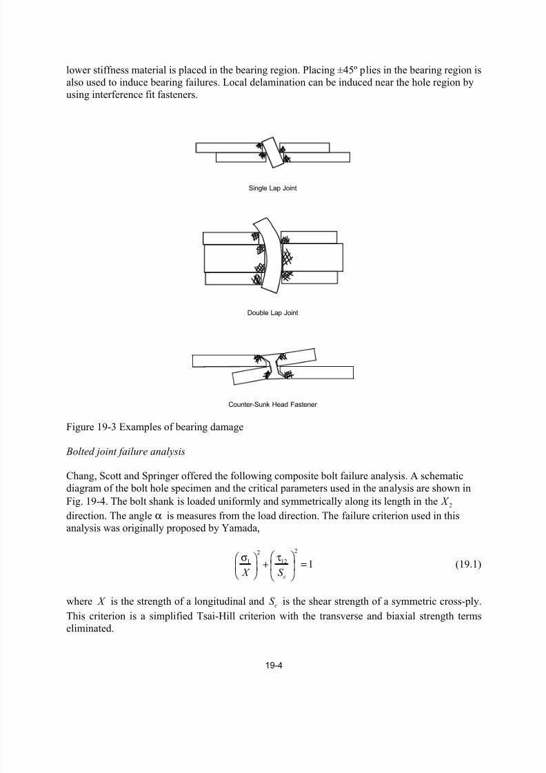
hole damage such as local delamination and matrix crazing. Some examples of bearing damage
are shown in Fig.19-3. An extreme case of damage induced by the counter-sunk head fastener,composite plates can be completely pulled out of the fasteners. To promote bearing failures, A
7/17/2019 Composite Joining and Joints
http://slidepdf.com/reader/full/composite-joining-and-joints 4/12
19-4
lower stiffness material is placed in the bearing region. Placing ±45º plies in the bearing region is
also used to induce bearing failures. Local delamination can be induced near the hole region by
using interference fit fasteners.
Single Lap Joint
Double Lap Joint
Counter-Sunk Head Fastener
Figure 19-3 Examples of bearing damage
Bolted joint failure analysis
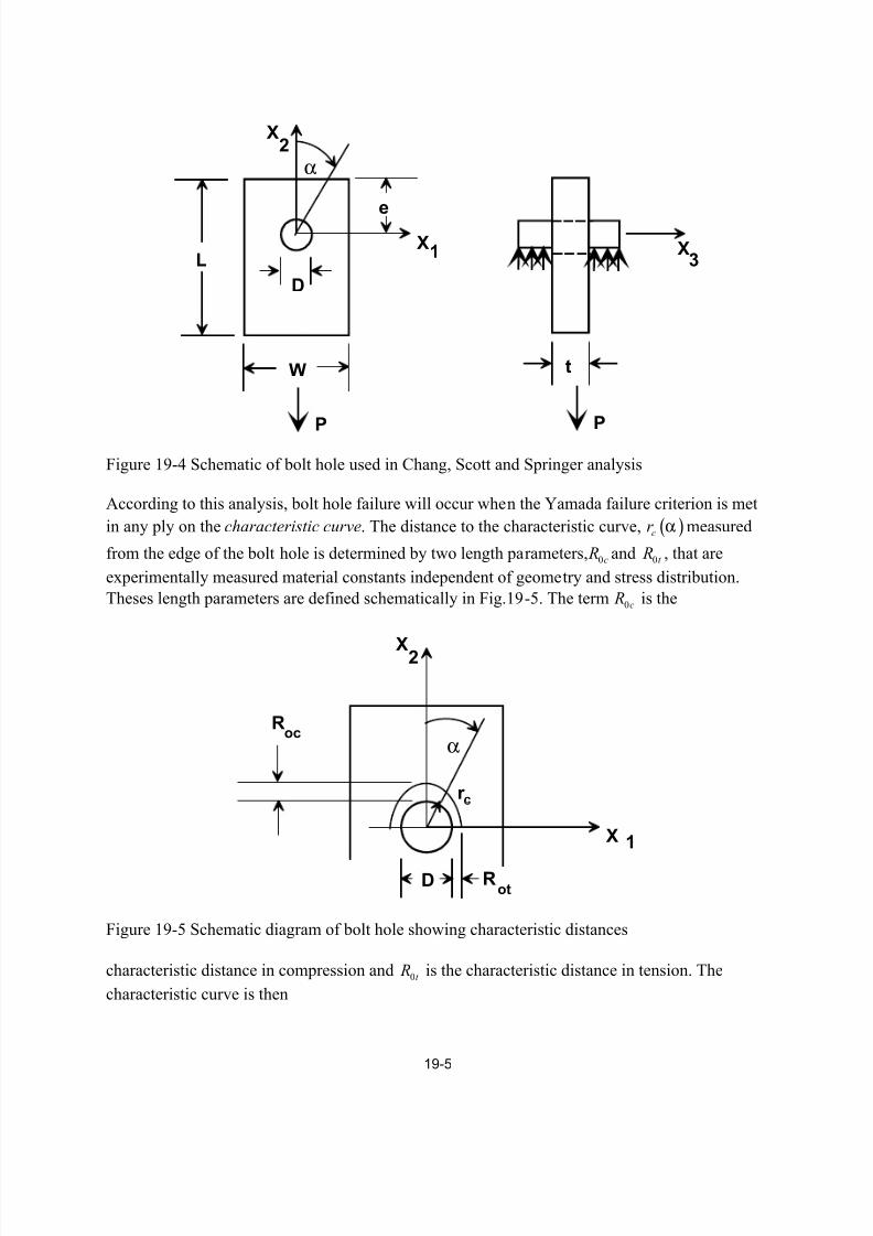
Chang, Scott and Springer offered the following composite bolt failure analysis. A schematic
diagram of the bolt hole specimen and the critical parameters used in the analysis are shown in
Fig. 19-4. The bolt shank is loaded uniformly and symmetrically along its length in the 2 X
direction. The angle α is measures from the load direction. The failure criterion used in this
analysis was originally proposed by Yamada,
22
1 12 1c X S
σ τ + = (19.1)
where X is the strength of a longitudinal and cS is the shear strength of a symmetric cross-ply.
This criterion is a simplified Tsai-Hill criterion with the transverse and biaxial strength terms
eliminated.
7/17/2019 Composite Joining and Joints
http://slidepdf.com/reader/full/composite-joining-and-joints 5/12
19-5
e
D
L
W
P
1
2
X
X
α
P
t
X3
Figure 19-4 Schematic of bolt hole used in Chang, Scott and Springer analysis
According to this analysis, bolt hole failure will occur when the Yamada failure criterion is met
in any ply on the characteristic curve. The distance to the characteristic curve, ( )cr α measured
from the edge of the bolt hole is determined by two length parameters, 0c R and 0t R , that are
experimentally measured material constants independent of geometry and stress distribution.
Theses length parameters are defined schematically in Fig.19-5. The term 0c R is the
α
r c
R
R
X
X
2
1
Dot
oc
c
Figure 19-5 Schematic diagram of bolt hole showing characteristic distances
characteristic distance in compression and 0t R is the characteristic distance in tension. The
characteristic curve is then
7/17/2019 Composite Joining and Joints
http://slidepdf.com/reader/full/composite-joining-and-joints 6/12
19-6
( ) ( )0 0 0 cos2
c t c t
Dr R R Rα α= + + − (19.2)
where the range of
α is
2 2
π π
− ≤ α ≤.
If at any point on the characteristic curve the Yamada criterion is exceeded,
( ) ( )2 2
1 12, ,1
c c
c
r r
X S
σ τα α + =
(19.3)
the joint has failed at that point. The local stresses on the characteristic curve,
( , ), ( , ) and ( , ) x c y c xy cr r r σ α σ α τ α must be determined by numerical method.
Converting the local stresses on the characteristic curve to principal material directions then,
( )
2 2
1
2 212
( , ) ( , ) cos ( , )sin 2 ( , ) cos sin
( , ) ( , ) cos sin ( , ) cos sin ( , ) cos sin
c x c y c xy c
c x c y c xy c
r r r r
r r r r
σ α = σ α θ + σ α θ + τ α θ θ
τ α = −σ α θ θ + σ α θ θ + τ α θ − θ (19.3)
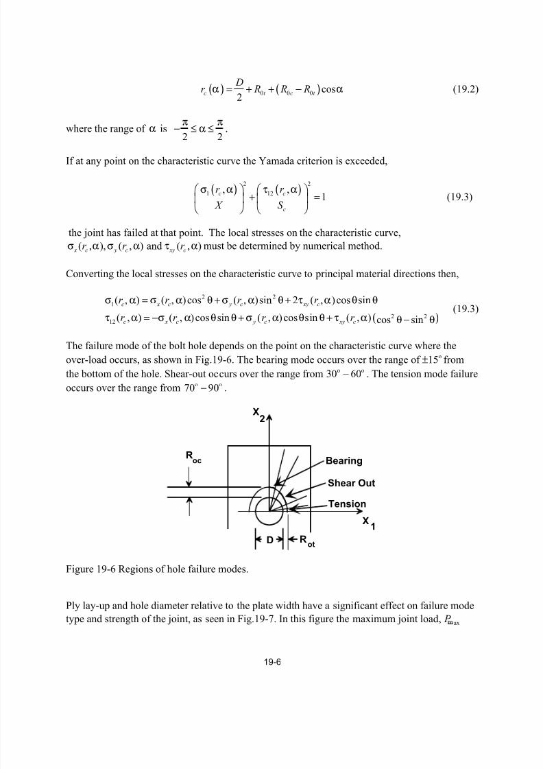
The failure mode of the bolt hole depends on the point on the characteristic curve where the
over-load occurs, as shown in Fig.19-6. The bearing mode occurs over the range of o15± from
the bottom of the hole. Shear-out occurs over the range from o o30 60− . The tension mode failure
occurs over the range from o o70 90− .
R
R
X
X
2
1
D ot
oc Bearing
Shear Out
Tension
Figure 19-6 Regions of hole failure modes.
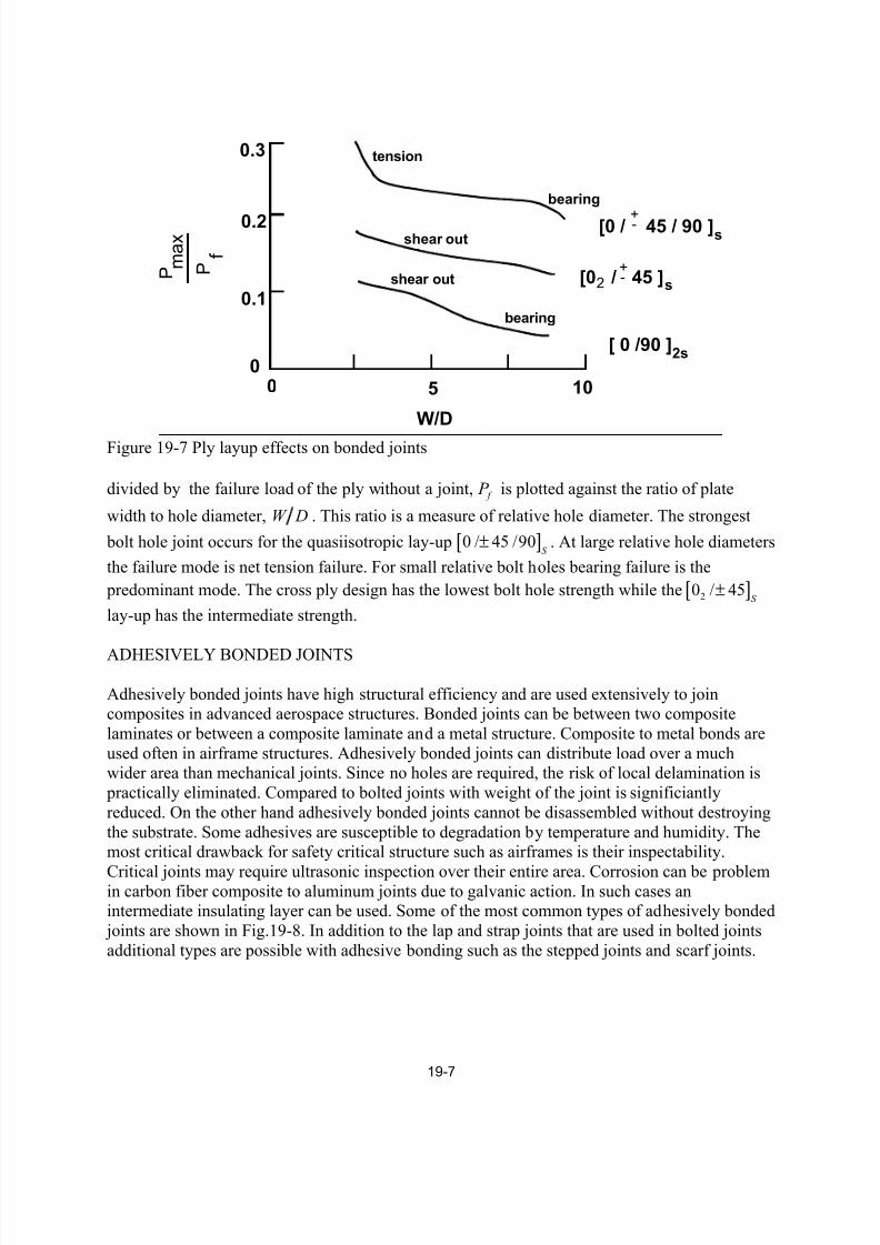
Ply lay-up and hole diameter relative to the plate width have a significant effect on failure mode
type and strength of the joint, as seen in Fig.19-7. In this figure the maximum joint load, ax P
7/17/2019 Composite Joining and Joints
http://slidepdf.com/reader/full/composite-joining-and-joints 7/12
19-7
5 100
0.3
0.2
0.1
0
W/D
P m a x
f P
tension
bearing
shear out
bearing
shear out
[0 / 45 / 90 ]
[0 / 45 ]
[ 0 /90 ]
+-
+-
2s
s
2 s
Figure 19-7 Ply layup effects on bonded joints
divided by the failure load of the ply without a joint, f P is plotted against the ratio of plate
width to hole diameter, W D . This ratio is a measure of relative hole diameter. The strongest
bolt hole joint occurs for the quasiisotropic lay-up [ ]0 / 45 /90S
± . At large relative hole diameters
the failure mode is net tension failure. For small relative bolt holes bearing failure is the
predominant mode. The cross ply design has the lowest bolt hole strength while the [ ]20 / 45S
±
lay-up has the intermediate strength.
ADHESIVELY BONDED JOINTS
Adhesively bonded joints have high structural efficiency and are used extensively to joincomposites in advanced aerospace structures. Bonded joints can be between two composite
laminates or between a composite laminate and a metal structure. Composite to metal bonds are
used often in airframe structures. Adhesively bonded joints can distribute load over a muchwider area than mechanical joints. Since no holes are required, the risk of local delamination is
practically eliminated. Compared to bolted joints with weight of the joint is significiantly
reduced. On the other hand adhesively bonded joints cannot be disassembled without destroying
the substrate. Some adhesives are susceptible to degradation by temperature and humidity. Themost critical drawback for safety critical structure such as airframes is their inspectability.
Critical joints may require ultrasonic inspection over their entire area. Corrosion can be problemin carbon fiber composite to aluminum joints due to galvanic action. In such cases anintermediate insulating layer can be used. Some of the most common types of adhesively bonded
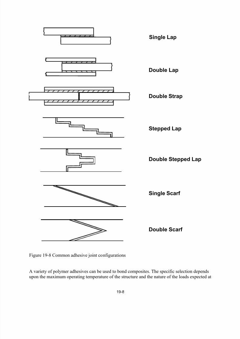
joints are shown in Fig.19-8. In addition to the lap and strap joints that are used in bolted joints
additional types are possible with adhesive bonding such as the stepped joints and scarf joints.
7/17/2019 Composite Joining and Joints
http://slidepdf.com/reader/full/composite-joining-and-joints 8/12
19-8
Double Lap
Double Strap
Stepped Lap
Double Stepped Lap
Single Scarf
Double Scarf
Single Lap
Figure 19-8 Common adhesive joint configurations
A variety of polymer adhesives can be used to bond composites. The specific selection dependsupon the maximum operating temperature of the structure and the nature of the loads expected at
7/17/2019 Composite Joining and Joints
http://slidepdf.com/reader/full/composite-joining-and-joints 9/12
19-9
the joints. Table 19-1 lists some of the more commonly used adhesives. High strength adhesives
tend to be brittle, therefore lower strength, flexible adhesives may be preferred if impact loads
are expected or high displacements are required. Usually the higher the operating temperature ofthe adhesive the greater is the cost.
Table 19-1 Polymer adhesives
Type Temp Limit Cure Temp Use
Epoxy Polyamide 200 RT-200 General
Epoxy Amine 400 RT-300 General
Epoxy Phenolic 600 325 High TempPolyester 300 RT General
Silicone 600 RT HT, Flexible
Polyimide 900 350 HT
Acrylic 300 RT Polyester
Rubber 400 RT FlexiblePolyurethane 250 RT Flexible
Cyanoacrylates 475 RT Strong, Brittle
Strength of adhesively bonded joints
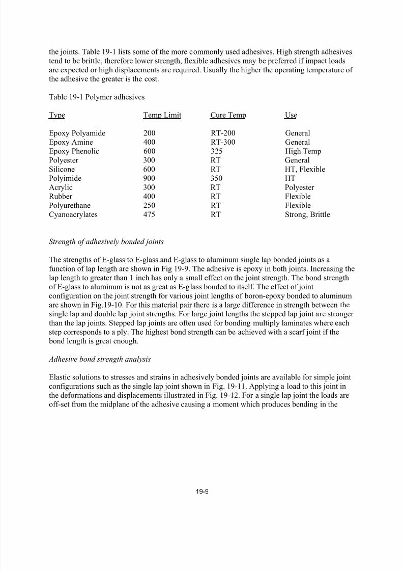
The strengths of E-glass to E-glass and E-glass to aluminum single lap bonded joints as a
function of lap length are shown in Fig 19-9. The adhesive is epoxy in both joints. Increasing the
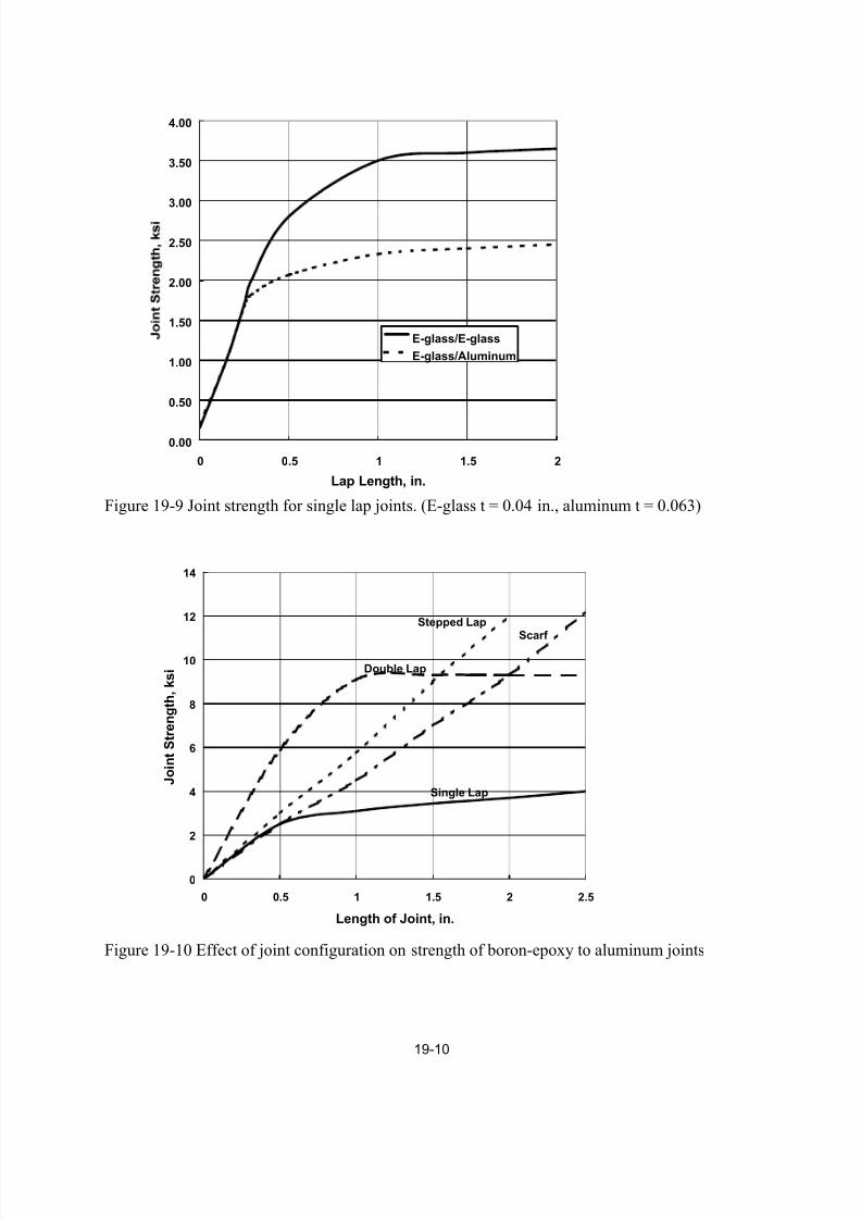
lap length to greater than 1 inch has only a small effect on the joint strength. The bond strengthof E-glass to aluminum is not as great as E-glass bonded to itself. The effect of joint
configuration on the joint strength for various joint lengths of boron-epoxy bonded to aluminum
are shown in Fig.19-10. For this material pair there is a large difference in strength between thesingle lap and double lap joint strengths. For large joint lengths the stepped lap joint are stronger
than the lap joints. Stepped lap joints are often used for bonding multiply laminates where each
step corresponds to a ply. The highest bond strength can be achieved with a scarf joint if the bond length is great enough.
Adhesive bond strength analysis
Elastic solutions to stresses and strains in adhesively bonded joints are available for simple joint
configurations such as the single lap joint shown in Fig. 19-11. Applying a load to this joint in
the deformations and displacements illustrated in Fig. 19-12. For a single lap joint the loads areoff-set from the midplane of the adhesive causing a moment which produces bending in the
7/17/2019 Composite Joining and Joints
http://slidepdf.com/reader/full/composite-joining-and-joints 10/12
19-10
0.00
0.50
1.00
1.50
2.00
2.50
3.00
3.50
4.00
0 0.5 1 1.5 2
Lap Length, in.
E-glass/E-glass
E-glass/Aluminum
Figure 19-9 Joint strength for single lap joints. (E-glass t = 0.04 in., aluminum t = 0.063)
0
2
4
6
8
10
12
14
0 0.5 1 1.5 2 2.5
Length of Joint, in.
J o i n t S t r e n g t h ,
k s i
Single Lap
Double Lap
Stepped Lap
Scarf
Figure 19-10 Effect of joint configuration on strength of boron-epoxy to aluminum joints
7/17/2019 Composite Joining and Joints
http://slidepdf.com/reader/full/composite-joining-and-joints 11/12
19-11
h
L
t
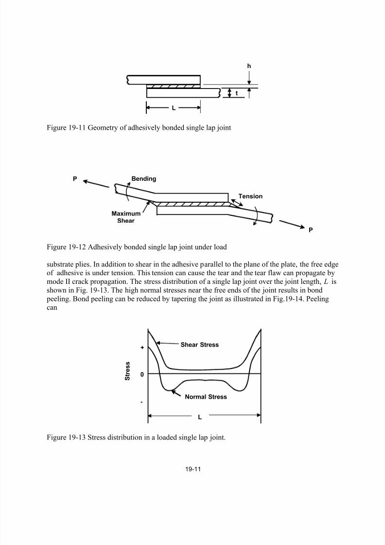
Figure 19-11 Geometry of adhesively bonded single lap joint
P
P Bending
Tension
MaximumShear
Figure 19-12 Adhesively bonded single lap joint under load
substrate plies. In addition to shear in the adhesive parallel to the plane of the plate, the free edgeof adhesive is under tension. This tension can cause the tear and the tear flaw can propagate by
mode II crack propagation. The stress distribution of a single lap joint over the joint length, L is
shown in Fig. 19-13. The high normal stresses near the free ends of the joint results in bond
peeling. Bond peeling can be reduced by tapering the joint as illustrated in Fig.19-14. Peelingcan
0
+
-
S t r e s s
L
Shear Stress
Normal Stress
Figure 19-13 Stress distribution in a loaded single lap joint.
7/17/2019 Composite Joining and Joints
http://slidepdf.com/reader/full/composite-joining-and-joints 12/12
19-12
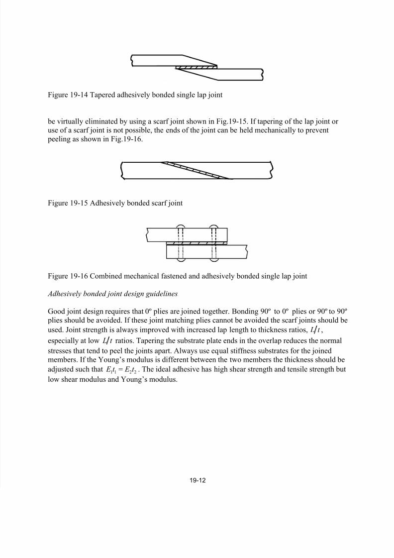
Figure 19-14 Tapered adhesively bonded single lap joint
be virtually eliminated by using a scarf joint shown in Fig.19-15. If tapering of the lap joint oruse of a scarf joint is not possible, the ends of the joint can be held mechanically to prevent
peeling as shown in Fig.19-16.
Figure 19-15 Adhesively bonded scarf joint
Figure 19-16 Combined mechanical fastened and adhesively bonded single lap joint
Adhesively bonded joint design guidelines
Good joint design requires that 0º plies are joined together. Bonding 90º to 0º plies or 90º to 90º
plies should be avoided. If these joint matching plies cannot be avoided the scarf joints should be
used. Joint strength is always improved with increased lap length to thickness ratios, L t ,
especially at low L t ratios. Tapering the substrate plate ends in the overlap reduces the normal
stresses that tend to peel the joints apart. Always use equal stiffness substrates for the joined
members. If the Young’s modulus is different between the two members the thickness should be
adjusted such that 1 1 2 2 E t E t = . The ideal adhesive has high shear strength and tensile strength but
low shear modulus and Young’s modulus.