Embed Size (px)
Citation preview

COMPOSITE OVERWRAPPED PRESSURE VESSEL (COPV)STRESS RUPTURE TESTING
Nathanael J. Greene (') , Regor L. Saulsberry(' ) , Mark R. Leifeste (3) , Tommy B. Yoder(4),Chris P. Keddy (s), Scott C. Forth (6) Rick W. Russell(')
NASA Johnson Space Center White Sands Test Facihi y, P.O. Box 20, Las Cruces, NM 88004, U.S.A.,Email: [email protected]
(2) NASA Johnson Space Center id'hite Sands Test Facihi y, P.O. Box 20, Las Cruces, NM 88004, U. S.A,Email: RegoT-.L.Saulsberi),,@nasa.gov
(3)NASA Johnson Space Center ff7aite Sands Test Facility, NASA Test and Evaluation Contract.,P.O. Box 20, Las Cruces, NM 88004, U.S.A., Email: [email protected]
(4)NASA Johnson Space Center Tf hite Sands Test Facility, NASA Test and Evaluation Contract.,P.O. Box 20, Las Cruces, NM 88004, U.S.A., Email: [email protected]
(5)NASA Johnson Space Center Tf hite Sands Test Facility, NASA Test and Evaluation Contract.,P.O. Box 20, Las Cruces, NM 88004, U.S.A., Email: Christophei-.P.Keddj,,@naso.gov(6> NASA Johnson Space Center, 2101 NASA Road 1, Houston, TX 77058-3696, U.S.A,
Email: [email protected](7) NASA Kennedy Space Center, FL 32899-0001, U.S.A, Email: Richard. [email protected]
ABSTRACT
This paper reports stress rupture testing of Kevlar®composite overwrapped pressure vessels (COPVs) atNASA White Sands Test Facility. This 6-year testprogram was part of the larger effort to predict andextend the lifetime of flight vessels. Tests wereperformed to characterize control parameters for stressrupture testing, and vessel life was predicted bystatistical modeling. One highly instrumented 102-cm(40-in.) diameter Kevlar COPV was tested to failure(burst) as a single-point model verification. Significantdata were generated that will enhance development ofimproved NDE methods and predictive modelingtechniques, and thus better address stress rupture andother composite durability concerns that affect pressurevessel safety, reliability and mission assurance.
1. INTRODUCTION
NASA Johnson Space Center (JSC) White Sands TestFacility (WSTF) has been involved since 1978 in aneffort to develop test data for understanding failuremechanisms that affect composite pressure vessels andstructures. WSTF has been actively working nationallyand internationally to promote development ofcomposite technology by fillin g data gaps that affectsafety, reliability, and mission goals [1].
Much effort has recently been invested in developingdata for safe use of Kevlar® ' composite overwrappedpressure vessels (COPVs) because they have severalfailure mechanisms that must be controlled to ensuresafe use from manufacturing to decommissioning.Failure mechanisms for COPVs include mechanical
Kevlar is a registered trademark of E.I. de Pont de Nemoms.Wilmington. Delaware.
damage, stress rupture (composite damage progression),fluid attack, corrosion, fatigue crack growth, linerbuckling, liner and overvrap manufacturing flaws;thermal environments, overstress, and micro-meteoroidand orbital debris impact [2].
This paper reports an investigation of the stress rupturefailure mechanism as it occurs in Kevlar COPVs.Several COPVs were tested to determine parameters fora final stress rupture to failure test of one 102-cm(40-in.) vessel (SiN 007) to verify model predictions.Actual vessel behavior was compared to the modelpredictions, and significant data were generated. Thestress rupture failure mechanism is characterized bydamage progression with time in the composite under asustained load. The damage evolution of stress rupturecan degrade strength such that the burst of a pressurevessel occurs at operating pressure.
2. BACKGROUND
Investigation into the stress rupture failure mechanismfor Kevlar in COPVs began during the development ofthe technology in the early 1970s. Kevlar overwrappedrubber-lined vessels were developed and tested in 1974by Lawrence Livermore National Laboratories (LLL) oncontract to NASA Lewis Research Center (now NASAGlenn Research Center (GRC)) [2]. Kevlar 10.80 cm(4.25 in.) diameter (0) spheres were developed andstress rupture tested at LLL in 1978 [3,4]. Also in 1978,Kevlar 8.6 cm (3.4m'.) 0 x 26.9 cm (10.6 in.) vessels(Fig.l) were stress-rupture tested at NASA WSTF [5],and 26.04 cm (10.25 in.) 0 spheres were stress rupturetested at JSC [6]. Time, temperature, and pressure datawere collected on Kevlar COPVs so that predictions of areliable lifetime under sustained load could be made.The test data collected demonstrated a large scatter in

wstf0580-0703Figure 1. The first flight-rated COPV stress
rupture tests were at WSTF
the time-to-failure data. Further testing, using the latestdevelopments in nondestructive evaluation (NDE) andcomputerized predictive models, was needed to betterunderstand Kevlar COPV stress rupture failure.
Phoenix at Cornell University [7], Heydorn at NASA-JSC [8], Glaser at LLL [9], and Cavanaugh et al. [10]and Robinson [11] at The Aerospace Corporation.
The Phoenix model was used for life prediction and testparameter selection for the S!N 007 burst test. ThePhoenix model is formulated with conditional reliabilityallowing the model to be re-baselined at various points.This approach for calculation of probability of failureprovides different results than the straight reliabilityapproach, as can be seen in Fig. 2. Equations 1 and 2 aresimplified representations of the Phoenix Model II forthe standard and conditional reliability life estimates,where:
F(t,o) is reliability as a function of time at pressureand fiber stress level
t t is the time at one stress level up to At where anotherstress level is applied
tc,,Yf is a calculated reference time6opi; 6ref and 6op2 ; a,.ef are operating stress ratiosP is the power law exponent( is the Weibull shape parameter
P F R
F(t, o-) = 1 — exp — (toes 1(/\ 6.1^ +t41 ` 6IP J (1)
3. EXPERIMENT DESIGN
Testing of Kevlar COPVs at NASA WSTF from 2004 to2010 was a part of the effort to predict and extend thelifetime of flight vessels. The program included testingof five 102 cm (40 in.) 0 COPVs (S/N 002, 006, 007,009, and 011), two 66 cm (26 in.) 0 COPVs (S/N 001and 005). and three 56 cm (22 in.) O COPVs (S/N 014,022, and 027).
Pressure cycling and burst tests were performed on theCOPVs to characterize control parameters for stressrupture testing on flight articles. Upon completion of thecontrol parameter tests, highly instrumented stressrupture testing of the 102 cm (40-in.) O COPY S/N 007was performed to failure as a single-point modelverification.
3.1. Stress Rupture Models
The large scatter in the time-to-failure data for pressurevessels requires statistical modeling to determine themean time to failure at load and temperature. Models forestimation of stress rupture lifetime for Kevlar COPVshave been developed based on power law and Weibulland Pareto distributions, and result in differingpredictions of vessel lifetime. Models reviewed in theexperiment design for this test included those by
P Tl(2)/ ^P
tl opl
'N'p2
t, oplF(t, o)=1-exp -P
++ 1(r f 0-re r=. l
17_fl_,-f 07-f
Equations. 1 and 2 have been used to generate the resultsin Fig. 2.
3.2. Model Verification
Because of the large scatter in data requiring statisticalmodeling, the standard "elephant test" approach wasapplied for comparing the model predictions to the testdata. Elephant tests are also referred to as design limittests or design margin tests. Allegorically, this testingapproach is like having an elephant step on a product tosee if it passes or fails a criteria [12].
The test success criteria for model verification werebased on the Phoenix Model II lifetime predictions forthe 95 percent confidence interval for low, mean, andhigh estimates for failure (burst) of the test vessel(Fig. 3).

Data Scatter
Comparison of Approaches for Reliability Calculations
1.000I
0.995 — — — — — - — r-- — — — - — — — — — — r — — — — — — — — — — — r — — — — — — I — — — — — — T — — — — —
0.990 -----7------r-- — — y — — — — — — r -- — — — - I — — --r— — — — — — I - - - - - - t-----
0.985 — — — — — y — — — — — — r — — — — — y — — — — r ----- -I------ ------I----- - t-----
I I 1 1
0.980 -----1------F-----^---- +----- -1------+— --- -1------+-----
0.975 — — — — — - — — — — — — — — — — — - — — — — — — +— ----1------+---- —1------+-----
I I I I I II
0.970 ------4-------------4------4------ ------4-------I— ----4------A I I I I I I I
E0.965 — — — — — - — — — — — — — — — — — - — — — — — — - — — — — — —I— — -- — - — — — — — — I --- -------N I I I I I I I I
0.960 _____J______ L_____ J______ L______I_____ L______I_____
I I I I I I0.955 _____J______ L_____ J______L______I______ L_ ____I______1_
I I I I I I I I
tr 0.950 -----j------j------1------L------------L---- -------T----
I I I I I I I
0.945 — — — — — - — — — — — — — — — — — — — — — — — — — — — — — — — — — — — — — — — — — -----
I I I I I I I I
0.940 — — — — — - — — — — — — ------ — — — — — — — — — — — — — — — — — — ------ 1 ---
I I I I I I I I
0.935------- — — — — — — — — — — -------- — — — — — -- — — — — — — — — — — — — -- — — — — — -----
I I I I I I I
0.930 -- - - - - - - - - - r -------- - - - - j -- - - - - - - - - - - T -- - - - - - - - - - - T - ---
0.925
0.920
2000 4000 6000 8000 '10000 12000 14000 16000 18000
Time at Pressure, hours
—$— Standard Reliability —0— Conditional Reliability: Continious Rebaseline — — Contitional Reliability: Baseline 9k hours
Figarre 2. Straight reliability, conditional reliability at each pressurization and conditional reliabilitythat re-baselines once and calculates future use relative to that baseline
Green signifies the case that thevesselsurpasses the population and doesnot fail
Burst static strength anchor point
Stress Rupture Model
Yellow signifiesvessel that fails within themodelmean prediction
Orange signifiesvessel that fails with little orno margin ahead of thefleet vessels
TimeFigure 3. Single point stress rupture elephant test

deg
Figure 6 Laser profilometry liner ripples
4. TEST SYSTEM
Stress rupture testing of S/N 007 was conducted inthe WSTF Hazardous Fluids Test Area in TestCell 862. The test cell is 2.0 lb TNT blast-rated andhas dual heating and cooling units to control thetemperature of the vessel and test system to withinf 2.8 °C (5 °F). The instrumentation and pressuresystem is remotely controlled to protect personnelfrom stored energy. The test cell also providesdedicated power backup to ensure testing is notcompromised. Fig. 4 is a photograph of the test celland backup generator.
11
Figure 4. Test Cell 862
The test system employs a high volume pump system(103 MPa (15,000 psig) rated) and a metering pumpsystem for fine pressure adjustments.
A thermal control system inside the test vesselenclosure provides thermal stability to f 1.1 °C(2 °F). Thermal gradients around the vessel wereminimized to ensure known test conditions for theoverwrap. Fig. 5 shows some thermal results fromaround a pressure vessel.
4.1. Nondestructive Evaluation
Multiple NDE methods were applied to detennine thepre-test condition of S/N 007, including visualinspection per ANSI/AIAA S-081 [13],thermography, shearography, exterior laserprofilometry and videoscope. Equipment and amethodology were developed at WSTF to performinternal laser profilometry for assessment of bucklesand liner-to-overwrap bonding integrity. Fig. 6 showsa sample of laser profilometry results on a vessel,with 0 decrees indicating the weld. The internal laserprofilometry data collected is traceable to NationalInstitute of Standards and Technology (KIST)standards and has a sensitivity of f 0.005 cm(0.002 in.). An example of liner ripple data detectedwith this technique is shown in Fig. 6.
deg
0 2 4 8 8 10 '..90 2.95 3.00 3.05 3.10
LVI - Volts Profile Radius - Inches
Figure 5. Vessel thermal environment (no fluid)

4.2. Instrumentation
Test vessels used for parameter development werehighly instrumented with strain gauges, fiber opticBragg gratings (FOBG), linear variable displacementtransducers, girth cables, Raman spectroscopy,pressurized thennograpy, ovenvrap and liner eddycurrent thickness monitors, internal volume; acousticemission, audio, high speed and 30-frame/second video,and full field strain measurement. S/N 007 wasinstrumented with all these listed except FOBG.
WSTF partners from NASA JSC, GRC, LangleyResearch Center (LaRC) and Marshall Space FlightCenter (MSFC) brought their expertise to the programand worked with I'STF to gather specialized test data.LaRC was responsible for analysis of acoustic emissionand eddy current data: GRC was responsible for Ramanspectroscopy full field strain, and MSFC wasresponsible for FOBG data. WSTF was responsible foranalysis of all primary data including pressure,temperature, strain, boss linear displacement, volumetricgrowth, and diametrical changes.
A sample photo of a vessel with instrumentationinstalled prior to test is shown in Fig. 7.
wstf1105e08998Figure 7. Typical Kevlar-epoxy vessel pre-test
instrumentation
5. TEST RESULTS
The S/N 007 COPV, tested in stress rupture to failure,exhibited a burst failure mode after 0.9 years with a peakof 1.1 times maximum expected operating pressure andat a temperature of 79 °C (175 °F) (within temperaturecertification). The vessel exceeded the 95 percentconfidence interval high prediction calculated by the
stress rupture model. Figure 8 shows the S/N 007 vesselafter hydraulic stress rupture testing.
All primary data were successfully collected, and dataanalysis from the test program is underway. Secondarydata have been provided to team members for analysis.Final reports will be published on the results
wstf1105e11453Figure 8. Kevlar vessel upon completion of stress
rupture test
6. Breakthroughs in Testing
Several breakthroughs in NDE physical standards andtest approach methodology for composite pressurevessel testing resulted from the COPY stress rupturetesting program at WSTF.
NDE developments included:• Raman spectroscopy for direct strain
measurement• Physical standards for laser shearography and
thermography• Laser profilometry for inspection of liner to
overwrap interface
Test approach improvements included:• Active pressure and temperature management
control to f 0.6 °C (1 °F) and f -35 kPa (-5 psig)• Stepped stress rupture test method for COPVs• COPV health check recertification methodology
7. CONCLUSIONS
New techniques for NDE structural health monitoringare being developed as a result of the data collectedfrom the methods employed during this test program.The S/N 007 vessel exceeded model predictions,resulting in a positive result for the elephant test. Thevariance in the test results from the model predictionindicates that further work is needed in order to improvemodel predictions for Kevlar epoxy vessels.

8. FUTURE WORK
Significant data exist on Kevlar epoxy in stress rupture;however, model improvements are needed. For otherfiber types such as carbon and polybenzoxazole, lessdata are available. As a result, stress rupture modelaccuracy on COPVs and composite pressurizedstructures is unknown. However, in this programsignificant data were obtained as predictions were testedto compare vessel behaviour to the model. These dataare available to feed back into all models for futurepredictions. WSTF is working with NASA, the U.S.Departments of Defense, Energy, and Transportation,the Federal Aviation Administration, and industrypartners worldwide to answer questions about stressrupture and other composite durability concerns thataffect safety, reliability and mission assurance.
9. REFERENCES
1. Greene, N. J. WSTF Composite Pressure Vessel andStructure Summit (2009): NASA White Sands TestFacility, Las Cruces, NM,http://www.nasa. gov/centers/wstfnews/safetysu
(accessed 5/3/2010).
2. Greene, N. J. (2009). "Composite OverwrappedPressure Vessels." Chapter 17.5 in Safety Designfor Space Systems (Eds. G. Musgrave, A. Larsen,T. Sgobba), Elsevier Publications (elsevier.com ,accessed 4/28/10).
3. Chiao, T., E. Hamstad, E. Jessop, and R. Tolland(1978). High-Performance Fiber/Epoxy CompositePressure Vessels. Report UCRL-52533, LawrenceLivermore National Laboratory, Livermore, CA.
4. Tolland, W., R. Sanchez, and D. Freeman (1978).Stress-Rapture Life of Kevlar/Epoxy SphericalPressure Vessels. Report UCID-17755, LawrenceLivermore National Laboratory, Livermore, CA.
5. Luper, A., L. Linley, and D. Pippen (1982). PortableOxygen System Bottle Accelerated Aging. TR-237-
001, NASA Johnson Space Center White SandsTest Facility, Las Cruces, NM.
6. Schmidt, W. and G. Ecord (1983). Static Fatigue Lifeof Kevlar Arimid/Epoxy Pressure Vessels at Roomand Elevated Temperatures. AIAA Paper number83-1328, Propulsion Conference of the AmericanInstitute of Aeronautics and Astronautics, Reston,VA.
K. Cameron, L. Grimes-Ledesma, S. Phoenix,P. Murthy, J. Thesken, and R. Saulsberry. OrbiterKevlar/Epoxy Overwrapped Pressure Vessel FlightRationale Technical Assessment Report. RP-07-34(restricted access), NASA Engineering SafetyCenter,http://www.nasa. gov/offices/nest,,'home/index.html(accessed 5/3/2010).
8. R. P. Heydorn and T. English (2006). Estimates of theConditional Reliabilitv of COPVs Based on DoE-Dupont and LLNL Time-to-Failure Data. SAIL,Fairfax County, VA.
9. R.E. Glaser (1983). Statistical Analysis of Kevlar49/Epoxy Composite Stress-Rapture Data. UCID-19849, Lawrence Livermore National Laboratories,Livermore, CA.
10. M. Cavanaugh, J. Chang, S. Ruth, and S. Sallam(2005). Space Shuttle COPVs Life ExtensionAssessment Draft. The Aerospace Corporation, ElSegundo, CA.
11. E. Robinson (2005). Reliability Analysis and LifeExtension Forecast of Kevlar COPY in the STS-Orbiter - An Independent Assessment Draft. TheAerospace Corporation, El Segundo, CA.
12.Nelson, W. (1990). Accelerated Testing StatisticalModels, Test Plans and Data Analyses. WileyPublishers, New York.
13.ANSI/AIAA S-081A (2006). Space Systems -Composite Overwrapped Pressure Vessels(COPVs), American Institute of Aeronautics andAstronautics, Reston, Virginia.

`t
' 4th IAASS Conference - Making Safety Matter
' Composite Overwrapped Pressure VesselStress R Testing
NASA JSC White Sands Test Facility
Nathanael J. GreeneT 575-525-7601 [email protected]

Overview
I I rM;M IWA
The first flight-ratedCOPV stress rupturetests were at WSTF
• NASA Johnson Space Center (JSC) WhiteSands Test Facility (WSTF) is a key leader inComposite Overwrapped Pressure Vessel(COPV) research- Since 1978, WSTF has been developing test
data for understanding failure mechanisms thataffect COPVs and structures
- WSTF works with NASA, the U.S. Departmentsof Defense, Energy, and Transportation, theFederal Aviation Administration, and industrypartners worldwide to investigate stress ruptureand other composite durability concerns thataffect safety, reliability, and mission assurance.
2

0 CA --^CD-nA NQ OO
CQ ^N nvo
^oNCD
<DNNC
fD
CfDNNCD
a1II.
CAC
A
C
Overview (cont'd)
- In 2009, WSTF hosted the first Composite Pressure Vessel andStructure Summit
a
3
Fiber Reinforced Composite (FRC)2009 Summit
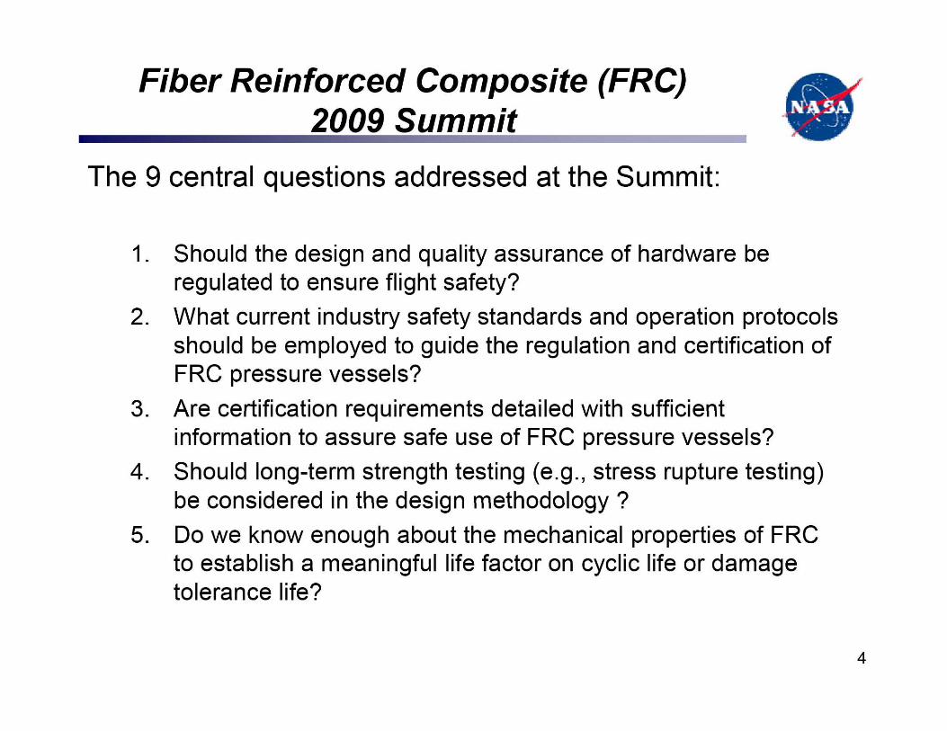
The 9 central questions addressed at the Summit:
1. Should the design and quality assurance of hardware beregulated to ensure flight safety?
2. What current industry safety standards and operation protocolsshould be employed to guide the regulation and certification ofFRC pressure vessels?
3. Are certification requirements detailed with sufficientinformation to assure safe use of FRC pressure vessels?
4. Should long-term strength testing (e.g., stress rupture testing)be considered in the design methodology ?
5. Do we know enough about the mechanical properties of FRCto establish a meaningful life factor on cyclic life or damagetolerance life?
4

Fiber Reinforced Composite (FRC)2009 Summit (cont'Y) it
6. Should we consider damage tolerance and fracture toughnessof the FRC in the design criteria to establish safe life?
7. Do we know enough about the potential failuremechanisms and coupling effects of composites forvarious ground and flight environments?
8. Should there be different design requirements for constructingresin-based FRCs when different fluids are used (i.e., gas vs.liquid) to determine long-term stress or pressure rating?
9. Who should be responsible for modifying or developingstandards that don't exist for new technology?
5

COPY Stress Rupture Testing Program
• A 6-year COPY testing program (2004-2010) at WSTFresulted in several breakthroughs for test approach andnondestructive evaluation (NDE) testing
• Previous tests yielded large scatter in time-to-failure data• Further tests were needed with latest NDE techniques
and predictive models for life extension— Pressure cycling and burst tests characterized control
parameters for stress rupture tests on flight articles— Highly instrumented stress rupture testing of 102-cm (40-in.)
COPV S/N 007— Stress Rupture Model
• Phoenix Model II used for life prediction and test parameter selection
— Model Verification0 "Elephant test" approach
6

Phoenix Model H Approach Compared to theStraight Reliability Approach
Comparison of Approaches for Reliability Calculations
0 2000 4000 6000 8000 10000 12000 14000 16000 18000
Time at Pressure, hours
--*—Standard Reliability --W-Conditional Reliability: Continious Rebaseline --*— Contitional Reliability: Baseline 9k hours
1.000
0.995
0.990
0.985
0.980
0.975
m 0.970R
0.965ww>,
0.955
0.950
0.945
0.940
0.935
0.930
0.925
0.920
7

4JS—+
Single-Point Stress Rupture Elephant Test
Burst static strength anchorpoint
Stress Rupture Model
Subscale test ' ^i, •10data
WTI
Green signifies the case that the vesselsurpasses the population and does not fail
Yellow signifies vessel that fails within themodel mean prediction
Orange signifies vessel that fails with little orno margin ahead of the fleet vessels
Single-point elephanttest
Data Scatter
Time
s

wstf1005e08438
Test Cell 862 of the H FTA
Stress Rupture Testing of SIN 007
• WSTF Hazardous Fluids Test Area• 2.0 lb TNT blast-rated• System temperature controlled to within ± 3 °C (5 °F)• Instrumentation and pressure remotely controlled• High volume pump system 103 MPa (15,000 psig) rated• Thermal control of 1 °C (2 °F) inside vessel enclosure
Thermal gradientsaround the vesselminimized toensure known testconditions for theoverwrap
9

Nondestructive Evaluation
• Visual inspection perANSI/AIAA S-081
• Thermography• Shearography• Exterior laser profilometry
and videoscope• Internal laser profilometry
developed at WSTF• Assessment of buckles and
liner-to-overwrap bondingintegrity
deg
0 2 46 8 10 ?_90 2.95 3.00 3.05 3.10
LVI -Volts Profile Radius - Inches
50deg
Laser profilometry liner ripples
10

wstf1105e08998
Typical Kevlar-epoxy vesselpre-test instrumentation
I itNondestructive Evaluation (cont-d)
• Instrumentation— Strain gauges— Fiber optic Bragg gratings (FOBG)
(except S/N 007)— Linear variable displacement
transducers— Girth cables— Raman spectroscopy— Pressurized thermography— Overwrap and liner eddy current
thickness monitors— Internal volume— Acoustic emission— Audio— High-speed and 30 fps video— Full field strain measurement
11

Test Team
• Expertise from various NASA Centers:— Data expertise:
• NASA White Sands Test Facility• NASA Johnson Space Center• NASA Glenn Research Center• NASA Langley Research Center• NASA Marshall Space Flight Center
— Acoustic emission and eddy current data
• NASA Langley Research Center
— Raman spectroscopy full field strain• NASA Glenn Research Center
— FOBG data• NASA Marshall Space Flight Center
12

Test Results
• S/N 007 COPV tested in stress rupture to failure— Burst failure after 0.9 years
• Peak of 1.1 times MEOP at 79 °C (175 °F) (withintemperature certification)
• Exceeded 95% confidence interval high prediction ofstress rupture model
Kevlar vessel uponcompletion of stressrupture test
13

Breakthroughs for COPV Testing
• NDE developments included:— Raman spectroscopy for direct strain measurement— Physical standards for laser shearography and
thermography— Laser profilometry for inspection of liner to overwrap
interface
14

Breakthroughs for COPV Testing (contd) it• Test approach improvements included:
— Active pressure and temperature management controlto ± 0.6 °C (1 °F) and ± -35 kPa (-5 psig)
—Stepped stress rupture test method for COPVs— COPV health check recertification methodology
• New techniques for NDE structural healthmonitoring are being developed as a result ofdata obtained from the methods used during thistest program.
15

Future Work
• Significant data exist on Kevlar epoxy COPVs instress rupture; however, model improvementsare needed.
• Less data are available for other fiber types suchas carbon and polybenzoxazole.
• Significant data from this stress rupture testprogram are available to feed back into allmodels for future predictions.
• WSTF works with partners worldwide toinvestigate composite durability concerns thataffect safety, reliability, and mission assurance.
16
Point of Contact
NASA White Sands Test Facility
Nathanael J. Greene575-525-7601
17