Embed Size (px)
Citation preview

Proc. 2017 Annual Meeting of the Electrostatics of America 1
Comprehensive Modeling of Superficial
Dust Removal via Electrostatic and
Dielectrophoretic Forces in Extraterres-
trial Exploration Mission
Jesus. A. Dominguez1, James R. Phillips III
2, Paul J. Mackey
2, Michael D. Hogue
2,
Michael R. Johansen2, Rachel E. Cox
2, Carlos. I. Calle
2
1Vencore, Kennedy Space Center, FL 32899, email: [email protected]
2 NASA Electrostatics and Surface Physics Laboratory, Kennedy Space Center, FL
32899
Abstracts- The Electrostatics and Surface Physics Laboratory (ESPL) at NASA Kennedy
Space Center has developed a dust mitigation technology that uses electrostatic and
dielectrophoretic (DEP) forces to disperse and remove the dust already deposited on surfaces
preventing the accumulation of dust particles approaching or already deposited on those sur-
faces. Dust removal during lunar and Martian exploration activities is of primary importance
for the success of both robotic and human exploration of Mars and the moon. This paper
describes a rigorous 3D model developed at the ESPL that uses and couples two physics, elec-
tromagnetism and particle tracing, both in transient mode to forecast not only the charging
process of the particles (electrostatic and dielectric dipole moment) but also their motion and
displacement under an electromagnetic field. The electromagnetic field is generated by sup-
plying a three-phase voltage to an array of parallel conductors embedded in a dielectric sub-
strate. COMSOL Multiphysics®, a general-purpose software platform used for modeling
and simulating physics-based problems, was used to model and simulate these two physics
that are present in different phases, continuous (electromagnetism) and discreet (particle
tracing). The model is aimed at optimizing the implementation of the dust mitigation technol-
ogy developed at the ESPL in terms of the geometry of the conductor array, power require-
ments, and particle removal efficiency.
I. INTRODUCTION
Future manned and unmanned extraterrestrial missions will face a vast number of chal-
lenges that include removal of dust particles from solar panels, thermal radiators, analysis
and exploration equipment, astronaut’s protection items, such as suit gloves, visors and
attached gears. Dust will have a negative impact on the efficiency of solar panels, thermal
radiators, and exploration/analysis equipment. ESPL is developing an active dust mitiga-
tion technology that has demonstrated to be especially effective in the removal of dust
particles from surfaces and in the prevention of the accumulation of those particles on
such surfaces [1]. This technology basically creates an Electro-Dynamic Traveling Wave

Proc. 2017 Annual Meeting of the Electrostatics of America 2
(EDTW) at the surface using a series of parallel conductors embedded in the surface and
connected to an AC source that generates the EDTW on the surface capable of charging
particles and polarizing uncharged particles, yielding electrostatic and dielectrophoretic
forces on polarized and charged particles respectively, and acting as a contactless con-
veyor to transport and remove the charged particles.
The authors have built a rigorous 3D-transient model on this dust removal technology by
successfully coupling in transient mode the two different physics phases present in this
dust removal technology, generation of the electrical-magnetic field and the transporta-
tion of charged and polarized particles through the EDTW generated by parallel conduc-
tors embedded in the surface. These two modeled phases, that need to be coupled and
solved simultaneously in transient mode, are a discrete phase consisting of the dust
particles and a continuous phase consisting of the electrical and magnetic fields gener-
ated between and above the conductors by a multiphase AC electrical potential applied
at the end sides of the conductors.
II. BACKGROUND AND THEORY
The dust removal technology implemented by ESPL is based on the EDTW concept de-
veloped by F.B. Tatom in 1967 [2] and implemented later by Masuda in 1970 [3]. This
technique has been demonstrated experimentally by lifting and transporting charged and
polarized dust particles by electrostatic and dielectrophoretic forces respectively both
generated within the EDTW [4,5,6,7,8,9].
To generate the EDTW at the surface a series of parallel conductors are connected to a
multiphase electrical potential source to generate a traveling wave acting as a contactless
conveyor. The EDTW is generated by a AC voltage applied at the end sides of the con-
ductors having the same amplitude and angular frequency but differing in their phase.
The EDTW is generated parallel to the conductors and its direction oscillates back and
forth as the polarity of the conductors changes. The change in direction in the electrical
field yields a wave that generates forces also in different directions on charged and polar-
ized particles in the region of the electrical field [10].
The dust particles within the EDTW need to be electrically charged or polarized to expe-
rience a net force that yields the transportation of the dust particles through the EDTW. If
the dust particles are present in a gaseous atmosphere, such as air in earth and CO2 in
Mars the voltage applied to the conductors can yield such a strong electrical field that
ionizes the gas (air on earth and CO2 on Mars) charging the dust particles with ions from
the gas by either thermal diffusion or the electrical field itself. The particle charging
through the electric field is called field charging. Field charging is more dominant for
larger particles ≥ 2 μm, and for smaller particles ≥ 0.2 μm, thermal diffusion charging is
more dominant [10]. The charge of a given particle is given by
(1)
1)
2)
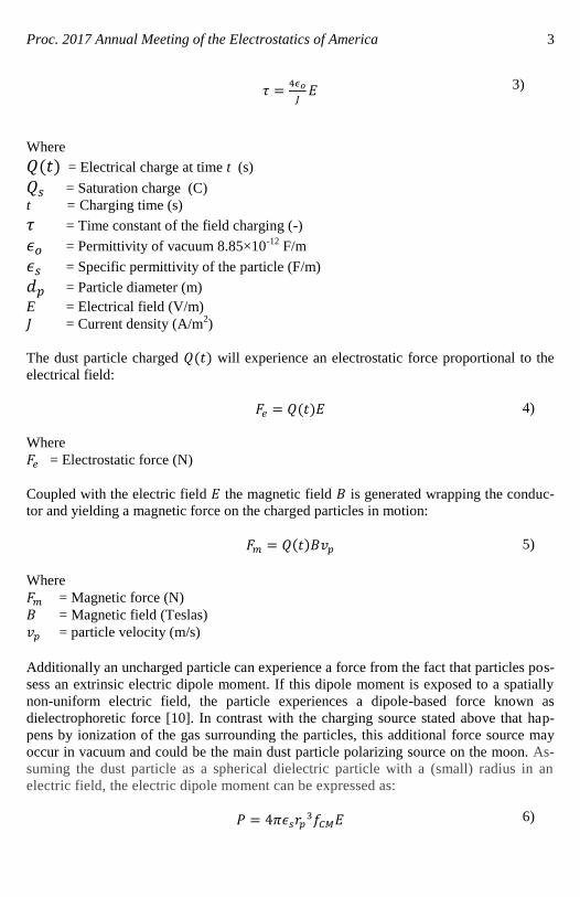
Proc. 2017 Annual Meeting of the Electrostatics of America 3
Where
= Electrical charge at time t (s)
= Saturation charge (C)
t = Charging time (s)
= Time constant of the field charging (-)
= Permittivity of vacuum 8.85×10⁻¹²
F/m
= Specific permittivity of the particle (F/m)
= Particle diameter (m)
E = Electrical field (V/m)
= Current density (A/m2)
The dust particle charged will experience an electrostatic force proportional to the
electrical field:
Where
= Electrostatic force (N)
Coupled with the electric field the magnetic field is generated wrapping the conduc-
tor and yielding a magnetic force on the charged particles in motion:
Where
= Magnetic force (N)
= Magnetic field (Teslas)
= particle velocity (m/s)
Additionally an uncharged particle can experience a force from the fact that particles pos-
sess an extrinsic electric dipole moment. If this dipole moment is exposed to a spatially
non-uniform electric field, the particle experiences a dipole-based force known as
dielectrophoretic force [10]. In contrast with the charging source stated above that hap-
pens by ionization of the gas surrounding the particles, this additional force source may
occur in vacuum and could be the main dust particle polarizing source on the moon. As-
suming the dust particle as a spherical dielectric particle with a (small) radius in an
electric field, the electric dipole moment can be expressed as:
3)
4)
5)
6)

Proc. 2017 Annual Meeting of the Electrostatics of America 4
Where
= Electric dipole moment on the particle (C.m)
= Permittivity of the medium (F/m)
= Particle radius (m)
= Mossotti-Clausius factor (-)
= Complex permittivity of the medium (F/m)
= Complex permittivity of the particle (F/m)
= Electrical conductivity of the medium (S/m)
= Electrical conductivity of the particle (S/m)
= Angular frequency
The dielectrophoretic force has a vector-valued relationship with the electric dipole and
is expressed as:
Where
= Dielectrophoretic force
Replacing (6) into (10) becomes:
As indicated in equation 10 only dust particles yielding an electric dipole moment un-
der a electrical field (equation 6) within non-uniform electrical field are subject to
dielectrophoretic force. Since the dust particle is small, its dipole moment is considered
a constant. Equation 11 shows the dependency of the electric-dipole induced force on
the gradient of the square of the magnitude of the electric field.
Non-electric forces on the dust particles, such as gravitational, buoyant, and drag forces
need to be added to compute the net force generated on charged and polarized dust parti-
cles. The more relevant of these forces are:
7)
8)
9)
10)
11)
12)

Proc. 2017 Annual Meeting of the Electrostatics of America 5
Where
= Gravitational force (N)
= Friction force (N)
= Buoyant force (N)
= Particle density (kg/m3)
= Surrounding gas density (kg/m3)
= Surrounding gas dynamic viscosity (N-s/m2)
= Particle velocity (m/s)
= Terrestrial gravitational acceleration (9.8 m/s2)
Current density , electrical and magnetic fields and included in the expressions
above are found by solving Maxwell’s equations subject to certain boundary conditions.
Maxwell’s equations are a set of equations, written in differential or integral form, stating
the relationships between the fundamental electromagnetic quantities, Electric field inten-
sity E, Electric displacement or electric flux density D, Magnetic field intensity H, Mag-
netic flux density B, Current density J, and Electric charge density ρ.
The Maxwell’s equations can be formulated in differential form or integral form. The
differential form is used in the model because it leads to differential equations that the
finite element method can handle. For general time-varying fields, Maxwell’s equations
can be written as:
Where
= Electric field intensity (N/C)
= Electric displacement or electric flux density (C/m2)
13)
14)
15)
16)
17)
18)

Proc. 2017 Annual Meeting of the Electrostatics of America 6
= Magnetic field intensity (Teslas)
= Magnetic flux density (Wb)
= Current density (A/m2)
= Electric charge density ρ (C/m3)
Equation (15) is known as Maxwell-Ampere law and equation (16) is known as Fara-
day’s law. Equations (17) and (18) are two forms of Gauss’ law: the electric and magnet-
ic form, respectively. Another fundamental equation is the equation of continuity
Out of the five equations (15) through (19), only three are independent. The first two
combined with either the electric form of Gauss’ law or the equation of continuity form
such an independent system.
To build a comprehensive model for the removal of superficial dust in extraterrestrial
exploration mission via electrostatic, magnetic, and dielectrophoretic forces we need to
solve coupled equations (1) through (19) that describe a two-phase system, a discrete
phase consisting of the dust particles (equations 1 through 14), and a continuous phase
that surrounds the dust particles (equations 15 through 19). COMSOL Multiphysics®
,
a general-purpose software platform used for modeling and simulating physics-based
problems, was used to model these interconnected two dissimilar phases and simulate
in transient mode dust particles removal on extraterrestrial surfaces. The problem of
tracking the Particles (discrete phase) and yielding the electrical and magnetic fields
(continuous phase) were formulated using two COMSOL’s modules, the Mathematical
Particle Tracing (pt) and Electrical Currents (ec) modules respectively. The discrete
phase (the particles) is assumed to be a volume fraction of the continuous phase, the
domain where the particles are located and exposed to the electrical and magnetic
fields. The mayor challenging in modeling this coupled discrete and continuous phases
is the fact that both phases need to be solved simultaneously in transient mode as the
state of the continuous phase is time-dependent having boundary conditions at the outer
end side of each conductor yielding transient multiphase electrical potential. The state
of the discrete phase (the particles) is intrinsically time dependent.
For the discrete phase (dust particles), COMSOL’s Mathematical Particle Tracing (pt)
module solves an ordinary differential equation for each component of the particle’s
position vector. This means that three ordinary differential equations are solved for
each particle in 3D, and two in 2D. At each time step, the forces acting on each particle
are queried from the computed fields at the current particle position. If particle-particle
interaction forces are included in the model, they are added to the total force. The par-
ticle position is then updated, and the process repeats until the specified end time for
the simulation is reached.
For the continuous phase (electrical-magnetic field), COMSOL’s Electrical Currents
(ec) module solves Maxwell’s equations together with material properties and bounda-
ry conditions. The equations are solved using finite element method with numerically
stable edge element discretization in along with state-of-the-art solvers.
19
Proc. 2017 Annual Meeting of the Electrostatics of America 7
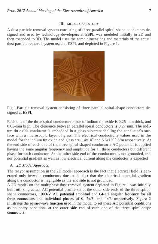
III. MODEL CASE STUDY
A dust particle removal system consisting of three parallel spiral-shape conductors de-
signed and used by technology developers at ESPL was modeled initially in 2D and
then extended to 3D. The model uses the same dimensions and materials of the actual
dust particle removal system used at ESPL and depicted in Figure 1.
Fig 1.Particle removal system consisting of three parallel spiral-shape conductors de-
signed at ESPL
Each one of the three spiral conductors made of indium tin oxide is 0.25-mm thick, and
0.05-mm high. The clearance between parallel spiral conductors is 0.27 mm. The indi-
um tin oxide conductor is embedded in a glass substrate shelling the conductor’s su r-
face with a microscopic layer of glass. The electrical conductivity values used in the
model for the indium tin oxide and glass are 1.4x10⁶ and 5.6x10
− 4 S/m respectively. At
the end side of each one of the three spiral-shaped conductor a AC potential is applied
having the same angular frequency and amplitude for all three conductors but different
phase for each conductor. As the other side end of the conductors is not grounded, mi-
nor potential gradient as well as low electrical current along the conductor is expected
A. 2D Model Approach
The mayor assumption in the 2D model approach is the fact that electrical field is gen-
erated only between conductors due to the fact that the electrical potential gradient
along the conductor is negligible as the end side is not grounded.
A 2D model on the multiphase dust removal system depicted in Figure 1 was initially
built utilizing actual AC potential profile set at the outer side ends of the three spiral-
shape connectors, 1000-V AC potential amplitud and 64-Hz angular frquency for all
three connectors and individual phases of 0, 2π/3, and 4π/3 respectively. Figure 2
illustrates the squarewave function used in the model to set these AC potential conditions
as boundary conditions at the outer side end of each one of the three spiral-shape
connectors.

Proc. 2017 Annual Meeting of the Electrostatics of America 8
Fig 2. Multiphased dust removal system via three spiral conductors bearing phases of 0,
2π/3, and 4π/3 respectively at 1000-V amplitude and 64-Hz angular frquency.
The 2D model setting shown in Figure 2, three square AC potential waveform applied at
the outer edge ends of three spiral conductors, generates a linear gradient electrical poten-
tial around the conductor's edges starting with a maximum electrical potential value at the
conductor's edge and vanishing as the distance to the conductor's edge increases to even-
tually reaches zero value. Figure 3 shows the electrical potential and the respective elec-
trical field in one particular instant. Figure 4 shows the electrical field generated at four
different instances (0, 0.025, 0.05, and 0.1 seconds respectively).

Proc. 2017 Annual Meeting of the Electrostatics of America 9
Figure 3. 2D electrical potential profile and its derived electrical field.
Fig 4. 2D electrical field profile generated during four instances, 0, 0.025, 0.08, and 0.1
seconds respectvily.
As stated above and corroborated in Figures 3 and 4, the electrical field generated at all
instants within the separation area between parallel conductors is uniformed as the re-
spective gradient of the electrical potential is linear. As stated in equation (10),
dielectrophoretic force generation is only feasible at non-uniform electrical fields allow-
ing electrostatic force to be the only electric-based force to be considered in this 2D mod-
el approach. Magnetic force is neglected in this 2D model approach as it is actually rele-
vant in 3D domains.
Electrostatic force outcome on dust particles is basically dictated by the charging time as
illustrated in Figures 5a and 5b. The trajectory and velocity of a 25-µm dust particle with
two different charging time , one as stated in equation 3 (Figure 5a) and the other one

Proc. 2017 Annual Meeting of the Electrostatics of America 10
equal to zero (Figure 5b) differ substantially as charging time determines how fast or
slow the particle gets full charge (saturation charge). When charging time is not assumed
to be zero but a function of the electrical field and the current density (equation 3) the
particle takes a shorter path but at slower velocity leading to a longer removal time, 0.115
against 0.07 seconds as shown in Figure 5. Assuming instantaneous saturation charge on
the particle (Figure 5b) leads to higher particle's velocity and shorter removal time even
though the particle takes longer path that the particle with charging time (Figure 5a).
Fig 5. Trajectory and velocity of a dust particle modeled with two charging times: a) ac-
cording to equation 3, b) 0,
Figure 6 depicts a total of 8,690 1-μm-size particles evenly distributed underneath a 2D
multiphase spiral-shape conductors, as those shown in Figure 2, to remove them. The
model was solved to estimate the trajectory of each particle and the final particle distribu-
tion within the 2D domain.
Fig 6. Initial distribution of 8,690 particles evenly dispersed throughout the spiral-shape-
conductor removal system.

Proc. 2017 Annual Meeting of the Electrostatics of America 11
Figure 7 depicts the particle removal outcome generated by the model during four differ-
ent instants, 0.0025, 0.01, 0.02, 0.05, 0.1, and 1 second respectively.
Fig 7. Model transient outcome on electrotastic removal of 8.690 particles initially
dispersed evenly as shown in Figure 6.
Collision forces, which occur when charged particles collide with other particles and
the background gas are not included in the model results illustrated in Figure 7 .
COMSOL’s Mathematical Particle Tracing (pt) module allows the inclusion of these
forces, they will be included in further studies.
B. 3D Model Approach
The 2D domain bearing the three multiphase spiral-shape conductors used above was
extruded to create an equivalent 3D domain. The boundary conditions remain basically
the same but applied to areas (for 3D domain) rather than edges (for 2D domain). The
entire 3D domain is depicted in Figure 8 and includes the basic domains, the surrounding
(air/CO2/vacuum), the spiral conductors, and the substrate that holds the spiral conduc-
tors. All the outer faces are appropriately assumed to be electrical and magnetically insu-
lated as they are away enough from the spiral-shape connectors. The current and voltage
are considered to be present in all domains while the dust particles are reduced to be pre-
sent in the two upper domains above the domain containing the conductors embedded in
the substrate.

Proc. 2017 Annual Meeting of the Electrostatics of America 12
Fig 8. 3D domains built to model removal of particles via spiral-shape conductors
Figure 9 depicts the electric potential, the electric field, and the magnetic field generated
in a given instance by the three 3D spiral-shape depicted in Figure 8. Multiphase poten-
tials are applied at the outer ends of the 3D spiral-shape conductors as illustrated in Fig-
ure 2 for 2D spiral-shaped conductors with the difference that the AC potential are set as
boundary conditions on the area ends (3D model) rather than the edge ends (2D model)
of the spiral conductors.
Fig 9. Electric potential, electric field, and magnetic field yielded by particle removal system
shown in Figure 8.
3D model yields an electrical potential gradient above the surface of the conductor gener-
ating the EDTW as depicted in Figure 10. The EDTW induces a dipole moment on the
dust particle (equation 6) that leads to the generation of a dielectrophoretic force (equa-
tion 10) applied to the particle as a gradient on the electrical field is present as illustrated
in Figure 10.
Fig 10. Modeled electric field gradient profile within the EDTW at the conductor surfaces.

Proc. 2017 Annual Meeting of the Electrostatics of America 13
Figure 11 depicts the 3D model outcome at three different instances on the trajectory of a
5-μm dust particle subject to electrostatic forces (equation 4) generated within the EDTW
and viewed from xyz volumetric and xy planar perspectives.
As all models shown above, here the multiphase AC potential conditions are the same as
those illustrated in Figure 2. Figure 11a is at the starting instant (t=0) having the particle
idle and in its initial position, In Figure 11b, a snapshot at 0.005-second instant, the parti-
cle is slighted levitated floating on the EDTW and moving away from the its initial con-
ditions. In Figure 11c, a snapshot at 0.01-second instant, the particle jumped from the
EDTW and completed removed from the zone where the set of the three multiphase spiral
conductors are. As stated above the model is set to stick the particles that hit the lateral
walls that serve as geometric domain boundaries.
Fig 11. Modeled 5-μm dust particle trajectory viewed from xyz volumetric and xy planar
perspectives. The particle is subject to an electrostatic force.

Proc. 2017 Annual Meeting of the Electrostatics of America 14
IV. CONCLUSION
NASA ESPL at Kennedy Space Center has built a comprehensive 3D modeling on super-
ficial dust removal via electrostatic and dielectrophoretic forces for extraterrestrial explo-
ration mission. The model is intended to optimize the implementation of the dust mitiga-
tion technology developed at the ESPL in terms of the geometry of the conductor array,
power requirements, and particle removal efficiency.
The next step on the development of this NASA ESPL model is its validation using dif-
ferent experimental conditions under gaseous atmosphere (air/CO2) and vacuum as well
as different conductor geometries and conductor-array setups. The validation process will
be conducted by recording the trajectory of known-size Simulant Martian particles via a
high-speed high-resolution camera to not only track the trajectory of the particle but also
estimate its velocity through all the trajectory.
REFERENCES
[1] Calle, C.I., C.R. Buhler, J.G. Mantovani, S. Clements, A. Chen, M.K. Mazumder,
A.S. Biris and A.W. Nowicki, “Electrodynamic Shield to Remove Dust from Solar
Panels on Mars” Proceedings of the 41st Space Congress (2004)
[2] Tatom, F.B., V. Srepel, R.D. Johnson, N.A. Contaxes, J.G. Adams, H. Seaman, and
B.L. Cline, “Lunar Dust Degradation Effects and Removal/Prevention Concepts”,
NASA Technical Report No. TR-792-7-207A, p. 3-1 (1967).
[3] Masuda, S., Advances in Static Electricity, 1, Auxilia, S.A., Brussels, 398 (1970)
[4] Phu, N, "Effect of dielectrophoretic force on swimming bacteria", Electrophoresis,
V. 36 I. 13 p. 1485-1492 (2015).
[5] Marcos, Tran, N. P., Saini, A. R., Ong, K. C. H., Chia, W.J., Microfluid. Nanofluid.
2014, 17, 809–819
[6] Nguyen, N. T., Werelay, S. T., "Fundamentals and applications of microfluidics",
Artech House, Norwood 2002.
[7] Cha, M., Yoo, J., Lee, J., Electrochem. Commun. 2011,13, 600–604.
[8] Malyar, B., Kulon, J., and Balachandran, W., “Organization of particle sub-
populations using dielectrophoretic force”, Proceedings of the ESA-IEEE Joint
Meeting on Electrostatics 2003, Laplacian Press, Morgan Hill, CA, pp. 313-322
(2003).
[9] C.I. Calle1, J.L. McFall, C.R. Buhler, S.J. Snyder, E.E. Arens1,A. Chen, M.L. Ritz,
J.S. Clements, C.R. Fortier, and S. Trigwell.
[10] Malnar, B., Balachandran, W., and Cecelja, F., “3D simulation of traveling wave
dielectrophoretic force on particles”, Proceedings of the ESA-IEEE Joint Meeting on
Electrostatics 2003, Laplacian Press, Morgan Hill, CA, pp. 361-373 (2003)