Embed Size (px)
Citation preview
Reference guide
Compressor Control Module
CM-RC-01 Compressor Control Module
v. 3.0
Reference guide Compressor Control Module CM-RC-01
3.0
2 / 44
Content 1. Read this first! 4
1.1 Reference guide 5 1.2 Safety 5
2. General 6 3. Definitions 7 4. Functions 8
4.1 Control functions 8 4.1.1 Motor start 8 4.1.2 Oil heater 9 4.1.3 Cylinder head and motor cooling 9 4.1.4 Capacity control 10
4.2 Monitoring and diagnosis 10 4.2.1 Motor temperature 10 4.2.2 Discharge temperature 11 4.2.3 Oil supply 11 4.2.4 High pressure handling 11 4.2.5 Pressure limits (option) 11 4.2.6 Application limits (option) 12 4.2.7 Short-cycling warning 13
4.3 Datalog 13 4.3.1 Alarms 14 4.3.2 Events 14 4.3.3 Datalog information 14 4.3.4 Periodic data 14 4.3.5 Statistics and counters 14 4.3.6 Accumulated operation counters 15 4.3.7 Capacity load 15 4.3.8 Daily counters 15 4.3.9 Runtime statistic 15 4.3.10 Compressor start statistic 15
4.4 BEST software 16 4.5 Communication 16
5. Control of the CM-RC-01 17 5.1 Commands and setpoint 17
5.1.1 Command Start 17 5.1.2 Setpoint – and speed changes 17
5.2 Enable serial control 18 5.3 Required signals to start the compressor 18
5.3.1 Digital and analogue signals 18 5.3.2 Serial control (Modbus) 18
5.4 Control Word bit definitions 18 5.4.1 Data valid bit 19
5.5 Examples of Serial Control Word setups: 19 5.6 Status Word bit definitions 19 5.7 Setting the serial setpoint 20 5.8 Serial Control Timeout Function 20
6. I/O List for CM-RC-01 21 7. Drawings 23 8. Standards 24 9. Alarm system 25
9.1 Alarm severity types 25 9.2 Fault reset types 25 9.3 Alarm list 26
10. Programming and monitoring 29
v. 3.0
Reference guide Compressor Control Module CM-RC-01
3.0
3 / 44
10.1 Introduction 29 10.2 Serial communication 29
10.2.1 Modbus (RTU) configuration 29 10.2.2 Data values, scaling and data types 30 10.2.3 Reading and writing 32 bit values via Modbus 30 10.2.4 Modbus function codes 30 10.2.5 Modbus exception codes 31
10.3 Parameters 31 10.3.1 Control – application 31 10.3.2 Status – alarm 32 10.3.3 Status – compressor 33 10.3.4 Status – motor 34 10.3.5 Status – device 35 10.3.6 Status – IO 35 10.3.7 Configuration – application 35 10.3.8 Configuration – compressor 36 10.3.9 Configuration – COM1 37 10.3.10 Logs – application 37 10.3.11 Info – compressortype 37
11. Trouble shooting 39 11.1 Communications trouble shooting 39 11.2 Status LEDs 40 11.3 LED flashing patterns of the three operation status LEDs 40
12. Notes 43
v. 3.0
Reference guide Compressor Control Module CM-RC-01
3.0
4 / 44
1. Read this first! The contents of this manual are subject to change without further notice. Lodam electronics holds the copyright to this reference guide. The user shall follow any instructions given in this reference guide entirely and not only partly. Any non-following of this reference guide result in exclusion of all warranties, guarantees, and liabilities. Copyright© 2015 by Lodam electronics a/s. All Rights Reserved.
Disposing of the parts of the controller:
INFORMATION FOR USERS ON THE CORRECT HANDLING OF WASTE ELECTRICAL AND ELECTRONIC EQUIPMENT (WEEE)
In reference to European Union directive 2012/19/EU and the related national legislation, please note that: 1. WEEE cannot be disposed of as municipal waste and such waste must be collected and disposed of
separately 2. The public or private waste collection systems defined by local legislation must be used. In addition,
the equipment can be returned to the distributor at the end of its working life when buying new equipment
3. The equipment may contain hazardous substances: the improper use or incorrect disposal of such may have negative effects on human health and on the environment
4. The symbol (crossed-out wheeled bin) shown on the product or on the packaging and on the instruction sheet indicates that the equipment must be disposed of separately
5. In the event of illegal disposal of electrical and electronic waste, the penalties are specified by local waste disposal legislation.
Reading instructions The following symbols are used to draw the reader’s attention to different warning levels.
Important information
Danger!! General danger
Danger!! High voltage. Danger of electrical current or voltage
v. 3.0
Reference guide Compressor Control Module CM-RC-01
3.0
5 / 44
1.1 Reference guide
Before installation, the user should be thoroughly familiarized with this reference guide, especially with purposes, installation and operation.
Special care should be taken when installing and connecting external equipment (PTC
sensor, high voltage etc.) and handling the modules correctly according to protection against ESD (Electro Static Discharge).
Installation of the CM-RC-01 must be performed by authorized personnel only. All warranties are excluded in case installation is performed by unauthorized personnel or in case the CM-RC-01 has not been correctly installed.
1.2 Safety
The CM-RC-01 is a protection device and not a safety component according to the Machinery Directive and cannot be used in “medical” or “life support” equipment
Before commissioning, the service technician shall ensure that personal safety
requirements are met in conformity with the Machinery Directive and local legislation based on safety estimations.
Electrical plant failures are to be immediately solved, even though no immediate danger exists; the CM-RC-01 and motor must be without power.
Before soldering or welding on the compressor, all connections on the CM-RC-01 must be secured against overvoltage!
v. 3.0
Reference guide Compressor Control Module CM-RC-01
3.0
6 / 44
2. General The compressor control module CM-RC-01 is used for protection, control and diagnosis of primarily reciprocating compressors. It is mounted in its own housing and connected to all the sensors and components mounted on the compressor. Its relays are used for compressor start and for the safety chain for the compressor and will open in case of a critical failure. The module has indicator lights visible from outside of the housing. It can be used as a stand-alone control and protection module, or connected to a System Controller via the communication bus to extend possibilities. Some basic module setup related to motor-, compressor- and refrigerant type must be done to enable all available protection functions. This is done with the BITZER BEST Software. The CM-RC-01 module monitors and controls compressor operation according to the following functions:
Motor overload
Oil level or oil pressure differential
Discharge gas temperature
Saturated suction and discharge gas temperature based on pressure readings
Absolute limits for low suction pressure and high discharge pressure
Motor start with built-in timers
Start-unloading control
Capacity control (CRII)
Liquid injection cooling (CIC)
Additional fan cooling control
Compressor application limits monitoring based on saturated gas temperatures
Modbus communication
2.1 Support information
BITZER Kühlmachinenbau GmbH Eschenbrünnlestraẞe 15 // 71065 Sindelfingen // Germany
Tel +49 (0) 70 31 932-0 // Fax +49 (0) 70 31 932-147 [email protected] // www.bitzer.de
v. 3.0
Reference guide Compressor Control Module CM-RC-01
3.0
7 / 44
3. Definitions BEST BEST Software CR Capacity Regulation DOL Direct On Line (motor start) ESD Electro Static Discharge HP High Pressure HW Hardware/electronics. I/O Input / Output (electrical signals in and out of a unit) LP Low Pressure Modbus Application-layer messaging protocol - http://www.modbus.org/specs.php NC Normally Closed (relay) NO Normally Open (relay) NTC Negative Temperature Coefficient (sensor element) PTC Positive Temperature Coefficient (sensor element) PW Part winding (motor start) FI Frequency inverter Y/∆ Star/delta (motor start)
v. 3.0
Reference guide Compressor Control Module CM-RC-01
3.0
8 / 44
4. Functions The CM-RC-01 compressor module has a number of built-in functions to protect, diagnose, control and communicate the status of the compressor. If the CM-RC-01 is locked due to a faulty situation, an external reset must be performed by either powering off the device for minimum 5 seconds or sending a reset command on the serial bus. If a BEST converter is connected, it must be removed during the power-off as the converter will supply power to the module. Please see section 9 Alarm system and 11 Trouble shooting for the alarms which CM-RC-01 can set and how to clear the alarms. Reset using the serial bus is preferable as this gives better statistical data of compressor operation without the power-cycle interruptions.
4.1 Control functions Via the BEST Software, the CM-RC-01 can be configured to take care of control functions. The CM-RC-01 thereby secures the safe operation of the specific compressor with the selected refrigerant.
4.1.1 Motor start
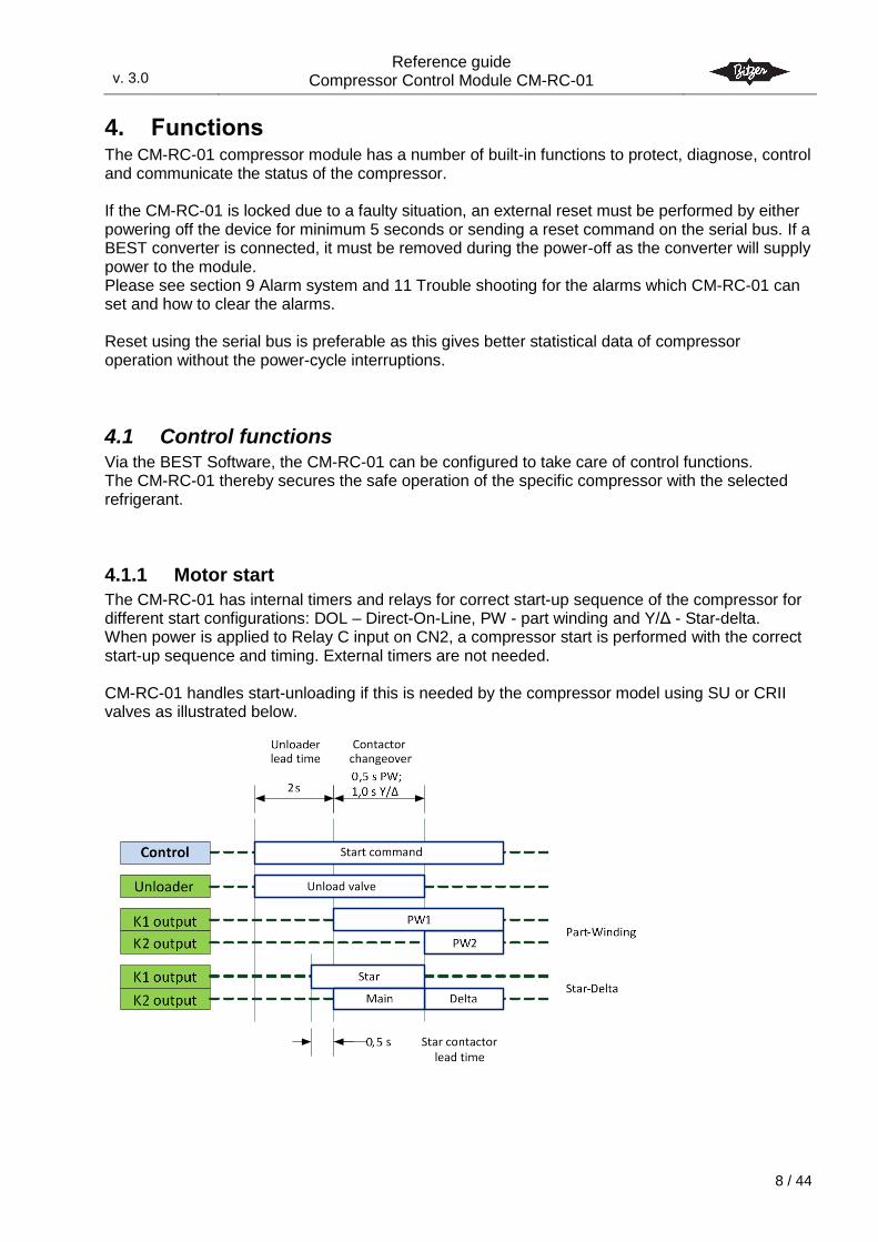
The CM-RC-01 has internal timers and relays for correct start-up sequence of the compressor for different start configurations: DOL – Direct-On-Line, PW - part winding and Y/Δ - Star-delta. When power is applied to Relay C input on CN2, a compressor start is performed with the correct start-up sequence and timing. External timers are not needed. CM-RC-01 handles start-unloading if this is needed by the compressor model using SU or CRII valves as illustrated below.
v. 3.0
Reference guide Compressor Control Module CM-RC-01
3.0
9 / 44
4.1.2 Oil heater
The oil heater ensures lubricity of the oil even after long standstill periods. It prevents increased refrigerant dilution in the oil and therefore a reduction of viscosity. The oil heater is switched on during standstill and switched off during compressor operation.
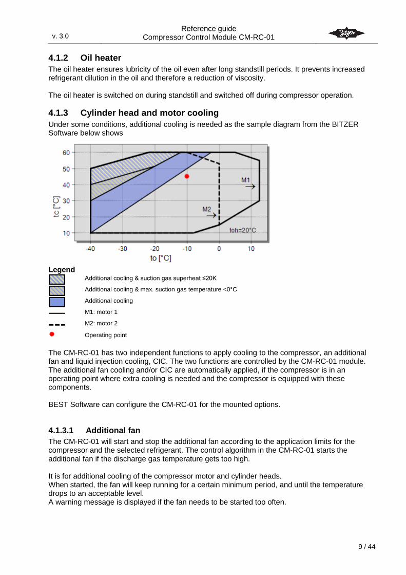
4.1.3 Cylinder head and motor cooling
Under some conditions, additional cooling is needed as the sample diagram from the BITZER Software below shows
Legend
Additional cooling & suction gas superheat ≤20K
Additional cooling & max. suction gas temperature <0°C
Additional cooling
M1: motor 1
M2: motor 2
Operating point
The CM-RC-01 has two independent functions to apply cooling to the compressor, an additional fan and liquid injection cooling, CIC. The two functions are controlled by the CM-RC-01 module. The additional fan cooling and/or CIC are automatically applied, if the compressor is in an operating point where extra cooling is needed and the compressor is equipped with these components. BEST Software can configure the CM-RC-01 for the mounted options.
4.1.3.1 Additional fan
The CM-RC-01 will start and stop the additional fan according to the application limits for the compressor and the selected refrigerant. The control algorithm in the CM-RC-01 starts the additional fan if the discharge gas temperature gets too high. It is for additional cooling of the compressor motor and cylinder heads. When started, the fan will keep running for a certain minimum period, and until the temperature drops to an acceptable level. A warning message is displayed if the fan needs to be started too often.
v. 3.0
Reference guide Compressor Control Module CM-RC-01
3.0
10 / 44
4.1.3.2 Liquid injection cooling (CIC)
CIC is a cooling system to reduce the discharge gas temperature. The control algorithm for the liquid injection cooling in the CM-RC-01 starts the CIC if the discharge gas temperature gets too high.
4.1.4 Capacity control
The CM-RC-01 can control the needed capacity of the compressor by controlling the CRII valves. The 0 – 10 V Cap. In input or the Modbus parameter Serial setpoint (see section 0 ) can be used to specify the needed capacity of the compressor. The compressor must be mounted with a CRII capacity regulation system. The CM-RC-01 will operate the CRII valve(s) to achieve the requested capacity with as little pressure fluctuations as possible. The capacity range is 10 % - 100 %. When liquid injection cooling (CIC) needs to run due to high discharge temperature, the capacity system will be forced to run with a certain minimum capacity, in order to avoid flooding of the compressor.
4.2 Monitoring and diagnosis
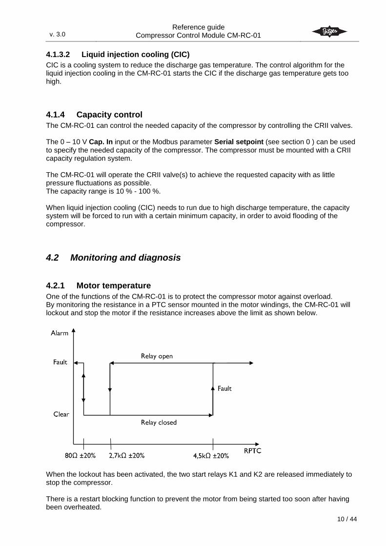
4.2.1 Motor temperature
One of the functions of the CM-RC-01 is to protect the compressor motor against overload. By monitoring the resistance in a PTC sensor mounted in the motor windings, the CM-RC-01 will lockout and stop the motor if the resistance increases above the limit as shown below.
When the lockout has been activated, the two start relays K1 and K2 are released immediately to stop the compressor. There is a restart blocking function to prevent the motor from being started too soon after having been overheated.
v. 3.0
Reference guide Compressor Control Module CM-RC-01
3.0
11 / 44
If the CM-RC-01 is locked, an external reset must be performed by either powering off the device for minimum 5 seconds or sending a reset command on the serial bus. When power is turned on to the CM-RC-01 module, the PTC resistance is measured:
If PTC resistance is below the reset limit 2,7 kΩ: No alarm: The relays are energized immediately (if no other faults are present)
If PTC resistance is between 2,7 kΩ and 4,5 kΩ: Alarm: The relays are first energized when below 2,7 kΩ (compressor motor has cooled down)
If PTC resistance is above 4,5 kΩ: Alarm lock: The relays are not energized and the module is locked
4.2.2 Discharge temperature
A temperature sensor is mounted on the discharge side of the compressor; the CM-RC-01 will open the relays and break the safety chain if the discharge temperature threshold is exceeded. The default thresholds for the selected reciprocating compressor are defined in the BEST software.
4.2.3 Oil supply
Depending on the compressor type, the oil supply monitor is configured for either oil level (OLC-D1) or oil pressure difference (DP-1) monitoring. Actual status is always accessible via Modbus. If an oil level fault is detected, the status is immediately updated via Modbus. However, the first 90 seconds after compressor start, the fault signal is not activated. If the oil level is still too low, the CM-RC-01 releases the fault relay and locks out immediately. The OLC-D1 module (24 V version) must be used for the oil level detection. A warning signal is set immediately if the compressor is running and the OLC input is open. If an oil pressure difference fault is detected, the status is immediately updated via Modbus. The first 90 seconds after compressor start, the fault signal is not activated. If the oil pressure difference is still too low, the CM-RC-01 releases the fault relay and locks out immediately. Both oil fault alarms must be externally reset by either powering off the device for minimum 5 seconds or sending a reset command on the serial bus.
4.2.4 High pressure handling
A high-pressure switch can be connected to the CN2 of the CM-RC-01. An alarm is set on CN2:Relay NC and on Modbus if the high-pressure switch opens.
4.2.5 Pressure limits (option)
In the BEST software a low pressure and a high pressure limits can be configured. If one of the limits are reached, the compressor is stopped and an alarm is issued.
v. 3.0
Reference guide Compressor Control Module CM-RC-01
3.0
12 / 44
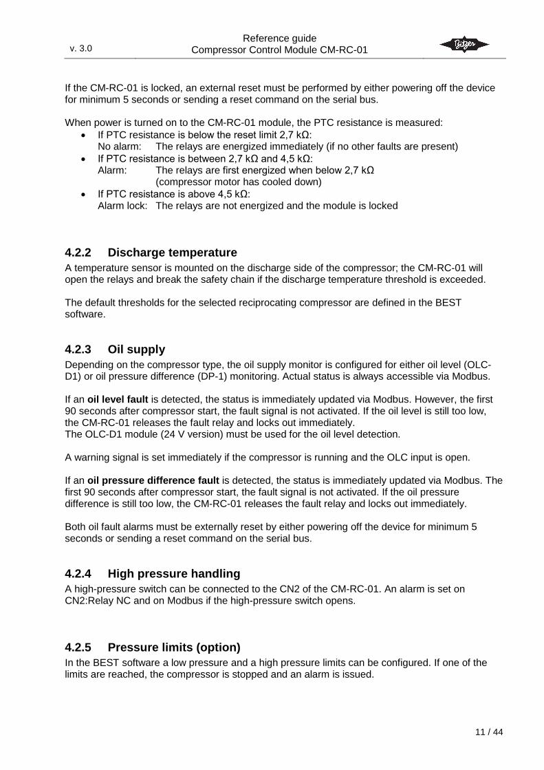
4.2.6 Application limits (option)
Optional pressure transducers are needed. The application limits function monitors if the operating conditions of the compressor is within the safe operation area limits – as shown in the BITZER Software when doing compressor calculations. The BITZER Software can be downloaded from BITZER’s homepage, www.BITZER.de. The operating point is determined by the saturated suction and discharge gas temperatures, which are calculated from the suction and discharge gas pressure based on the selected refrigerant. The figure below shows the multi-level monitoring of the application limits and behaviour when a limit is reached. Active warning, critical and faults are set inactive when the operating point again is within the reset-limit.
HP cut-out and LP cut-out are configured in the BEST Software.
Evaporating temperature to (SST) [°C]
Co
nd
ensi
ng
tem
per
atu
re t
c (S
DT)
[°C
]
HP cut-out
LP c
ut-
ou
t
Application limit
Warning reset
Warning limit
Critical limit (shut off after 30s)
Fault limit (Immediately shut-off)
High- and Low pressure cut-out
Active 120 s after compressor start
Fault limit, direct shut-off:
The compressor will stop immediately if this limit is reached!
Envelope status = 6 Fault Critical limit, shut-off after 30 s:
30s delay time to bring compressor back inside application limit else the compressor is stopped with a Fault alarm
Critical (30s period starts)
Envelope status = 5 Critical Warning limit:
Warning to system controller
No further actions
Envelope status = 4 Warning Warning reset
Automatic clear of warning
v. 3.0
Reference guide Compressor Control Module CM-RC-01
3.0
13 / 44
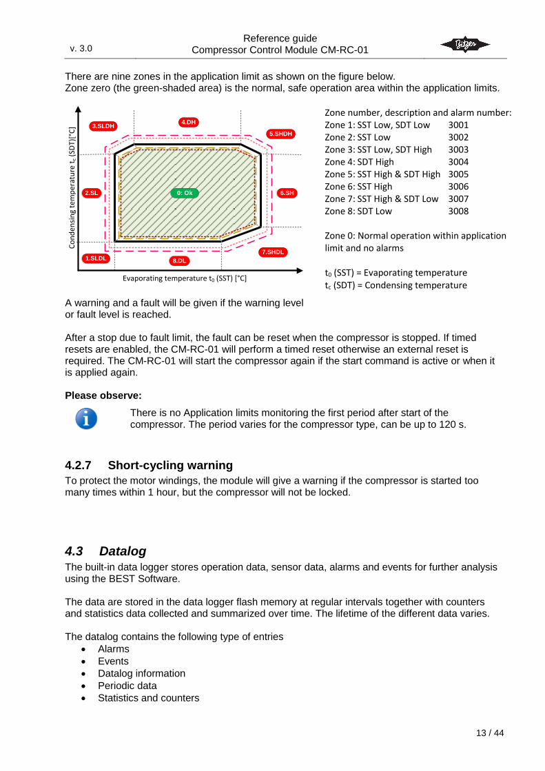
There are nine zones in the application limit as shown on the figure below. Zone zero (the green-shaded area) is the normal, safe operation area within the application limits.
A warning and a fault will be given if the warning level or fault level is reached. After a stop due to fault limit, the fault can be reset when the compressor is stopped. If timed resets are enabled, the CM-RC-01 will perform a timed reset otherwise an external reset is required. The CM-RC-01 will start the compressor again if the start command is active or when it is applied again. Please observe:
There is no Application limits monitoring the first period after start of the compressor. The period varies for the compressor type, can be up to 120 s.
4.2.7 Short-cycling warning
To protect the motor windings, the module will give a warning if the compressor is started too many times within 1 hour, but the compressor will not be locked.
4.3 Datalog The built-in data logger stores operation data, sensor data, alarms and events for further analysis using the BEST Software. The data are stored in the data logger flash memory at regular intervals together with counters and statistics data collected and summarized over time. The lifetime of the different data varies. The datalog contains the following type of entries
Alarms
Events
Datalog information
Periodic data
Statistics and counters
6.SH2.SL
1.SLDL
3.SLDH4.DH
5.SHDH
7.SHDL
8.DL
Evaporating temperature t0 (SST) [°C]
Co
nd
ensi
ng
tem
per
atu
re t
c (S
DT)
[°C
]
0: Ok
Zone number, description and alarm number: Zone 1: SST Low, SDT Low 3001 Zone 2: SST Low 3002 Zone 3: SST Low, SDT High 3003 Zone 4: SDT High 3004 Zone 5: SST High & SDT High 3005 Zone 6: SST High 3006 Zone 7: SST High & SDT Low 3007 Zone 8: SDT Low 3008 Zone 0: Normal operation within application limit and no alarms t0 (SST) = Evaporating temperature tc (SDT) = Condensing temperature
v. 3.0
Reference guide Compressor Control Module CM-RC-01
3.0
14 / 44
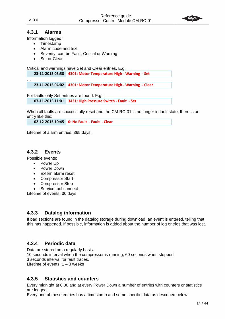
4.3.1 Alarms
Information logged:
Timestamp
Alarm code and text
Severity, can be Fault, Critical or Warning
Set or Clear Critical and warnings have Set and Clear entries. E.g.
23-11-2015 03:58 4301: Motor Temperature High - Warning - Set
…
23-11-2015 04:02 4301: Motor Temperature High - Warning - Clear
For faults only Set entries are found. E.g.:
07-11-2015 11:01 3431: High Pressure Switch - Fault - Set
When all faults are successfully reset and the CM-RC-01 is no longer in fault state, there is an entry like this:
02-12-2015 10:45 0: No Fault - Fault - Clear
Lifetime of alarm entries: 365 days.
4.3.2 Events
Possible events:
Power Up
Power Down
Extern alarm reset
Compressor Start
Compressor Stop
Service tool connect Lifetime of events: 30 days
4.3.3 Datalog information
If bad sections are found in the datalog storage during download, an event is entered, telling that this has happened. If possible, information is added about the number of log entries that was lost.
4.3.4 Periodic data
Data are stored on a regularly basis. 10 seconds interval when the compressor is running, 60 seconds when stopped. 3 seconds interval for fault traces. Lifetime of events: 1 – 3 weeks
4.3.5 Statistics and counters
Every midnight at 0:00 and at every Power Down a number of entries with counters or statistics are logged. Every one of these entries has a timestamp and some specific data as described below.
v. 3.0
Reference guide Compressor Control Module CM-RC-01
3.0
15 / 44
4.3.6 Accumulated operation counters
All accumulated since first power up
No of PowerUps
No of Motor Starts
Operating Hours
Motor Operating Hours Lifetime: 365 days
4.3.7 Capacity load
Device Operating Time – number of minutes, that is basis for the next values
Cap.Load 0 – percentage of the time, where the compressor was at standstill
Cap.Load 11-20 – percentage of the time, where the compressor had a load in the range 11-20 %
…
Cap.Load 91-100 – percentage of the time, where the compressor had a load in the range 91-100 %
Lifetime: 365 days
4.3.8 Daily counters
Device Power Ups
Compressor Starts
Number of Faults
Number of Criticals
Number of Warnings
Device Operating Time
Compressor Runtime
Fault Runtime
Critical Runtime
Warning Runtime
Capacity Usage Rate Lifetime: 365 days
4.3.9 Runtime statistic
Number of runs 0-4 min
Number of runs 5-9 min
Number of runs 10-19 min
Number of runs 20-29 min
Number of runs 30-59 min
Number of runs 60-119 min
Number of runs 120-299 min
Number of runs >300 min Lifetime: 365 days
4.3.10 Compressor start statistic
starts/h
2-4 starts/h
5-9 starts/h
v. 3.0
Reference guide Compressor Control Module CM-RC-01
3.0
16 / 44
10-14 starts/h
15-19 starts/h
>20 starts/h Lifetime: 365 days
4.4 BEST software The BEST Software is used for live monitoring of operation conditions, download of datalogs and configuration of the CM-RC-01. The BEST Software can be downloaded from the BITZER homepage, www.bitzer.de.
4.5 Communication Detailed status information and communication with the system controller is done via the Modbus (RTU) interface. Please see the detailed description in section 10 Programming and monitoring. A Bluetooth module will be added soon.
v. 3.0
Reference guide Compressor Control Module CM-RC-01
3.0
17 / 44
5. Control of the CM-RC-01 Control commands and setpoint can be given to the CM-RC-01 via different interfaces Digital inputs: Start/stop Analogue input: Setpoint Serial control: Commands and setpoint The commands from the different interfaces are merged and the resulting “Control Word” can be read via the serial Interface. The capacity is limited between 10 % and 100 % even if the sum of the setpoints may be below 100 % or above 100 %. The serial protocol is Modbus (RTU). Modbus can be connected for example for monitoring only but still using the digital and analogue inputs for control of the CM-RC-01. Most common is to monitor and control the CM-RC-01 via the Modbus interface. The serial control is inactive by default. Please see section 5.2 Enable serial control.
5.1 Commands and setpoint The basic operation of the CM-RC-01 is controlled by
Commands: Start and stop
Setpoint – analogue or serial control
Setting of serial control parameters o "Serial Control Source"; default is none: 0 – 10V input
See parameter in section 10.3.7 Configuration – application o Setting of the refrigerant (if not done via the BEST Software)
Commands and setpoint can be given via the digital and analogue inputs or by combining the digital and analogue inputs with values from the serial interface. See later in this section.
5.1.1 Command Start
The Start command becomes active when a start signal is given via digital input or serial control. If the compressor is started too many times per hour, the CM-RC-01 will give a waning but the compressor will be allowed to start The speed of the motor will normally match the setpoint. Details are described below. When the motor is running and the start condition is removed (Start is set to inactive), the compressor is stopped.
5.1.2 Setpoint – and speed changes
The setpoint is a value in the range -100 % to +100 %. There is no ramping of a capacity change request. The setpoint from the analogue input and the serial control are added. E.g. the analogue signal could be an offset and the serial control could be the fine tuning. Analogue control: Apply a 0 – 10V speed signal (0 – 100%) to the CN13 Cap. Input. Serial control: Set the capacity request in parameter Serial Setpoint (-100 % – +100%) Please see section 10.3.1 Control – application for the parameter to use for the setpoint.
v. 3.0
Reference guide Compressor Control Module CM-RC-01
3.0
18 / 44
5.2 Enable serial control The serial control is inactive by default. To enable the serial control set the parameter to 1 (COM1 Modbus). To disable serial control: Set parameter “Serial Control Source” to 0 (= None).
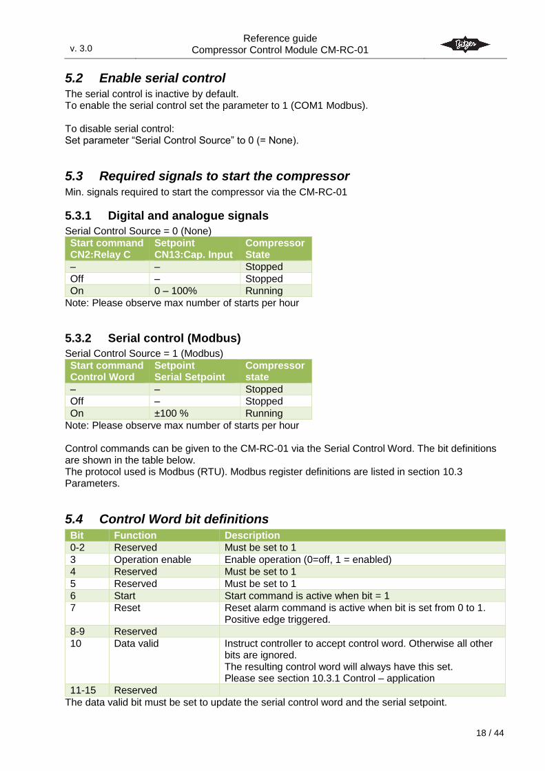
5.3 Required signals to start the compressor Min. signals required to start the compressor via the CM-RC-01
5.3.1 Digital and analogue signals
Serial Control Source = 0 (None)
Start command CN2:Relay C
Setpoint CN13:Cap. Input
Compressor State
– – Stopped
Off – Stopped
On 0 – 100% Running
Note: Please observe max number of starts per hour
5.3.2 Serial control (Modbus)
Serial Control Source = 1 (Modbus)
Start command Control Word
Setpoint Serial Setpoint
Compressor state
– – Stopped
Off – Stopped
On ±100 % Running
Note: Please observe max number of starts per hour Control commands can be given to the CM-RC-01 via the Serial Control Word. The bit definitions are shown in the table below. The protocol used is Modbus (RTU). Modbus register definitions are listed in section 10.3 Parameters.
5.4 Control Word bit definitions
Bit Function Description
0-2 Reserved Must be set to 1
3 Operation enable Enable operation (0=off, 1 = enabled)
4 Reserved Must be set to 1
5 Reserved Must be set to 1
6 Start Start command is active when bit = 1
7 Reset Reset alarm command is active when bit is set from 0 to 1. Positive edge triggered.
8-9 Reserved
10 Data valid Instruct controller to accept control word. Otherwise all other bits are ignored. The resulting control word will always have this set. Please see section 10.3.1 Control – application
11-15 Reserved
The data valid bit must be set to update the serial control word and the serial setpoint.
v. 3.0
Reference guide Compressor Control Module CM-RC-01
3.0
19 / 44
The Control Word is the active control word. Use the Serial Control Word for configuration of the CM-RC-01.
5.4.1 Data valid bit
When the data valid bit is set to “1” setpoint and commands are accepted from the serial control interface. When the data valid bit is set to “0” all other bits in the control word and the setpoint are ignored. This means that if the start command was active just before the data valid bit is set to “0” the command remains active until the data valid bit is set to “1” and the start bit is set to “0”. Please note that the Serial Control Source must be 1 (Modbus).
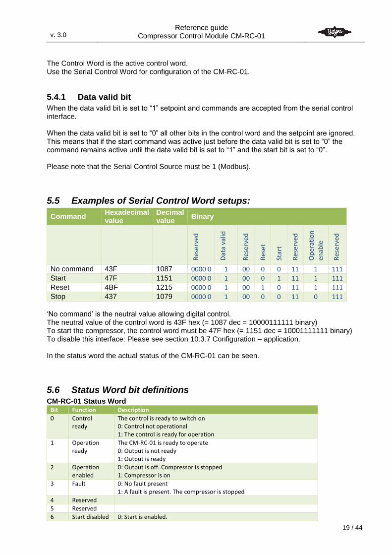
5.5 Examples of Serial Control Word setups:
Command Hexadecimal value
Decimal value
Binary
Res
erv
ed
Dat
a va
lid
Res
erv
ed
Res
et
Star
t
Res
erv
ed
Op
erat
ion
enab
le
Res
erv
ed
No command 43F 1087 0000 0 1 00 0 0 11 1 111
Start 47F 1151 0000 0 1 00 0 1 11 1 111
Reset 4BF 1215 0000 0 1 00 1 0 11 1 111
Stop 437 1079 0000 0 1 00 0 0 11 0 111
‘No command’ is the neutral value allowing digital control. The neutral value of the control word is 43F hex (= 1087 dec = 10000111111 binary) To start the compressor, the control word must be 47F hex (= 1151 dec = 10001111111 binary) To disable this interface: Please see section 10.3.7 Configuration – application. In the status word the actual status of the CM-RC-01 can be seen.
5.6 Status Word bit definitions CM-RC-01 Status Word
Bit Function Description
0 Control ready
The control is ready to switch on 0: Control not operational 1: The control is ready for operation
1 Operation ready
The CM-RC-01 is ready to operate 0: Output is not ready 1: Output is ready
2 Operation enabled
0: Output is off. Compressor is stopped 1: Compressor is on
3 Fault 0: No fault present 1: A fault is present. The compressor is stopped
4 Reserved
5 Reserved
6 Start disabled 0: Start is enabled.
v. 3.0
Reference guide Compressor Control Module CM-RC-01
3.0
20 / 44
5.7 Setting the serial setpoint The serial setpoint is set via the Modbus holding register 111:
Modbus
type & addr Name
Possible
values Default Description
HR 111 Serial Setpoint (Control.SerSetpoint)
-100.00 % - 100.00 %
scale 100
sint16
0 % Capacity setpoint written by serial communication
5.8 Serial Control Timeout Function If the communication is interrupted, the CM-RC-01 can be configured for different reactions to this interrupt
None – continue operation
Stop – stop operation
Fault – Stop and signal fault alarm Default function is to let the CM-RC-01 continue without any changes (None). The timeout for activation and the different reactions of the Serial Control Timeout Function can be adjusted. Every update of the Serial control word resets the timeout function. Default timeout is 60 seconds. Please see section 10.3.7 Configuration – application for further information.
1: Start is disabled
7 Warning 0: No warning present 1: A warning is present. The CM-RC-01 continues operation, but attention may be required
8 On reference 0: The compressor is ramping or not running 1: The compressor is operating at setpoint
9 Reserved
10 Reserved
11 Running 0: Compressor is not running 1: The compressor is running
12 Start active 0: Start command is not given OR start is prohibited 1: Start command is given (e.g. start signal is given, setpoint > 0 %) and Operation is enabled
13 Critical 0: No critical present 1: A critical is present. The CM-RC-01 is close at its limits and may soon stop the compressor
14-15
Reserved
v. 3.0
Reference guide Compressor Control Module CM-RC-01
3.0
21 / 44
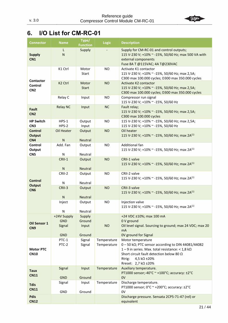
6. I/O List for CM-RC-01
Connector Name Type/
Function Logic Description
Supply CN1
L N
Supply - Supply for CM-RC-01 and control outputs; 115 V-230 V; +10% ~ -15%, 50/60 Hz; max 500 VA with external components Fuse 8A T @115VAC; 4A T@230VAC
Contactor Control CN2
K1 Ctrl Motor Start
NO Activate K1 contactor 115 V-230 V; +10% ~ -15%, 50/60 Hz; max 2,5A; C300 max 100.000 cycles; D300 max 350.000 cycles
K2 Ctrl Motor Start
NO Activate K2 contactor 115 V-230 V; +10% ~ -15%, 50/60 Hz; max 2,5A; C300 max 100.000 cycles; D300 max 350.000 cycles
Relay C Input NO Compressor run signal 115 V-230 V; +10% ~ -15%, 50/60 Hz
Fault CN2
Relay NC Input NC Fault relay; 115 V-230 V; +10% ~ -15%, 50/60 Hz; max 2,5A; C300 max 100.000 cycles
HP Switch CN3
HPS-1 HPS-2
Output Input
NO
115 V-230 V; +10% ~ -15%, 50/60 Hz; max 2,5A; 115 V-230 V; +10% ~ -15%, 50/60 Hz
Control Output CN4
Oil Heater
N
Output
Neutral
NO Oil heater 115 V-230 V; +10% ~ -15%, 50/60 Hz; max 2A(1)
Control Output CN5
Add. Fan
N
Output
Neutral
NO Additional fan 115 V-230 V; +10% ~ -15%, 50/60 Hz; max 2A(1)
Control Output CN6
CRII-1
N
Output
Neutral
NO
CRII-1 valve 115 V-230 V; +10% ~ -15%, 50/60 Hz; max 2A(1)
CRII-2
N
Output
Neutral
NO
CRII-2 valve 115 V-230 V; +10% ~ -15%, 50/60 Hz; max 2A(1)
CRII-3
N
Output
Neutral
NO
CRII-3 valve 115 V-230 V; +10% ~ -15%, 50/60 Hz; max 2A(1)
Inject
N
Output
Neutral
NO Injection valve 115 V-230 V; +10% ~ -15%, 50/60 Hz; max 2A(1)
Oil Sensor 1 CN9
+24V Supply GND
Signal
GND
Supply Ground
Input
Ground
NO
+24 VDC ±10%; max 100 mA 0 V ground Oil level signal. Sourcing to ground; max 24 VDC; max 20 mA 0V ground for Signal
Motor PTC CN10
PTC-1 PTC-2
Signal Signal
Temperature Temperature
Motor temperature 0 – 50 kΩ; PTC sensor according to DIN 44081/44082 1 – 9 in series. Max. total resistance: < 1,8 kΩ Short circuit fault detection below 80 Ω Rtrig: 4,5 kΩ ±20% Rreset: 2,7 kΩ ±20%
Taux CN11 Tdis CN11
Signal
GND
Input
Ground
Temperature Auxiliary temperature. PT1000 sensor;-40°C ~ +100°C; accuracy: ±2°C 0V
Signal
GND
Input
Ground
Temperature Discharge temperature. PT1000 sensor; 0°C ~ +200°C; accuracy: ±2°C 0V
Pdis CN12
Discharge pressure. Sensata 2CP5-71-47 (rel) or equivalent
v. 3.0
Reference guide Compressor Control Module CM-RC-01
3.0
22 / 44
Connector Name Type/
Function Logic Description
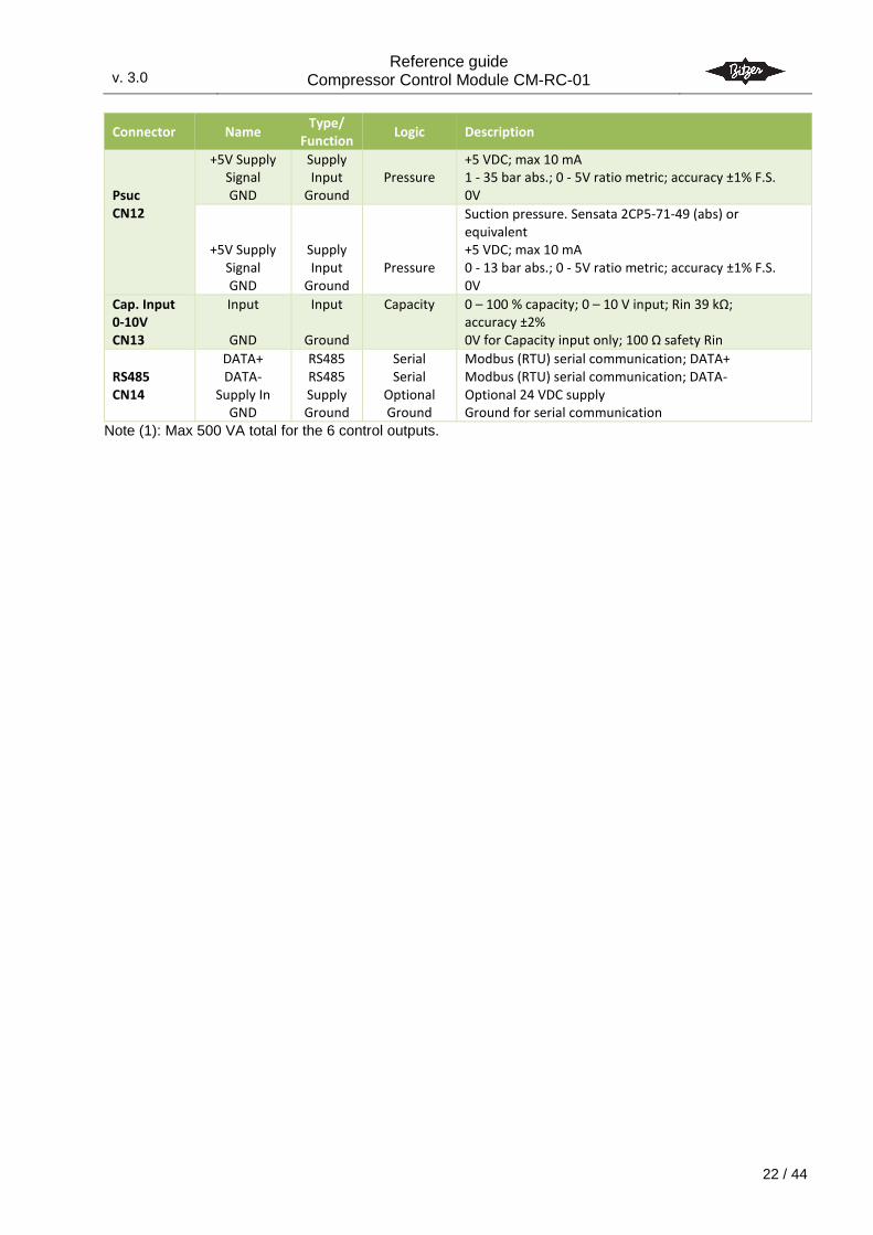
Psuc CN12
+5V Supply Signal GND
Supply Input
Ground
Pressure
+5 VDC; max 10 mA 1 - 35 bar abs.; 0 - 5V ratio metric; accuracy ±1% F.S. 0V
+5V Supply Signal GND
Supply Input
Ground
Pressure
Suction pressure. Sensata 2CP5-71-49 (abs) or equivalent +5 VDC; max 10 mA 0 - 13 bar abs.; 0 - 5V ratio metric; accuracy ±1% F.S. 0V
Cap. Input 0-10V CN13
Input
GND
Input
Ground
Capacity 0 – 100 % capacity; 0 – 10 V input; Rin 39 kΩ; accuracy ±2% 0V for Capacity input only; 100 Ω safety Rin
RS485 CN14
DATA+ DATA-
Supply In GND
RS485 RS485 Supply Ground
Serial Serial
Optional Ground
Modbus (RTU) serial communication; DATA+ Modbus (RTU) serial communication; DATA- Optional 24 VDC supply Ground for serial communication
Note (1): Max 500 VA total for the 6 control outputs.
v. 3.0
Reference guide Compressor Control Module CM-RC-01
3.0
23 / 44
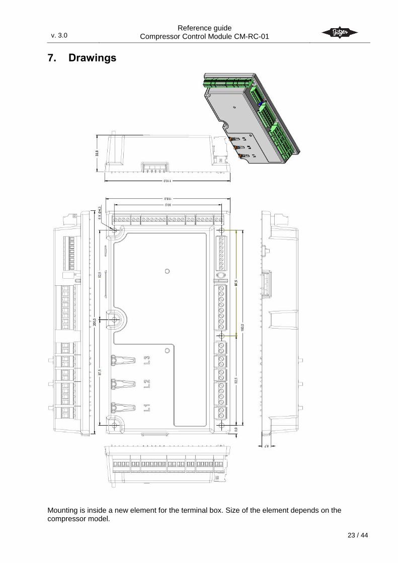
7. Drawings
Mounting is inside a new element for the terminal box. Size of the element depends on the compressor model.
v. 3.0
Reference guide Compressor Control Module CM-RC-01
3.0
24 / 44
8. Standards The product is manufactured according to the following standards.
RoHS 2002/95/EC
Low voltage 206/95/EC
61010-1 Safety requirement for electrical equipment for measurement and control
EMC 2004/108/EC
61000-6-x Generic EMC The following standards have been used
EN 61010-1 Safety requirement for electrical equipment for measurement and control
EN 61000-6-2 Immunity standard for industrial environments
EN 61000-6-3 Emission standard for residential, commercial and light-industrial environments
v. 3.0
Reference guide Compressor Control Module CM-RC-01
3.0
25 / 44
9. Alarm system Both warning, alarm and locked states are visible via LEDs and via the serial communication bus. Via the serial communication bus, more information regarding an alarm is available as listed in the table below.
9.1 Alarm severity types There are the following alarm severity types: Fault:
If a fault-level alarm condition is detected, the CM-RC-01 will open the relays for the motor contacts and stop the compressor motor.
A fault is logged in the fault log. Critical:
If a critical-level alarm condition is detected, operation may continue but for a limited time or with reduced performance.
Warning:
A warning is signalled when a condition occurs which may require attention but is not severe enough to stop operation of the compressor. The compressor keeps running.
Warnings, Criticals and Faults can be active at the same time as they may have separate alarm and reset limits.
9.2 Fault reset types Below are listed the different methods to reset faults. A reset will dismiss faults only if the fault condition has disappeared. An external-reset resets both externally alarms and timed resettable alarms; a timed reset however, can only reset timed resettable alarms. Restart: Cleared by a power cycle of the CM-RC-01 Extern reset: The fault is cleared if the fault condition has disappeared when the reset command
is received Timed reset: Timed reset is an automatic, repetitive, timed reset.
Timed resets will be issued with an interval of ”Timed Reset Timeout” time as long as a timed resettable fault is present.
Auto: Automatic reset of faults when the fault condition disappears.
v. 3.0
Reference guide Compressor Control Module CM-RC-01
3.0
26 / 44
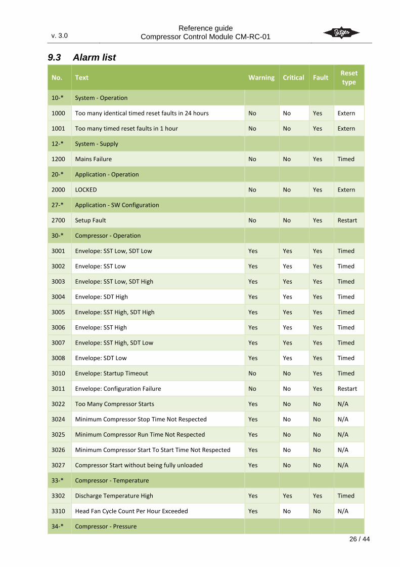
9.3 Alarm list
No. Text Warning Critical Fault Reset type
10-* System - Operation
1000 Too many identical timed reset faults in 24 hours No No Yes Extern
1001 Too many timed reset faults in 1 hour No No Yes Extern
12-* System - Supply
1200 Mains Failure No No Yes Timed
20-* Application - Operation
2000 LOCKED No No Yes Extern
27-* Application - SW Configuration
2700 Setup Fault No No Yes Restart
30-* Compressor - Operation
3001 Envelope: SST Low, SDT Low Yes Yes Yes Timed
3002 Envelope: SST Low Yes Yes Yes Timed
3003 Envelope: SST Low, SDT High Yes Yes Yes Timed
3004 Envelope: SDT High Yes Yes Yes Timed
3005 Envelope: SST High, SDT High Yes Yes Yes Timed
3006 Envelope: SST High Yes Yes Yes Timed
3007 Envelope: SST High, SDT Low Yes Yes Yes Timed
3008 Envelope: SDT Low Yes Yes Yes Timed
3010 Envelope: Startup Timeout No No Yes Timed
3011 Envelope: Configuration Failure No No Yes Restart
3022 Too Many Compressor Starts Yes No No N/A
3024 Minimum Compressor Stop Time Not Respected Yes No No N/A
3025 Minimum Compressor Run Time Not Respected Yes No No N/A
3026 Minimum Compressor Start To Start Time Not Respected Yes No No N/A
3027 Compressor Start without being fully unloaded Yes No No N/A
33-* Compressor - Temperature
3302 Discharge Temperature High Yes Yes Yes Timed
3310 Head Fan Cycle Count Per Hour Exceeded Yes No No N/A
34-* Compressor - Pressure
v. 3.0
Reference guide Compressor Control Module CM-RC-01
3.0
27 / 44
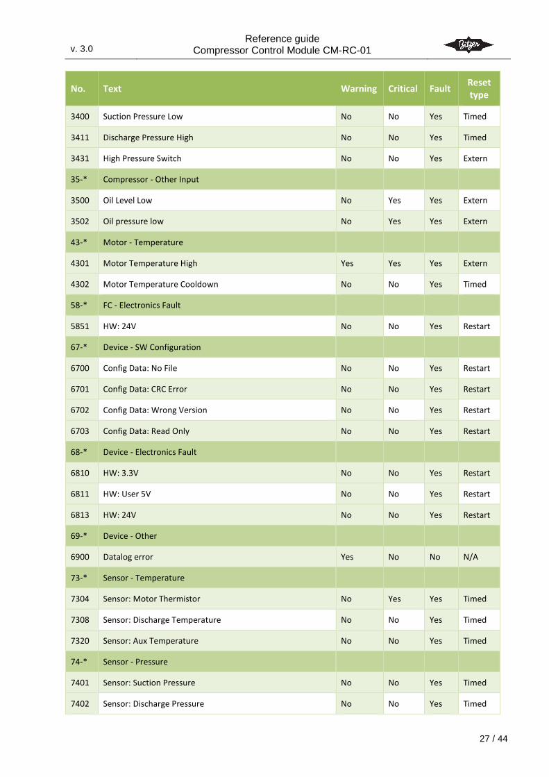
No. Text Warning Critical Fault Reset type
3400 Suction Pressure Low No No Yes Timed
3411 Discharge Pressure High No No Yes Timed
3431 High Pressure Switch No No Yes Extern
35-* Compressor - Other Input
3500 Oil Level Low No Yes Yes Extern
3502 Oil pressure low No Yes Yes Extern
43-* Motor - Temperature
4301 Motor Temperature High Yes Yes Yes Extern
4302 Motor Temperature Cooldown No No Yes Timed
58-* FC - Electronics Fault
5851 HW: 24V No No Yes Restart
67-* Device - SW Configuration
6700 Config Data: No File No No Yes Restart
6701 Config Data: CRC Error No No Yes Restart
6702 Config Data: Wrong Version No No Yes Restart
6703 Config Data: Read Only No No Yes Restart
68-* Device - Electronics Fault
6810 HW: 3.3V No No Yes Restart
6811 HW: User 5V No No Yes Restart
6813 HW: 24V No No Yes Restart
69-* Device - Other
6900 Datalog error Yes No No N/A
73-* Sensor - Temperature
7304 Sensor: Motor Thermistor No Yes Yes Timed
7308 Sensor: Discharge Temperature No No Yes Timed
7320 Sensor: Aux Temperature No No Yes Timed
74-* Sensor - Pressure
7401 Sensor: Suction Pressure No No Yes Timed
7402 Sensor: Discharge Pressure No No Yes Timed
v. 3.0
Reference guide Compressor Control Module CM-RC-01
3.0
28 / 44
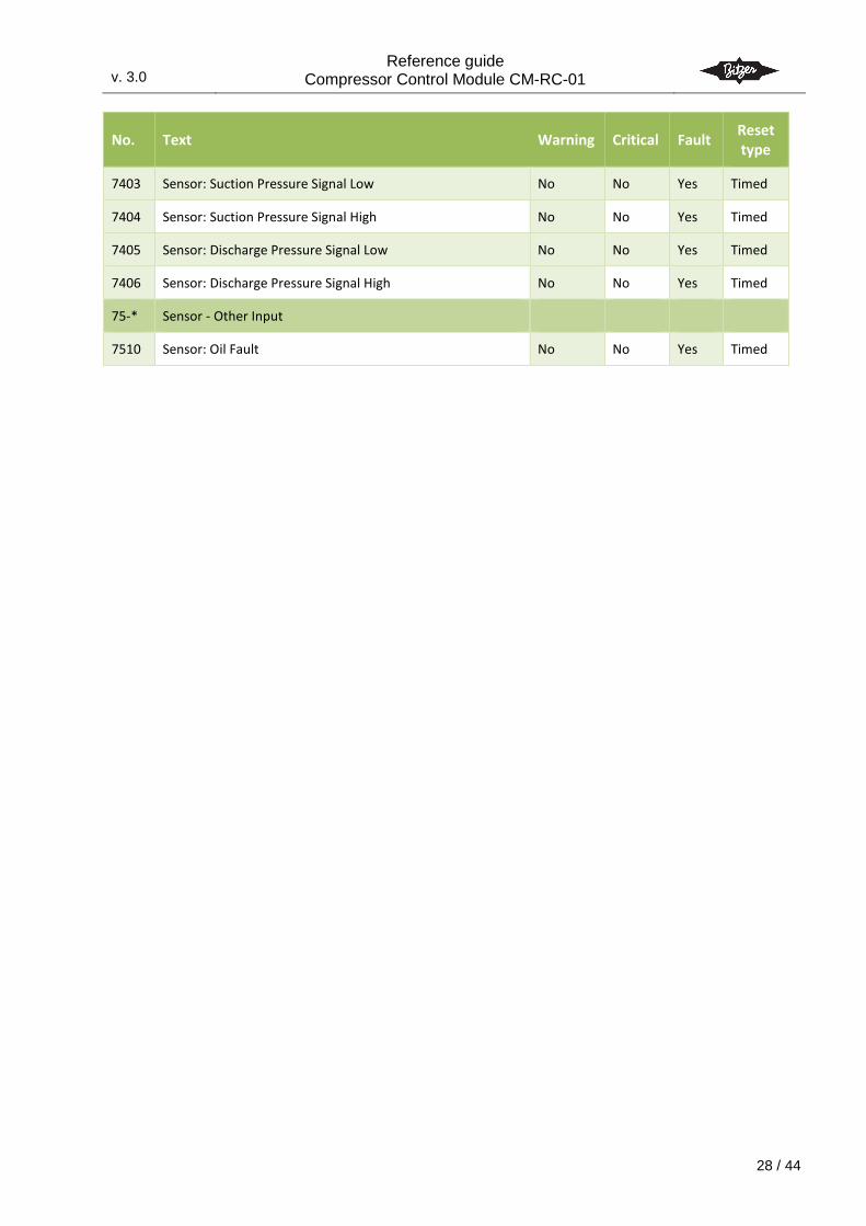
No. Text Warning Critical Fault Reset type
7403 Sensor: Suction Pressure Signal Low No No Yes Timed
7404 Sensor: Suction Pressure Signal High No No Yes Timed
7405 Sensor: Discharge Pressure Signal Low No No Yes Timed
7406 Sensor: Discharge Pressure Signal High No No Yes Timed
75-* Sensor - Other Input
7510 Sensor: Oil Fault No No Yes Timed
v. 3.0
Reference guide Compressor Control Module CM-RC-01
3.0
29 / 44
10. Programming and monitoring
10.1 Introduction For monitoring and controlling the CM-RC-01, there is a built-in Modbus (RTU) interface.
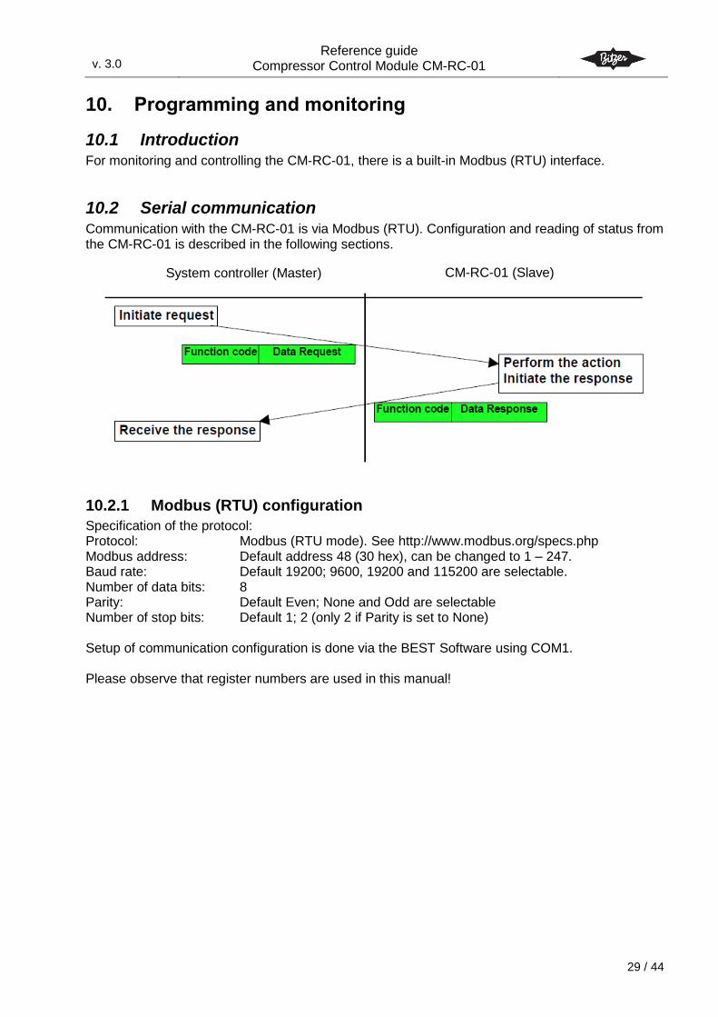
10.2 Serial communication Communication with the CM-RC-01 is via Modbus (RTU). Configuration and reading of status from the CM-RC-01 is described in the following sections.
10.2.1 Modbus (RTU) configuration
Specification of the protocol: Protocol: Modbus (RTU mode). See http://www.modbus.org/specs.php Modbus address: Default address 48 (30 hex), can be changed to 1 – 247. Baud rate: Default 19200; 9600, 19200 and 115200 are selectable. Number of data bits: 8 Parity: Default Even; None and Odd are selectable Number of stop bits: Default 1; 2 (only 2 if Parity is set to None) Setup of communication configuration is done via the BEST Software using COM1. Please observe that register numbers are used in this manual!
CM-RC-01 (Slave) System controller (Master)
v. 3.0
Reference guide Compressor Control Module CM-RC-01
3.0
30 / 44
10.2.2 Data values, scaling and data types
Following is a description of used scaling and data types. Scale 1, 10 and 100 refers to where the decimal point is implied, as a decimal value cannot be transmitted via Modbus. Scale 1: The value is the exact value Scale 10: To transmit a value it must be multiplied by 10; i.e. 12.3 -> 123 A received value must be divided by 10; i.e. 123 -> 12.3 Scale 100: To transmit a value it must be multiplied by 100; i.e. 1.23 -> 123 A received value must be divided by 100; i.e. 123 -> 1.23 W/R column: Read/write field. R = read (input) register; W = write (holding) register U8: unsigned 8-bit integer S8: signed 8-bit integer U16: unsigned 16-bit integer S16: signed 16-bit integer U32: unsigned 32-bit integer S32: signed 32-bit integer Ch16: 8 bit ASCII character text string. Null terminated if not max length.
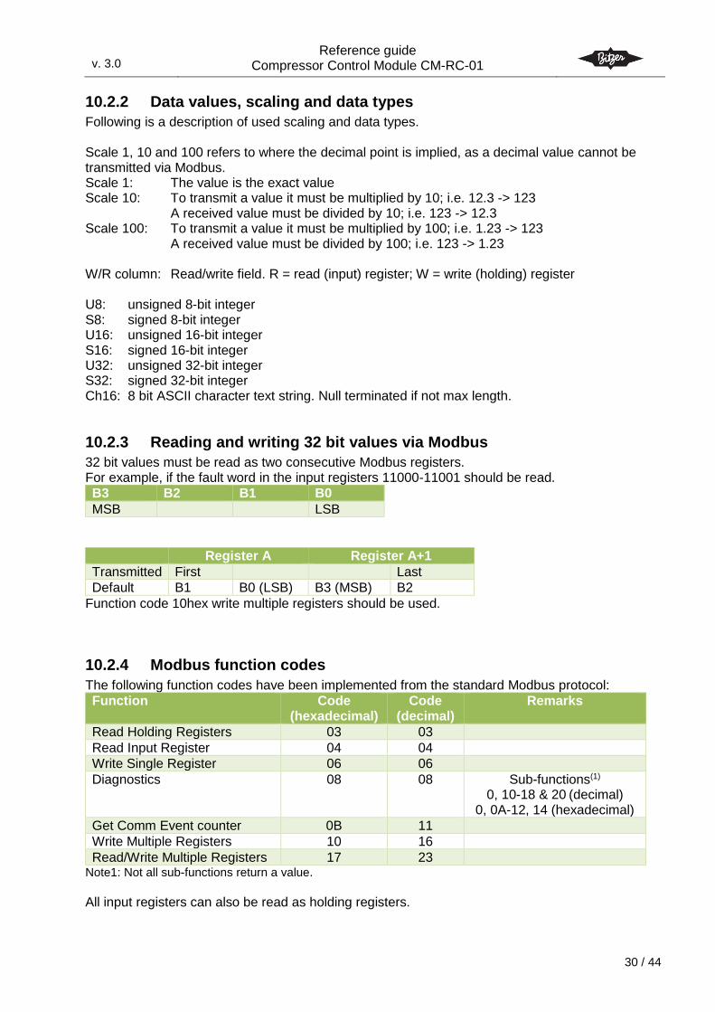
10.2.3 Reading and writing 32 bit values via Modbus
32 bit values must be read as two consecutive Modbus registers. For example, if the fault word in the input registers 11000-11001 should be read.
B3 B2 B1 B0
MSB LSB
Register A Register A+1
Transmitted First Last
Default B1 B0 (LSB) B3 (MSB) B2
Function code 10hex write multiple registers should be used.
10.2.4 Modbus function codes
The following function codes have been implemented from the standard Modbus protocol:
Function Code (hexadecimal)
Code (decimal)
Remarks
Read Holding Registers 03 03
Read Input Register 04 04
Write Single Register 06 06
Diagnostics 08 08 Sub-functions(1)
0, 10-18 & 20 (decimal) 0, 0A-12, 14 (hexadecimal)
Get Comm Event counter 0B 11
Write Multiple Registers 10 16
Read/Write Multiple Registers 17 23 Note1: Not all sub-functions return a value.
All input registers can also be read as holding registers.
v. 3.0
Reference guide Compressor Control Module CM-RC-01
3.0
31 / 44
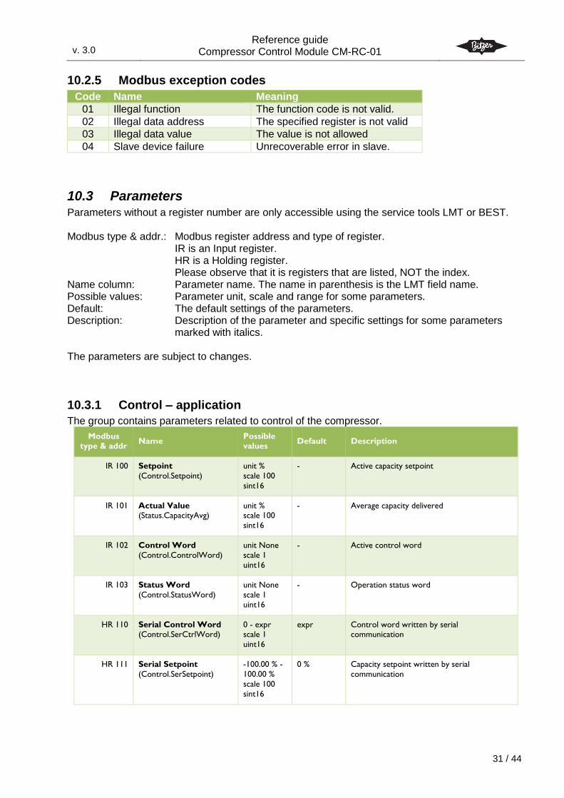
10.2.5 Modbus exception codes
Code Name Meaning
01 Illegal function The function code is not valid.
02 Illegal data address The specified register is not valid
03 Illegal data value The value is not allowed
04 Slave device failure Unrecoverable error in slave.
10.3 Parameters Parameters without a register number are only accessible using the service tools LMT or BEST. Modbus type & addr.: Modbus register address and type of register.
IR is an Input register. HR is a Holding register. Please observe that it is registers that are listed, NOT the index.
Name column: Parameter name. The name in parenthesis is the LMT field name. Possible values: Parameter unit, scale and range for some parameters. Default: The default settings of the parameters. Description: Description of the parameter and specific settings for some parameters
marked with italics. The parameters are subject to changes.
10.3.1 Control – application
The group contains parameters related to control of the compressor.
Modbus type & addr
Name Possible values
Default Description
IR 100 Setpoint
(Control.Setpoint)
unit %
scale 100
sint16
- Active capacity setpoint
IR 101 Actual Value (Status.CapacityAvg)
unit % scale 100
sint16
- Average capacity delivered
IR 102 Control Word
(Control.ControlWord)
unit None
scale 1
uint16
- Active control word
IR 103 Status Word
(Control.StatusWord)
unit None
scale 1
uint16
- Operation status word
HR 110 Serial Control Word (Control.SerCtrlWord)
0 - expr scale 1
uint16
expr Control word written by serial communication
HR 111 Serial Setpoint
(Control.SerSetpoint)
-100.00 % -
100.00 %
scale 100
sint16
0 % Capacity setpoint written by serial
communication
v. 3.0
Reference guide Compressor Control Module CM-RC-01
3.0
32 / 44
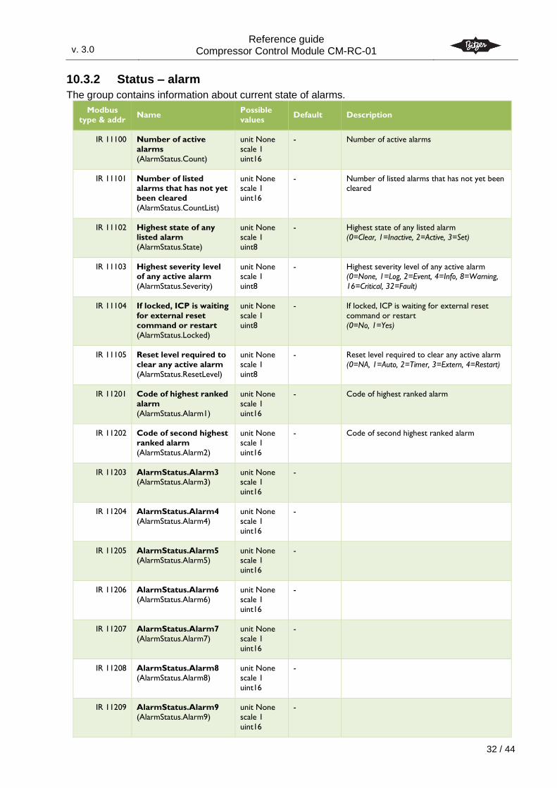
10.3.2 Status – alarm
The group contains information about current state of alarms.
Modbus
type & addr Name
Possible
values Default Description
IR 11100 Number of active
alarms
(AlarmStatus.Count)
unit None
scale 1
uint16
- Number of active alarms
IR 11101 Number of listed alarms that has not yet
been cleared
(AlarmStatus.CountList)
unit None scale 1
uint16
- Number of listed alarms that has not yet been cleared
IR 11102 Highest state of any
listed alarm
(AlarmStatus.State)
unit None
scale 1
uint8
- Highest state of any listed alarm
(0=Clear, 1=Inactive, 2=Active, 3=Set)
IR 11103 Highest severity level of any active alarm
(AlarmStatus.Severity)
unit None scale 1
uint8
- Highest severity level of any active alarm (0=None, 1=Log, 2=Event, 4=Info, 8=Warning,
16=Critical, 32=Fault)
IR 11104 If locked, ICP is waiting
for external reset
command or restart
(AlarmStatus.Locked)
unit None
scale 1
uint8
- If locked, ICP is waiting for external reset
command or restart
(0=No, 1=Yes)
IR 11105 Reset level required to
clear any active alarm
(AlarmStatus.ResetLevel)
unit None
scale 1
uint8
- Reset level required to clear any active alarm
(0=NA, 1=Auto, 2=Timer, 3=Extern, 4=Restart)
IR 11201 Code of highest ranked
alarm
(AlarmStatus.Alarm1)
unit None
scale 1
uint16
- Code of highest ranked alarm
IR 11202 Code of second highest
ranked alarm
(AlarmStatus.Alarm2)
unit None
scale 1
uint16
- Code of second highest ranked alarm
IR 11203 AlarmStatus.Alarm3 (AlarmStatus.Alarm3)
unit None scale 1
uint16
-
IR 11204 AlarmStatus.Alarm4
(AlarmStatus.Alarm4)
unit None
scale 1
uint16
-
IR 11205 AlarmStatus.Alarm5 (AlarmStatus.Alarm5)
unit None scale 1
uint16
-
IR 11206 AlarmStatus.Alarm6
(AlarmStatus.Alarm6)
unit None
scale 1
uint16
-
IR 11207 AlarmStatus.Alarm7
(AlarmStatus.Alarm7)
unit None
scale 1
uint16
-
IR 11208 AlarmStatus.Alarm8
(AlarmStatus.Alarm8)
unit None
scale 1
uint16
-
IR 11209 AlarmStatus.Alarm9
(AlarmStatus.Alarm9)
unit None
scale 1
uint16
-
v. 3.0
Reference guide Compressor Control Module CM-RC-01
3.0
33 / 44
Modbus
type & addr Name
Possible
values Default Description
IR 11210 AlarmStatus.Alarm10
(AlarmStatus.Alarm10)
unit None
scale 1
uint16
-
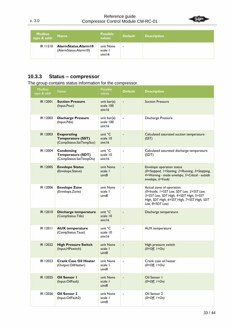
10.3.3 Status – compressor
The group contains status information for the compressor.
Modbus type & addr
Name Possible values
Default Description
IR 12001 Suction Pressure
(Input.Psuc)
unit bar(a)
scale 100
sint16
- Suction Pressure
IR 12002 Discharge Pressure (Input.Pdis)
unit bar(a) scale 100
sint16
- Discharge Pressure
IR 12003 Evaporating
Temperature (SST)
(CompStatus.SatTempSuc)
unit °C
scale 10
sint16
- Calculated saturated suction temperature
(SST)
IR 12004 Condensing Temperature (SDT)
(CompStatus.SatTempDis)
unit °C scale 10
sint16
- Calculated saturated discharge temperature (SDT)
IR 12005 Envelope Status
(Envelope.Status)
unit None
scale 1
uint8
- Envelope operation status
(0=Stopped, 1=Starting, 2=Running, 3=Stopping,
4=Warning - inside envelope, 5=Critical - outside
envelope, 6=Fault)
IR 12006 Envelope Zone
(Envelope.Zone)
unit None
scale 1
uint8
- Actual zone of operation
(0=Inside, 1=SST Low, SDT Low, 2=SST Low,
3=SST Low, SDT High, 4=SDT High, 5=SST
High, SDT High, 6=SST High, 7=SST High, SDT
Low, 8=SDT Low)
IR 12010 Discharge temperature (CompStatus.Tdis)
unit °C scale 10
sint16
- Discharge temperature
IR 12011 AUX temperature
(CompStatus.Taux)
unit °C
scale 10
sint16
- AUX temperature
IR 12022 High Pressure Switch (Input.HPswitch)
unit None scale 1
uint8
- High pressure switch (0=Off, 1=On)
IR 12023 Crank Case Oil Heater
(Output.OilHeater)
unit None
scale 1
uint8
- Crank case oil heater
(0=Off, 1=On)
IR 12025 Oil Sensor 1
(Input.OilFault)
unit None
scale 1
uint8
- Oil Sensor 1
(0=Off, 1=On)
IR 12026 Oil Sensor 2
(Input.OilFault2)
unit None
scale 1
uint8
- Oil Sensor 2
(0=Off, 1=On)
v. 3.0
Reference guide Compressor Control Module CM-RC-01
3.0
34 / 44
Modbus
type & addr Name
Possible
values Default Description
IR 12027 Motor start is
requested
(Input.StartActive)
unit None
scale 1
uint8
- Motor start is requested
(0=Off, 1=On)
IR 12028 Head cooling fan
(Output.HeadFan)
unit None
scale 1 uint8
- Head cooling fan
(0=Off, 1=On)
IR 12029 Liquid injection cooling
valve
(Output.LiquidInject)
unit None
scale 1
uint8
- Liquid injection cooling valve
(0=Off, 1=On)
IR 12030 Compressor start unloading valve
(Output.Unloader)
unit None scale 1
uint8
- Compressor start unloading valve (0=Off, 1=On)
IR 12031 Capacity control valve
CR-1
(Output.CapReg1)
unit None
scale 1
uint8
- Capacity control valve CR-1
(0=Off, 1=On)
IR 12032 Capacity control valve CR-2
(Output.CapReg2)
unit None scale 1
uint8
- Capacity control valve CR-2 (0=Off, 1=On)
IR 12033 Capacity control valve
CR-3
(Output.CapReg3)
unit None
scale 1
uint8
- Capacity control valve CR-3
(0=Off, 1=On)
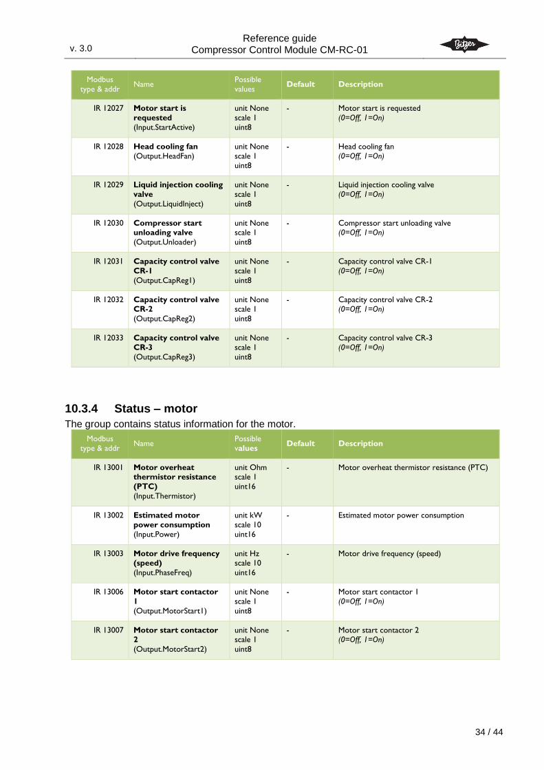
10.3.4 Status – motor
The group contains status information for the motor.
Modbus
type & addr Name
Possible
values Default Description
IR 13001 Motor overheat thermistor resistance
(PTC)
(Input.Thermistor)
unit Ohm scale 1
uint16
- Motor overheat thermistor resistance (PTC)
IR 13002 Estimated motor
power consumption
(Input.Power)
unit kW
scale 10
uint16
- Estimated motor power consumption
IR 13003 Motor drive frequency (speed)
(Input.PhaseFreq)
unit Hz scale 10
uint16
- Motor drive frequency (speed)
IR 13006 Motor start contactor
1
(Output.MotorStart1)
unit None
scale 1
uint8
- Motor start contactor 1
(0=Off, 1=On)
IR 13007 Motor start contactor 2
(Output.MotorStart2)
unit None scale 1
uint8
- Motor start contactor 2 (0=Off, 1=On)
v. 3.0
Reference guide Compressor Control Module CM-RC-01
3.0
35 / 44
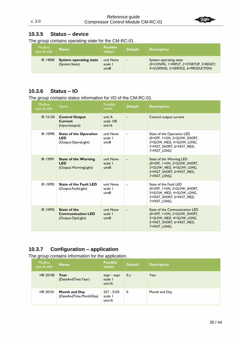
10.3.5 Status – device
The group contains operating state for the CM-RC-01.
Modbus
type & addr Name
Possible
values Default Description
IR 14000 System operating state
(System.State)
unit None
scale 1
uint8
- System operating state
(0=CONFIG, 1=INPUT, 2=STARTUP, 3=READY,
4=SUSPEND, 5=SERVICE, 6=PRODUCTION)
10.3.6 Status – IO
The group contains status information for I/O of the CM-RC-01.
Modbus type & addr
Name Possible values
Default Description
IR 15150 Control Output
Current
(Input.Ioutput)
unit A
scale 100
sint16
- Control output current
IR 15990 State of the Operation LED
(Output.OperaLight)
unit None scale 1
uint8
- State of the Operation LED (0=OFF, 1=ON, 2=SLOW_SHORT,
3=SLOW_MED, 4=SLOW_LONG,
5=FAST_SHORT, 6=FAST_MED,
7=FAST_LONG)
IR 15991 State of the Warning
LED
(Output.WarningLight)
unit None
scale 1
uint8
- State of the Warning LED
(0=OFF, 1=ON, 2=SLOW_SHORT,
3=SLOW_MED, 4=SLOW_LONG,
5=FAST_SHORT, 6=FAST_MED,
7=FAST_LONG)
IR 15992 State of the Fault LED
(Output.FaultLight)
unit None
scale 1
uint8
- State of the Fault LED
(0=OFF, 1=ON, 2=SLOW_SHORT,
3=SLOW_MED, 4=SLOW_LONG,
5=FAST_SHORT, 6=FAST_MED,
7=FAST_LONG)
IR 15993 State of the Communication LED
(Output.OptLight)
unit None scale 1
uint8
- State of the Communication LED (0=OFF, 1=ON, 2=SLOW_SHORT,
3=SLOW_MED, 4=SLOW_LONG,
5=FAST_SHORT, 6=FAST_MED,
7=FAST_LONG)
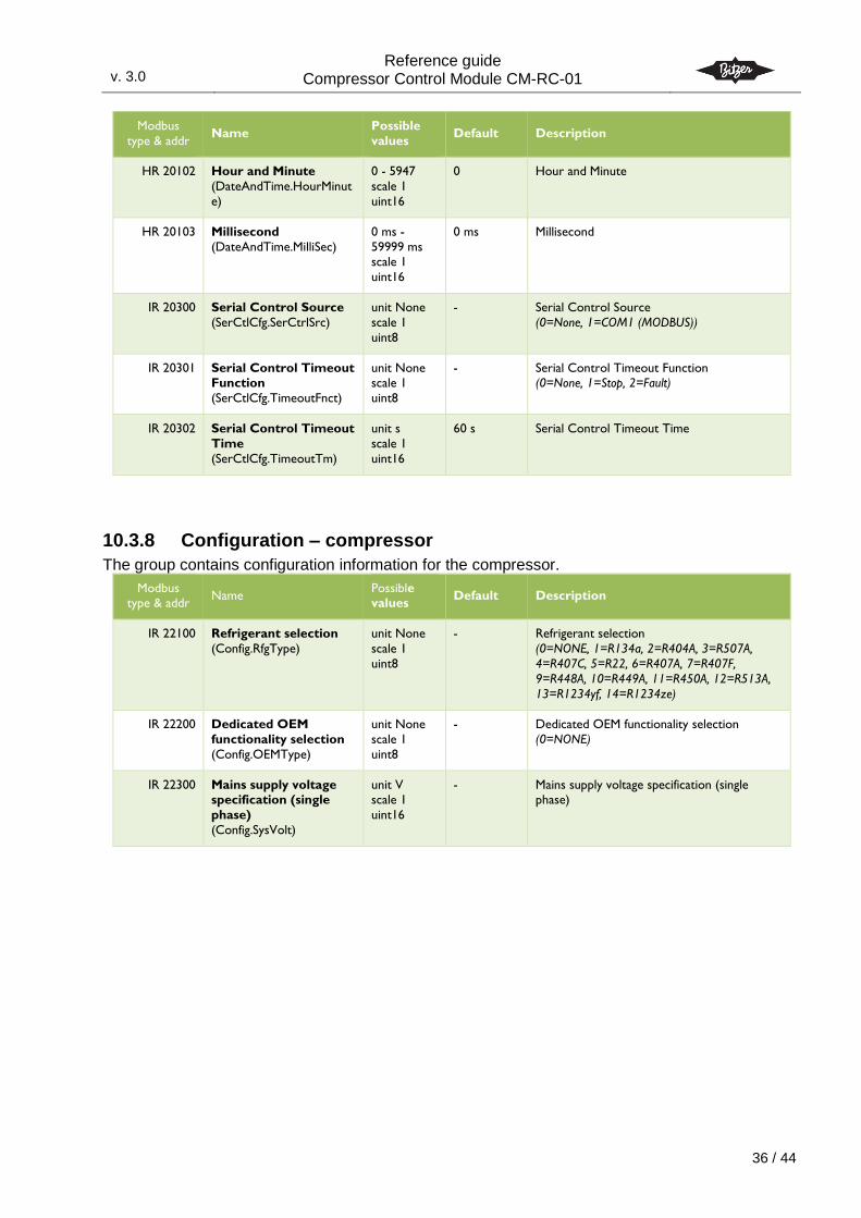
10.3.7 Configuration – application
The group contains information for the application.
Modbus
type & addr Name
Possible
values Default Description
HR 20100 Year (DateAndTime.Year)
expr - expr scale 1
uint16
0 y Year
HR 20101 Month and Day
(DateAndTime.MonthDay)
257 - 3103
scale 1
uint16
0 Month and Day
v. 3.0
Reference guide Compressor Control Module CM-RC-01
3.0
36 / 44
Modbus
type & addr Name
Possible
values Default Description
HR 20102 Hour and Minute
(DateAndTime.HourMinut
e)
0 - 5947
scale 1
uint16
0 Hour and Minute
HR 20103 Millisecond
(DateAndTime.MilliSec)
0 ms -
59999 ms scale 1
uint16
0 ms Millisecond
IR 20300 Serial Control Source
(SerCtlCfg.SerCtrlSrc)
unit None
scale 1
uint8
- Serial Control Source
(0=None, 1=COM1 (MODBUS))
IR 20301 Serial Control Timeout Function
(SerCtlCfg.TimeoutFnct)
unit None scale 1
uint8
- Serial Control Timeout Function (0=None, 1=Stop, 2=Fault)
IR 20302 Serial Control Timeout
Time
(SerCtlCfg.TimeoutTm)
unit s
scale 1
uint16
60 s Serial Control Timeout Time
10.3.8 Configuration – compressor
The group contains configuration information for the compressor.
Modbus type & addr
Name Possible values
Default Description
IR 22100 Refrigerant selection
(Config.RfgType)
unit None
scale 1
uint8
- Refrigerant selection
(0=NONE, 1=R134a, 2=R404A, 3=R507A,
4=R407C, 5=R22, 6=R407A, 7=R407F,
9=R448A, 10=R449A, 11=R450A, 12=R513A,
13=R1234yf, 14=R1234ze)
IR 22200 Dedicated OEM
functionality selection
(Config.OEMType)
unit None
scale 1
uint8
- Dedicated OEM functionality selection
(0=NONE)
IR 22300 Mains supply voltage specification (single
phase)
(Config.SysVolt)
unit V scale 1
uint16
- Mains supply voltage specification (single phase)
v. 3.0
Reference guide Compressor Control Module CM-RC-01
3.0
37 / 44
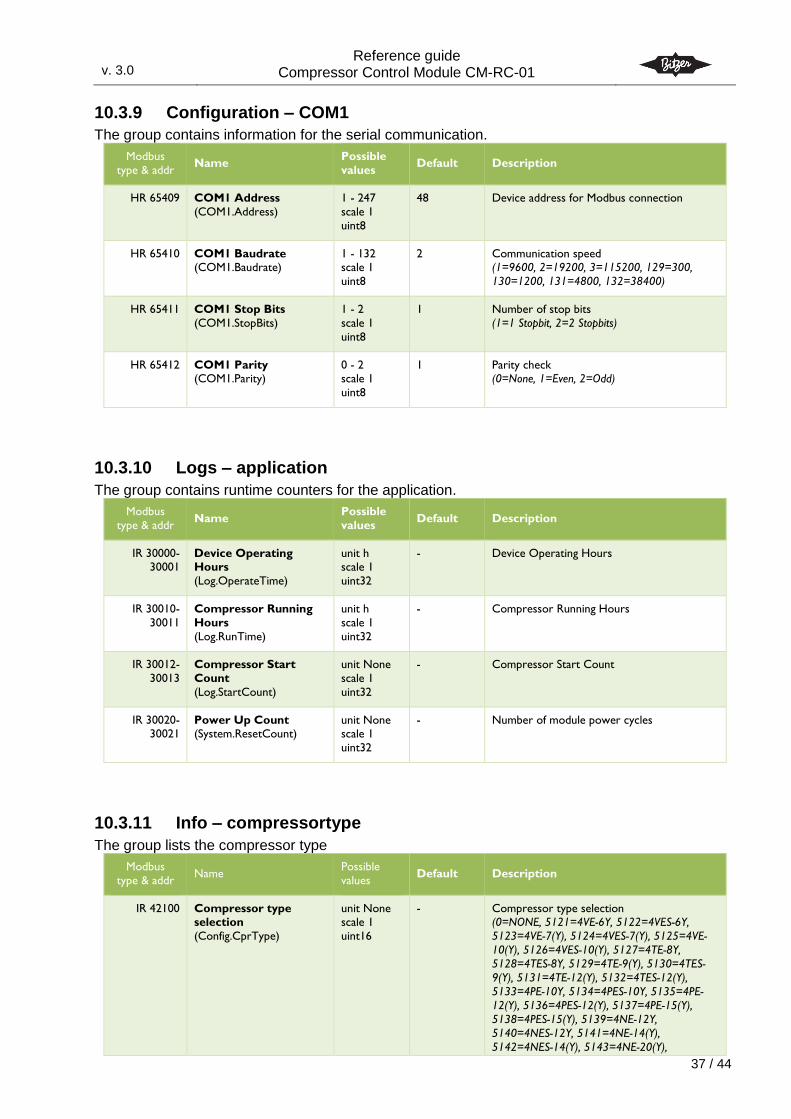
10.3.9 Configuration – COM1
The group contains information for the serial communication.
Modbus
type & addr Name
Possible
values Default Description
HR 65409 COM1 Address
(COM1.Address)
1 - 247
scale 1
uint8
48 Device address for Modbus connection
HR 65410 COM1 Baudrate (COM1.Baudrate)
1 - 132 scale 1
uint8
2 Communication speed (1=9600, 2=19200, 3=115200, 129=300,
130=1200, 131=4800, 132=38400)
HR 65411 COM1 Stop Bits
(COM1.StopBits)
1 - 2
scale 1
uint8
1 Number of stop bits
(1=1 Stopbit, 2=2 Stopbits)
HR 65412 COM1 Parity (COM1.Parity)
0 - 2 scale 1
uint8
1 Parity check (0=None, 1=Even, 2=Odd)
10.3.10 Logs – application
The group contains runtime counters for the application.
Modbus
type & addr Name
Possible
values Default Description
IR 30000-30001
Device Operating Hours
(Log.OperateTime)
unit h scale 1
uint32
- Device Operating Hours
IR 30010-
30011
Compressor Running
Hours
(Log.RunTime)
unit h
scale 1
uint32
- Compressor Running Hours
IR 30012-
30013
Compressor Start
Count
(Log.StartCount)
unit None
scale 1
uint32
- Compressor Start Count
IR 30020-30021
Power Up Count (System.ResetCount)
unit None scale 1
uint32
- Number of module power cycles
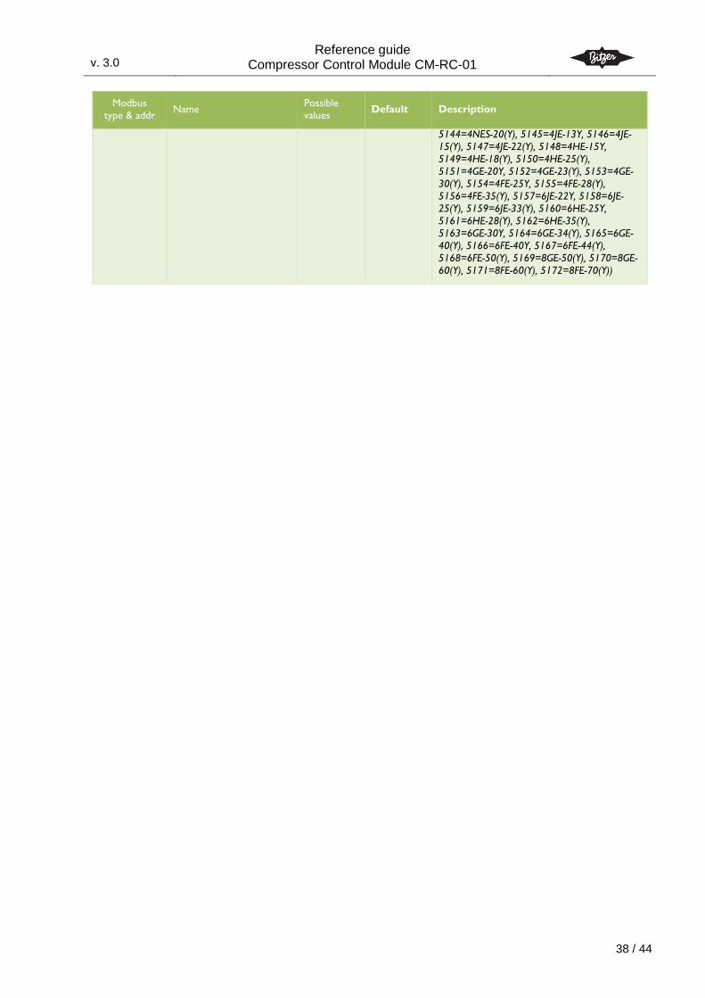
10.3.11 Info – compressortype
The group lists the compressor type
Modbus
type & addr Name
Possible
values Default Description
IR 42100 Compressor type selection
(Config.CprType)
unit None scale 1
uint16
- Compressor type selection (0=NONE, 5121=4VE-6Y, 5122=4VES-6Y,
5123=4VE-7(Y), 5124=4VES-7(Y), 5125=4VE-
10(Y), 5126=4VES-10(Y), 5127=4TE-8Y,
5128=4TES-8Y, 5129=4TE-9(Y), 5130=4TES-
9(Y), 5131=4TE-12(Y), 5132=4TES-12(Y),
5133=4PE-10Y, 5134=4PES-10Y, 5135=4PE-
12(Y), 5136=4PES-12(Y), 5137=4PE-15(Y),
5138=4PES-15(Y), 5139=4NE-12Y,
5140=4NES-12Y, 5141=4NE-14(Y),
5142=4NES-14(Y), 5143=4NE-20(Y),
v. 3.0
Reference guide Compressor Control Module CM-RC-01
3.0
38 / 44
Modbus
type & addr Name
Possible
values Default Description
5144=4NES-20(Y), 5145=4JE-13Y, 5146=4JE-
15(Y), 5147=4JE-22(Y), 5148=4HE-15Y,
5149=4HE-18(Y), 5150=4HE-25(Y),
5151=4GE-20Y, 5152=4GE-23(Y), 5153=4GE-
30(Y), 5154=4FE-25Y, 5155=4FE-28(Y),
5156=4FE-35(Y), 5157=6JE-22Y, 5158=6JE-
25(Y), 5159=6JE-33(Y), 5160=6HE-25Y,
5161=6HE-28(Y), 5162=6HE-35(Y),
5163=6GE-30Y, 5164=6GE-34(Y), 5165=6GE-
40(Y), 5166=6FE-40Y, 5167=6FE-44(Y),
5168=6FE-50(Y), 5169=8GE-50(Y), 5170=8GE-
60(Y), 5171=8FE-60(Y), 5172=8FE-70(Y))
v. 3.0
Reference guide Compressor Control Module CM-RC-01
3.0
39 / 44
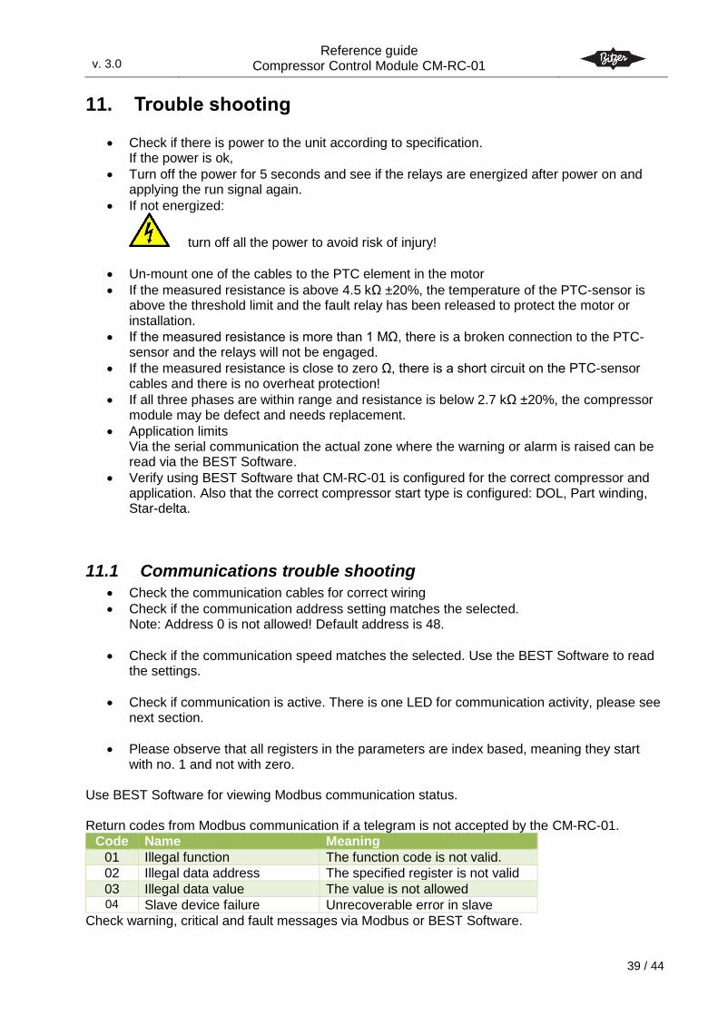
11. Trouble shooting
Check if there is power to the unit according to specification. If the power is ok,
Turn off the power for 5 seconds and see if the relays are energized after power on and applying the run signal again.
If not energized:
turn off all the power to avoid risk of injury!
Un-mount one of the cables to the PTC element in the motor
If the measured resistance is above 4.5 kΩ ±20%, the temperature of the PTC-sensor is above the threshold limit and the fault relay has been released to protect the motor or installation.
If the measured resistance is more than 1 MΩ, there is a broken connection to the PTC-sensor and the relays will not be engaged.
If the measured resistance is close to zero Ω, there is a short circuit on the PTC-sensor cables and there is no overheat protection!
If all three phases are within range and resistance is below 2.7 kΩ ±20%, the compressor module may be defect and needs replacement.
Application limits Via the serial communication the actual zone where the warning or alarm is raised can be read via the BEST Software.
Verify using BEST Software that CM-RC-01 is configured for the correct compressor and application. Also that the correct compressor start type is configured: DOL, Part winding, Star-delta.
11.1 Communications trouble shooting
Check the communication cables for correct wiring
Check if the communication address setting matches the selected. Note: Address 0 is not allowed! Default address is 48.
Check if the communication speed matches the selected. Use the BEST Software to read the settings.
Check if communication is active. There is one LED for communication activity, please see next section.
Please observe that all registers in the parameters are index based, meaning they start with no. 1 and not with zero.
Use BEST Software for viewing Modbus communication status. Return codes from Modbus communication if a telegram is not accepted by the CM-RC-01.
Code Name Meaning
01 Illegal function The function code is not valid.
02 Illegal data address The specified register is not valid
03 Illegal data value The value is not allowed 04 Slave device failure Unrecoverable error in slave
Check warning, critical and fault messages via Modbus or BEST Software.
v. 3.0
Reference guide Compressor Control Module CM-RC-01
3.0
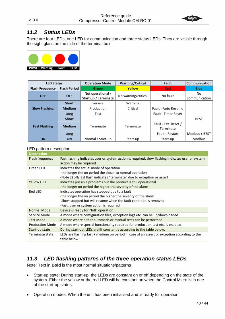
40 / 44
11.2 Status LEDs There are four LEDs, one LED for communication and three status LEDs. They are visible through the sight glass on the side of the terminal box.
LED Status Operation Mode Warning/Critical Fault Communication
Flash Frequency Flash Period Green Yellow Red Blue
OFF OFF Not operational /
Start-up / Terminate No warning/critical No fault
No communication
Slow Flashing
Short Service Warning
Medium Production Critical Fault - Auto Resume
Long Test Fault - Timer Reset
Fast Flashing
Short BEST
Medium Terminate Terminate Fault - Ext. Reset /
Terminate
Long Fault - Restart Modbus + BEST
ON ON Normal / Start-up Start-up Start-up Modbus
LED pattern description
Description
Flash frequency Fast flashing indicates user or system action is required, slow flashing indicates user or system action may be required
Green LED Indicates the actual mode of operation -the longer the on period the closer to normal operation -Note 2) off/fast flash indicates “terminate” due to exception or assert
Yellow LED Indicates possible problems but the product is still operational -the longer on period the higher the severity of the alarm
Red LED Indicates operation has stopped due to a fault -the longer the on period the higher the severity of the alarm -Slow: stopped but will resume when the fault condition is removed -Fast: user or system action is required
Normal Mode Device is ready for "full" operation
Service Mode A mode where configuration files, exception logs etc. can be up/downloaded
Test Mode A mode where either automatic or manual tests can be performed
Production Mode A mode where special functionality required for production test etc. is enabled
Start-up state During start-up, LEDs are lit constantly according to the table below.
Terminate state LEDs are flashing fast + medium on period in case of an assert or exception according to the table below
11.3 LED flashing patterns of the three operation status LEDs Note: Text in Bold is the most normal situations/patterns
Start-up state: During start-up, the LEDs are constant on or off depending on the state of the system. Either the yellow or the red LED will be constant on when the Control Micro is in one of the start-up states.
Operation modes: When the unit has been initialised and is ready for operation.
v. 3.0
Reference guide Compressor Control Module CM-RC-01
3.0
41 / 44
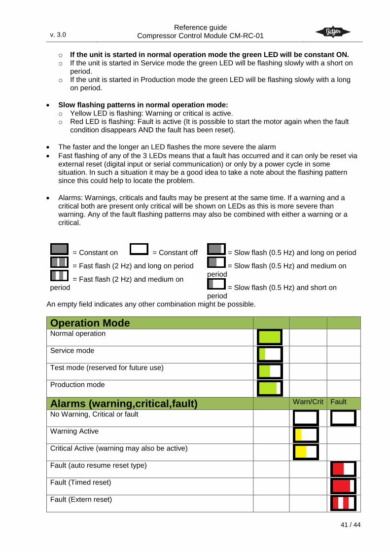
o If the unit is started in normal operation mode the green LED will be constant ON. o If the unit is started in Service mode the green LED will be flashing slowly with a short on
period. o If the unit is started in Production mode the green LED will be flashing slowly with a long
on period.
Slow flashing patterns in normal operation mode: o Yellow LED is flashing: Warning or critical is active. o Red LED is flashing: Fault is active (It is possible to start the motor again when the fault
condition disappears AND the fault has been reset).
The faster and the longer an LED flashes the more severe the alarm
Fast flashing of any of the 3 LEDs means that a fault has occurred and it can only be reset via external reset (digital input or serial communication) or only by a power cycle in some situation. In such a situation it may be a good idea to take a note about the flashing pattern since this could help to locate the problem.
Alarms: Warnings, criticals and faults may be present at the same time. If a warning and a critical both are present only critical will be shown on LEDs as this is more severe than warning. Any of the fault flashing patterns may also be combined with either a warning or a critical.
= Constant on = Constant off
= Fast flash (2 Hz) and long on period
= Fast flash (2 Hz) and medium on period
= Slow flash (0.5 Hz) and long on period
= Slow flash (0.5 Hz) and medium on period
= Slow flash (0.5 Hz) and short on period
An empty field indicates any other combination might be possible.
Operation Mode
Normal operation
Service mode
Test mode (reserved for future use)
Production mode
Alarms (warning,critical,fault) Warn/Crit Fault
No Warning, Critical or fault
Warning Active
Critical Active (warning may also be active)
Fault (auto resume reset type)
Fault (Timed reset)
Fault (Extern reset)
v. 3.0
Reference guide Compressor Control Module CM-RC-01
3.0
42 / 44
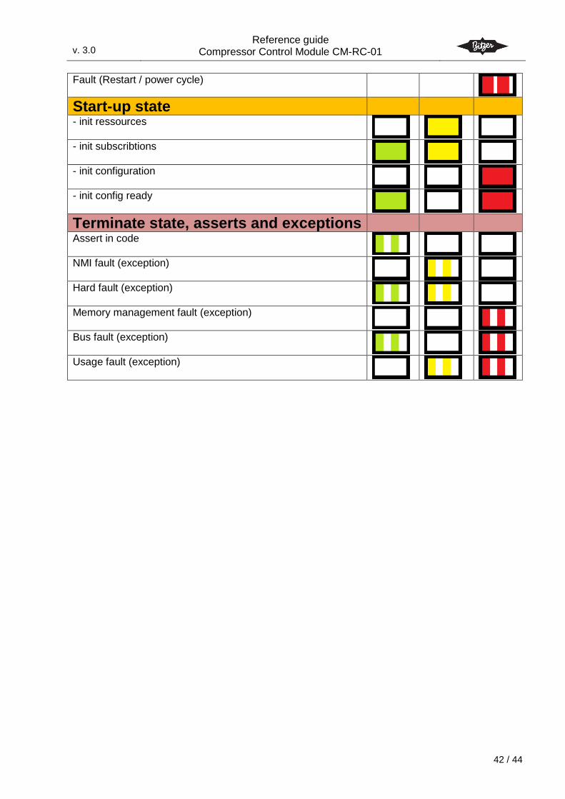
Fault (Restart / power cycle)
Start-up state
- init ressources
- init subscribtions
- init configuration
- init config ready
Terminate state, asserts and exceptions
Assert in code
NMI fault (exception)
Hard fault (exception)
Memory management fault (exception)
Bus fault (exception)
Usage fault (exception)
v. 3.0
Reference guide Compressor Control Module CM-RC-01
3.0
43 / 44
12. Notes . . . . . . . . . . . . . . . . . . . . . . . . . . . . . . . . . . . . . . . . . . . . . . . . . . . . . . . . . . . . . . . . . . . . . . . . . . . . . . . . . . . . . . . . . . . . . . . . . . . . . . . . . . . . . . . . . . . . . . . . . . . . . . . . . . . . . . . . . . . . . . . . . . . . . . . . . . . . . . . . . . . . . . . . . . . . . . . . . . . . . . . . . . . . . . . . . . . . . . . . . . . . . . . . . . . . . . . . . . . . . . . . . . . . . . . . . . . . . . . . . . . . . . . . . . . . . . . . . . . . . . . . . . . . . . . . . . . . . . . . . . . . . . . . . . . . . . . . . . . . . . . . . . . . . . . . . . . . . . . . . . . . . . . . . . . . . . . . . . . . . . . . . . . . . . . . . . . . . . . . . . . . . . . . . . . . . . . . . . . . . . . . . . . . . . . . . . . . . . . . . . . . . . . . . . . . . . . . . . . . . . . . . . . . . . . . . . . . . . . . . . . . . . . . . . . . . . . . . . . . . . . . . . . . . . . . . . . . . . . . . . . . . . . . . . . . . . . . . . . . . . . . . . . . . . . . . . . . . . . . . . . . . . . . . . . . . . . . . . . . . . . . . . . . . . . . . . . . . . . . . . . . . . . . . . . . . . . . . . . . . . . . . . . . . . . . . . . . . . . . . . . . . . . . . . . . . . . . . . . . . . . . . . . . . . . . . . . . . . . . . . . . . . . . . . . . . . . . . . . . . . . . . . . . . . . . . . . . . . . . . . . . . . . . . . . . . . . . . . . . . . . . . . . . . . . . . . . . . . . . . . . . . . . . . . . . . . . . . . . . . . . . . . . . . . . . . . . . . . . . . . . . . . . . . . . . . . . . . . . . . . . . . . . . . . . . . . . . . . . . . . . . . . . . . . . . . . . . . . . . . . . . . . . . . . . . . . . . . . . . . . . . . . . . . . . . . . . . . . . . . . . . . . . . . . . . . . . . . . . . . . . . . . . . . . . . . . . . . . . . . . . . . . . . . . . . . . . . . . . . . . . . . . . . . . . . . . . . . . . . . . . . . . . . . . . . . . . . . . . . . . . . . . . . . . . . . . . . . . . . . . . . . . . . . . . . . . . . . . . . . . . . . . . . . . . . . . . . . . . . . . . . . . . . . . . . . . . . . . . . . . . . . . . . . . . . . . . . . . . . . . . . . . . . . . . . . . . . . . . . . . . . . . . . . . . . . . . . . . . . . . . . . . . . . . . . . . . . . . . . . . . . . . . . . . . . . . . . . . . . . . . . . . . . . . . . . . . . . . . . . . . . . . . . . . . . . . . . . . . . . . . . . . . . . . . . . . . . . . . . . . . . . . . . . . . . . . . . . . . . . . . . . . . . . . . . . . . . . . . . . . . . . . . . . . . . . . . . . . . . . . . . . . . . . . . . . . . . . . . . . . . . . . . . . . . . . . . . . . . . . . . . . . . . . . . . . . . . . . . . . . . . . . . . . . . . . . . . . . . . . . . . . . . . . . . . . . . . . . . . . . . . . . . . . . . . . . . . . . . . . . . . . . . . . . . . . . . . . . . . . . . . . . . . . . . . . . . . . . . . . . . . . . . . . . . . . . . . . . . . . . . . . . . . . . . . . . . . . . . . . . . . . . . . . . . . . . . . . . . . . . . . . . . . . . . . . . . . . . . . . . . . . . . . . . . . . . . . . . . . . . . . . . . . . . . . . . . . . . . . . . . . . . . . . . . . . . . . . . . . . . . . . . . . . . . . . . . . . . . . . . . . . . . . . . . . . . . . . . . . . . . . . . . . . . . . . . . . . . . . . . . . . . . . . . . . . . . . . . . . . . . . . . . . . . . . . . . . . . . . . . . . . . . . . . . . . . . . . . . . . . . . . . . . . . . . . . . . . . . . . . . . . . . . . . . . . . . . . . . . . . . . . . . . . . . . . . . . . . . . . . . . . . . . . . . . . . . . . . . . . . . . . . . . . . . . . . . . . . . . . . . . . . . . . . . . . . . . . . . . . . . . . . . . . . . . . . . . . . . . . . . . . . . . . . . . . . . . . . . . . . . . . . . . . . . . . . . . . . . . . . . . . . . . . . . . . . . . . . . . . . . . . . . . . . . . . . . . . . . . . . . . . . . . . . . . . . . . . . . . . . . . . . . . . . . . . . . . . . . . . . . . . . . . . . . . . . . . . . . . . . . . . . . . . . . . . . . . . . . . . . . . . . . . . . . . . . . . . . . . . . . . . . . . . . . . . . . . . . . . . . . . . . . . . . . . . . . . . . . . . . . . . . . . . . . . . . . . . . . . . . . . . . . . . . . . . . . . . . . . . . . . . . . . . . . . . . . . . . . . . . . . . . . . . . . . . . . . . . . . . . . . . . . . . . . . . . . . . . . . . . . . . . . . . . . . . . . . . . . . . . . . . . . . . . . . . . . . . . . . . . . . . . . . . . . . . . . . . . . . . . . . . . . . . . . . . . . . . . . . . . . . . . . . . . . . . . . . . . . . . . . . . . . . . . . . . . . . . . . . . . . . . . . . . . . . . . . . . . . . . . . . . . . . . . . . . . . . . . . . . . . . . . . . . . . . . . . . . . . . . . . . . . . . . . . . . . . . . . . . . . . . . . . . . . . . . . . . . . . . . . . . . . . . . . . . . . . . . . . . . . . . . . . . . . . . . . . . . . . . . . . . . . . . . . . . . . . . . . . . . . . . . . . . . . . . . . . . . . . . . . . . . . . . . . . . . . . . . . . . . . . . . . . . . . . . . . . . . . . . . . . . . . . . . . . . . . . . . . . . . . . . . . . . . . . . . . . . . . . . . . . . . . . . . . . . . . . . . . . . . . . . . . . . . . . . . . . . . . . . . . . . . . . . . . . . . . . . . . . . . . . . . . . . . . . . . . . . . . . . . . . . . . . . . . . . . . . . . . . . . . . . . . . . . . . . . . . . . . . . . . . . . . . . . . . . . . . . . . . . . . . . . . . . . . . . . . . . . . . . . . . . . . . . . . . . . . . . . . . . . . . . . . . . . . . . . . . . . . . . . . . . . . . . . . . . . . . . . . . . . . . . . . . . . . . . . . . . . . . . . . . . . . . . . . . . . . . . . . . . . . . . . . . . . . . . . . . . . . . . . . . . . . . . . . . . . . . . . . . . . . . . . . . . . . . . . . . . . . . . . . . . . . . . . . . . . . . . . . . . . . . . . . . . . . . . . . . . . . . . . . . . . . . . . . . . . . . . . . . . . . . . . . . . . . . . . . . . . . . . . . . . . . . . . . . . . . . . . . . . . . . . . . . . . . . . . . . . . . . . . . . . . . . . . . . . . . . . . . . . . . . . . . . . . . . . . . . . . . . . . . . . . . . . . . . . . . . . . . . . . . . . . . . . . . . . . . . . . . . . . . . . . . . . . . . . . . . . . . . . . . . . . . . . . . . . . . . . . . . . . . . . . . . . . . . . . . . . . . . . . . . . . . . . . . . . . . . . . . . . . . . . . . . . . . . . . . . . . . . . . . . . . . . . . . . . . . . . . . . . . . . . . . . . . . . . . . . . . . . . . . . . . . . . . . . . . . . . . . . . . . . . . . . . . . . . . . . . . . . . . . . . . . . . . . . . . . . . . . . . . . . . . . . . . . . . . . . . . . . . . . . . . . . . . . . . . . . . . . . . . . . . . . . . . . . . . . . . . . . . . . . . . . . . . . . . . . . . . . . . . . . . . . . . . . . . . . . . . . . . . . . . . . . . . . . . . . . . . . . . . . . . . . . . . . . . . . . . . . . . . . . . . . . . . . . . . . . . . . . . . . . . . . . . . . . . . . . . . . . . . . . . . . . . . . . . . . . . . . . . . . . . . . . . . . . . . . . . . . . . . . . . . . . . . . . . . . . . . . . . . . . . . . . . . . . . . . . . . . . . . . . . . . . . . . . . . . . . . . . . . . . . . . . . . . . . . . . . . . . . . . . . . . . . . . . . . . . . . . . . . . . . . . . . . . . . . . . . . . . . . . . . . . . . . . . . . . . . . . . . . . . . . . . . . . . . . . . . . . . . . . . . . . . . . . . . . . . . . . . . . . . . . . . . . . . . . . . . . . . . . . . . . . . . . . . . . . . . . . . . . . . . . . . . . . . . . . . . . . . . . . . . . . . . . . . . . . . . . . . . . . . . . . . . . . . . . . . . . . . . . . . . . . . . . . . . . . . . . . . . . . . . . . . . . . . . . . . . . . . . . . . . . . . . . . . . . . . . . . . . . . . . . . . . . . . . . . . . . . . . . . . . . . . . . . . . . . . . . . . . . . . . . . . . . . . . . . . . . . . . . . . . . . . . . . . . . . . . . . . . . . . . . . . . . . . . . . . . . . . . . . . . . . . . . . . . . . . . . . . . . . . . . . . . . . . . . . . . . . . . . . . . . . . . . . . . . . . . . . . . . . . . . . . . . . . . . . . . . . . . . . . . . . . . . . . . . . . . . . . . . . . . . . . . . . . . . . . . . . . . . . . . . . . . . . . . . . . . . . . . . . . . . . . . . . . . . . . . . . . . . . . . . . . . . . . . . . . . . . . . . . . . . . . . . . . . . . . . . . . . . . . . . . . . . . . . . . . . . . . . . . . . . . . . . . . . .
v. 3.0
Reference guide Compressor Control Module CM-RC-01
3.0
44 / 44
BITZER Kühlmaschinenbau GmbH Eschenbrünnlestraße 15 // 71065 Sindelfingen // Germany
Tel +49 (0) 70 31 932-0 // Fax +49 (0) 70 31 932-147 [email protected] // Internet: www.bitzer.de
Ver.
3.0
- 2
6.0
4.2
016 -
Conte
nt is
su
bje
ct to
ch
ang
e w
itho
ut
notice.
![33-00187EFS 01 - Honeywell T4 Pro Series · 4 1H/1C System (1 transformer) R Power [1] Rc [R+Rc joined by Slider Tab] [2] Y Compressor contactor C 24VAC common [3] W Heat relay G](https://img.pdfslide.net/doc/110x75/5eb8158a8e47f055f24c334b/33-00187efs-01-honeywell-t4-pro-series-4-1h1c-system-1-transformer-r-power.jpg)