Embed Size (px)
Citation preview

© Siemens AG 2008. All rights reserved.
Compressors, an introduction
Dynaflow
2009-09-10
Agenda
1. Introduction.
2. Applications
3. Compressor Types
4. Centrifugal compressorworking principles
5. Compressor selection
6. Mechanical design
7. Aerodynamics
8. Rotordynamics
EnergyOil&Gas SolutionsRotating equipment
Steam turbine Gas turbine Electric motor
Compressor
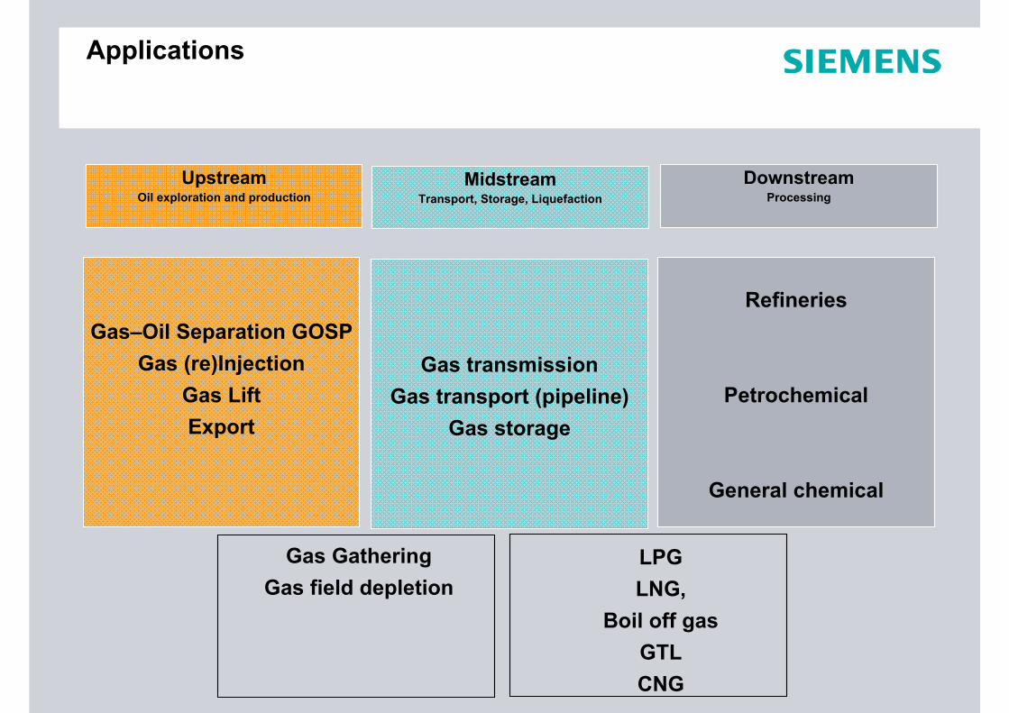
MidstreamTransport, Storage, Liquefaction
UpstreamOil exploration and production
DownstreamProcessing
Applications
LPGLNG,
Boil off gasGTLCNG
Gas GatheringGas field depletion
Gas–Oil Separation GOSPGas (re)Injection
Gas LiftExport
Gas transmissionGas transport (pipeline)
Gas storage
Refineries
Petrochemical
General chemical

STC-GV STC-GC STC-GV
Compressors
STC-SX STC-SR STC-SH STC-SV STC-SP STC-SI
DisplacementDynamic
AxialIntegrally Geared
Radial
Rotarytwo rotorsone rotor
Liquid ringVane Screw RootsLabyrinth Diaphragm
Reciprocating
Single Shaft
Others
Compressor types

Overview Compressor Working Principles
Reciprocating
V1
V2
P2
p1
V1
V2
( )=
Positive Displacement
volume reduction
χ

Overview Compressor Working Principles
Tip diameter
Blade inlet diameter
Eye diameter
Hub diameter
Centrifugal
Velocity increase
1
11
http://www.geocities.com/mojju/me797/Compressors101.swf
2 Compressors types animation.swf

Reciprocating

DynamicCompressor Types
Single shaft compressors
Axial/axial-radialcompressors Integrally geared compressors


Performance characteristic for various compressor types

Application range of different types of compressors
Reciprocating
Screw / Rotary vane / Roots
Turbo radial
Turbo axial-(radial)
Actual suction volume [m3/h]
Dis
char
ge p
ress
ure
[bar
]
MD experimental
Naptha Cracking (Ethylene)
Gaslift
Ammonia Synthesis, Hydrocracking
Reinjection
Polyethylene

No pulsations
Lower foundation cost and civil cost
Minimum weight and space
No wearing parts
Reliability and availability
Low noise emission
Smooth start up and control
Total Cost of Ownership
Turbocompressor
compared to reciprocating
Advantages Disadvantages
Efficiency
CAPEX
Operating range
Delivery time
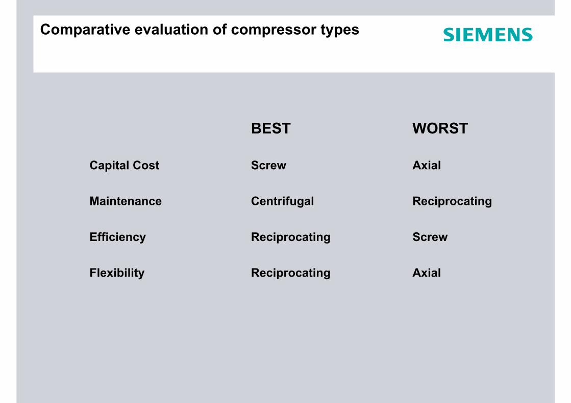
BEST WORST
Capital Cost Screw Axial
Maintenance Centrifugal Reciprocating
Efficiency Reciprocating Screw
Flexibility Reciprocating Axial
Comparative evaluation of compressor types

Agenda
1. Introduction.
2. Applications
3. Compressor Types
4. Centrifugal compressorworking principles
5. Compressor selection
6. Mechanical design
7. Aerodynamics
8. Rotordynamics

Working principle
▲
▲
▲
▲▲
Discharge Suction
Work is done by rotating impellers, increasing the velocity of the gas
Diffusers convert velocity into
pressure
Return vanes guide the flow to the next impeller

Performance curve
0
5
10
15
20
25
30
35
40
45
50
2,000 4,000 6,000 8,000 10,000 12,000 14,000M3/HR
Poly
trop
ic H
ead
[kJ/
kg]
Head is the amount of work necessary to move one unit of mass through the system
⎪⎭
⎪⎬⎫
⎪⎩
⎪⎨⎧
−⎟⎟⎠
⎞⎜⎜⎝
⎛−
=
−
11
1
1
21
nn
pol pp
nnzRTH
Actual volumetric inlet flow
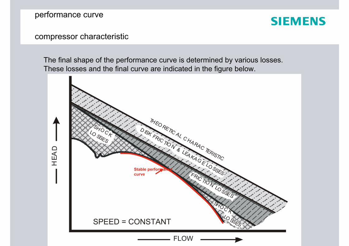
performance curve
compressor characteristic
The final shape of the performance curve is determined by various losses. These losses and the final curve are indicated in the figure below.
THEO RETIC AL C HARAC TERISTIC
D ISK FRIC TIO N & LEA KA G E LO SSESFRIC TIO N LO SSES
SH O C KLO SSES
SHO C KLO SSES
FLOW
HEA
D
SPEED = CONSTANT
Stable performancecurve
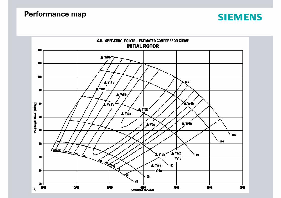
Performance map

Agenda
1. Introduction.
2. Applications
3. Compressor Types
4. Centrifugal compressorworking principles
5. Compressor selection
6. Mechanical design
7. Aerodynamics
8. Rotordynamics

What is the basic function of a compressor?Move a quantity of gas against the head dictated by the system characteristics
p1
T1
gas composition
p2 (p2 > p1)
m•
Selection

Casing/frame size
Impeller diameter, type, flow coefficient
Rotational speed
Number of impellers
Required power
Performance Map
FlowPressureTemperature CompositionProcess variation
Volume flowHead
Mechanical constraints Available drivers
Selection
OutputInput

Impellers
Master blade contour
SmallerFlow
or lowertemperature
Larger Hub to Tip ratio
LargerPressure ratio
or larger Mol weight

Impellers
Q.H. OPERATING POINTS + ESTIMATED IINITAL + INTERMEDIATE + FUTURE COMPRESSOR CURVE
lc17
lc18
lc6
2002
2002
+1.52004
2004
(60)
2006
2009
2012
2013
lc2
lc3
lc4
lc5
lc7lc8
lc9lc1
0
lc11
lc12
lc13
lc14
lc15lc1
6lc1
9lc2
0
ec2
ec2
ec3
ec4
ec5
ec6
ec7
ec8ec9
ec10
ec11
ec12
ec13
ec14
ec15
ec16
ec17
ec18
hc3 hc3
hc4
hc5
hc6
105100
90
70
50
SURGE
657072
7374
74.5
68.5
0.00
25.00
50.00
75.00
100.00
125.00
150.00
175.00
200.00
0 500 1000 1500 2000 2500 3000 3500 4000 4500 5000
Q volume [m^3/hr]
Poly
trop
ic H
ead
[kJ/
kg]
INITIAL ROTOR2 + 2 impellers parallel
FUTURE ROTOR3 + 3 impellers in series
INITIAL ROTOR2 + 2 impellers in series - SAME ROTOR
- CHANGE PIPING
- NEW ROTOR- SAME PIPING

Agenda
1. Introduction.
2. Applications
3. Compressor Types
4. Centrifugal compressorworking principles
5. Compressor selection
6. Mechanical design
7. Aerodynamics
8. Rotordynamics

Page 2 E O OS REDynaflow: 10/09/2009
Compressor Mechanical designExploded view

Page 3 E O OS REDynaflow: 10/09/2009
Compressor Mechanical design Main parts
1 Casing:The casing is designed towithstand the pressure inside the compressor and contains the basic compressor components.
2 Inner barrel:The inner barrel contains the aero assembly and the rotor.

Page 4 E O OS REDynaflow: 10/09/2009
Compressor Mechanical design Main parts
5 Bearing brackets:Supports the axial and radial bearings
4 End Sealing:Makes the compressorgas tight.
3 Rotor:A shaft with impellers and a balance drum
6 Probes:Measure vibration level and axial displacements.

Page 5 E O OS REDynaflow: 10/09/2009
Compressor Mechanical design Compressor Casing
SV-B SH-B

Page 6 E O OS REDynaflow: 10/09/2009
Compressor Mechanical design Flowpath in the compressor
Inlet Plenum
Volute
Inlet Nozzle
DischargeNozzle
Compressor Stage
Spool Piece (not standard in every compressor)
Inner assembly
DiaphragmsRotor
Aero AssemblyInner assembly
Inner barrel

Page 7 E O OS REDynaflow: 10/09/2009
Compressor Mechanical design Inner assembly of bundle
rotor
aero assembly
Inner assembly

Page 8 E O OS REDynaflow: 10/09/2009
Compressor Mechanical design Aero assembly
Diaphragms
Aero Assembly
Inner barrel

Page 9 E O OS REDynaflow: 10/09/2009
Compressor Mechanical design Diaphragms
The main function of diaphragms is to guide gas to the next compressor stage.
A diaphragm consists of 2 parts, a front plate and a back plate. The front plate of the first (1) and the back plate of a second (2) diaphragm together form the vanelessdiffuser and the return passage to the inlet of the next impeller.
Complete Diaphragmassembly
Return Channel Blades
11 2
The diffusers are usual vaneless, but for some applications LSVs are applied.

Page 10 E O OS REDynaflow: 10/09/2009
Compressor Mechanical design Diffuser types
Diffussor types and differences:
-Vaneless-Lower Head and efficiency
-Wider flow range
-Vaned-Higher Head and efficiency
-Smaller flow range

Page 11 E O OS REDynaflow: 10/09/2009
Compressor Mechanical design Return vanes

Page 12 E O OS REDynaflow: 10/09/2009
Compressor Mechanical design Return vanes
Flow

Page 13 E O OS REDynaflow: 10/09/2009
Typical compressor partsFlow distribution of Inlet plenum with spoolpiece

Page 14 E O OS REDynaflow: 10/09/2009
Typical compressor partsMilled volute

Page 15 E O OS REDynaflow: 10/09/2009
Typical compressor partsRotor
The rotor assembly consists of a shaft fitted with the following parts:1 Thrust collar2 Balance drum3 Coupling hub4 Impeller(s) 5 Shaft
Back-to-back Rotor
123
5
4 In-line Rotor
The impellers are shrunk on to the shaft and positioned by a locating ring.

Page 16 E O OS REDynaflow: 10/09/2009
Typical compressor partsLabyrinths
Labyrinth seals can be found:
- 2 at each impeller.
- Between the end sealing and the impellers
- On the balance drum
- Where the shaft protrudes from the bearingbracket
Function:
- Minimizing recycle lossesSeal
GasShaft

Page 17 E O OS REDynaflow: 10/09/2009
Compressor Mechanical design Impeller manufacturing
1. BrazingBrazingmaterial
ShroudBladeDisc
2. Inside weldingWeldingseam
3. Slot weldingSlot seam

Page 18 E O OS REDynaflow: 10/09/2009
Compressor Mechanical design Compressor End
Bearing bracketRadial and Axial Oil bearings
End SealingDry Gas seal, Barrier seal, Labyrinth
Probes

Page 19 E O OS REDynaflow: 10/09/2009
Compressor Mechanical design Active Magnetic Bearings
Dry gas seal cartridge
Rotor
Sensor
Auxiliary bearing
Magnetic radial bearing
Auxiliary bearing
Sensor
ImpellerDry gas seal cartridge
Technical Data:Type: STC-SV-08-3-APower: 5186 kWn: 12128 1/min P1: 32 bar gP2: 56 bar gMedium: Natural Gas

Page 20 E O OS REDynaflow: 10/09/2009
Compressor Mechanical design ECO type compressor
Compressor section
Compressor / motor rotor
Motorsection
Motor casing
Bottom end radial AMB
Bottom back-up bearing
Top end radialAMB
Compressor casing
Axial AMB
Top back-upbearingDue to integral design:
-No protruding shaft
-No end sealing
-No lube oil

Page 21 E O OS REDynaflow: 10/09/2009
1. Introduction.
2. Applications
3. Compressor Types
4. Centrifugal compressorworking principles
5. Compressor selection
6. Mechanical design
7. Aerodynamics
8. Rotordynamics
Agenda

Page 22 E O OS REDynaflow: 10/09/2009
Compressor aerodynamicsInstabilities
The following instabilities occur in a compressor:
SurgePhenomenonProtection
StallPhenomenonImpeller stallDiffuser stall
Noise

Page 23 E O OS REDynaflow: 10/09/2009
Aerodynamic instabilities1. Surge
FLOW
TIME (sec.)1 2 3
PRESSURE
TIME (sec.)1 2 3
TEMPERATURE
TIME (sec.)1 2 3
Major process parameters during surge
Rapid flow oscillations Thrust reversalsPotential damage
Rapid pressure oscillations with process instability
Rising temperatures inside compressor

Page 24 E O OS REDynaflow: 10/09/2009
Aerodynamic instabilities1. Surge
Factors leading to onset of surge:Start-upShutdownOperation related:
Surge is harmful to the compressor:Oscillating flow causes rotor vibrationsReversed flow with heats up the gas in the impellers. Rapid changes in axial thrust may damage the thrust bearings. Sudden changes in load may damage the internals as well as the driver.Instable flow and pressure causes problems in process control and equipment.Operating a compressor in surge will reduce its life time.
Conclusion:The message is to avoid surge.Therefore a Anti Surge Control System is installed at each compressor.

Page 25 E O OS REDynaflow: 10/09/2009
Aerodynamic instabilities1. Surge: Control
Typical Anti Surge control
FT TT PT PT
Cooler Controller
FCV
Obtains: Pd/Ps, Ts, V
Stored: Surge controllinePd/Ps = f (V, Ts)
Compressor

Page 26 E O OS REDynaflow: 10/09/2009
Aerodynamic instabilities2. Rotating stall: Phenomenon
Smooth flow
v1, P1
V2, P2
Lift
a
As angle (a) of attack increases:
- Lift increases
- Break away starts
If angle (a) of attack > critical angle:
- Break down of flow
- Lift collapses STALL
aa
Lift (Bernoulli):
- V1 > V2
- P1 < P2
Page 27 E O OS REDynaflow: 10/09/2009
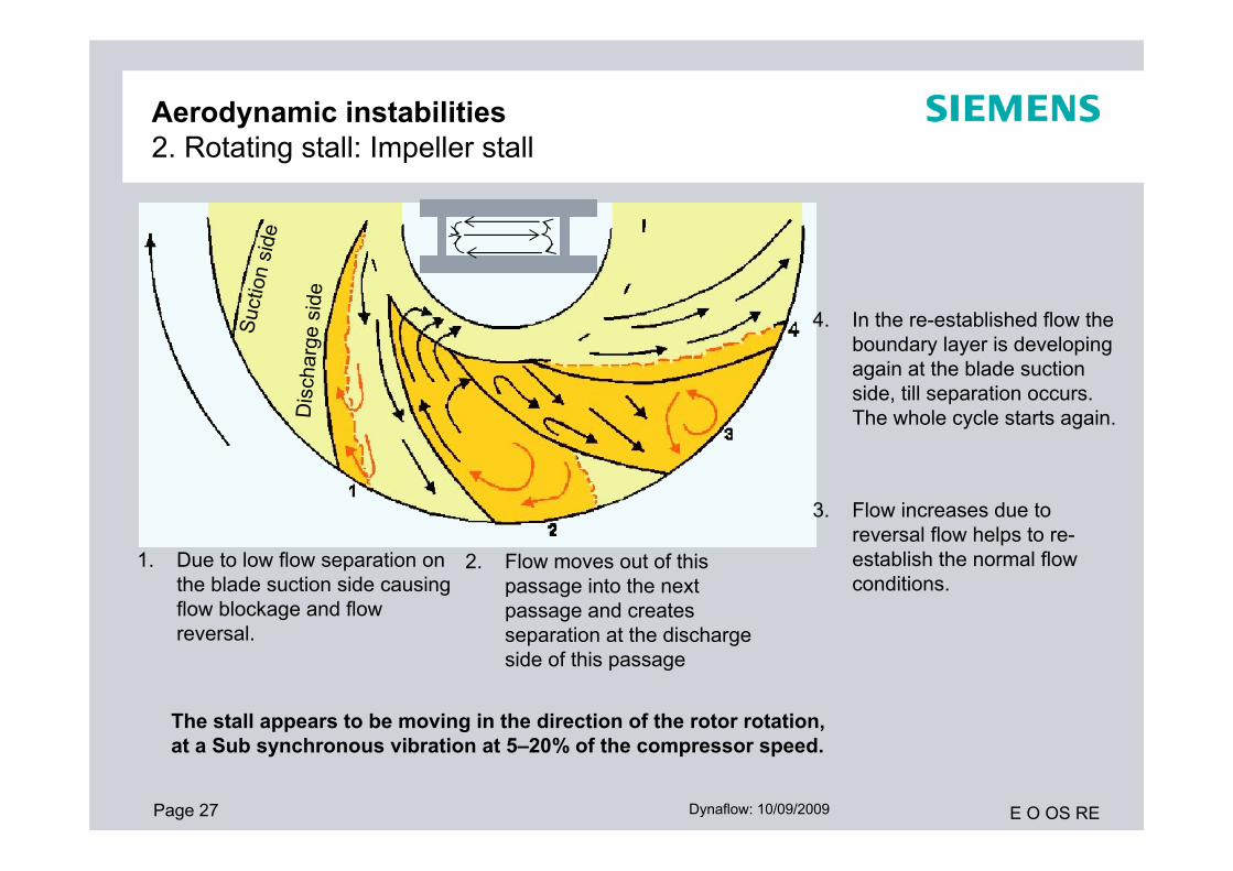
Aerodynamic instabilities2. Rotating stall: Impeller stall
1. Due to low flow separation on the blade suction side causing flow blockage and flow reversal.
2. Flow moves out of this passage into the next passage and creates separation at the discharge side of this passage
Dis
char
ge s
ide
Suct
ion
side
3. Flow increases due to reversal flow helps to re-establish the normal flow conditions.
4. In the re-established flow the boundary layer is developing again at the blade suction side, till separation occurs. The whole cycle starts again.
The stall appears to be moving in the direction of the rotor rotation, at a Sub synchronous vibration at 5–20% of the compressor speed.

Page 28 E O OS REDynaflow: 10/09/2009
Aerodynamic instabilities2. Rotating stall: Vaneless diffuser stall
Diffuser stall is induced by friction:• Friction decreases the gas velocity.
• Mainly effecting radial component.
• Gas stays longer in diffuser.
• Result instable flow = STALL
• Sub synchronous vibration at
7–15% of compressor speed.
Counter measure:• Narrowing diffuser width
Efficiency will drop with increasing flow.
• Apply vaned diffuser
U2
C2 β2W2α2
tang.
rad.
velocityStream lines between stall cells
stall cell
stall cell
stall cell
Page 29 E O OS REDynaflow: 10/09/2009
Aerodynamic instabilitiesNoise
Noise:
SourceAny flow instability causes pressure variations and results is increased noise levels.Especially flow incidence at vanes at high velocity can cause (tonal) noise.
Impeller vanesStator vanesRotor-stator interaction
Counter measuresApply noise-enclosures around the equipment that makes the most noise. This is often a gearbox or a gas turbine.The compressor it selves produces less noise due to the rather thick casing, but the generated noise will be transported forward into the downstream piping.
Movie to visualize rotating stall in a laboratory? (takes few minutes)

Page 30 E O OS REDynaflow: 10/09/2009
1. Introduction.
2. Applications
3. Compressor Types
4. Centrifugal compressorworking principles
5. Compressor selection
6. Mechanical design
7. Aerodynamics
8. Rotordynamics
Agenda

Page 31 E O OS REDynaflow: 10/09/2009
Rotor dynamicsVibrations:
Rotor Vibrations
Lateral Torsional
Self-Excited:
• Oil Whirl
• Labyrinth Induced Whirl
• Thermal Instability
• Aerodynamic Whirl
Rotor Vibrations
Lateral Torsional
Rotor Vibrations
Lateral Torsional
Forced:
• Unbalance
• Rotating Stall
• Surge
• Pressure Pulsation’s
Rotor Vibrations
Lateral Torsional

Page 32 E O OS REDynaflow: 10/09/2009
Rotor dynamicsLateral vibrations
Dynaflow: 10/09/2009
Lateral vibrations
Synchronous Asynchronous
Sub-synchronous
Super-synchronous

Page 33 E O OS REDynaflow: 10/09/2009
RotordynamicsLateral analysis
Lateral Rotor Model
Bearing Span OverhungDE
Overhung NDE

Page 34 E O OS REDynaflow: 10/09/2009
RotordynamicsLateral analysis
Undamped Lateral Critical Speed Map
Operating Speed Range
Undamped Lateral Critical Speeds

Page 35 E O OS REDynaflow: 10/09/2009
RotordynamicsLateral analysis
Undamped Lateral Critical Speed Mode Shapes

Page 36 E O OS REDynaflow: 10/09/2009
RotordynamicsTorsional analysis
0 5000 10000 15000 20000Operating Speed [RPM]
1/Rev
3097
8918
17080
2/Rev
Tors
iona
l Crit
ical
Spee
d [R
PM]
4/Re
v
3/Rev
10000
20000
30000
40000
0
Torsional Critical Speed
Excitation Frequency
Gas Turbine Operating Speed Range
Compressor Operating Speed Range
Campbell Diagram for System Torsional Natural Frequencies
For a torsion analysis the whole rotating string has to be taken into account!

Page 37 E O OS REDynaflow: 10/09/2009
RotordynamicsTorsional analysis
Rotor Configuration with Relative Angular Amplitude
Most Sensitive Element

Page 38 E O OS REDynaflow: 10/09/2009
Rotor dynamicsVibrations:
So far the Rotor dynamics
Proceed with Noise and Mechanical response by Dynaflow

Thank you