Embed Size (px)
Citation preview

COMPUTATION AND MEASUREMENTS OF MASS
TRANSFER AND DISPERSION COEFFICIENTS IN
FLUIDIZED BEDS
Dimitri Gidaspow1
Mayank Kashyap1, Benjapon Chalermsinsuwan2, Veeraya
Jiradilok1
(1) Chemical and Biological Engineering, Illinois Institute of
Technology, 10W 33rd St., Perlstein Hall, Chicago, IL 60616, (2)
Chemical Technology, Chulalongkorn University, Phayathai Road,
Patumwan, Bangkok, 10330, Thailand
DE-FG26-06NT42736
Thursday, April 23, 2009
NETL 2009 Workshop on Multiphase Flow
Science
PROJECT PUBLICATIONS
DISPERSION COEFFICIENTS
• Jiradilok, V., D. Gidaspow, and R.W. Breault, “Computation of gas of solids dispersion
coefficients in turbulent risers and bubbling beds,” Chemical Engineering Science 62 (2007)
3397-3409
• Jiradilok, V., D. Gidaspow, R.W. Breault, L.J. Shadle, C. Gunther, and S. Shi, “Computation of
turbulence and dispersion of cork in the NETL riser”, Chemical Engineering Science 63 (2008)
2135-2148
MASS TRANSFER COEFFICIENTS
• Chalermsinsuwan, B., P. Piumsomboon, and D. Gidaspow, “Kinetic theory based computation
of PSRI riser- Part I: Estimate of mass transfer coefficient”, Chemical Engineering Science, 64
(2009a) 1195-1211
• Chalermsinsuwan, B., P. Piumsomboon, and D. Gidaspow, “Kinetic theory based computation
of PSRI riser- Part II: Computation of mass transfer coefficient with chemical reaction”, Chemical
Engineering Science, 64 (2009b) 1212-1222
• Kashyap, M. and Gidaspow, D, “Measurement of mass transfer coefficients in a bubbling bed
with ozone decomposition”, Paper in preparation
IMPROVED FUTUREGEN CONCEPT
• Gidaspow, D. and V. Jiradilok, “Nanoparticle gasifier fuel cell for sustainable energy future,”
Journal of Power Sources 166 (2007a) 400-410
• Gidaspow, D. and V. Jiradilok, “Efficient Coal Gasifier-Fuel Cell with CO2 Sequestration,” The
Clearwater Coal Conference, The 32nd International Technical Conference on Coal Utilization &
Fuel Systems, Clearwater, Florida, U.S.A. June 13, 2007b
kmkvkkt
kk&=⋅∇+
∂
∂)(
)(ερ
ερ
[ ] kk
N
l
klkkkkkkkkkk vmvvgvv
t
v ~)(~)()(
&+−+⋅∇+=⋅∇+∂
∂∑βτρεερ
ερ
[ ] [ ][ ] [ ]
[ ] [ ] [ ]IvvvS
SIvP
k
T
kkk
kkkkkk
⋅∇−∇+∇=
+∇+−=
3
1)(
2
1
2µξτ
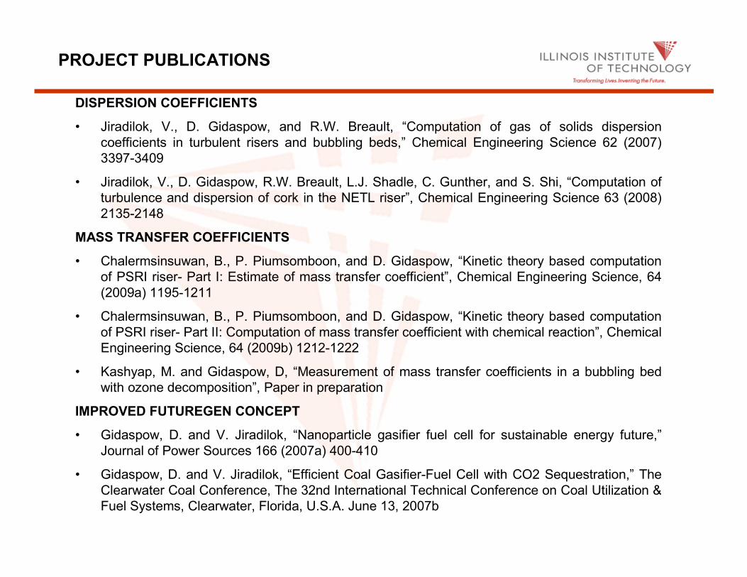
• Continuity Equation for Phase k
• Momentum Equation for Phase k
acceleration of phase ‘k’ = buoyancy + stress + drag force + phase change
• Constitutive Equation for Stress (Above Min. Fluidization)
Kinetic Theory ModelKinetic Theory Model

[ ]sosss geP εθερ )1(21 ++=kinetic collision
- Solid-phase Pressure
• Solid Phase Stress
- Solid-phase Bulk Viscosity
πθ
ρελ )1(3
4 2 egd ossss +=
- Solid-phase Shear Viscosity
( ) πθ
ρεεµ
µ )1(5
4)1(
5
41
1
22
0
egdgege
osssso
s
sdil ++
+++
=
- Radial distribution function - Solid-phase dilute viscosity
[Bagnold(1954)]
13/1
max,
1
−
−=
s
sog ε
ε2
1
96
5θρ
πµ pps d
dil=

)3
1( 2 ><= Cθ
θββγτθρεθρε ApgAssssssss CCqvvt
3:)()(2
3−>⋅<+−−∇=
⋅∇+∂∂
• Fluctuating Energy Equation
- Collisional Energy Dissipation
( )
⋅∇−−= s
s
osss vd
geπθ
θρεγ4
13 22
- Conductivity of Fluctuating Energy
( ) πθ
ρεκεκ )1(2)1(5
61
1
2 2
2
0
egdgege
osssdilso ++
+++
=
21
384
75θπρκ ssdil d=
-Dilute Phase (Eddy Type) Granular Conductivity
)( θκ∇−=q

4
3
8.0for drag, sphere singleon Based -
75.1)(
150
8.0for equation,Ergun on Based -
65.2
2
2
−−
=
>
−+=
<
g
sp
sggsg
d
g
sp
sgsg
spg
gs
g
d
vvC
d
vv
d
εφ
εερβ
ε
φ
ερ
φε
µεβ
ε
[ ]
g
sgpgg
p
pd
pp
p
d
vvd
C
C
µ
ρε −=
>=
<+=
Re
1000 Refor 44.0
1000 Refor Re15.01Re
24 687.0
where,
• Gas-Solid Drag Coefficients

A BRIEF REVIEW
0
1
2
3
4
5
6
7
8
0.70 0.80 0.90 1.00
Bed Void
Heig
ht,
m
Simulation
Experiment
Jiradilok et al. (2006), Chem. Eng. Sci. 61, 5544-5559
Wei et al. (1998) FCC riser
TURBULENT FLOW REGIME

COMPUTED ENERGY SPECTRUM COMPARED COMPUTED ENERGY SPECTRUM COMPARED
TO SINGLE PHASE TURBULENT FLOWTO SINGLE PHASE TURBULENT FLOW
( )fyy
yy
vv
nEv
Λ′′
0.0001
0.001
0.01
0.1
1
10
0.001 0.01 0.1 1 10 100
Wall Region
Central Region
Single Phase Flow
y
f
v
nΛ
Jiradilok et al. (2006), Chem. Eng. Sci. 61, 5544-5559
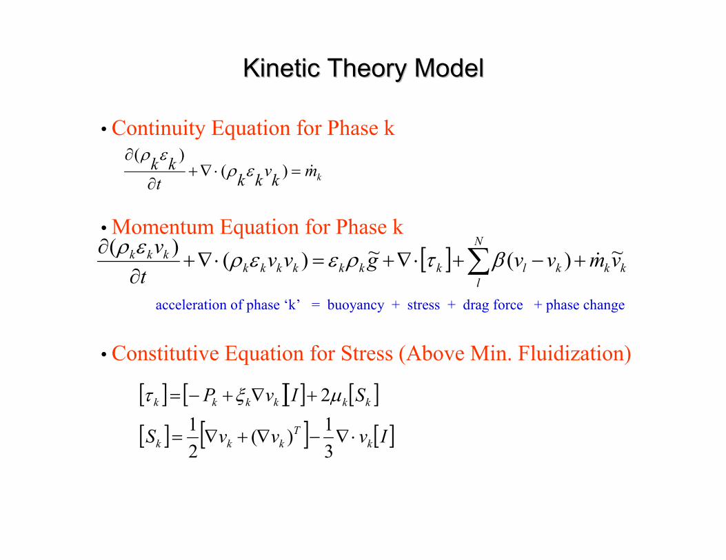
NETL AND PSRI RISERS
Computation of turbulence and dispersion of cork in the NETL rise,
Jiradilok, V., Gidaspow, D., Breault, R.W., Shadle, L.J., Guenther, C.,
Shi, Shaoping, Chem. Eng. Sci. 63 (2008), 2135-2148
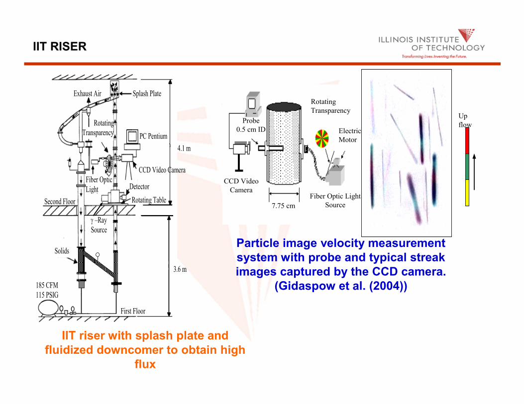
185 CFM
115 PSIG
First Floor
3.6 m
4.1 m
Second Floor
Solids
Exhaust Air Splash Plate
CCD Video Camera
Rotating Table
Detector
γ –Ray
Source
Fiber Optic
Light
Source
Rotating
Transparency
PC Pentium
IIT riser with splash plate and
fluidized downcomer to obtain high
flux
Up flow
Rotating
Transparency
Electric
Motor
Fiber Optic Light
Source
CCD Video
Camera
Probe
0.5 cm ID
Up
flow
7.75 cm
Particle image velocity measurement
system with probe and typical streak
images captured by the CCD camera.
(Gidaspow et al. (2004))
IIT RISER
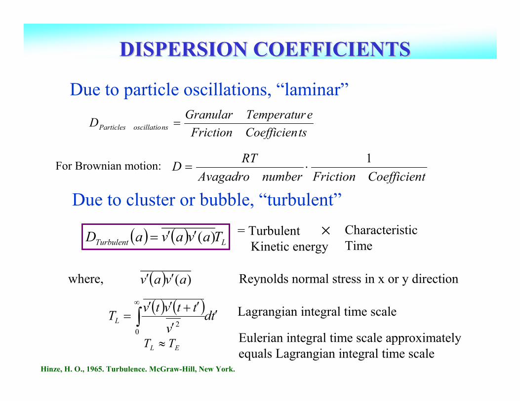
DISPERSION COEFFICIENTSDISPERSION COEFFICIENTS
Due to particle oscillations, “laminar”
( ) ( )td
v
ttvtvTL ′
′
′+′′= ∫
∞
02
( ) ( ) LTurbulent TavavaD )(′′=
where,
Lagrangian integral time scale
( ) )(avav ′′ Reynolds normal stress in x or y direction
Due to cluster or bubble, “turbulent”
= Turbulent
Kinetic energy
Characteristic
Time×
EL TT ≈ Eulerian integral time scale approximately
equals Lagrangian integral time scaleHinze, H. O., 1965. Turbulence. McGraw-Hill, New York.
tsCoefficienFriction
eTemperaturGranularD nsoscillatioParticles =
For Brownian motion:tCoefficienFrictionnumberAvagadro
RTD
1⋅=

Axial Gas Dispersion CoefficientsAxial Gas Dispersion Coefficients

Radial Gas Dispersion CoefficientsRadial Gas Dispersion Coefficients

0.001
0.01
0.1
1
10
100
0.01 0.1 1 10
Gas Velocity (m/sec)
Ax
ial
So
lid
s D
isp
ersi
on
(m2/s
ec)
Du et al. (2002)
Thiel and Potter (1978)Aviden and Yerushalmi (1985)
Wei et al. (1998)Wei et al. (1995)
Gidaspow et al . (2004), IIT RiserNETL unit, 850µm Cork particles
Jiradilok et al . (2006), FCC particles
2 m.
4 m.
6 m.
This study (Bubbling Bed, 500µm)
Experiment
Computation
Bubble
Computation, 1 atm
Single particle
oscillation
Cluster
Computation
NETL ,
Cork particles
Axial Solids Dispersion CoefficientsAxial Solids Dispersion Coefficients

0.001
0.01
0.1
1
0.1 1 10
Gas Velocity (m/sec)
Rad
ial S
olid
s D
isp
ersi
on
(m2/s
ec)
Du et al.(2002)
Koenigdorff and Werther (1995)
Wei et al. (1998)Wei et al. (1995)
Jiradilok et al. (2006), FCC particles
2 m.
4 m.
6 m.
This study (Bubbling Bed, 500µm)
Experiment
Computation
Bubble
Computation, 1
atm
Cluster
Computation
Radial Solids Dispersion CoefficientsRadial Solids Dispersion Coefficients

IIT 2-D FLUIDIZED BED

INSTANTANEOUS VELOCITES
H = 69.85 cm
Ug = 46.67 cm/s
t = 1/250 s
0
500
1000
1500
2000
2500
-30 -20 -10 0 10 20 30 40 50 60 70 80
Axial velocity (cm/s)
Nu
mb
er
of
part
icle
s
0
500
1000
1500
2000
2500
-25 -20 -15 -10 -5 0 5 10 15 20 25 30
Radial velocity (cm/s)
Nu
mb
er
of p
art
icle
s

GRANULAR TEMPERATURE
Comparison of laminar and turbulent granular temperatures
in IIT 2- D circulating fluidized bed and IIT riser
2.54 x 10-36.67 x 10-3Right Wall2-D CFB, 75 µm
FCC particles
2.61 x 10-29.48 x 10-2WallIIT Riser, 1093 µm
2-D CFB, 75 µm
FCC particles
System
Granular Temperature, m2/s2
Center
Radial Position
6.73 x 10-31.27 x 10-2
Turbulent due to
cluster
oscillations
Laminar due to
individual
particle
oscillations
Mixing is on the level of particles
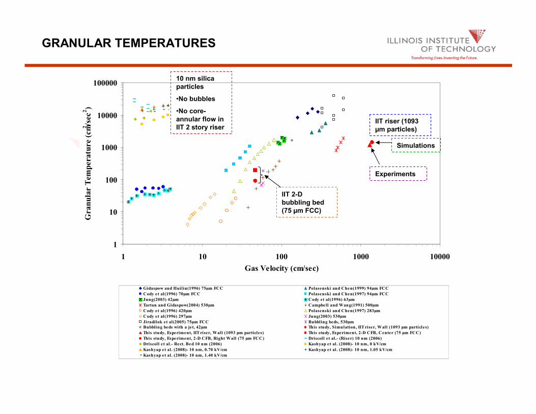
GRANULAR TEMPERATURES
1
10
100
1000
10000
100000
1 10 100 1000 10000
Gas Velocity (cm/sec)
Gran
ula
r T
em
peratu
re (
cm2
/sec
2)
Gidaspow and Huilin(1996) 75µm FCC Polasenski and Chen(1999) 94µm FCC
Cody et al(1996) 70µm FCC Polasenski and Chen(1997) 94µm FCC
Jung(2003) 42µm Cody et al(1996) 63µm
Tartan and Gidaspow(2004) 530µm Campbell and Wang(1991) 500µm
Cody et al(1996) 420µm Polasenski and Chen(1997) 283µm
Cody et al(1996) 297µm Jung(2003) 530µm
Jiradilok et al(2005) 75µm FCC Bubbling beds, 530µm
Bubbling beds with a jet, 42µm This study, Simulation, IIT riser, Wall (1093 µm particles)
This study, Experiment, IIT riser, Wall (1093 µm particles) This study, Experiment, 2-D CFB, Center (75 µm FCC)
This study, Experiment, 2-D CFB, Right Wall (75 µm FCC) Driscoll et al .- (Riser) 10 nm (2006)
Driscoll e t al .- Rect. Bed 10 nm (2006) Kashyap et al . (2008)- 10 nm, 0 kV/cm
Kashyap et al . (2008)- 10 nm, 0.70 kV/cm Kashyap et al . (2008)- 10 nm, 1.05 kV/cm
Kashyap et al . (2008)- 10 nm, 1.40 kV/cm
10 nm silica
particles
•No bubbles
•No core-
annular flow in
IIT 2 story riserIIT riser (1093
µm particles)
Simulations
Experiments
IIT 2-D
bubbling bed
(75 µm FCC)

AXIAL SOLID DISPERSION COEFFICIENTS
0.0001
0.001
0.01
0.1
1
10
100
1000
0.01 0.1 1 10 100
Gas Velocity (m/sec)
Ax
ial
Soli
ds
Dis
persi
on
(m2
/sec)
Fan et al . (2002)
Thiel and Potter (1978)
Aviden and Yerushalmi (1985)
Wei et al. (1998)
Wei et al. (1995)
This study (Simulation, wall); 4.5 m; 14 m/s
This study, IIT riser, 1093 µm
This study, 2-D Bed, Center, 75 µm FCC
This study, 2-D Bed, Right Wall , 75 µm FCC
Experiment (laminar)
Simulations (laminar)
Experiment (turbulent)
Simulations (turbulent)
IIT 2-D
bubbling bed
(75 µm FCC)
IIT riser (1093
µm particles)
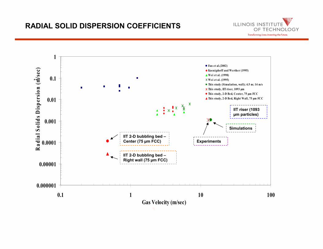
RADIAL SOLID DISPERSION COEFFICIENTS
0.000001
0.00001
0.0001
0.001
0.01
0.1
1
0.1 1 10 100
Gas Velocity (m/sec)
Ra
dia
l S
oli
ds
Dis
per
sio
n (
m2/s
ec) Fan et al .(2002)
Koenigdorff and Werther (1995)
Wei et al. (1998)
Wei et al. (1995)
This study (Simulation, wall); 4.5 m; 14 m/s
This study, IIT riser, 1093 µm
This study, 2-D Bed, Center, 75 µm FCC
This study, 2-D Bed, Right Wall, 75 µm FCC
IIT 2-D bubbling bed –
Center (75 µm FCC)
IIT 2-D bubbling bed –
Right wall (75 µm FCC)
IIT riser (1093
µm particles)
Simulations
Experiments

OZONE DECOMPOSITION REACTION EXPERIMENTAL
SETUP

OZONE CONCENTRATION
0
2
4
6
8
10
12
14
0 0.2 0.4 0.6 0.8 1 1.2
Height (m)
Ozo
ne
co
nc
en
tra
tio
n (
PP
M)
Ug = 28.9 cm/s; H0 =0.054 m
Ug = 33.74 cm/s; H0 = 0.054 m
Ug = 34.34 cm/s; H0 = 0.054 m

Ozone decomposition reaction Ozone decomposition reaction ��������
Conservation of species equation in the code:Conservation of species equation in the code:
A one dimensional approximation leads to:A one dimensional approximation leads to:
where, where, ““KK”” is the overall rate constant given by the additive is the overall rate constant given by the additive
resistance concept asresistance concept as
Sherwood number, Sherwood number,
COMPUTATION OF SHERWOOD NUMBERS AND MASS COMPUTATION OF SHERWOOD NUMBERS AND MASS
TRANSFER COEFFICIENTSTRANSFER COEFFICIENTS
)(2)(3 32 gg OO →
reactionvtransfermass kakK
111+=
D
dkSh
ptransfermass=
sO
O
gy KCdY
dCv εε
3
3 −=
isreactioniigig CkvCCt
εεε =∇+∂∂
).()(

PARTICLE CLUSTER DIAMETERPARTICLE CLUSTER DIAMETER
-40
-35
-30
-25
-20
-15
-10
-5
0
0 2 4 6 8 10 12 14
Riser height (m)
Natu
ral lo
gari
thm
of
tim
e-a
vera
ged
ozo
ne m
ola
r
co
ncen
trati
on
kReaction = 3.96 1/s
kReaction = 39.60 1/s
kReaction = 99.00 1/s
kReaction = 198.00 1/s
Particle cluster diameters (m) Method Height (m)
Minimum Maximum Averaged
This study 3.5 0.0064 0.0232 0.0101
7.0 0.0040 0.0238 0.0095
10.5 0.0027 0.0150 0.0087
Averaged 0.0027a 0.0238
b 0.0095
Harris's correlation 3.5 0.0033 0.0151 0.0092
7.0 0.0035 0.0149 0.0092
10.5 0.0034 0.0165 0.0099
Averaged 0.0033a 0.0165b 0.0095
Gu's correlation 3.5 0.0028 0.0154 0.0091
7.0 0.0030 0.0149 0.0089
10.5 0.0029 0.0175 0.0102
Averaged 0.0028a 0.0175
b 0.0094

For PSRI riser Challenge Problem 1, overall mass transfer coeffiFor PSRI riser Challenge Problem 1, overall mass transfer coefficient, cient, KK = 30.81 s= 30.81 s--11
((Chalermsinsuwan, B., P. Piumsomboon, and D. Gidaspow, “Kinetic theory based computation of PSRI riser- Part II:
Computation of mass transfer coefficient with chemical reaction”, Chemical Engineering Science, 64 (2009) 1212-
1222)
The mass transfer coefficient is calculated from equation:The mass transfer coefficient is calculated from equation:
WithWith ddpp = 76= 76××××××××1010--66 mm
aavv = (3= (3××××××××44ππππππππ((particleparticle radiusradius22)) / (4)) / (4ππππππππ((particleparticle radiusradius33)) ))
= 3/particle radius = 3/particle radius
= 3/(= 3/(ddpp/2)/2)
= 3/((76= 3/((76××××××××1010--66)/2) = 78947.37 m)/2) = 78947.37 m--11
kkreactionreaction = 39.60 s= 39.60 s--11
Note that the overall resistance, 1/Note that the overall resistance, 1/KK, and the reaction resistance, 1/, and the reaction resistance, 1/kkreactionreaction, are close , are close
to each other. This implies that the mass transfer resistance isto each other. This implies that the mass transfer resistance is small.small.
Therefore,Therefore, kkmassmass transfertransfer aavv = 138.71 s= 138.71 s--11 andand
kkmassmass transfertransfer = 0.0018 = 0.0018 m/sm/s
The Sherwood number is calculated from equation:The Sherwood number is calculated from equation:
With With DD = 2.88= 2.88××××××××1010--55 mm22/s/s
Therefore, Therefore, ShSh = 0.0046 = 0.0046
EXAMPLE OF SHERWOOD NUMBER AND EXAMPLE OF SHERWOOD NUMBER AND
MASS TRANSFER COEFFICIENTMASS TRANSFER COEFFICIENT
reactionvtransfermass kakK
111+=
D
dkSh
ptransfermass=
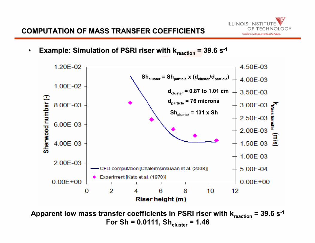
•• Example: Simulation of PSRI riser with Example: Simulation of PSRI riser with kkreactionreaction = 39.6 s= 39.6 s--11
COMPUTATION OF MASS TRANSFER COEFFICIENTS COMPUTATION OF MASS TRANSFER COEFFICIENTS
Apparent low mass transfer coefficients in PSRI riser with kreaction = 39.6 s-1
For Sh = 0.0111, Shcluster = 1.46
Shcluster = Shparticle x (dcluster/dparticle)
dcluster = 0.87 to 1.01 cm
dparticle = 76 microns
Shcluster = 131 x Sh

EFFECTIVE RATE CONSTANT
saveragegg KCdY
dCv εε −=
Differential reactor analysis
Cluster regimekreaction = 14.45 sec-1
K = 3.62 sec-1
kmass transfer = 0.0000611 m/s
Sh (bubbling) = 0.00016
2
)(
2
)(
)(
)( 2121
12
12 ssg
CCK
YY
CCU
εε ++−=
−−
0
2
4
6
8
10
12
14
16
18
0 0.1 0.2 0.3 0.4 0.5 0.6 0.7 0.8
Height (m)
Eff
ec
tiv
e r
ate
co
ns
tan
t (s
ec
-1)
Ug = 33.74 cm/s-Measured
Ug = 34.34 cm/s-Measured
Ug = 33.74 cm/s-Estimated
Ug = 34.34 cm/s-Estimated
Bubbling bed
CONCLUSIONS
We have shown that the kinetic theory based CFD codes correctly
compute:
(1) Dispersion coefficients
(2) Mass transfer coefficients
Hence, the kinetic theory based CFD codes can be used for fluidized
bed reactor design without any such inputs

BACKUP SLIDES
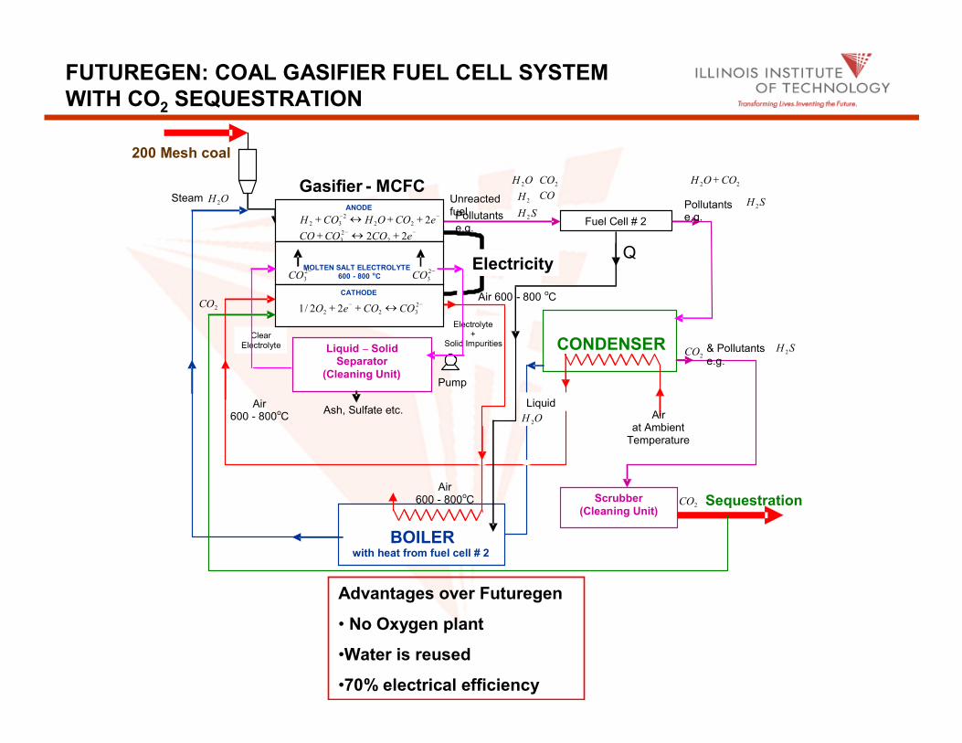
FUTUREGEN: COAL GASIFIER FUEL CELL SYSTEM
WITH CO2 SEQUESTRATION
BOILERwith heat from fuel cell # 2
CONDENSER
Air at Ambient Temperature
Air 600 - 800oC
Air 600 - 800 oC
Ash, Sulfate etc.
2CO
Steam OH 2
200 Mesh coal
Liquid – Solid Separator
(Cleaning Unit)
Electrolyte+
Solid ImpuritiesClear
Electrolyte
Unreactedfuel
2H CO
SH 2Pollutants e.g.
OH 2
Fuel Cell # 2
22 COOH +
SH 2Pollutants e.g.
Scrubber
(Cleaning Unit)
Air 600 - 800
oC
ANODE
MOLTEN SALT ELECTROLYTE
600 - 800 oC
CATHODE
−− ++↔+ eCOOHCOH 222
2
32
−− +↔+ eCOCOCO 22 2
2
3
−− ↔++ 2
322 22/1 COCOeO
−2
3CO−2
3CO
Liquid
OH 2
2CO SH 2& Pollutants
e.g.
2CO Sequestration
Electricity
Gasifier - MCFC
Pump
2CO
Q
Advantages over Futuregen
• No Oxygen plant
•Water is reused
•70% electrical efficiency

FUTUREGEN: IDEAL GASIFIER FUEL CELL WITH
CARBON FEED
Gasifier - MCFC
Electricity
BOILER
ANODE
MOLTEN SALT ELECTROLYTE 600 - 800 oC
CATHODE
−− ++↔+ eCOOHCOH 222
2
32
−− +↔+ eCOCOCO 22 2
2
3
−− ↔++ 2
322 22/1 COCOeO
−2
3CO −2
3CO
22 COOH + CONDENSER
Air at Ambient Temperature
Air 600 - 800 oC
Air 600 - 800 oC
Liquid
2CO
OH 2
Sequestration
Steam OH2
Carbon
2CO