Embed Size (px)
Citation preview
COMPUTATIONAL ANALYSIS OF HIGH SPEED FLOW OVER A CONICAL SURFACE FOR AIR AS WORKING FLUID
Khaled Alhussan Research Assistant Professor, Space Research Institute, King Abdulaziz City for Science & Technology,
Saudi Arabia, P.O. Box 6086, Riyadh 11442, Tel: +9661-481-4508, Fax +9661-481-3845, E-mail:[email protected]
Abstract:- The work to be presented herein is a Computational Fluid Dynamics analysis of flow over a 20-degree half angle cone for a compressible air, with Mach number of 3.0. The problem to be solved involves formation of shock waves so that the general characteristics of supersonic flow are explored through this problem. Shock waves and slip surfaces are discontinuities in fluid mechanics problems. It is essential to evaluate the ability of numerical technique that can solve problems in which shocks and contact surfaces occur. In particular it is necessary to understand the details of developing a mesh that will allow resolution of these discontinuities.
Results including contour plots of pressure, temperature, density and Mach number will show that CFD is capable of predicting accurate results and is also able to capture the discontinuities in the flow, e.g., the oblique shock waves. The global comparison between the numerical and the analytical values show a good agreement. Key- Words: Three Dimensional Oblique Shock Waves, High Speed Flow, Numerical Analysis, CFD.
INTRODUCTION
This paper will explain the numerical analysis and the structure of the flow over a two dimensional 20-degree half angle cone. In this paper some characteristics of compressible, flow are explored, including compression and expansion waves. The work to be presented herein is a Computational Fluid Dynamics investigation of the complex fluid phenomena that occur inside three-dimensional region, specifically with regard to the structure of oblique shock waves around the a cone. Solving this problems one can compare solutions from the CFD with analytical solutions.[1]
The problems to be solved involve formation of three dimensional oblique shock waves, so that the general characteristics of supersonic flow are explored through this paper. Shock waves and slip surfaces are discontinuities in fluid dynamics problems, It is essential to evaluate the ability of numerical technique that can solve problems in which shocks and contact surfaces occur. In particular it is necessary to understand the details of developing a mesh that will allow resolution of these discontinuities [1].
Continuous compression waves always converge and the waves may coalesce and form a shock front. As
more and more of the compression waves coalesce, the wave steepens and becomes more shock fronted. Discontinuities exist in the properties of the fluid as it flows through the shock wave, which may be treated as boundary for the continuous flow regions located on each side of it. Shock waves are also formed when the velocity of the fluid at the solid boundary of the flow field is discontinuous, as in the instantaneous acceleration of a piston. A moving shock wave may be transformed into a stationary shock wave by a relative coordinate transformation wherein the observer moves at the same velocity as the shock wave. The resulting stationary shock wave may, therefore, be analyzed as a steady state case [2-14].
In addition to the shock wave, there is another type of discontinuity termed a contact surface. The contact surface is an interface that separates two flow regions, but moves with those regions. The velocity and the pressure of the gas on each side of the contact surface are the same, but the other thermodynamic properties may be different. Unlike the shock wave, there is no flow of gas across a contact surface. It is clear that nothing is learned about the possibility of the formation of a contact surface from the velocity and pressure,
Proceedings of the 3rd IASME/WSEAS Int. Conf. on FLUID DYNAMICS & AERODYNAMICS, Corfu, Greece, August 20-22, 2005 (pp202-205)
because velocity and pressure are equal across the contact surface [4-13].
CFX is used in this current research to model the flow characteristics over the cone. CFX solves the three-dimensional Navier-Stokes equations by utilizing a finite element based finite volume method over structured hexahedral grids. The CFD code is an integrated software system capable of solving diverse and complex multidimensional fluid flow problems. The fluid flow solver provides solutions for incompressible or compressible, steady-state or transient, laminar or turbulent single-phase fluid flow in complex geometries. The code system has additional capabilities that can predict subsonic, transonic and supersonic compressible flows, including temperature solutions in solid regions of the domain for laminar or turbulent flow. The code uses block-structured, non-orthogonal grids with grid embedding and grid attaching to discretize the domain.
It should be possible to model the formation of the shock waves and expansion fans around the cone using the CFD analysis. The governing equations are a set of coupled nonlinear, partial differential equations. In order to formulate or approximate a valid solution for these equations they must be solved using computational fluid dynamics techniques. To solve the equations numerically they must be discretized. That is, the continuous control volume equations must be applied to each discrete control volume that is formed by the computational grid. The integral equations are replaced with a set of linear algebraic equations solved at a discrete set of points.
In a finite element discretization the grid breaks up the domain into elements over which the changes of the fluid variables are evaluated. Adding all the variations for each element then gives an overall visualization of how the variables vary over the entire domain. The primary advantage of the finite element method is the geometric flexibility allowed by a finite element grid. In a finite volume discretization the grid breaks up the domain into nodes, each associated with a discrete control volume. The flux of mass, momentum, and energy for each control volume is then calculated at each node. An advantage of the finite volume method is that the principles of mass, momentum, and energy conservation are applied directly to each control volume, so that the integral conservation of quantities is exactly satisfied for any set of control volumes in the domain. Thus, even for a coarse grid, there is an exact integral flux balance.
A numerical analysis must start with breaking the computational domain into discrete sub-domains, which is the grid generation process. A grid must be provided in terms of the spatial coordinates of grid nodes distributed throughout the computational domain. At each node in the domain, the numerical analysis will
determine values for all dependent variables such as pressure and velocity components. Creating the grid is the first step in calculating a flow. Solution parameters and fluid properties are defined in the parameter file. The advection discretization scheme selected is the Modified Linear Profile Skew scheme with the Physical Correction. The convergence criterion is 10E-04 and the solver is left to run until a converged solution is found [15-22]. DISCUSSION AND RESULTS
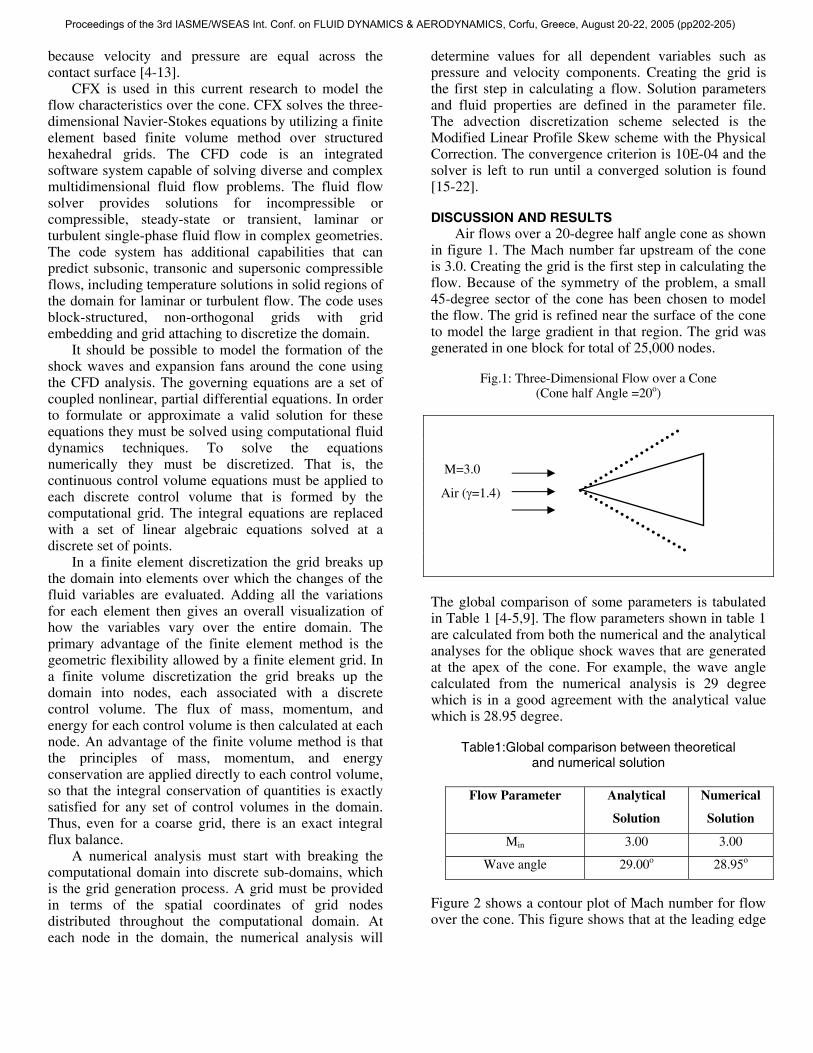
Air flows over a 20-degree half angle cone as shown in figure 1. The Mach number far upstream of the cone is 3.0. Creating the grid is the first step in calculating the flow. Because of the symmetry of the problem, a small 45-degree sector of the cone has been chosen to model the flow. The grid is refined near the surface of the cone to model the large gradient in that region. The grid was generated in one block for total of 25,000 nodes.
Fig.1: Three-Dimensional Flow over a Cone (Cone half Angle =20o)
M=3.0
Air (γ=1.4)
The global comparison of some parameters is tabulated in Table 1 [4-5,9]. The flow parameters shown in table 1 are calculated from both the numerical and the analytical analyses for the oblique shock waves that are generated at the apex of the cone. For example, the wave angle calculated from the numerical analysis is 29 degree which is in a good agreement with the analytical value which is 28.95 degree.
Table1:Global comparison between theoretical
and numerical solution
Figure 2 shows a contour plot of Mach number for flow over the cone. This figure shows that at the leading edge
Flow Parameter Analytical
Solution
Numerical
Solution
Min 3.00 3.00
Wave angle 29.00o 28.95o
Proceedings of the 3rd IASME/WSEAS Int. Conf. on FLUID DYNAMICS & AERODYNAMICS, Corfu, Greece, August 20-22, 2005 (pp202-205)
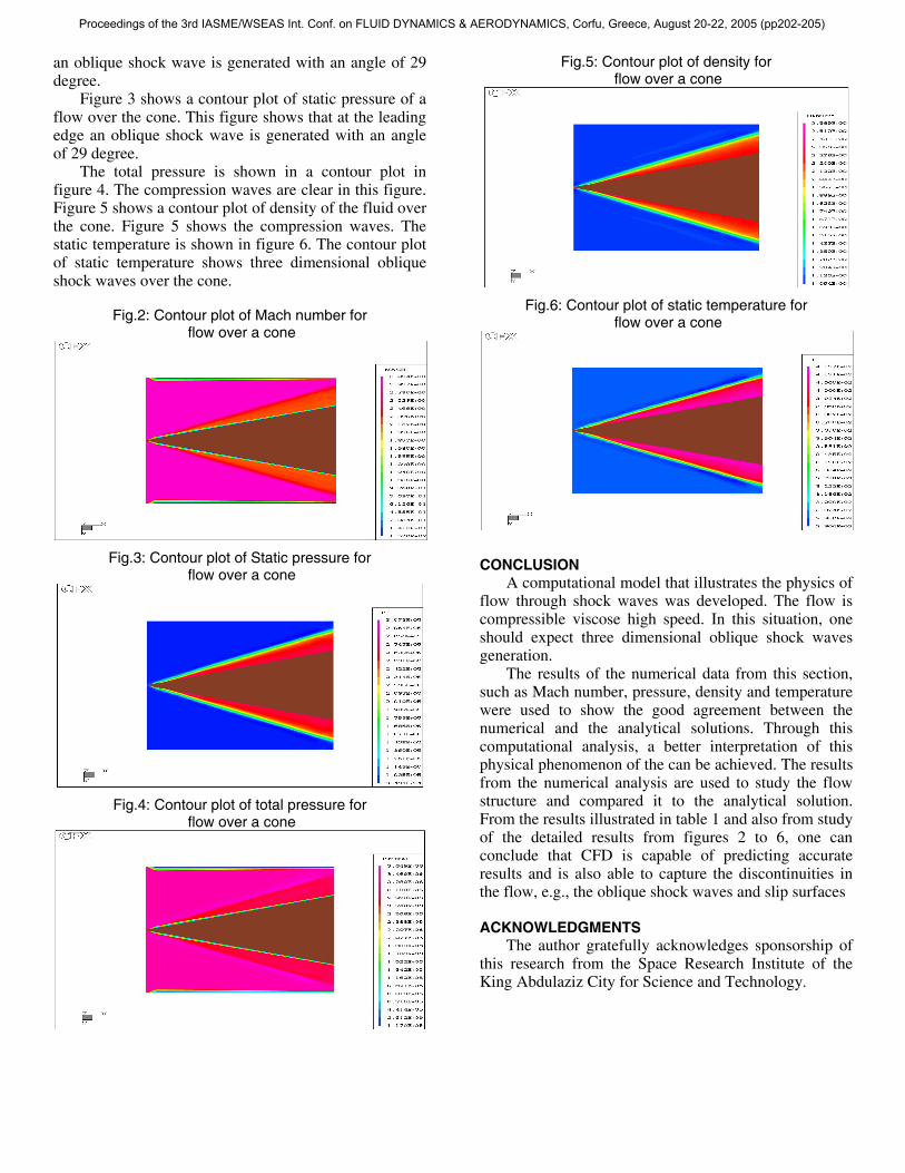
an oblique shock wave is generated with an angle of 29 degree.
Figure 3 shows a contour plot of static pressure of a flow over the cone. This figure shows that at the leading edge an oblique shock wave is generated with an angle of 29 degree.
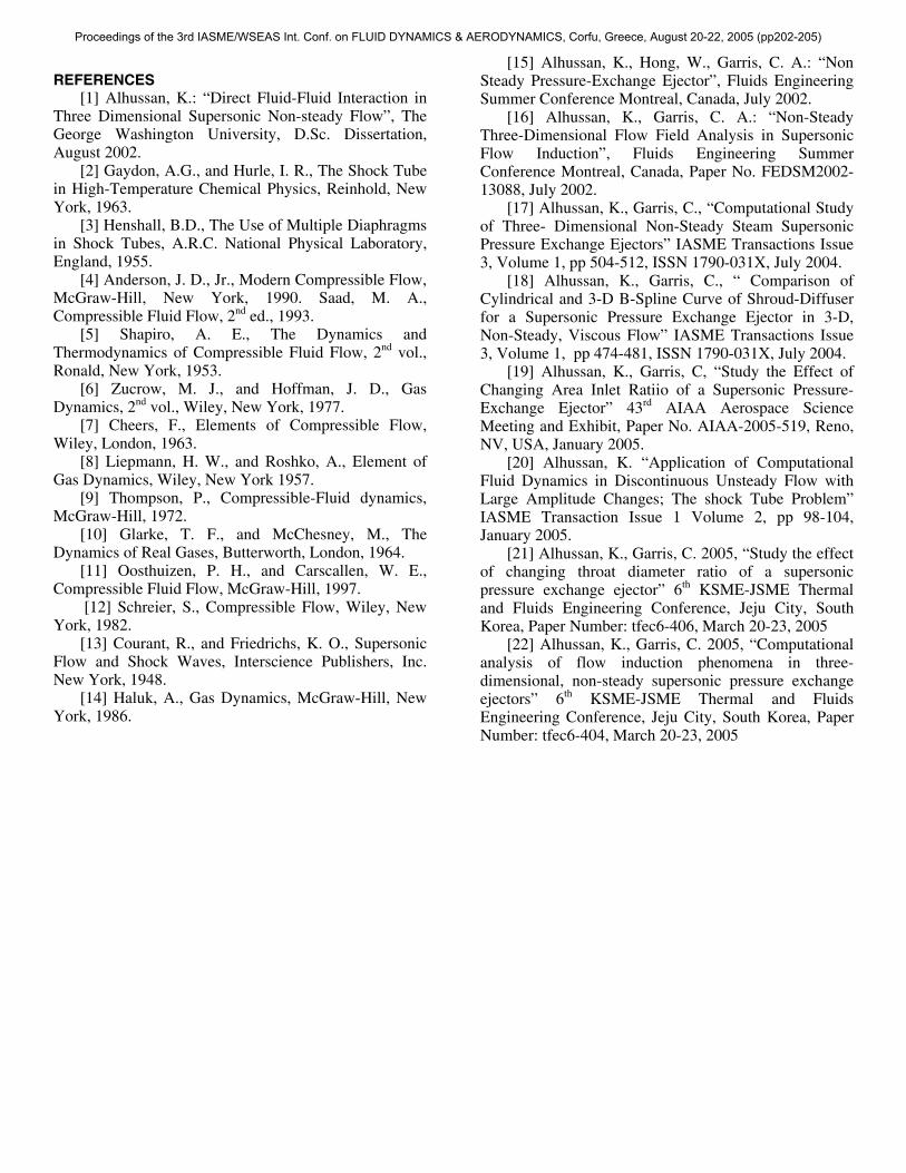
The total pressure is shown in a contour plot in figure 4. The compression waves are clear in this figure. Figure 5 shows a contour plot of density of the fluid over the cone. Figure 5 shows the compression waves. The static temperature is shown in figure 6. The contour plot of static temperature shows three dimensional oblique shock waves over the cone.
Fig.2: Contour plot of Mach number for
flow over a cone
Fig.3: Contour plot of Static pressure for flow over a cone
Fig.4: Contour plot of total pressure for flow over a cone
Fig.5: Contour plot of density for flow over a cone
Fig.6: Contour plot of static temperature for flow over a cone
CONCLUSION
A computational model that illustrates the physics of flow through shock waves was developed. The flow is compressible viscose high speed. In this situation, one should expect three dimensional oblique shock waves generation.
The results of the numerical data from this section, such as Mach number, pressure, density and temperature were used to show the good agreement between the numerical and the analytical solutions. Through this computational analysis, a better interpretation of this physical phenomenon of the can be achieved. The results from the numerical analysis are used to study the flow structure and compared it to the analytical solution. From the results illustrated in table 1 and also from study of the detailed results from figures 2 to 6, one can conclude that CFD is capable of predicting accurate results and is also able to capture the discontinuities in the flow, e.g., the oblique shock waves and slip surfaces
ACKNOWLEDGMENTS The author gratefully acknowledges sponsorship of
this research from the Space Research Institute of the King Abdulaziz City for Science and Technology.
Proceedings of the 3rd IASME/WSEAS Int. Conf. on FLUID DYNAMICS & AERODYNAMICS, Corfu, Greece, August 20-22, 2005 (pp202-205)
REFERENCES [1] Alhussan, K.: “Direct Fluid-Fluid Interaction in
Three Dimensional Supersonic Non-steady Flow”, The George Washington University, D.Sc. Dissertation, August 2002.
[2] Gaydon, A.G., and Hurle, I. R., The Shock Tube in High-Temperature Chemical Physics, Reinhold, New York, 1963.
[3] Henshall, B.D., The Use of Multiple Diaphragms in Shock Tubes, A.R.C. National Physical Laboratory, England, 1955.
[4] Anderson, J. D., Jr., Modern Compressible Flow, McGraw-Hill, New York, 1990. Saad, M. A., Compressible Fluid Flow, 2nd ed., 1993.
[5] Shapiro, A. E., The Dynamics and Thermodynamics of Compressible Fluid Flow, 2nd vol., Ronald, New York, 1953.
[6] Zucrow, M. J., and Hoffman, J. D., Gas Dynamics, 2nd vol., Wiley, New York, 1977.
[7] Cheers, F., Elements of Compressible Flow, Wiley, London, 1963.
[8] Liepmann, H. W., and Roshko, A., Element of Gas Dynamics, Wiley, New York 1957.
[9] Thompson, P., Compressible-Fluid dynamics, McGraw-Hill, 1972.
[10] Glarke, T. F., and McChesney, M., The Dynamics of Real Gases, Butterworth, London, 1964.
[11] Oosthuizen, P. H., and Carscallen, W. E., Compressible Fluid Flow, McGraw-Hill, 1997.
[12] Schreier, S., Compressible Flow, Wiley, New York, 1982.
[13] Courant, R., and Friedrichs, K. O., Supersonic Flow and Shock Waves, Interscience Publishers, Inc. New York, 1948.
[14] Haluk, A., Gas Dynamics, McGraw-Hill, New York, 1986.
[15] Alhussan, K., Hong, W., Garris, C. A.: “Non Steady Pressure-Exchange Ejector”, Fluids Engineering Summer Conference Montreal, Canada, July 2002.
[16] Alhussan, K., Garris, C. A.: “Non-Steady Three-Dimensional Flow Field Analysis in Supersonic Flow Induction”, Fluids Engineering Summer Conference Montreal, Canada, Paper No. FEDSM2002-13088, July 2002.
[17] Alhussan, K., Garris, C., “Computational Study of Three- Dimensional Non-Steady Steam Supersonic Pressure Exchange Ejectors” IASME Transactions Issue 3, Volume 1, pp 504-512, ISSN 1790-031X, July 2004.
[18] Alhussan, K., Garris, C., “ Comparison of Cylindrical and 3-D B-Spline Curve of Shroud-Diffuser for a Supersonic Pressure Exchange Ejector in 3-D, Non-Steady, Viscous Flow” IASME Transactions Issue 3, Volume 1, pp 474-481, ISSN 1790-031X, July 2004.
[19] Alhussan, K., Garris, C, “Study the Effect of Changing Area Inlet Ratiio of a Supersonic Pressure-Exchange Ejector” 43rd AIAA Aerospace Science Meeting and Exhibit, Paper No. AIAA-2005-519, Reno, NV, USA, January 2005.
[20] Alhussan, K. “Application of Computational Fluid Dynamics in Discontinuous Unsteady Flow with Large Amplitude Changes; The shock Tube Problem” IASME Transaction Issue 1 Volume 2, pp 98-104, January 2005.
[21] Alhussan, K., Garris, C. 2005, “Study the effect of changing throat diameter ratio of a supersonic pressure exchange ejector” 6th KSME-JSME Thermal and Fluids Engineering Conference, Jeju City, South Korea, Paper Number: tfec6-406, March 20-23, 2005
[22] Alhussan, K., Garris, C. 2005, “Computational analysis of flow induction phenomena in three-dimensional, non-steady supersonic pressure exchange ejectors” 6th KSME-JSME Thermal and Fluids Engineering Conference, Jeju City, South Korea, Paper Number: tfec6-404, March 20-23, 2005
Proceedings of the 3rd IASME/WSEAS Int. Conf. on FLUID DYNAMICS & AERODYNAMICS, Corfu, Greece, August 20-22, 2005 (pp202-205)