Embed Size (px)
Citation preview
Journal of KONES Powertrain and Transport, Vol. 23, No. 1 2016
COMPUTATIONAL MODEL OF HIGH ALTITUDE AIRCRAFT AERODYNAMICS
Wiesław Zalewski
Institute of Aviation Krakowska Avenue 110/114, 02-256
tel.:+48 22 8460011, fax: +48 22 8464432 e-mail: [email protected]
Abstract
The paper presents computational fluid dynamics hybrid model for analysis of complex flow composed of flow zones at low Reynolds number and flow zones at relatively high Reynolds number conditions. In the described model both ranges of the flow are separated and resolved independently using different way of simulation. That kind of phenomenon is typical for aerodynamics of unmanned propeller driven aircrafts operating at very high altitude conditions (stratospheric). That type of aerial vehicles is now used for military and scientific purposes. In many cases, the wings of a plane are operating at relatively high Reynolds number flow conditions and low angles of attack while the parts of the propeller blades are working at low Reynolds number flow condition and high angles of attack. Described numerical model was used for analysis of the impact of working propellers on the aerodynamics of the aircraft. Analysis was made on the example of a twin-engine, unmanned aircraft with electric motors during the high altitude flight. Three configurations were studied and compared: the plane without propellers, the plane with pusher propellers and the plane with tractor propellers. For each configuration, distributions of aerodynamic coefficients along the span of the wing and their global values for the entire aircraft were estimated. Calculations were performed using the Fluent solver with implementation of a model of propeller based on the Blade Element Theory. Results of the analysis indicate a slight advantage of the tractor propellers configuration.
Keywords: transport, air transport, simulation, propeller-driven unmanned airplane, propeller-wing interaction, low Reynolds number flows
1. Introduction
In recent years, we have seen a growing interest in the field of unmanned high altitude lightaircrafts powered with electric motors, which are able to operate at range of altitudes up to 20000 m. That kind of aerial vehicles have the possibility to use solar energy as a primary power source. Accumulators, solar cells and hydrogen fuels cells [6] allow them to conduct long time flight without landing and support from the ground. Such features allow the practical use of that kind of aerial vehicles in areas like telecommunication and monitoring both in military and civil applications. Drones are currently the most rapidly growing field of aviation. Effective use and technical problems connected with that technology in military and civil application was the subject of much scientific analysis [1, 3]. Changes in the properties of the atmosphere with altitude make the conditions of flow around airplane wing and propeller blades vary in different phases of flight. This is connected primarily with the change in air density, which decreases about 10 times, from the value of 1.225 kg/m3 at ground surface to 0.088 kg/m3 at an altitude of 20000 m.
Changing of the flow pattern to laminar or turbulent around airfoil is characterized by the Reynolds number (Re), which is dimensionless quantity that measures the ratio of inertial forces to viscous forces and describes the degree of laminar or turbulent flow. Airfoils that operate at the same Reynolds number should have the same flow pattern even if the fluid, speed and characteristic lengths vary. Flow around airfoil at low Reynolds numbers is connected with the risk of occurrence of laminar separation phenomenon. That phenomenon has a destructive effect on the aerodynamic properties of the airfoils and thus on the performance of a wing and
ISSN: 1231-4005 e-ISSN: 2354-0133 DOI: 10.5604/12314005.1213720
W. Zalewski
a propeller. For the airfoils, the influence of the phenomenon of laminar separation begins to be particularly important at the Reynolds number below 100000. In the case of high altitude unmanned aircraft, wing airfoils work usually above that value of the Reynolds number in the whole range of the altitude, while the airfoils of the propeller blades work at the Reynolds number above 100000 for small altitudes and under 100000 for the high altitude. For airfoils of the propeller blades, the flow characteristic is more complicated because we can find a flow at low Reynolds number connected with relatively high Mach number up to 0.6, which are quite atypical conditions in global aviation aerodynamics. It forces, that the compressibility effect should be taken into account during calculation. Such conditions of the flow around the airfoil is now little studied experimentally in meaning of wind tunnel tests and it still creates numerical computational difficulties. Due to the change of condition of the flow around airfoils used in the design of the propeller blades and airplane wing, proper selection of airfoils becomes a serious challenge. Classical airfoils designed for operating at high Reynolds number ranges are exposed to dramatic deterioration of their aerodynamic performance if they are used at low Reynolds numbers conditions.
2. Research model
When operating in the low Reynolds numbers, under 100000, the use of airfoils designed for
such conditions is recommended. These airfoils are designed to avoid and weaken the effect of laminar separation at high angles of attack and its impact on the deterioration of their aerodynamic characteristics. Unfortunately, this type of airfoils has a weaker aerodynamic performance in the range of higher Reynolds numbers. In practice, airfoils used in high altitude aircraft, due to the variability of flight conditions can operate in mixed ranges of Reynolds number over and below 100000. That is especially common for airfoils used in propeller blades. It presents a big challenge for the designer and a decision which type of airfoils should be used should be preceded by analysis connected with numerical optimization process. In that type of analysis advanced, optimization methods such as genetic algorithms are being applied. Optimization methods can be used during the design process of airfoils dedicated for a wing or propeller blades or the entire aerodynamic shape of the aircraft [7-9]. Most of advanced commercial computational solvers based on the finite volume method and averaged Navier-Stokes equations with turbulence model of SST type, produce relatively accurate solutions only for small angles of attack at low Reynolds numbers flow conditions. These methods can be efficiently used for calculating flow around an airplane wing at horizontal flight conditions. In the case of propeller airfoils, such assumption is not correct, due to the much greater range of angles of attack used, especially in constant pitch propellers, which are very popular in unmanned aerial vehicles. Therefore, the calculation of aerodynamic performance of propeller airfoils need to use other methods of calculation, which cope better with the characteristics of flow at low Reynolds numbers and high angles of attack.
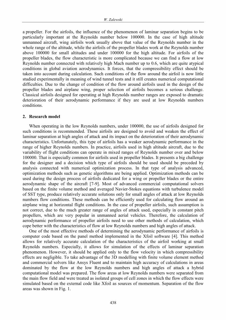
One of the most effective methods of determining the aerodynamic performance of airfoils is computer code based on the panel method implemented in the Xfoil software [4]. This method allows for relatively accurate calculation of the characteristics of the airfoil working at small Reynolds numbers. Especially, it allows for simulation of the effects of laminar separation phenomenon. However, it should be applied only to the flow velocity in which compressibility effects are negligible. To take advantage of the 3D modelling with finite volume element method and commercial solvers like Ansys Fluent and to maintain high accuracy of calculations in areas dominated by the flow at the low Reynolds numbers and high angles of attack a hybrid computational model was prepared. The flow areas at low Reynolds numbers were separated from the main flow field and were treated as isolated groups of cell zones in which the flow effects were simulated based on the external code like Xfoil as sources of momentum. Separation of the flow areas was shown in Fig. 1.
438
Computational Model of High Altitude Aircraft Aerodynamics
Fig. 1. A cross-section through the fluid mesh with a wing and separated cell zone
Such kind of approach enables effective combination of two computational methods focused
on different phenomena. In the paper was presented an example of use of such modelling in the problem of estimating aerodynamic characteristic of high altitude unmanned aircraft which operates at an altitude of 18000 m. Flow around the wings and fuselage of the airplane was modelled using the finite volume method and Navier-Stokes equations. Flow around the propeller blades, which takes place at low Reynolds numbers, was addressed in a separate zone of computational cells. Only the effects of flow generated by the propellers were transferred to the main model. Presented hybrid computational model was used to simulate the effect of propeller-wing interaction for twin-engine plane. The phenomenon of propeller-wing interaction was the subject of many scientific studies [2, 5]. The results of numerical simulations were presented below. 3. Model of the aerial vehicle
An assumption about opposite directions of rotation for left and right propeller was made. That
allows simplifying the model to symmetrical in relation to the vertical plane in the longitudinal axis of the airplane. The right part of the plane, looking in the direction of flight, was modelled. The hybrid computational mesh with about 7 million of elements was prepared for each configuration. The mesh contains prism elements (boundary layer), hexa elements (rotor disk) and tetra elements in fluid zone.
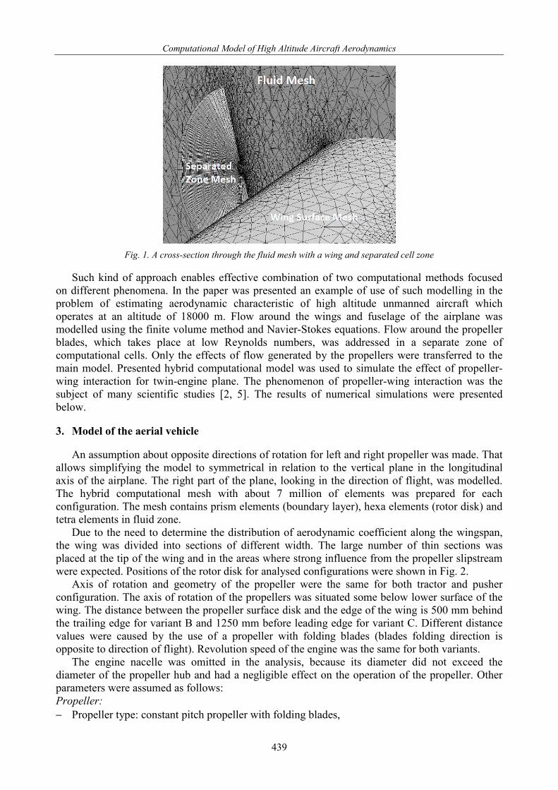
Due to the need to determine the distribution of aerodynamic coefficient along the wingspan, the wing was divided into sections of different width. The large number of thin sections was placed at the tip of the wing and in the areas where strong influence from the propeller slipstream were expected. Positions of the rotor disk for analysed configurations were shown in Fig. 2.
Axis of rotation and geometry of the propeller were the same for both tractor and pusher configuration. The axis of rotation of the propellers was situated some below lower surface of the wing. The distance between the propeller surface disk and the edge of the wing is 500 mm behind the trailing edge for variant B and 1250 mm before leading edge for variant C. Different distance values were caused by the use of a propeller with folding blades (blades folding direction is opposite to direction of flight). Revolution speed of the engine was the same for both variants.
The engine nacelle was omitted in the analysis, because its diameter did not exceed the diameter of the propeller hub and had a negligible effect on the operation of the propeller. Other parameters were assumed as follows: Propeller: − Propeller type: constant pitch propeller with folding blades,
439
W. Zalewski
− Airfoil: S2046, diameter: D = 2 m, number of blades: N = 2, − Direction of rotation: clockwise as viewed from the rear in the flight direction on the right side
of the aircraft; Motor: − Power of the motor: P = 2252 W, revolution speed: n = 1487 rpm; Wing: − Semi-span: S = 20 m, airfoil: E387; chord: C = 1.5 m; Flight conditions: − Flight altitude: H = 18000 m, flight speed: V = 33 m/s, − Horizontal flight, constant speed, angle of attack ALFA=0.
Fig. 2. The view of the right half of the airplane with segments pattern on the wing surface; pusher configuration on
the left figure (variant B), tractor configuration on the right figure (variant C) 4. Results of simulation at cruising condition
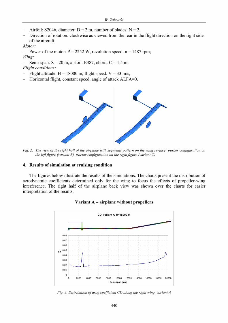
The figures below illustrate the results of the simulations. The charts present the distribution of
aerodynamic coefficients determined only for the wing to focus the effects of propeller-wing interference. The right half of the airplane back view was shown over the charts for easier interpretation of the results.
Variant A – airplane without propellers
CD, variant A, H=18000 m
0
0.01
0.02
0.03
0.04
0.05
0.06
0.07
0.08
0 2000 4000 6000 8000 10000 12000 14000 16000 18000 20000Semi-span [mm]
CD
Fig. 3. Distribution of drag coefficient CD along the right wing, variant A
440
Computational Model of High Altitude Aircraft Aerodynamics
CL, variant A, H=18000 m
0.2
0.4
0.6
0.8
1
1.2
1.4
0 2000 4000 6000 8000 10000 12000 14000 16000 18000 20000Semi-span [mm]
CL
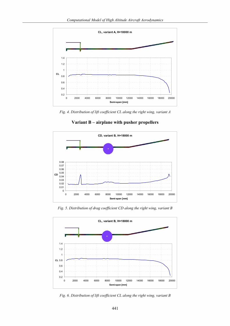
Fig. 4. Distribution of lift coefficient CL along the right wing, variant A
Variant B – airplane with pusher propellers
CD, variant B, H=18000 m
00.010.020.030.040.050.060.070.08
0 2000 4000 6000 8000 10000 12000 14000 16000 18000 20000
Semi-span [mm]
CD
Fig. 5. Distribution of drag coefficient CD along the right wing, variant B
CL, variant B, H=18000 m
0.2
0.4
0.6
0.8
1
1.2
1.4
0 2000 4000 6000 8000 10000 12000 14000 16000 18000 20000Semi-span [mm]
CL
Fig. 6. Distribution of lift coefficient CL along the right wing, variant B
441
W. Zalewski
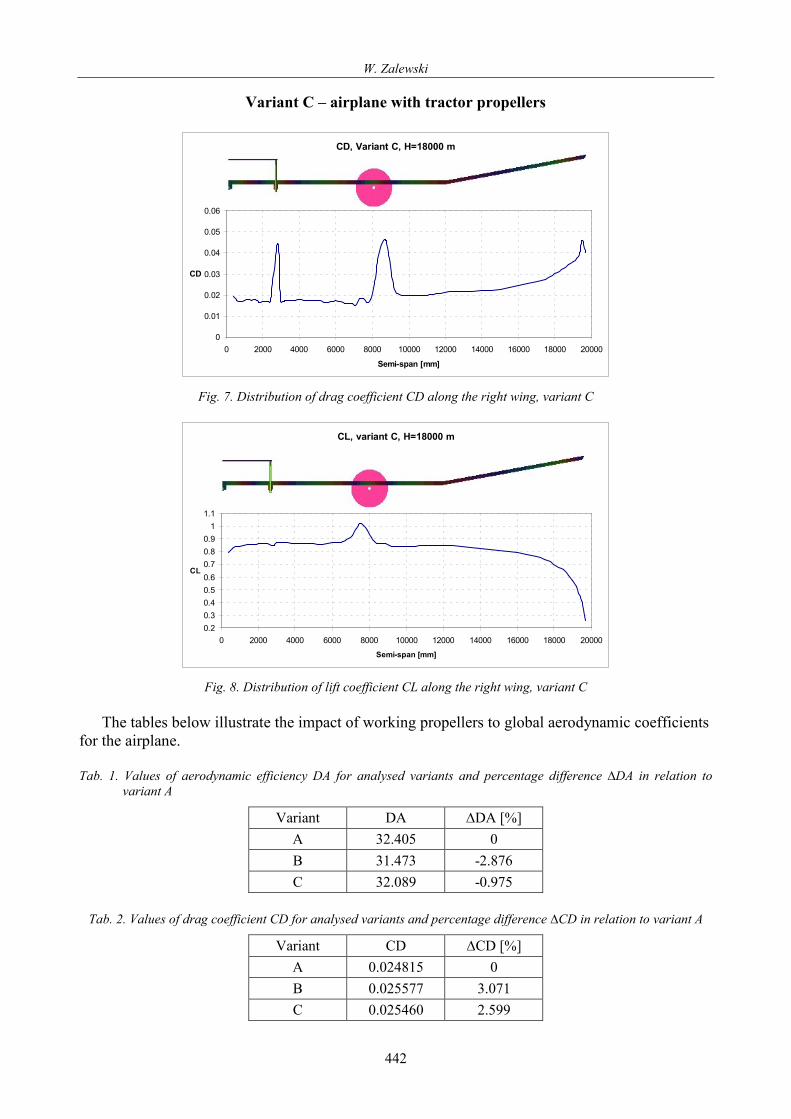
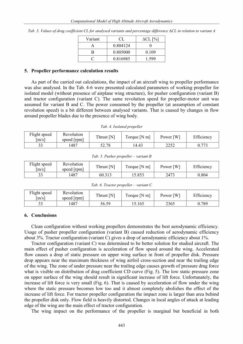
Variant C – airplane with tractor propellers
CD, Variant C, H=18000 m
0
0.01
0.02
0.03
0.04
0.05
0.06
0 2000 4000 6000 8000 10000 12000 14000 16000 18000 20000
Semi-span [mm]
CD
Fig. 7. Distribution of drag coefficient CD along the right wing, variant C
CL, variant C, H=18000 m
0.20.30.40.50.60.70.80.9
11.1
0 2000 4000 6000 8000 10000 12000 14000 16000 18000 20000Semi-span [mm]
CL
Fig. 8. Distribution of lift coefficient CL along the right wing, variant C
The tables below illustrate the impact of working propellers to global aerodynamic coefficients
for the airplane. Tab. 1. Values of aerodynamic efficiency DA for analysed variants and percentage difference ∆DA in relation to
variant A
Variant DA ∆DA [%] A 32.405 0 B 31.473 -2.876 C 32.089 -0.975
Tab. 2. Values of drag coefficient CD for analysed variants and percentage difference ∆CD in relation to variant A
Variant CD ∆CD [%] A 0.024815 0 B 0.025577 3.071 C 0.025460 2.599
442
Computational Model of High Altitude Aircraft Aerodynamics
Tab. 3. Values of drag coefficient CL for analysed variants and percentage difference ∆CL in relation to variant A
Variant CL ∆CL [%] A 0.804124 0 B 0.805000 0.109 C 0.816985 1.599
5. Propeller performance calculation results
As part of the carried out calculations, the impact of an aircraft wing to propeller performance
was also analysed. In the Tab. 4-6 were presented calculated parameters of working propeller for isolated model (without presence of airplane wing structure), for pusher configuration (variant B) and tractor configuration (variant C). The same revolution speed for propeller-motor unit was assumed for variant B and C. The power consumed by the propeller (at assumption of constant revolution speed) is a bit different between analysed variants. That is caused by changes in flow around propeller blades due to the presence of wing body.
Tab. 4. Isolated propeller
Flight speed [m/s]
Revolution speed [rpm] Thrust [N] Torque [N m] Power [W] Efficiency
33 1487 52.78 14.43 2252 0.773
Tab. 5. Pusher propeller – variant B
Flight speed [m/s]
Revolution speed [rpm] Thrust [N] Torque [N m] Power [W] Efficiency
33 1487 60.313 15.853 2473 0.804
Tab. 6. Tractor propeller – variant C
Flight speed [m/s]
Revolution speed [rpm] Thrust [N] Torque [N m] Power [W] Efficiency
33 1487 56.59 15.165 2365 0.789 6. Conclusions
Clean configuration without working propellers demonstrates the best aerodynamic efficiency.
Usage of pusher propeller configuration (variant B) caused reduction of aerodynamic efficiency about 3%. Tractor configuration (variant C) gives a drop of aerodynamic efficiency about 1%.
Tractor configuration (variant C) was determined to be better solution for studied aircraft. The main effect of pusher configuration is acceleration of flow speed around the wing. Accelerated flow causes a drop of static pressure on upper wing surface in front of propeller disk. Pressure drop appears near the maximum thickness of wing airfoil cross-section and near the trailing edge of the wing. The zone of under pressure near the trailing edge causes growth of pressure drag force what is visible on distribution of drag coefficient CD curve (Fig. 5). The low static pressure zone on upper surface of the wing should result in significant increase of lift force. Unfortunately, the increase of lift force is very small (Fig. 6). That is caused by acceleration of flow under the wing where the static pressure becomes low too and it almost completely abolishes the effect of the increase of lift force. For tractor propeller configuration the impact zone is larger than area behind the propeller disk only. Flow field is heavily distorted. Changes in local angles of attack at leading edge of the wing are the main effect of tractor configuration.
The wing impact on the performance of the propeller is marginal but beneficial in both
443
W. Zalewski
configurations. The improvement in propeller efficiency is about 1-3 %. In the case of pusher configuration that is caused by flow around wing airfoils. Airfoil E387 directs the flow down at trailing edge area and changes the local angles of attack for propeller blades (that can be beneficial for constant pitch propeller). For tractor configuration, the wing prevents rotation of the propeller slipstream. Additionally the propeller works in undisturbed flow field. The main advantage of tractor configuration results from less negative impact on the aerodynamics of the wing, what was presented in the Tab. 1. It should also be noted that the results are in strong relation to the specificity of the tested aircraft (small flight speed, applied airfoils, constant pitch propellers, and low power electric motors). References [1] Adamski, M., Modelowanie i badania procesu sterowania bezzałogowymi statkami
powietrznymi, Wydawnictwo Naukowe Instytutu Technologii Eksploatacji PIB, Radom 2016. [2] Catalano, F. M., On the Effects of an Installed Propeller Slipstream on Wing Aerodynamic
Characteristics, Acta Polytechnica, Vol. 44, No. 3, 2004 [3] Cichocka, E., Wyzwania i problemy w budowie stratosferycznych samolotów solarnych, Prace
Instytutu Lotnictwa 221, Warszawa 2011. [4] Drela, M., XFOIL: An Analysis and Design System for Low Reynolds Number Airfoils, MIT
Dept. of Aeronautics and Astronautics, Cambridge, Massachusetts 1990. [5] Gavin, K., Ananda, G. K., Deters, R.W., Selig, M. S., Propeller Induced Flow Effects on
Wings at Low Reynolds Numbers, Fluid Dynamics and Co-located Conferences, 24-27 June, CA, 31st AIAA Applied Aerodynamics Conference, San Diego 2013.
[6] Jankowski, A., Wybrane zagadnienia funkcjonalne i aplikacyjne ogniw paliwowych, Instytut Techniczny Wojsk Lotniczych, 2012.
[7] Stalewski, W., Aerodynamic optymisation of joined-wing aeroplane, 6th Int. Conference on Experiments/Process/System Modelling/Simulation/Optimization 6th IC-EpsMsO, Athens 2015.
[8] Stalewski, W., Numeryczna optymalizacja profili śmigłowcowych oparta na algorytmie genetycznym z uwzględnieniem kryteriów bazujących na niestacjonarnych charakterystykach aerodynamicznych, Prace Instytutu Lotnictwa, Nr 1-2, Warszawa 2006.
[9] Stalewski, W., Parametric Modelling of Aerodynamic Objects – The Key to Successful Design and Optimisation, Aerotecnica Missili & Spazio, The Journal of Aerospace Science, Technology and Systems, Aerotecnica Vol. 91, No. 1/2, 2012.
444