Embed Size (px)
Citation preview
Department of Mechanical & Biomedical Engineering
Computational Study of Cortical Bone
Screw Pullout Using the eXtended Finite
Element Method (XFEM)
Emer M. Feerick, J. Patrick McGarry
National University of Ireland Galway, Ireland
15th May, SCC 2012
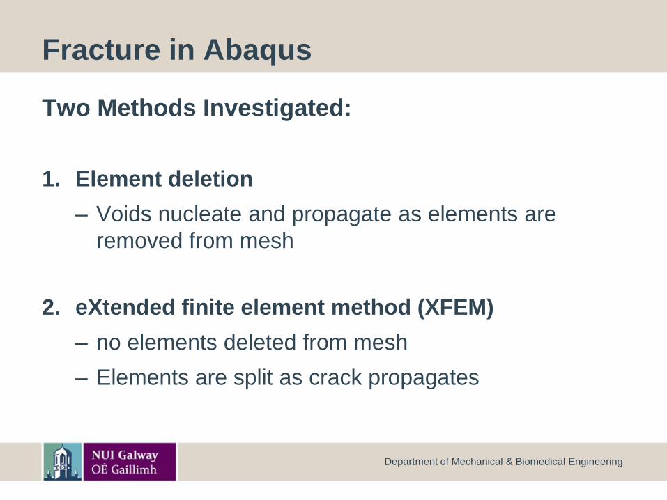
Fracture in Abaqus
Two Methods Investigated:
1. Element deletion
– Voids nucleate and propagate as elements are
removed from mesh
2. eXtended finite element method (XFEM)
– no elements deleted from mesh
– Elements are split as crack propagates
Department of Mechanical & Biomedical Engineering
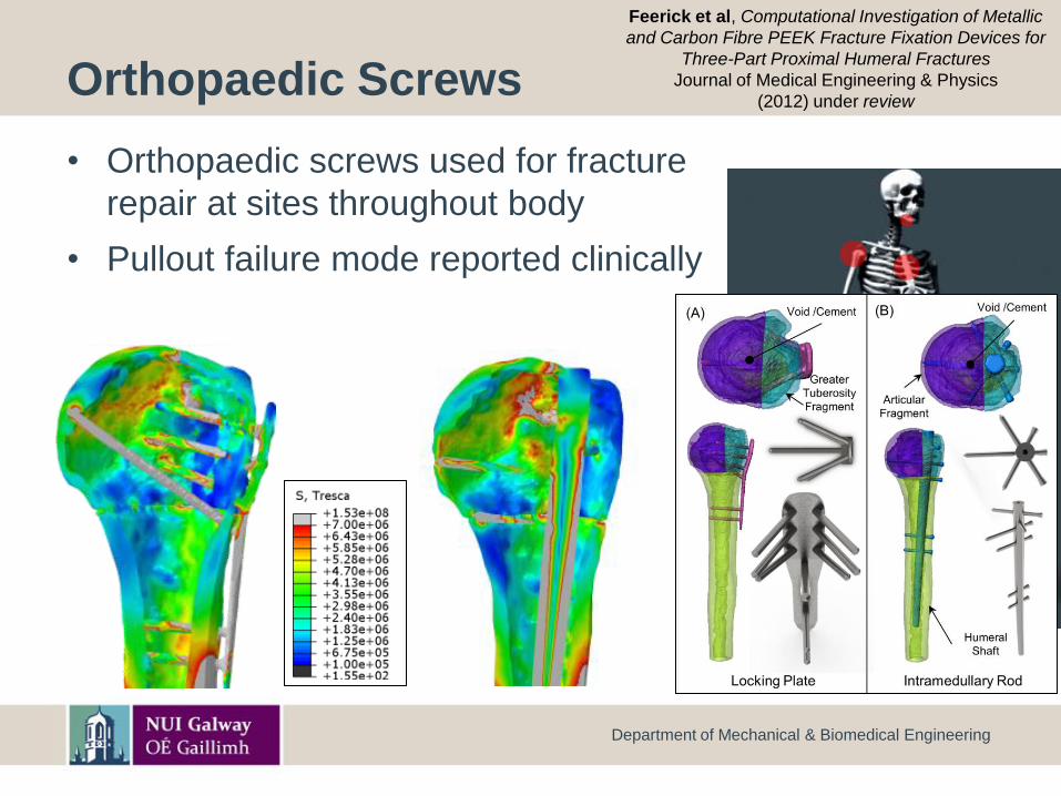
Orthopaedic Screws
• Orthopaedic screws used for fracture
repair at sites throughout body
• Pullout failure mode reported clinically
Department of Mechanical & Biomedical Engineering
Feerick et al, Computational Investigation of Metallic
and Carbon Fibre PEEK Fracture Fixation Devices for
Three-Part Proximal Humeral Fractures
Journal of Medical Engineering & Physics
(2012) under review
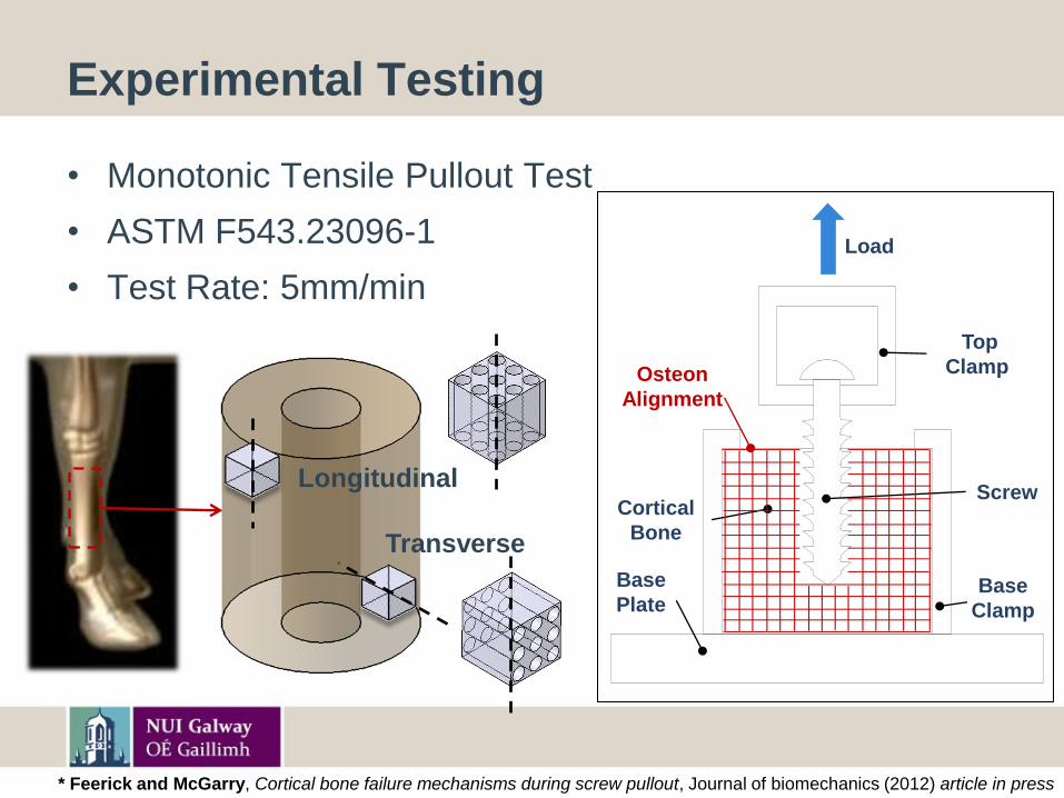
Experimental Testing
• Monotonic Tensile Pullout Test
• ASTM F543.23096-1
• Test Rate: 5mm/min
Longitudinal
Transverse
Load
Base
Plate
Cortical
Bone
Base
Clamp
Screw
Top
ClampOsteon
Alignment
* Feerick and McGarry, Cortical bone failure mechanisms during screw pullout, Journal of biomechanics (2012) article in press
Department of Mechanical & Biomedical Engineering
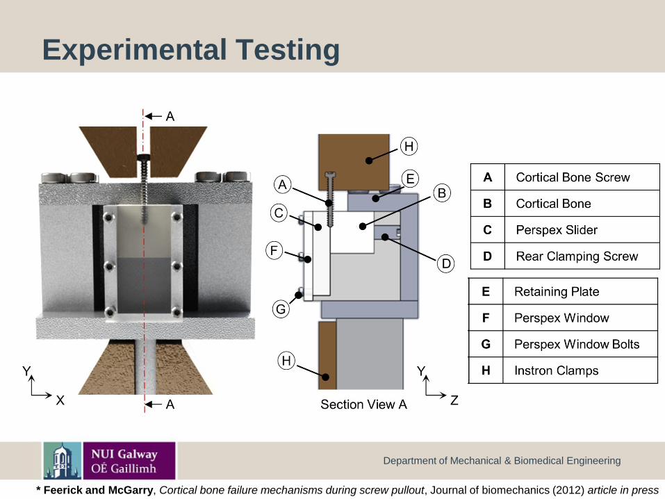
Experimental Testing
* Feerick and McGarry, Cortical bone failure mechanisms during screw pullout, Journal of biomechanics (2012) article in press
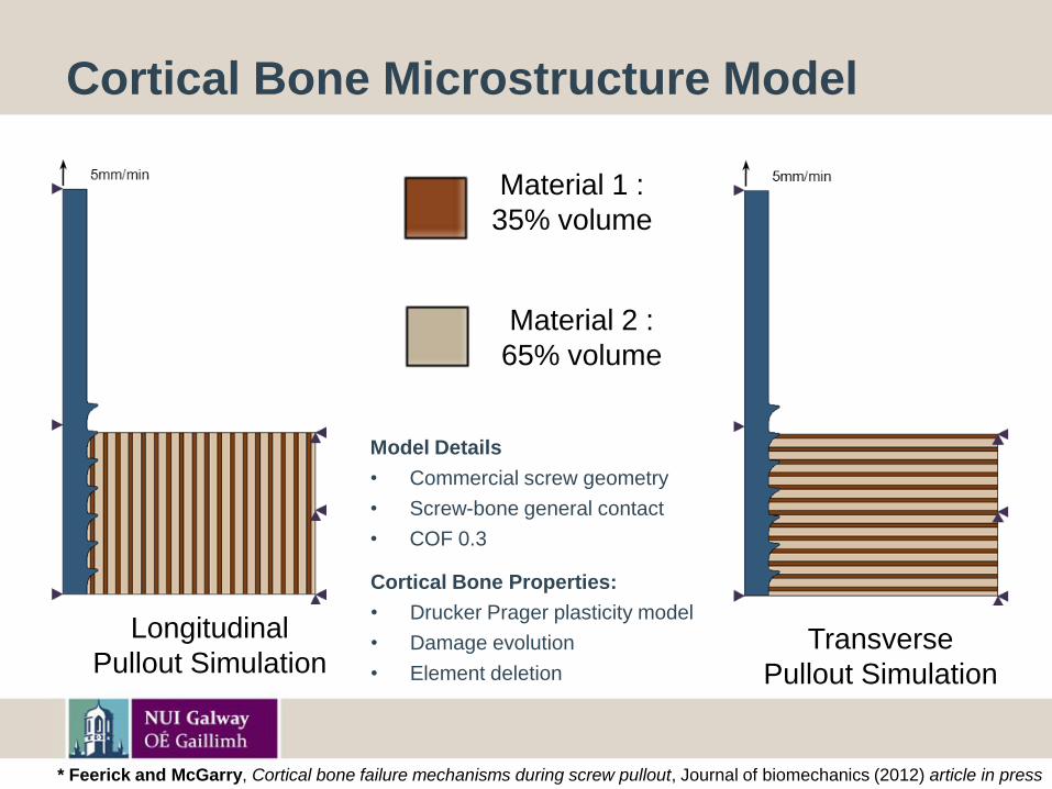
Cortical Bone Microstructure Model
Longitudinal
Pullout SimulationTransverse
Pullout Simulation
Material 1 :
35% volume
Material 2 :
65% volume
Model Details
• Commercial screw geometry
• Screw-bone general contact
• COF 0.3
Cortical Bone Properties:
• Drucker Prager plasticity model
• Damage evolution
• Element deletion
* Feerick and McGarry, Cortical bone failure mechanisms during screw pullout, Journal of biomechanics (2012) article in press
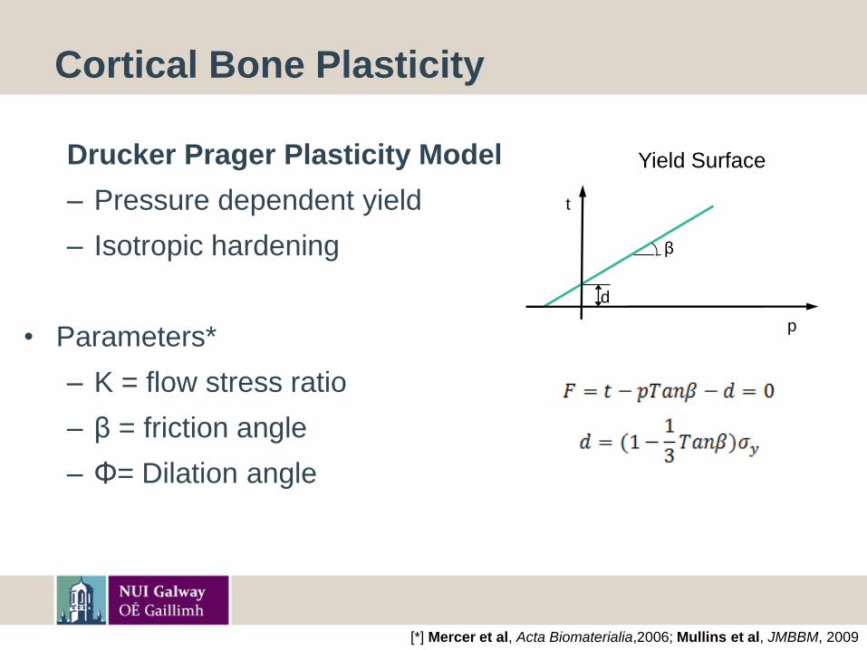
Cortical Bone Plasticity
Drucker Prager Plasticity Model
– Pressure dependent yield
– Isotropic hardening
• Parameters*
– K = flow stress ratio
– β = friction angle
– Φ= Dilation angle
[*] Mercer et al, Acta Biomaterialia,2006; Mullins et al, JMBBM, 2009
d
β
t
p
Yield Surface
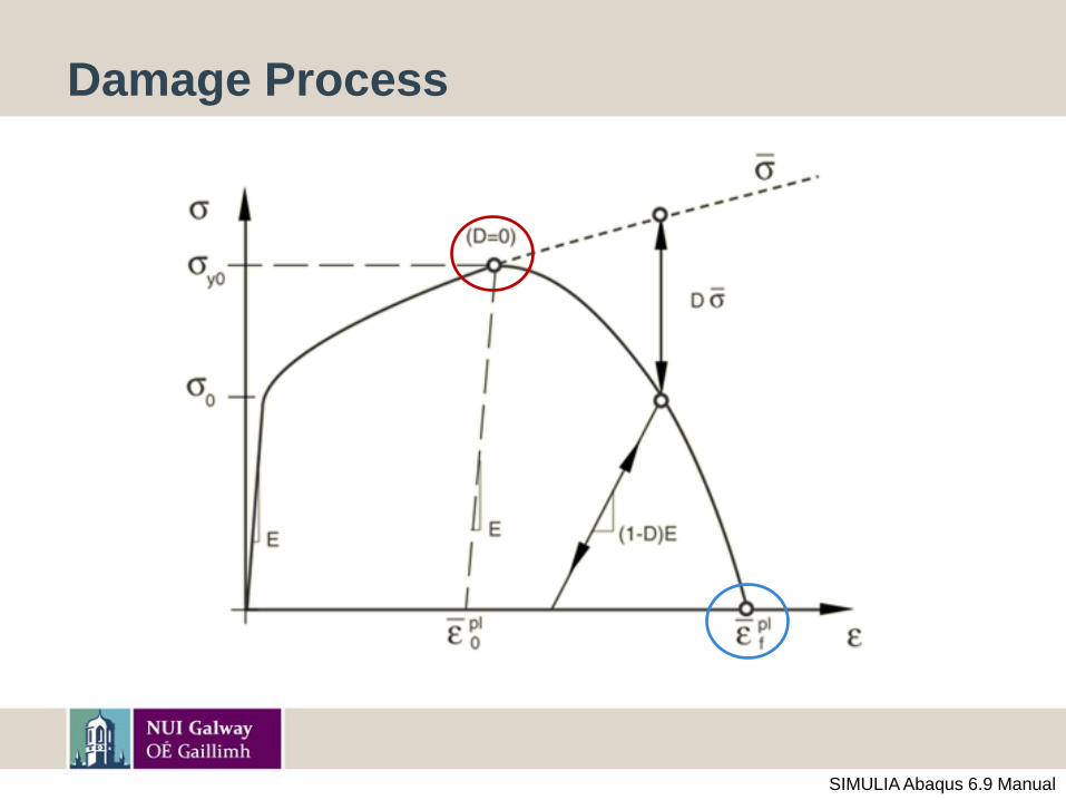
Damage Process
SIMULIA Abaqus 6.9 Manual
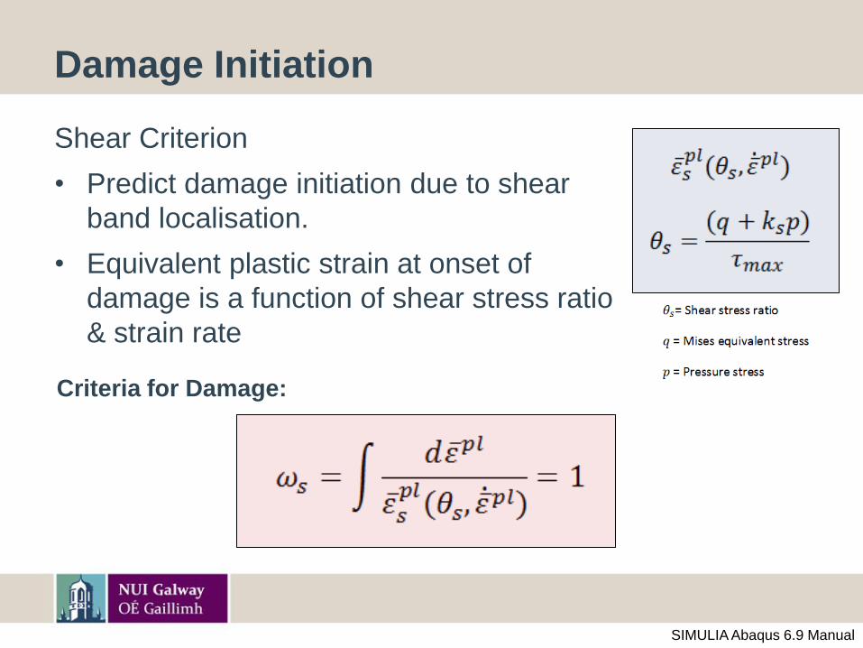
Damage Initiation
Shear Criterion
• Predict damage initiation due to shear
band localisation.
• Equivalent plastic strain at onset of
damage is a function of shear stress ratio
& strain rate
Criteria for Damage:
SIMULIA Abaqus 6.9 Manual
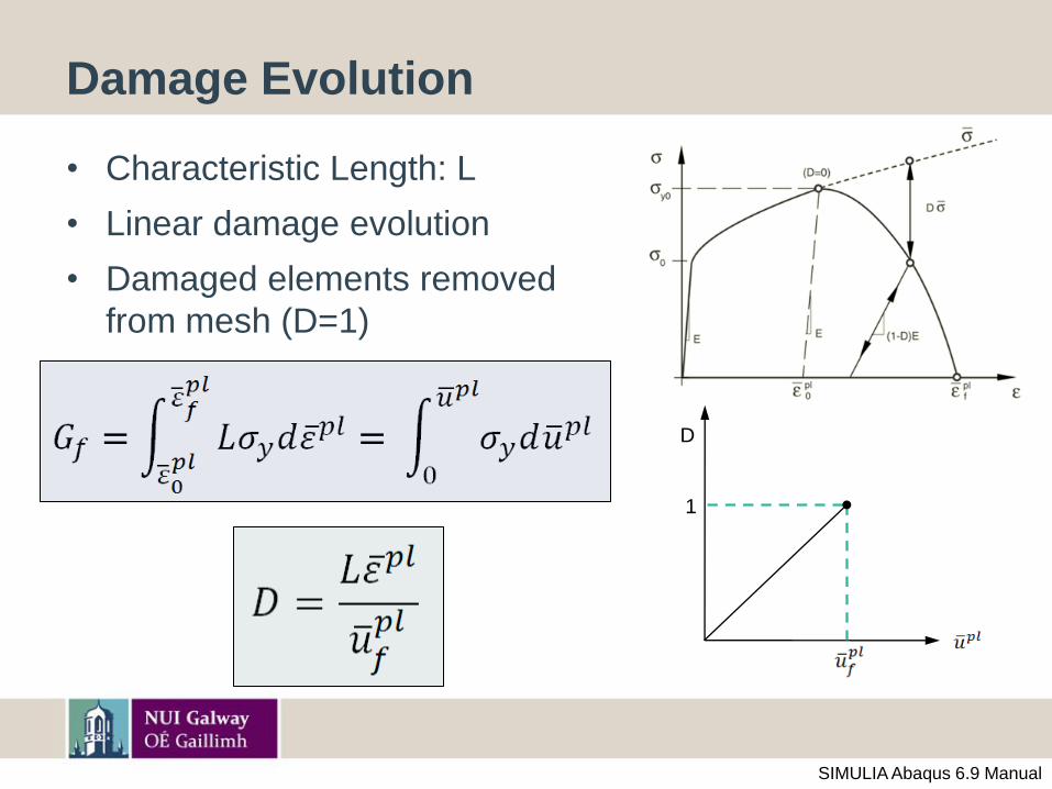
Damage Evolution
• Characteristic Length: L
• Linear damage evolution
• Damaged elements removed
from mesh (D=1)
1
D
SIMULIA Abaqus 6.9 Manual
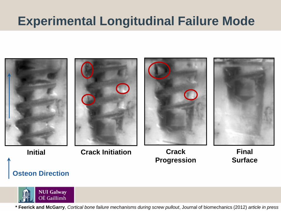
Experimental Longitudinal Failure Mode
Initial Crack Initiation Crack
Progression
Final
Surface
Osteon Direction
* Feerick and McGarry, Cortical bone failure mechanisms during screw pullout, Journal of biomechanics (2012) article in press
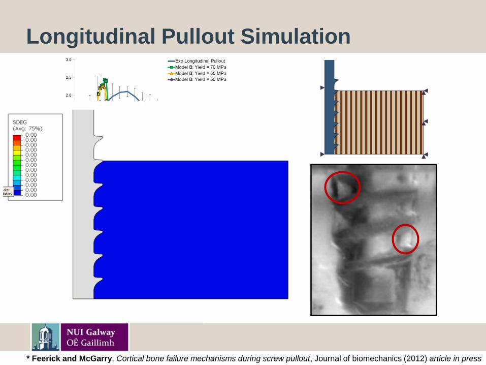
Longitudinal Pullout Simulation
* Feerick and McGarry, Cortical bone failure mechanisms during screw pullout, Journal of biomechanics (2012) article in press
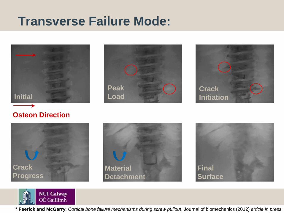
Transverse Failure Mode:
Initial
Peak
LoadCrack
Initiation
Final
Surface
Material
Detachment
Crack
Progress
Osteon Direction
* Feerick and McGarry, Cortical bone failure mechanisms during screw pullout, Journal of biomechanics (2012) article in press
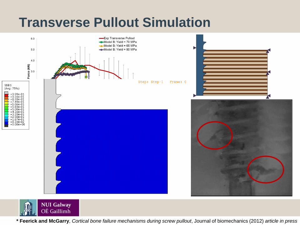
Transverse Pullout Simulation
* Feerick and McGarry, Cortical bone failure mechanisms during screw pullout, Journal of biomechanics (2012) article in press
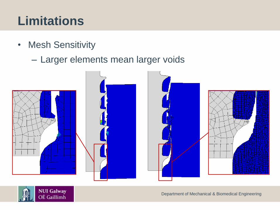
Limitations
• Mesh Sensitivity
– Larger elements mean larger voids
Department of Mechanical & Biomedical Engineering
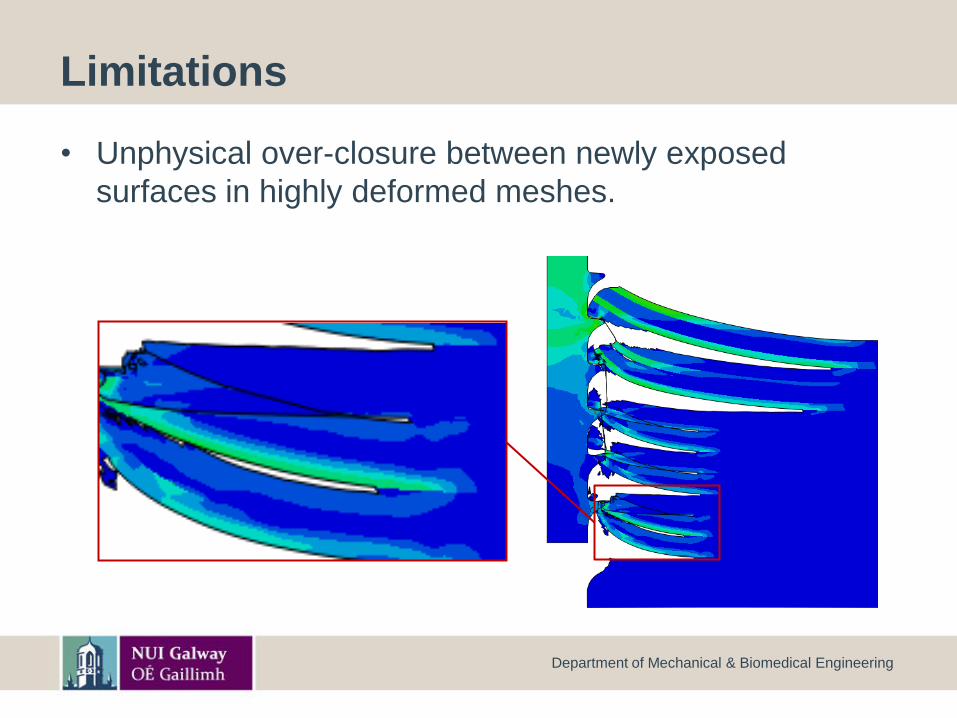
Limitations
• Unphysical over-closure between newly exposed
surfaces in highly deformed meshes.
Department of Mechanical & Biomedical Engineering
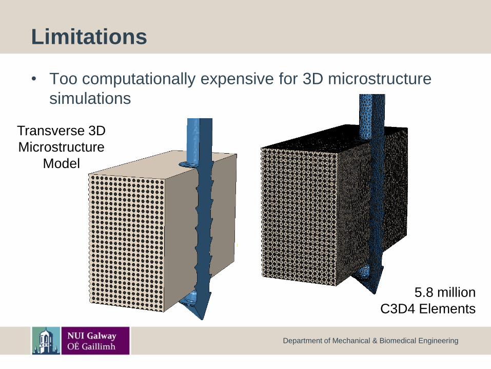
Limitations
• Too computationally expensive for 3D microstructure
simulations
Department of Mechanical & Biomedical Engineering
5.8 million
C3D4 Elements
Transverse 3D
Microstructure
Model
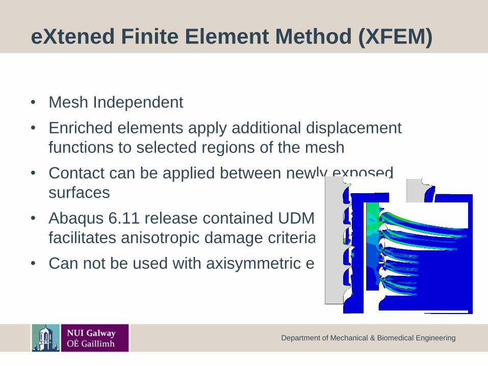
eXtened Finite Element Method (XFEM)
• Mesh Independent
• Enriched elements apply additional displacement
functions to selected regions of the mesh
• Contact can be applied between newly exposed
surfaces
• Abaqus 6.11 release contained UDMGINI which
facilitates anisotropic damage criteria to be defined
• Can not be used with axisymmetric elements
Department of Mechanical & Biomedical Engineering
t
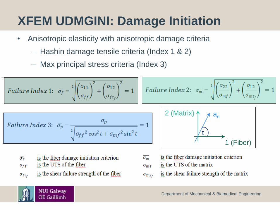
XFEM UDMGINI: Damage Initiation
Department of Mechanical & Biomedical Engineering
• Anisotropic elasticity with anisotropic damage criteria
– Hashin damage tensile criteria (Index 1 & 2)
– Max principal stress criteria (Index 3)
1 (Fiber)
2 (Matrix) an
1 (fiber)
2 (Matrix)
Crack
1 (fiber)
2 (Matrix) Crackt
1 (fiber)
2 (Matrix)
anCrack
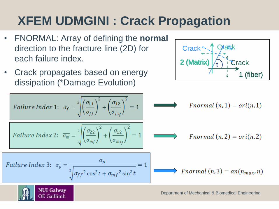
XFEM UDMGINI : Crack Propagation
• FNORMAL: Array of defining the normal
direction to the fracture line (2D) for
each failure index.
• Crack propagates based on energy
dissipation (*Damage Evolution)
Department of Mechanical & Biomedical Engineering
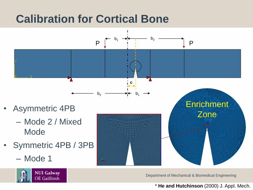
Calibration for Cortical Bone
• Asymmetric 4PB
– Mode 2 / Mixed
Mode
• Symmetric 4PB / 3PB
– Mode 1
Department of Mechanical & Biomedical Engineering
P P
c
b1b2
b1b2
Enrichment
Zone
* He and Hutchinson (2000) J. Appl. Mech.
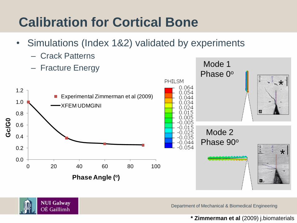
Calibration for Cortical Bone
• Simulations (Index 1&2) validated by experiments
– Crack Patterns
– Fracture Energy
Department of Mechanical & Biomedical Engineering
Mode 1
Phase 0o
Mode 2
Phase 90o
*
*Osteon
Direction
Transverse
0.0
0.2
0.4
0.6
0.8
1.0
1.2
0 20 40 60 80 100
Gc
/G0
Phase Angle (o)
Experimental Zimmerman et al (2009)
XFEM UDMGINI
* Zimmerman et al (2009) j.biomaterials
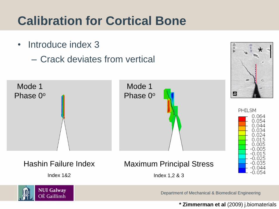
Calibration for Cortical Bone
• Introduce index 3
– Crack deviates from vertical
Department of Mechanical & Biomedical Engineering
Mode 1
Phase 0o
*
Hashin Failure Index
Index 1&2
Mode 1
Phase 0o
Maximum Principal Stress
Index 1,2 & 3
* Zimmerman et al (2009) j.biomaterials
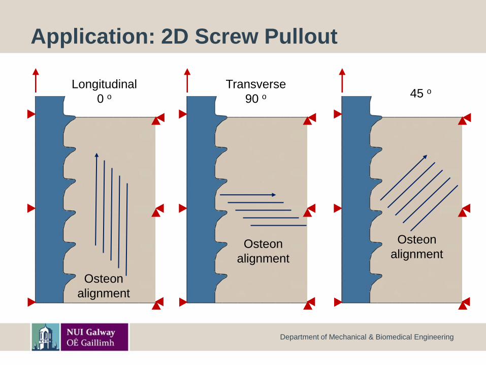
Application: 2D Screw Pullout
Department of Mechanical & Biomedical Engineering
Osteon
alignment
Longitudinal
0 o
Osteon
alignment
Transverse
90 o
Osteon
alignment
45 o
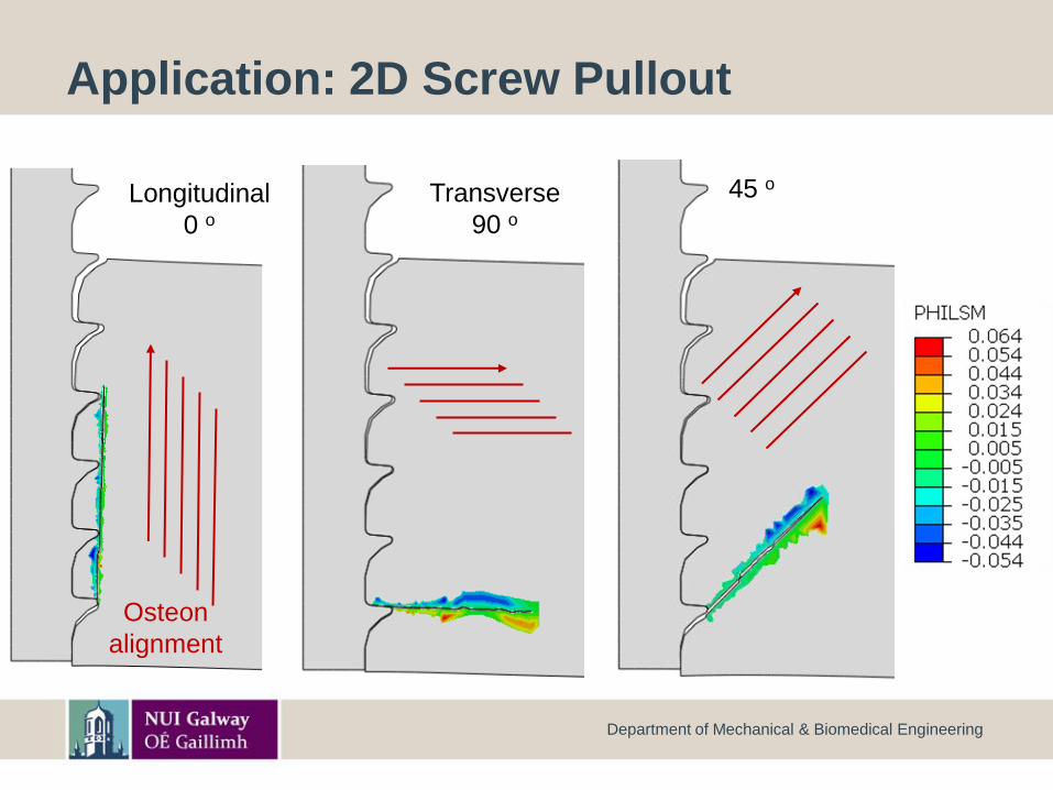
Application: 2D Screw Pullout
Department of Mechanical & Biomedical Engineering
Transverse
90 o45 oLongitudinal
0 o
Osteon
alignment
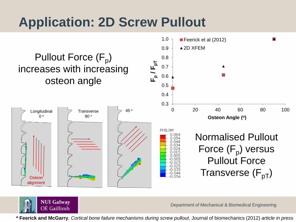
Application: 2D Screw Pullout
Department of Mechanical & Biomedical Engineering
Pullout Force (Fp)
increases with increasing
osteon angle
Normalised Pullout
Force (Fp) versus
Pullout Force
Transverse (FpT)
0.3
0.4
0.5
0.6
0.7
0.8
0.9
1.0
0 20 40 60 80 100
Fp
/ F
pT
Osteon Angle (o)
Feerick et al (2012)
2D XFEM
Transverse
90 o45 oLongitudinal
0 o
Osteon
alignment
* Feerick and McGarry, Cortical bone failure mechanisms during screw pullout, Journal of biomechanics (2012) article in press
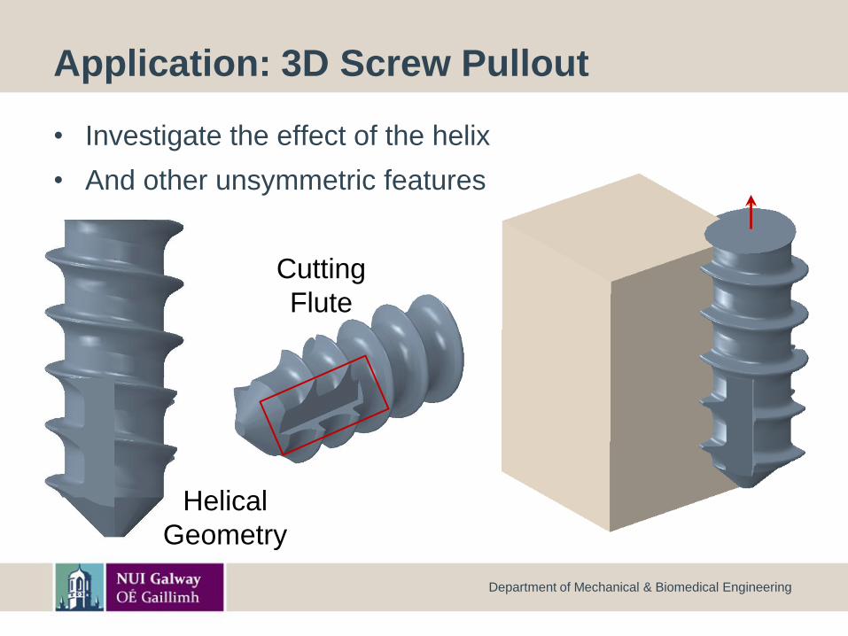
Application: 3D Screw Pullout
• Investigate the effect of the helix
• And other unsymmetric features
Department of Mechanical & Biomedical Engineering
Helical
Geometry
Cutting
Flute
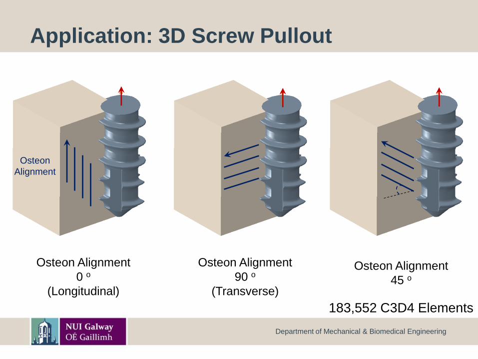
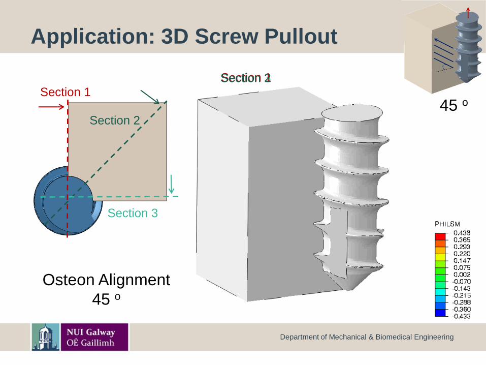
Application: 3D Screw Pullout
Department of Mechanical & Biomedical Engineering
Osteon Alignment
0 o
(Longitudinal)
Osteon Alignment
90 o
(Transverse)
Osteon
Alignment
Osteon Alignment
45 o
183,552 C3D4 Elements
Section 3Section 2
Section 2
Section 1
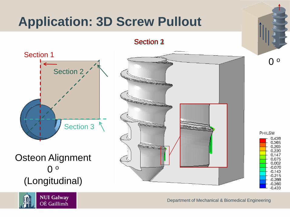
Application: 3D Screw Pullout
Department of Mechanical & Biomedical Engineering
Section 3
Osteon Alignment
0 o
(Longitudinal)
Section 1
0 o
Section 2
Section 2
Section 1
Section 1
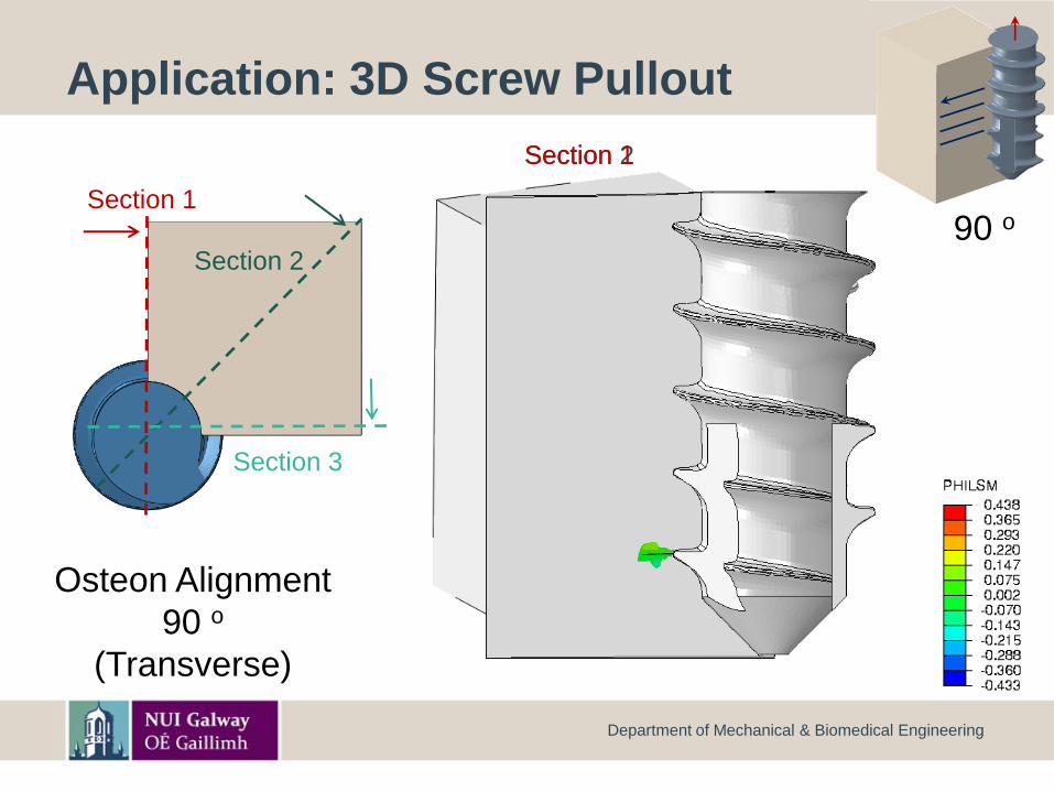
Application: 3D Screw Pullout
Department of Mechanical & Biomedical Engineering
Section 3
Osteon Alignment
90 o
(Transverse)
Osteon Alignment
90 o
(Transverse)
90 o
Section 3
Section 2
Section 1
Application: 3D Screw Pullout
Department of Mechanical & Biomedical Engineering
Section 3
Osteon Alignment
45 o
Section 1Section 2
Osteon Alignment
45 o
45 o
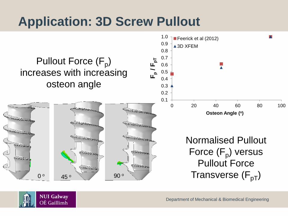
Application: 3D Screw Pullout
Department of Mechanical & Biomedical Engineering
0.1
0.2
0.3
0.4
0.5
0.6
0.7
0.8
0.9
1.0
0 20 40 60 80 100
Fp
/ F
pT
Osteon Angle (o)
Feerick et al (2012)
3D XFEM
0 o 90 o45 o
Pullout Force (Fp)
increases with increasing
osteon angle
Normalised Pullout
Force (Fp) versus
Pullout Force
Transverse (FpT)
Longitudinal
0 o
Osteon
alignment
Transverse
90 o
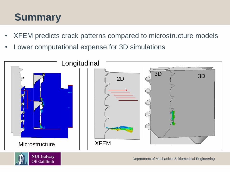
Summary
• XFEM predicts crack patterns compared to microstructure models
• Lower computational expense for 3D simulations
Department of Mechanical & Biomedical Engineering
Microstructure
2D3D
XFEM
TransverseLongitudinal
3D


![Untitled-2 [content.haycdn.com] · 2014-02-18 · Connect pullout hose (#11) to copper tube. see details on page 2 8. Place the weight (#9) onto pullout hose (#11). 9. Screw in the](https://img.pdfslide.net/doc/110x75/5fa233bf2e4f2d01d517d43c/untitled-2-2014-02-18-connect-pullout-hose-11-to-copper-tube-see-details.jpg)