Embed Size (px)
Citation preview
Computer Fundamentalsand
Operating System TheoryBy Neil Bloomberg
Spring 2017
INTRODUCTION
This presentation will cover the fundamentals of Computer Operating Systems as a layered architecture using the basic building blocks of the hardware as a point of reference.
AGENDA
• Hardware Architecture
• Single Cycle vs Multi Cycle CPU's
• Operating Systems - A layered Architecture
• The Process Scheduler - The heart of the System
• Multitasking and Multi-threading Operating Systems
• Q & A
Bonus Material
• CPU Internals, lessons from the Z80 Microprocessor
• Disk Drive fundamentals
• Memory (DRAM, PROM, SRAM, etc.)
Acknowledgements etc.
All Click art used in this presentation was obtained from Wikipedia unless otherwise noted.
Slide Take-Away Points are designed with an Arrow and highlighted at the bottom in bold RED.
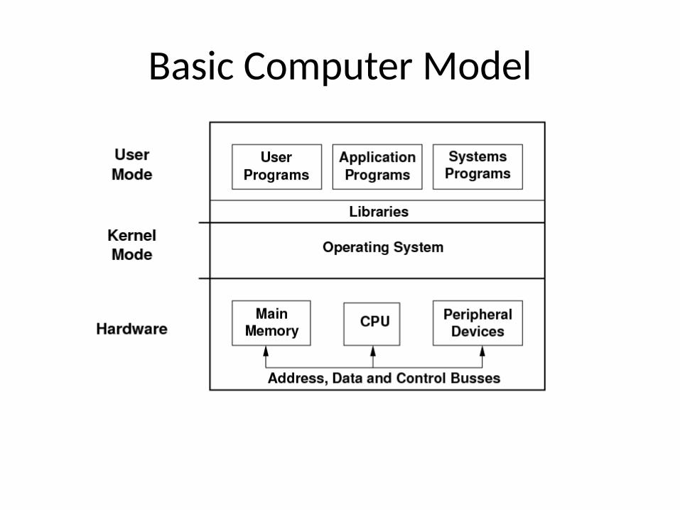
Basic Computer Model
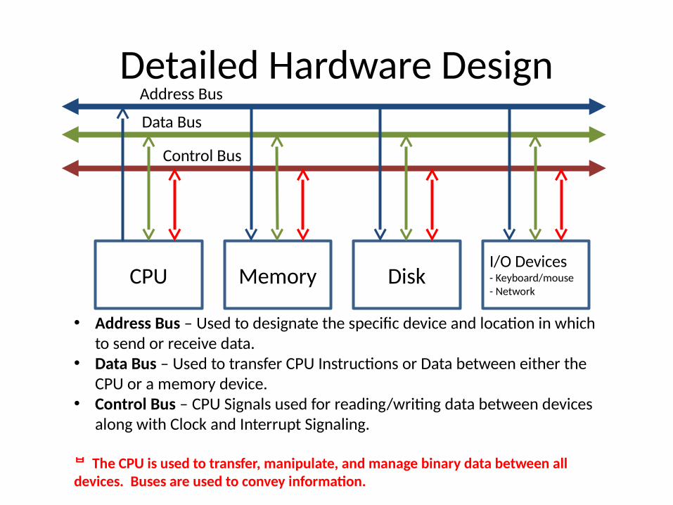
Detailed Hardware Design
CPU Memory DiskI/O Devices- Keyboard/mouse- Network
Address Bus
Data Bus
Control Bus
• Address Bus – Used to designate the specific device and location in which to send or receive data.
• Data Bus – Used to transfer CPU Instructions or Data between either the CPU or a memory device.
• Control Bus – CPU Signals used for reading/writing data between devices along with Clock and Interrupt Signaling.
The CPU is used to transfer, manipulate, and manage binary data between all devices. Buses are used to convey information.
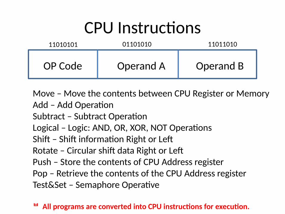
CPU Instructions
OP Code Operand A Operand B
Move – Move the contents between CPU Register or MemoryAdd – Add OperationSubtract – Subtract OperationLogical – Logic: AND, OR, XOR, NOT OperationsShift – Shift information Right or LeftRotate – Circular shift data Right or LeftPush – Store the contents of CPU Address registerPop – Retrieve the contents of the CPU Address registerTest&Set – Semaphore Operative
All programs are converted into CPU instructions for execution.
11010101 01101010 11011010
Types of CPU’sThere are basically two type of Processors:
• Single Cycle, in which the OP Code and Operands are contained in a single Unit confined to the width of the Data Bus. The CPU performs a OP Code Fetch on the Rising Edge of the Clock and Execution takes place on the Falling Edge of the Clock. (e.g. ARM, RISC, DSP, Most Video Processors, and SPARC Chips)
• Multi-Cycle, in which the OP Code is retrieved by the CPU during one phase, then each Operand is retrieved in successive phases, followed by the execution of the Instruction in following phases. (e.g. X86 Processor, 68000, and most other Processors). A Phase consists of one or more Clock Cycles as illustrated in the following slide.
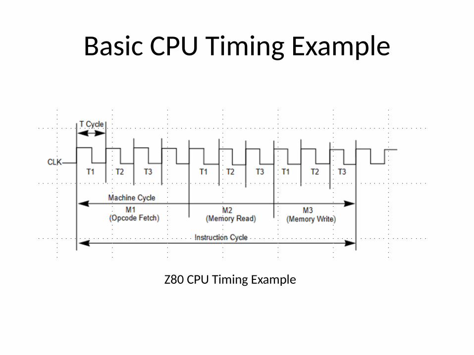
Basic CPU Timing Example
Z80 CPU Timing Example
Contrasts
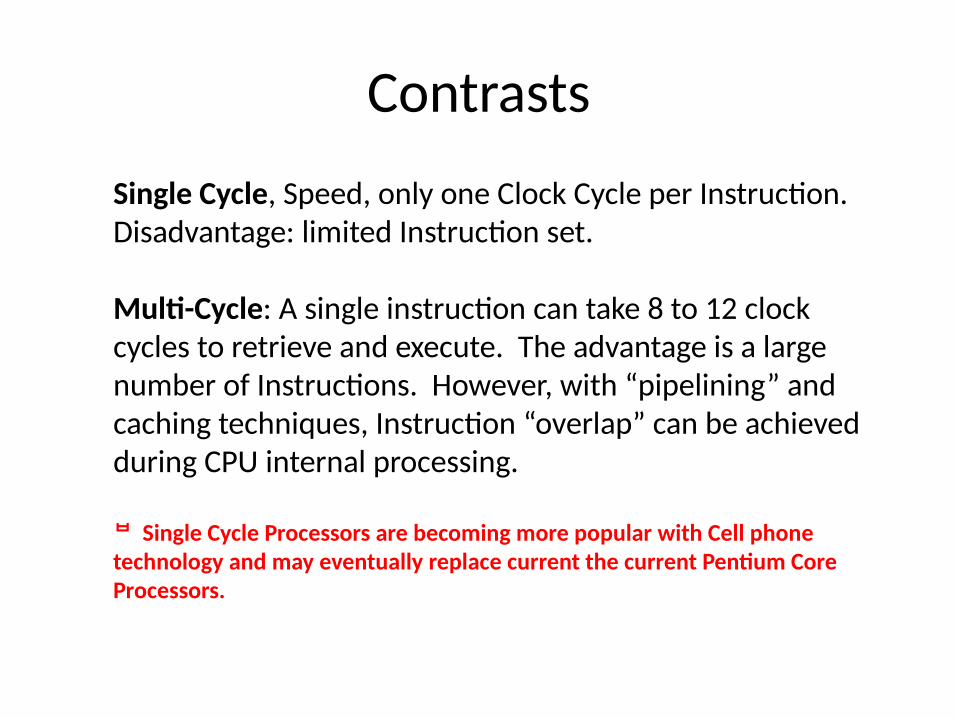
Single Cycle, Speed, only one Clock Cycle per Instruction. Disadvantage: limited Instruction set.
Multi-Cycle: A single instruction can take 8 to 12 clock cycles to retrieve and execute. The advantage is a large number of Instructions. However, with “pipelining” and caching techniques, Instruction “overlap” can be achieved during CPU internal processing.
Single Cycle Processors are becoming more popular with Cell phone technology and may eventually replace current the current Pentium Core Processors.
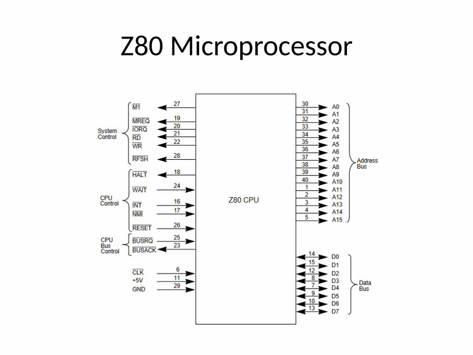
Z80 Microprocessor
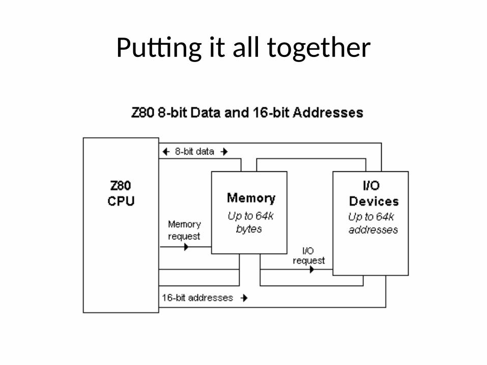
Putting it all together
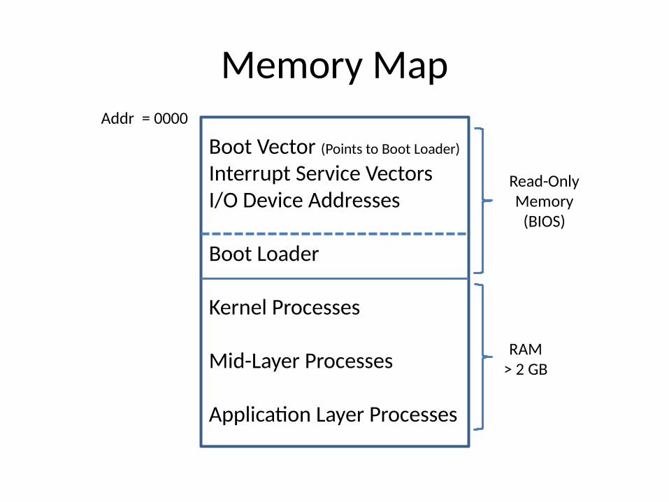
Memory Map
Boot Vector (Points to Boot Loader)
Interrupt Service VectorsI/O Device Addresses
Boot Loader
Kernel Processes
Mid-Layer Processes
Application Layer Processes
Addr = 0000
RAM> 2 GB
Read-OnlyMemory
(BIOS)
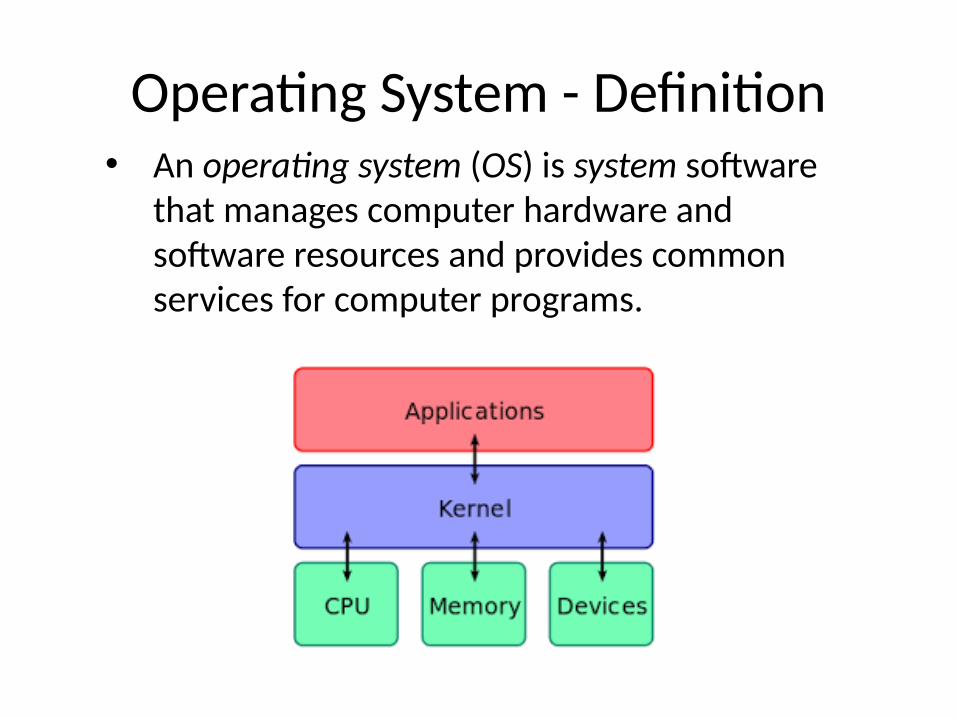
Operating System - Definition• An operating system (OS) is system software
that manages computer hardware and software resources and provides common services for computer programs.
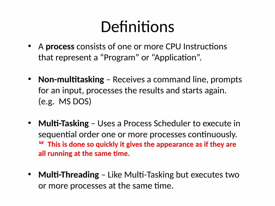
Definitions• A process consists of one or more CPU Instructions
that represent a “Program” or “Application”.
• Non-multitasking – Receives a command line, prompts for an input, processes the results and starts again. (e.g. MS DOS)
• Multi-Tasking – Uses a Process Scheduler to execute in sequential order one or more processes continuously. This is done so quickly it gives the appearance as if they are all running at the same time.
• Multi-Threading – Like Multi-Tasking but executes two or more processes at the same time.
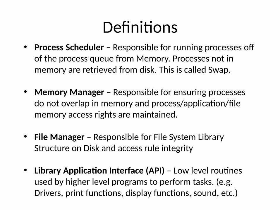
Definitions• Process Scheduler – Responsible for running processes off
of the process queue from Memory. Processes not in memory are retrieved from disk. This is called Swap.
• Memory Manager – Responsible for ensuring processes do not overlap in memory and process/application/file memory access rights are maintained.
• File Manager – Responsible for File System Library Structure on Disk and access rule integrity
• Library Application Interface (API) – Low level routines used by higher level programs to perform tasks. (e.g. Drivers, print functions, display functions, sound, etc.)
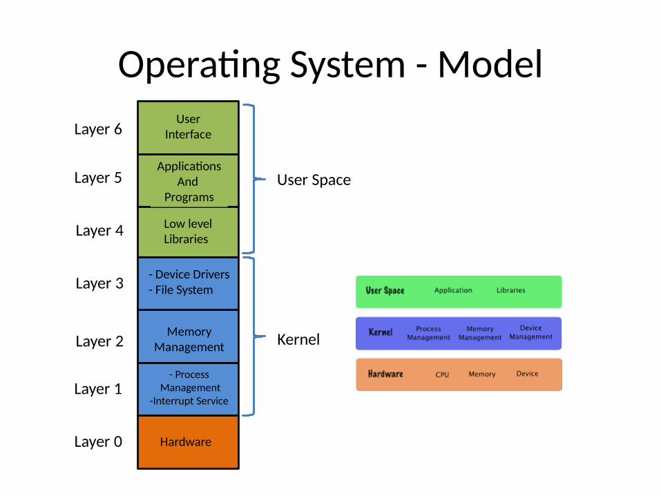
Operating System - Model
Hardware
- Process Management
-Interrupt Service
MemoryManagement
- Device Drivers- File System
Low level Libraries
ApplicationsAnd
Programs
UserInterfaceLayer 6
Layer 5
Layer 4
Layer 3
Layer 2
Layer 1
Layer 0
Kernel
User Space
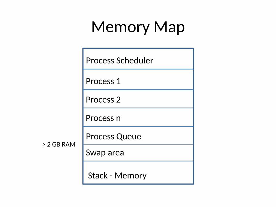
Memory Map
Process Scheduler
> 2 GB RAM
Process 1
Process 2
Process n
Process Queue
Swap area
Stack - Memory
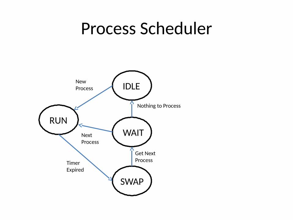
Process Scheduler
RUN
IDLE
SWAP
WAIT
TimerExpired
Get NextProcess
NewProcess
Nothing to Process
NextProcess
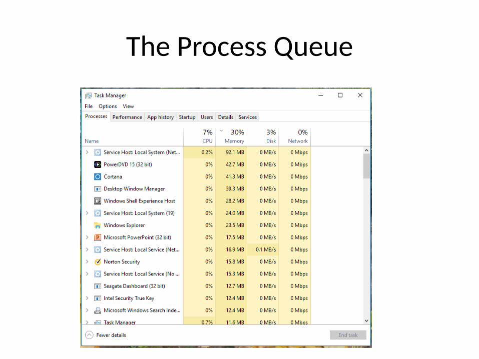
The Process Queue
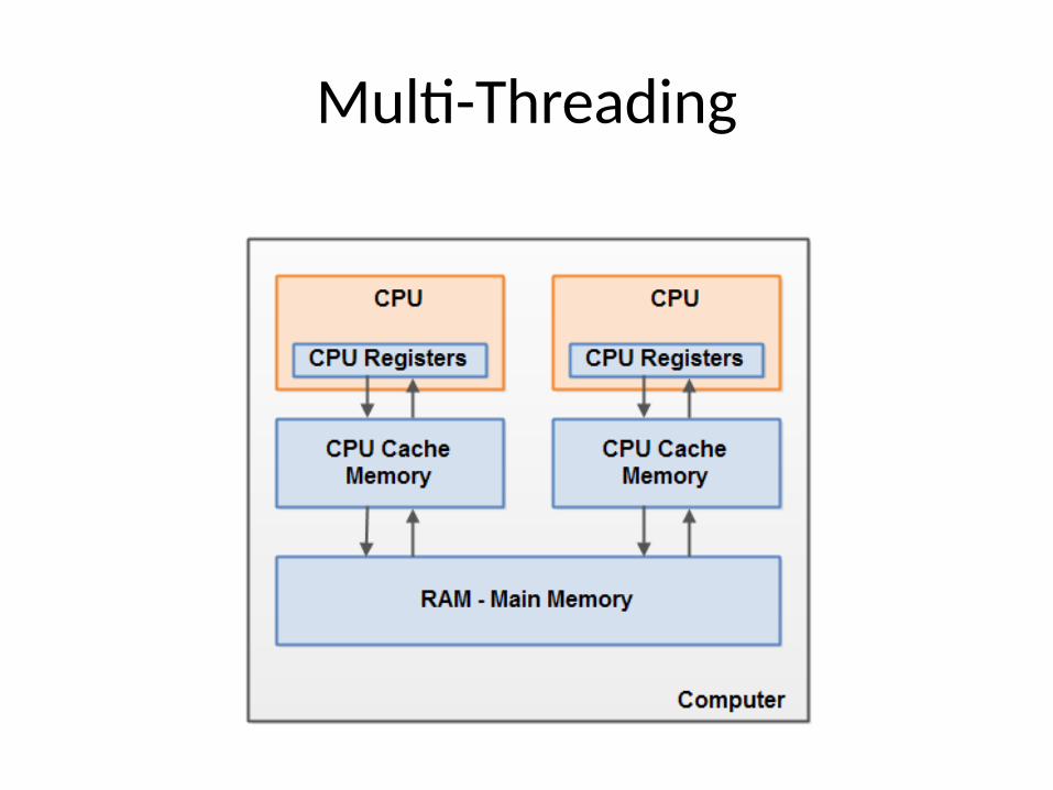
Multi-Threading
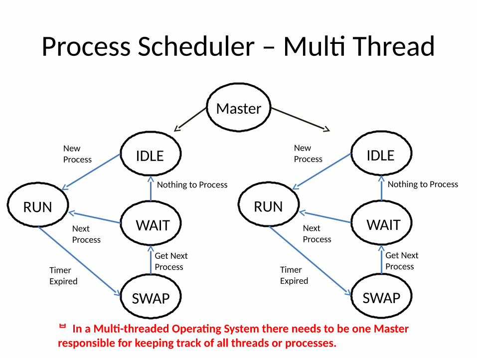
Process Scheduler – Multi Thread
RUN
IDLE
SWAP
WAIT
TimerExpired
Get NextProcess
NewProcess
Nothing to Process
NextProcess
RUN
IDLE
SWAP
WAIT
TimerExpired
Get NextProcess
NewProcess
Nothing to Process
NextProcess
Master
In a Multi-threaded Operating System there needs to be one Master responsible for keeping track of all threads or processes.
The SETI Example
Perhaps the largest and most famous Multi-Threaded Operating System in the World is the Search for Extra-terrestrial Intelligence (SETI) System. A huge Radio Telescope farm collects large chunks of information and then farms it out to regular computers to process and then report the results back to the master System.
Summary• The CPU is used to transfer, manipulate, and manage binary data
between all devices. Buses are used to convey information.
• All programs/applications are converted into CPU instructions for execution by the CPU.
• In a Multi-Tasking Operating System, processes are run for a brief period of time sequentially. This is done so quickly that it gives the appearance that they are all running at the same time.
• In Multi-threaded Operating System there needs to be one Master responsible for keeping track of all threads or processes.
• Understanding how the hardware and operating system work together can help you streamline and improve computer performance. (e.g. reducing unneeded processes, can speed up computer boot time and overall system speed)

Q & A ?????

Bonus Section
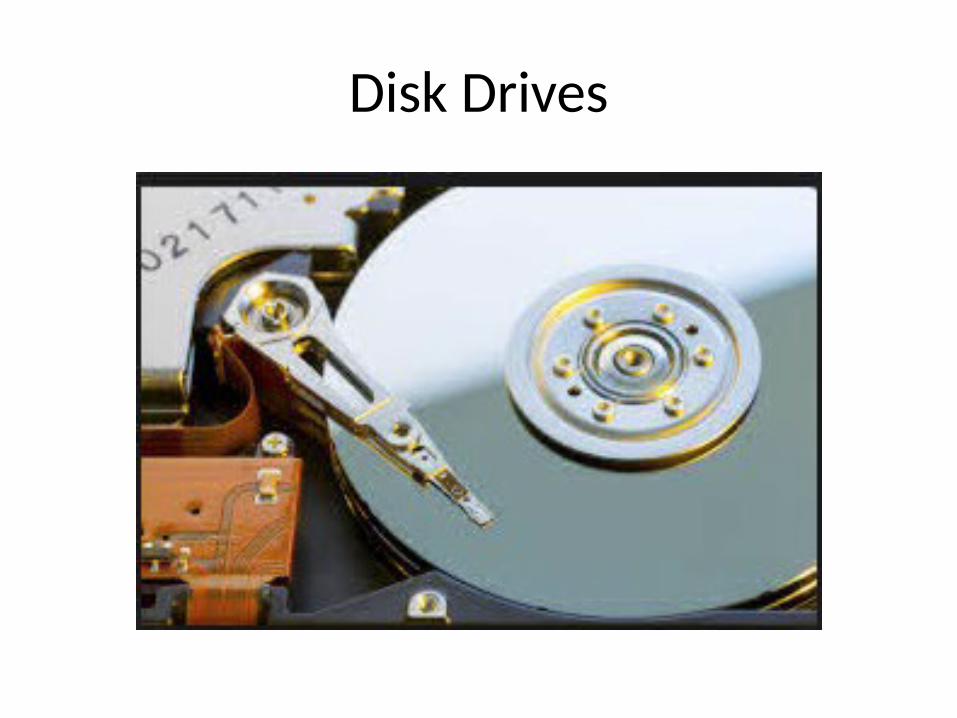
Disk Drives
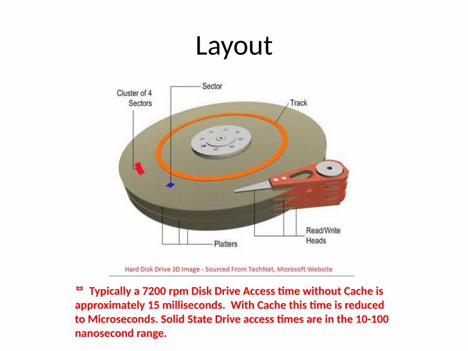
Layout
Typically a 7200 rpm Disk Drive Access time without Cache is approximately 15 milliseconds. With Cache this time is reduced to Microseconds. Solid State Drive access times are in the 10-100 nanosecond range.
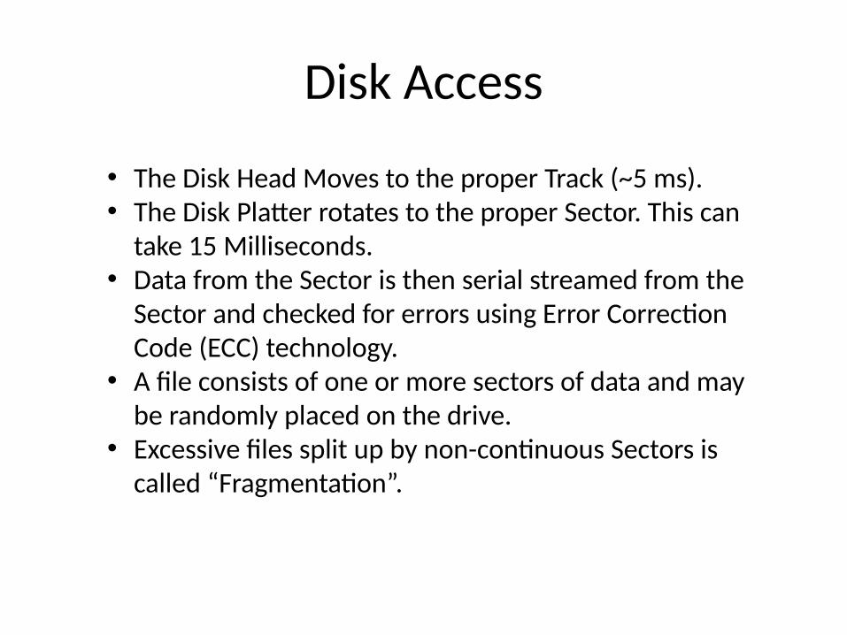
Disk Access
• The Disk Head Moves to the proper Track (~5 ms).• The Disk Platter rotates to the proper Sector. This can
take 15 Milliseconds.• Data from the Sector is then serial streamed from the
Sector and checked for errors using Error Correction Code (ECC) technology.
• A file consists of one or more sectors of data and may be randomly placed on the drive.
• Excessive files split up by non-continuous Sectors is called “Fragmentation”.
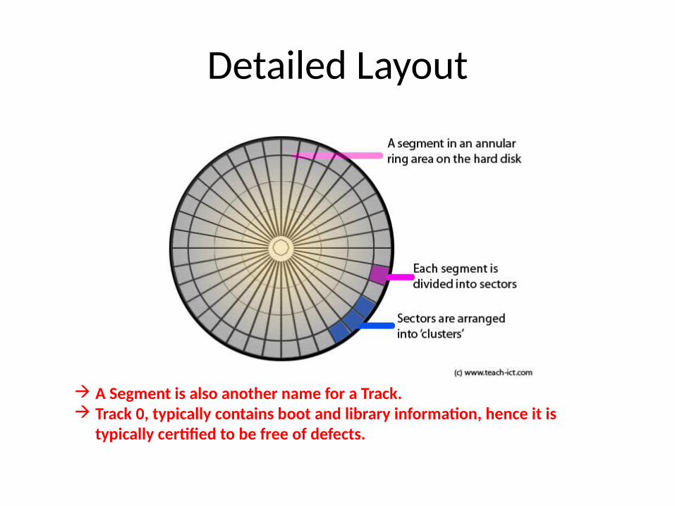
Detailed Layout
A Segment is also another name for a Track. Track 0, typically contains boot and library information, hence it is
typically certified to be free of defects.
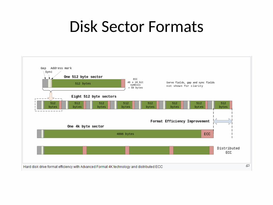
Disk Sector Formats
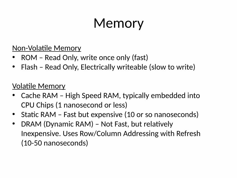
Memory
Non-Volatile Memory• ROM – Read Only, write once only (fast)• Flash – Read Only, Electrically writeable (slow to write)
Volatile Memory• Cache RAM – High Speed RAM, typically embedded into
CPU Chips (1 nanosecond or less)• Static RAM – Fast but expensive (10 or so nanoseconds)• DRAM (Dynamic RAM) – Not Fast, but relatively
Inexpensive. Uses Row/Column Addressing with Refresh (10-50 nanoseconds)
Future Topics
• Computer Network Basics• Digital Logic Basics• Basic Electronics• Operating Systems – Overview of UNIX• Fundamentals of Programming
Backup Slides
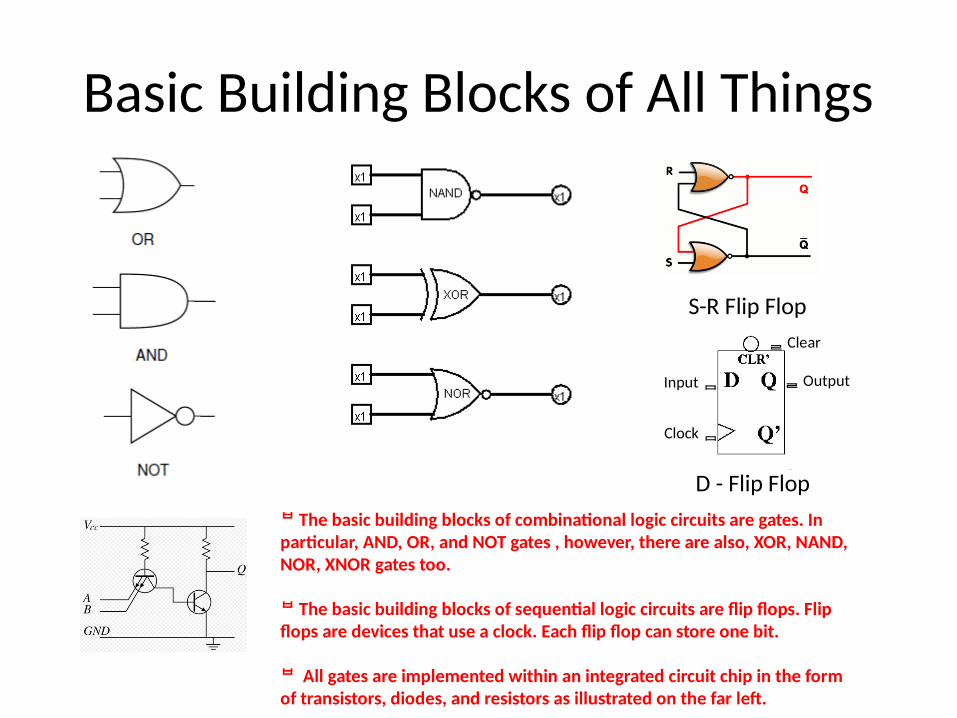
Basic Building Blocks of All Things
S-R Flip Flop
D - Flip Flop
The basic building blocks of combinational logic circuits are gates. In particular, AND, OR, and NOT gates , however, there are also, XOR, NAND, NOR, XNOR gates too.
The basic building blocks of sequential logic circuits are flip flops. Flip flops are devices that use a clock. Each flip flop can store one bit.
All gates are implemented within an integrated circuit chip in the form of transistors, diodes, and resistors as illustrated on the far left.
Input
Clock
Output
Clear
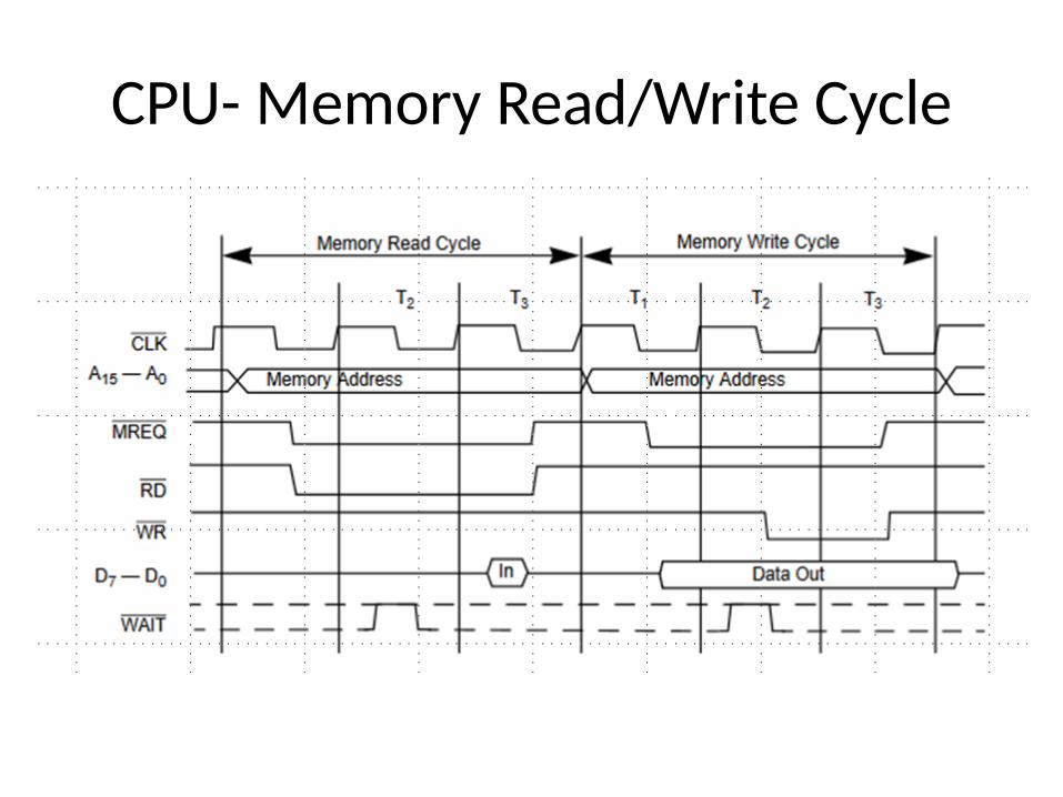
CPU- Memory Read/Write Cycle
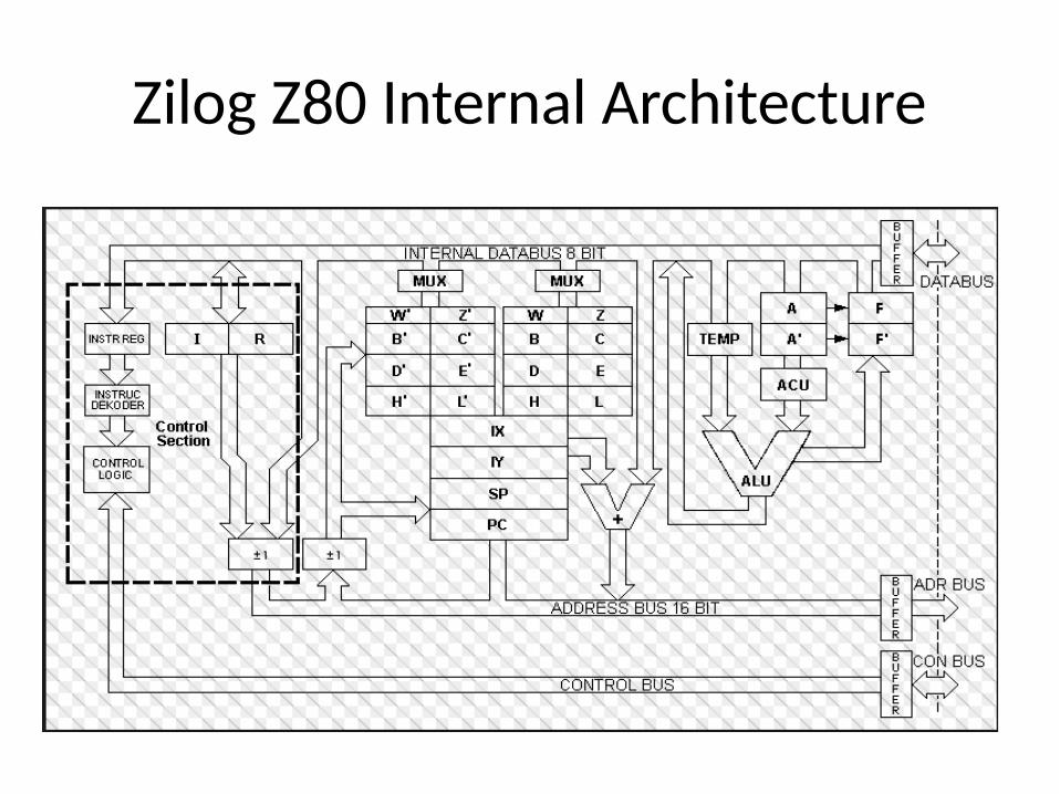
Zilog Z80 Internal Architecture
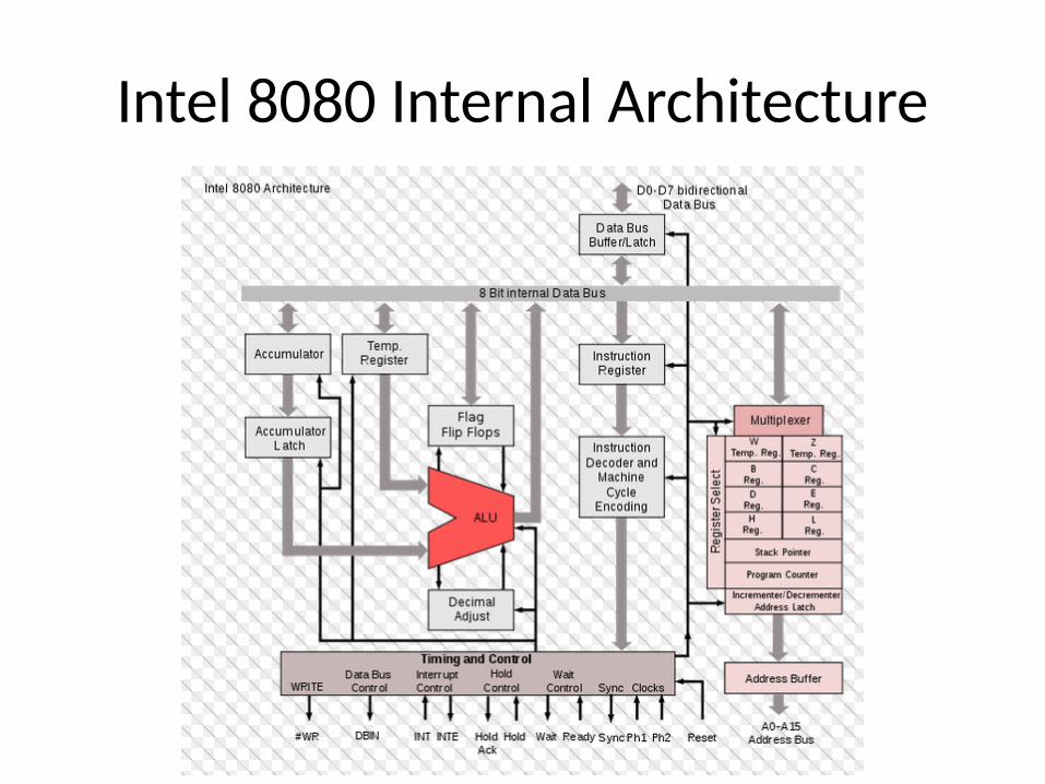
Intel 8080 Internal Architecture
Beowulf O.S.
A Beowulf cluster is a computer cluster of what are normally identical, commodity-grade computers networked into a small local area network with libraries and programs installed which allow processing to be shared among them. The result is a high-performance parallel computing cluster from inexpensive personal computer hardware.
The name Beowulf originally referred to a specific computer built in 1994 by Thomas Sterling and Donald Becker at NASA. The name "Beowulf" comes from the Old English epic poem of the same name.
Source: Wikipedia