Embed Size (px)
Citation preview
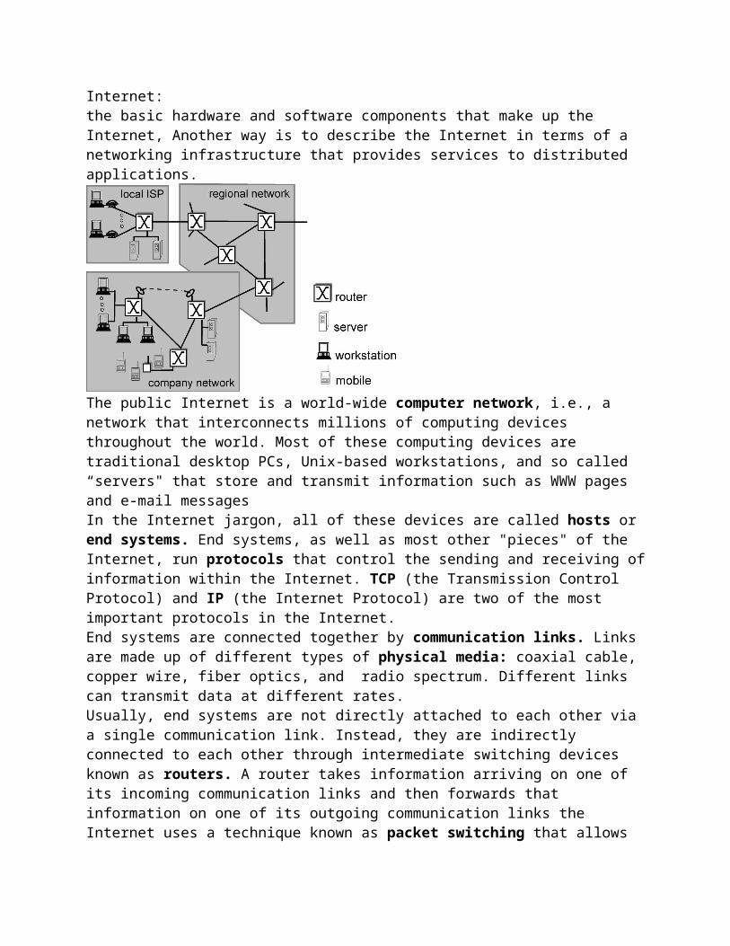
Internet:the basic hardware and software components that make up the Internet, Another way is to describe the Internet in terms of a networking infrastructure that provides services to distributed applications.
The public Internet is a world-wide computer network, i.e., a network that interconnects millions of computing devices throughout the world. Most of these computing devices are traditional desktop PCs, Unix-based workstations, and so called “servers" that store and transmit information such as WWW pages and e-mail messagesIn the Internet jargon, all of these devices are called hosts or end systems. End systems, as well as most other "pieces" of the Internet, run protocols that control the sending and receiving of information within the Internet. TCP (the Transmission Control Protocol) and IP (the Internet Protocol) are two of the most important protocols in the Internet. End systems are connected together by communication links. Links are made up of different types of physical media: coaxial cable, copper wire, fiber optics, and radio spectrum. Different links can transmit data at different rates.Usually, end systems are not directly attached to each other via a single communication link. Instead, they are indirectly connected to each other through intermediate switching devices known as routers. A router takes information arriving on one of its incoming communication links and then forwards that information on one of its outgoing communication links the Internet uses a technique known as packet switching that allows multiple communicating end systems to share a path, or parts of a path, at the same timeThe Internet is really a network of networks. That is, the Internet is an interconnected set of privately and publicly owned and managed networks. Any network connected to the Internet must run the IP protocol and conform to certain naming and addressing conventions.the structure of the interconnection among the various pieces of the Internet, is loosely hierarchical.A Service Description:The Internet allows distributed applications running on its end systems to exchange data with each other. These applications include remote login, file transfer, electronic mail, audio and video streaming, real-time audio and video conferencing, distributed games, the World Wide Web, and much much more
The Internet provides two services to its distributed applications: a connection-oriented service and a connectionless service. Loosely speaking, connection-oriented service guarantees that data transmitted from a sender to a receiver will eventually be delivered to the receiver in-order and in its entirety. Connectionless service does not make any guarantees about eventual delivery1.3 The Network Edge:In computer networking jargon, the computers that we use on a daily basis are often referred to as or hosts or end systems. They are referred to as "hosts" because they host (run) application-level programs such as a Web browser or server program, or an e-mail program. They are also referred to as "end systems" because they sit at the "edge" of the Internet.Hosts are sometimes further divided into two categories: clients and servers. Informally, clients often tend to be desktop PC's or workstations, while servers are more powerful machines. In the so-called client-server model, a client program running on one end system requests and receives information from a server running on another end system. The client and the server interact with each other by communicating (i.e., sending each other messages) over the Internet.
Connection less and connection oriented services:We have seen that end systems exchange messages with each other according to an application-level protocol in order to accomplish some task. The Internet, and more generally TCP/IP networks, provide two types of services to its applications: connectionless service and connection-oriented service.
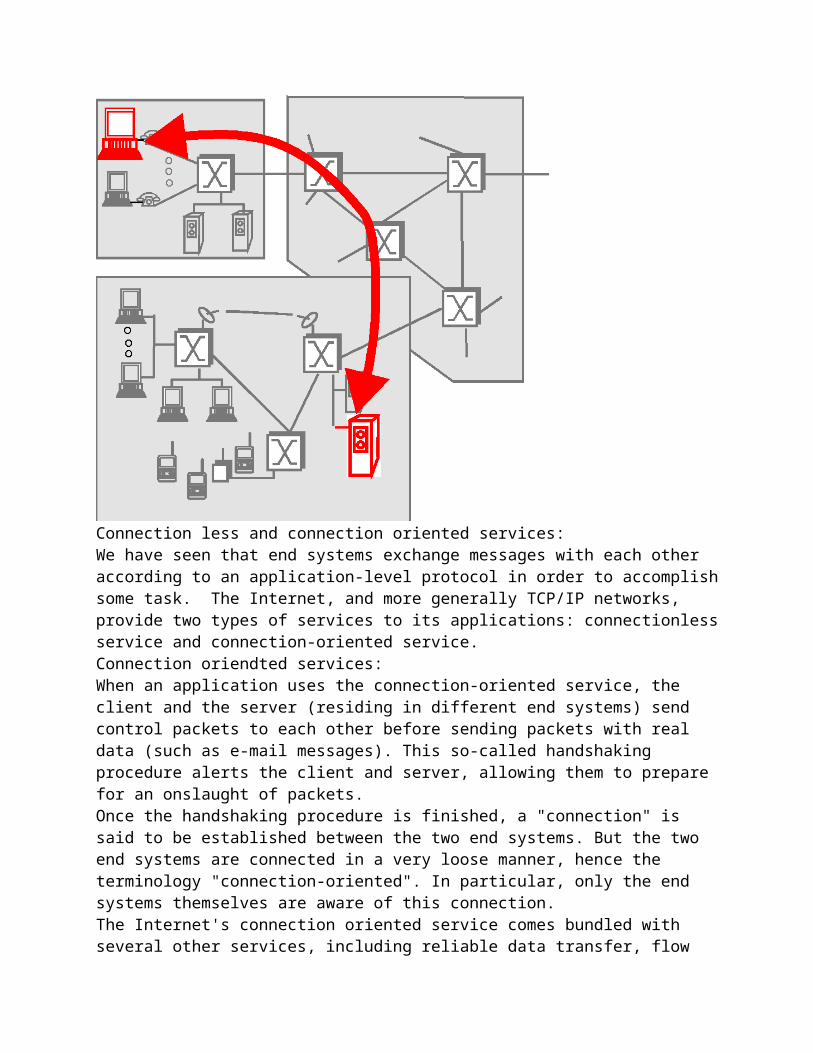
Connection oriendted services:When an application uses the connection-oriented service, the client and the server (residing in different end systems) send control packets to each other before sending packets with real data (such as e-mail messages). This so-called handshaking procedure alerts the client and server, allowing them to prepare for an onslaught of packets.Once the handshaking procedure is finished, a "connection" is said to be established between the two end systems. But the two end systems are connected in a very loose manner, hence the terminology "connection-oriented". In particular, only the end systems themselves are aware of this connection.The Internet's connection oriented service comes bundled with several other services, including reliable data transfer, flow control and congestion control. By reliable data transfer, we mean that an application can rely on the connection to deliver all of its data without error and in the proper order. Reliability in the Internet is achieved through the use of acknowledgments and retransmissions. To get a preliminary idea about how the Internet implements the reliable transport service, consider an application that has established a connection between end systems A and B. When end system B receives a packet from A, it sends an acknowledgment; when end system A receives the acknowledgment, it knows that the corresponding packet has definitely been received. When end system A doesn't receive an acknowledgment, it assumes that the packet it sent was not received by B; it therefore retransmits the packet.Flow control makes sure that neither side of a connection overwhelmsthe other side by sending too many packets too fast. Indeed, the application at one one side of the connection may not be able to process information as quickly as it receives the information. Therefore, there is a risk of overwhelming either side of an application. The flow-control service forces the sending end system to reduce its rate whenever there is such a risk.The Internet's congestion control service helps prevent the Internet from entering a state of grid lock. When a router becomes congested, its buffers can overflow and packet loss can occur In such circumstances, if every pair of communicating end systems continues to pump packets into the network as fast as they can, gridlock sets in and few packets are delivered to their destinationsConnection less services:There is no handshaking with the Internet's connectionless service. When one side of an application wants to send packets to another side of an application, the sending application simply sends the packets. Since there is no handshaking procedure prior to the transmission of the packets, data can be delivered faster. But there are no acknowledgments either, so a source never knows for sure which packets arrive at the destination.
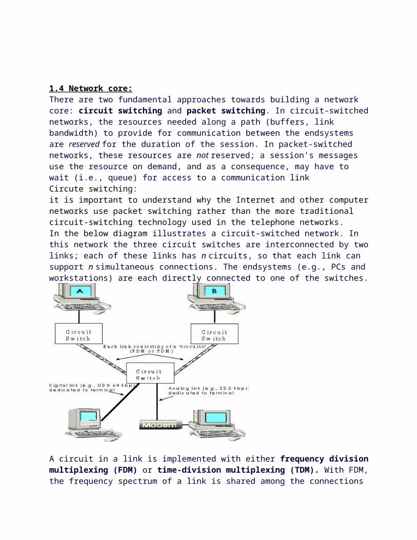
1.4 Network core:There are two fundamental approaches towards building a network core: circuit switching and packet switching. In circuit-switched networks, the resources needed along a path (buffers, link
bandwidth) to provide for communication between the endsystems are reserved for the duration of the session. In packet-switched networks, these resources are not reserved; a session's messages use the resource on demand, and as a consequence, may have to wait (i.e., queue) for access to a communication linkCircute switching:it is important to understand why the Internet and other computer networks use packet switching rather than the more traditional circuit-switching technology used in the telephone networks.In the below diagram illustrates a circuit-switched network. In this network the three circuit switches are interconnected by two links; each of these links has n circuits, so that each link can support n simultaneous connections. The endsystems (e.g., PCs and workstations) are each directly connected to one of the switches.
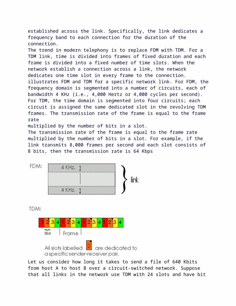
A circuit in a link is implemented with either frequency division multiplexing (FDM) or time-division multiplexing (TDM). With FDM, the frequency spectrum of a link is shared among the connections established across the link. Specifically, the link dedicates a frequency band to each connection for the duration of the connection.The trend in modern telephony is to replace FDM with TDM. For a TDM link, time is divided into frames of fixed duration and each frame is divided into a fixed number of time slots. When the network establish a connection across a link, the network dedicates one time slot in every frame to the connection.illustrates FDM and TDM for a specific network link. For FDM, the frequency domain is segmented into a number of circuits, each of bandwidth 4 KHz (i.e., 4,000 Hertz or 4,000 cycles per second). For TDM, the time domain is segmented into four circuits; each circuit is assigned the same dedicated slot in the revolving TDM frames. The transmission rate of the frame is equal to the frame ratemultiplied by the number of bits in a slot.
The transmission rate of the frame is equal to the frame rate multiplied by the number of bits in a slot. For example, if the link transmits 8,000 frames per second and each slot consists of 8 bits, then the transmission rate is 64 Kbps
Let us consider how long it takes to send a file of 640 Kbits from host A to host B over a circuit-switched network. Suppose that all links in the network use TDM with 24 slots and have bit rate 1.536 Mbps. Also suppose that it takes 500 msec to establish an end-to-end circuit before A can begin to transmit the file. How long does it take to send the file? Each circuit has a transmission rate of (1.536 Mbps)/24 = 64 Kbps, so it takes (640 Kbits)/(64 Kbps) = 10 seconds to transmit the filePacket switching:In modern packet-switched networks, the source breaks long messages into smaller packets. Between source and destination, each of these packets traverse communication links and packet switches (also known as routers). Packets aretransmitted over each communication link at a rate equal to the full transmission rate of the link. Most packet switches use store and forward transmission at the inputs to the links. Store-and-forward transmission means that the switch must receive the entire packet before it can begin to transmit the first bit of the packet onto the outbound linkThe output buffers play a key role in packet switching. If an arriving packet needs to be transmitted across a link but finds the link busy with the transmission of another packet, the arriving packet must wait in the output buffer addition to the store-and-forward delays, packets suffer output buffer queueing delays. These delays are variable and depend on the level of congestion in the network. Since the amount of buffer space is finite, an arriving packet may find that the buffer is completely filled with other packets waiting for transmission. In this case, packet loss will occur - either the arriving packet or one of the alreadyqueued packets will be dropped.
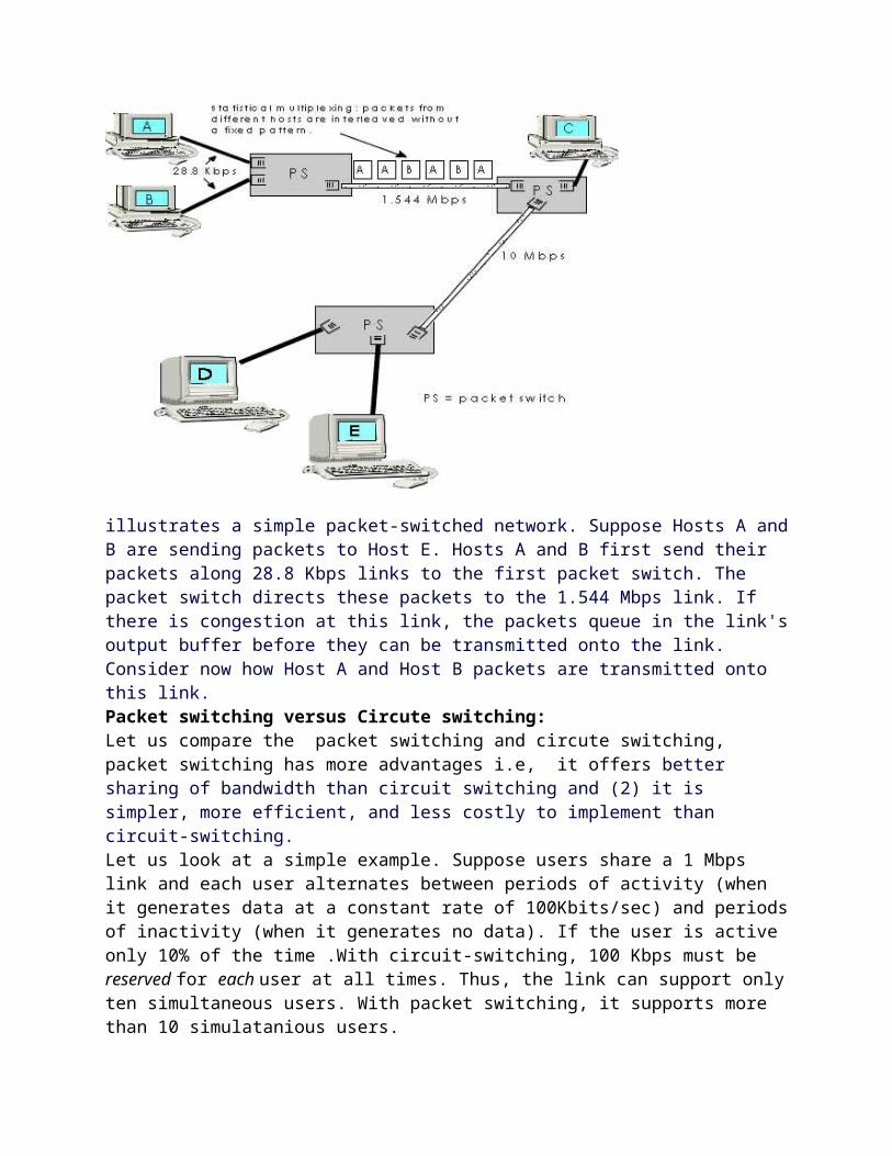
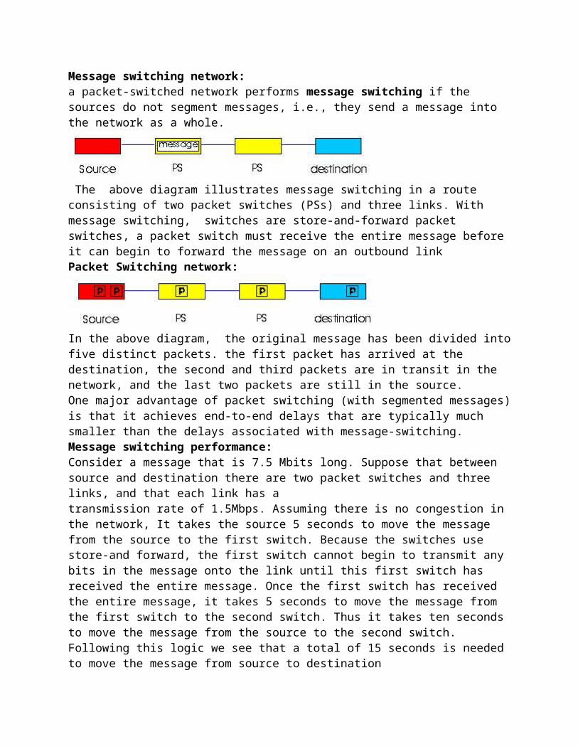
illustrates a simple packet-switched network. Suppose Hosts A and B are sending packets to Host E. Hosts A and B first send their packets along 28.8 Kbps links to the first packet switch. The packet switch directs these packets to the 1.544 Mbps link. If there is congestion at this link, the packets queue in the link's output buffer before they can be transmitted onto the link. Consider now how Host A and Host B packets are transmitted onto this link.Packet switching versus Circute switching:Let us compare the packet switching and circute switching, packet switching has more advantages i.e, it offers better sharing of bandwidth than circuit switching and (2) it is simpler, more efficient, and less costly to implement than circuit-switching.Let us look at a simple example. Suppose users share a 1 Mbps link and each user alternates between periods of activity (when it generates data at a constant rate of 100Kbits/sec) and periods of inactivity (when it generates no data). If the user is active only 10% of the time .With circuit-switching, 100 Kbps must be reserved for each user at all times. Thus, the link can support only ten simultaneous users. With packet switching, it supports more than 10 simulatanious users. Message switching network:a packet-switched network performs message switching if the sources do not segment messages, i.e., they send a message into the network as a whole.
The above diagram illustrates message switching in a route consisting of two packet switches (PSs) and three links. With message switching, switches are store-and-forward packet switches,
a packet switch must receive the entire message before it can begin to forward the message on an outbound linkPacket Switching network:
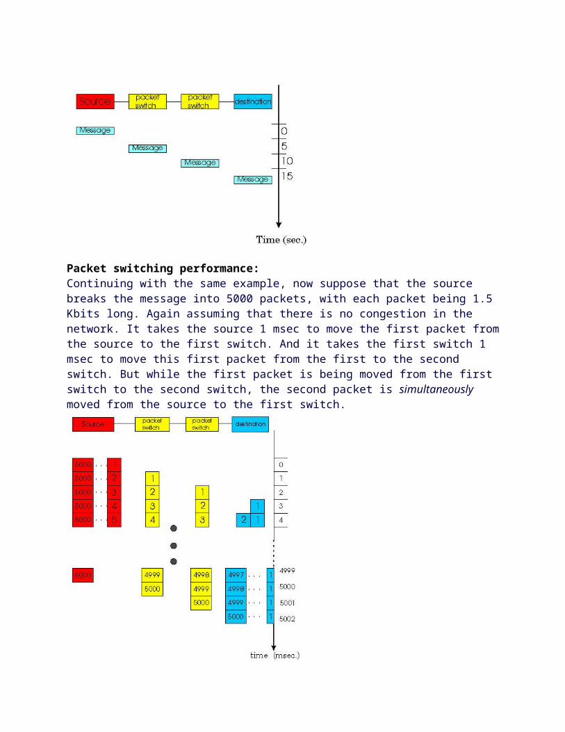
In the above diagram, the original message has been divided into five distinct packets. the first packet has arrived at the destination, the second and third packets are in transit in the network, and the last two packets are still in the source.One major advantage of packet switching (with segmented messages) is that it achieves end-to-end delays that are typically much smaller than the delays associated with message-switching.Message switching performance:Consider a message that is 7.5 Mbits long. Suppose that between source and destination there are two packet switches and three links, and that each link has atransmission rate of 1.5Mbps. Assuming there is no congestion in the network, It takes the source 5 seconds to move the message from the source to the first switch. Because the switches use store-and forward, the first switch cannot begin to transmit any bits in the message onto the link until this first switch has received the entire message. Once the first switch has received the entire message, it takes 5 seconds to move the message from the first switch to the second switch. Thus it takes ten seconds to move the message from the source to the second switch. Following this logic we see that a total of 15 seconds is needed to move the message from source to destination
Packet switching performance:Continuing with the same example, now suppose that the source breaks the message into 5000 packets, with each packet being 1.5 Kbits long. Again assuming that there is no congestion in the network. It takes the source 1 msec to move the first packet from the source to the first switch. And it takes the first switch 1 msec to move this first packet from the first to the second
switch. But while the first packet is being moved from the first switch to the second switch, the second packet is simultaneously moved from the source to the first switch.
message switching is performing sequential transmission whereas packet switching is performing parallel transmission. Observe that with message switching, while one node (the source or one of the switches) is transmitting, the remaining nodes are idle. With packet switching, once the first packet reaches the last switch, three nodes transmit at the same time.When a switch detects an error in a packet, it typically discards the entire packet. So, if the entire message is a packet and one bit in the message gets corrupted, the entire message is discarded. If, on the other hand, the message is segmented into many packets and one bit in one of the packets is corrupted, then only that one packet is discarded.
Routing in Data networks:
There are two broad classes of packet-switched networks: datagram networks and virtual-circuit networks. We shall call any network that routes packets according to host destination addresses a datagram network. The IP protocol of the Internet routes packets according to the destination addresses; hence the Internet is a datagram network. We shall call any network that routes packets according to virtual-circuit numbers a virtual-circuit network.
Virtual circuit network:
A virtual circuit (VC) consists of (1) a path (i.e., a series of links and packet switches) between the source and destination hosts, (2) virtual circuit numbers, one number for each link along the path, and (3) entries in VC-number translation tables in each packet switch along the path.
Once a VC is established between source and destination, packets can be sent with the appropriate VC numbers.Datagram Networks:In a datagram network, each packet contains the destination address in the hader , this address has a hierarchical structure. When a packet arrives at a packet switch in the network, each packet switch has a routing table which maps destination addresses to an outbound link.1.5 Access Networks and Physical Media:access network - the physical link(s) that connect an end system to its edge router, Access networks can be loosely divided into three categories:l residential access networks, connecting a home end system into the network;l institutional access networks, connecting an end system in a business or educational institution into the network;l mobile access networks, connecting a mobile end system into the networkResidential access network:A residential access network connects a home end system (typically a PC, but perhaps a Web TV or other residential system) to an edge router. Probably the most common form of home access is using a modem over a POTS (plain old telephone system) dialup line to an Internet service provider (ISP). The home modem converts the digital output of the PC into analog format for transmission over the analog phone line. A modem in the ISP converts the analog signal back into digital form for input to the ISP router. In this case, the "access network" is simply a point-to-point dialup link into an edge router However, due to the poor quality of twisted-pair line between many homes and ISPs, many users get an effective rate significantly less than 56 Kbps.narrowband ISDN technology (Integrated Services Digital Network) allows for all-digital transmission of data from a home end system over ISDN "telephone" lines to a phone company central office. that provides higher speed access (e.g., 128 Kbps) from the home into a data network such as the Internet.Asymmetric Digital Subscriber Line (ADSL) and hybrid fiber coaxial cable (HFC) are currently being deployed. ADSL is conceptually similar to dialup modems, but can transmit at rates of up to about 8 Mbps from the ISP router to a home end system. The data rate in the reverse direction, from the home end system to the central office router, is less than 1 Mbps. One of the features of ADSL is that the service allows the user to make an ordinary telephone call, using the POTs channel, while simultaneously surfing the Web
HFC access networks are extensions of the current cable network used for broadcasting cable television. Cable modems divide the HFC network into two channels, a downstream and an upstream channel. One important characteristic of the HFC is that it is a shared broadcast medium. In particular, every packet sent by the headend travels downstream on every link to every home; and every packet sent by a home travels on the upstream channel to the headend. Enterprise Access network:In enterprise access networks, a local area network (LAN) is used to connect an end system to an edge router there are many different types of LAN technology. However, Ethernet technology is currently by far the most prevalent access technology in enterprise networks. Ethernet operates 10 Mbps or 100Mbps (and now even at 1 Gbps). It uses either twisted-pair
copper wire are coaxial cable to connect a number of end systems with each other and with an edge router.Mobile Access NetworksMobile access networks use the radio spectrum to connect a mobile end system (e.g., a laptop PC or a PDA with a wireless modem) to a base station, An emerging standard for wireless data networking is Cellular Digital Packet Data (CDPD).
Physical media:In order to define "physical medium, let us reflect on the brief life of a bit The source end-system first transmits the bit and shortly thereafter the first router in the series receives the bit; the first router then transmits the bit and shortly afterwards the second router receives the bit, etc. the bit is sent by propagating electromagnetic waves across a physical medium Twisted-Pair Copper WireThe least-expensive and most commonly-used transmission medium is twisted-pair copper wire. Twisted pair consists of two insulated copper wires, each about 1 mm thick, arranged in a regular spiral pattern; The wires are twisted together to reduce the electrical interference from similar pairs close by. Typically, a number of pairs are bundled together in a cable by wrapping the pairs in a protective shield. A wire pair constitutes a single communication link.
Unshielded twisted pair
Unshielded twisted pair (UTP) is commonly used for computer networks within a building, that is, for local area networks (LANs). Data rates for LANs using twisted pair today range from 10 Mbps to 100 Mbps. The data rates that can be achieved depend on the thickness of the wire and the distance between transmitter and receiver
Coaxial-Cable
coaxial cable consists of two copper conductors, but the two conductors are concentric rather than parallel. With this construction and a special insulation and shielding, coaxial cable can have higher bit rates than twisted pair. Coaxial cable comes in two varieties: baseband coaxial cable and broadband coaxial cable.
Baseband coaxial cable, also called 50-ohm cable, is about a centimeter thick, lightweight, and easy to bend. It is commonly used in LANs; in fact, the computer you use at work or at school is probably connected to a LAN with either baseband coaxial cable or with UTP.
Broadband coaxial cable, also called 75-ohm cable, is quite a bit thicker, heavier, and stiffer than the baseband variety. Broadband cable, however, is quite common in cable television systems. Both baseband and broadband coaxial cable can be used as a guided shared medium.
Fiber Optics
An optical fiber is a thin, flexible medium that conducts pulses of light, with each pulse representing a bit. A single optical fiber can support tremendous bit rates, up to tens or even hundreds of gigabits per second These characteristics have made fiber optics the preferred long-haul guided transmission media, particularly for overseas links
Terrestrial and Satellite Radio Channels
Radio channels carry signals in the electromagnetic spectrum. They are an attractive media because require no physical "wire" to be installed, can penetrate walls, provide connectivity to a mobile user, and can potentially carry a signal for long distances.
Terrestrial radio channels can be broadly classified into two groups: those that operate as local area networks (typically spanning 10's to a few hundred meters) and wide-area radio channels that are used for mobile data services (typically operating within a metropolitan region).
1.6 Delay and Loss in packet Switched network:
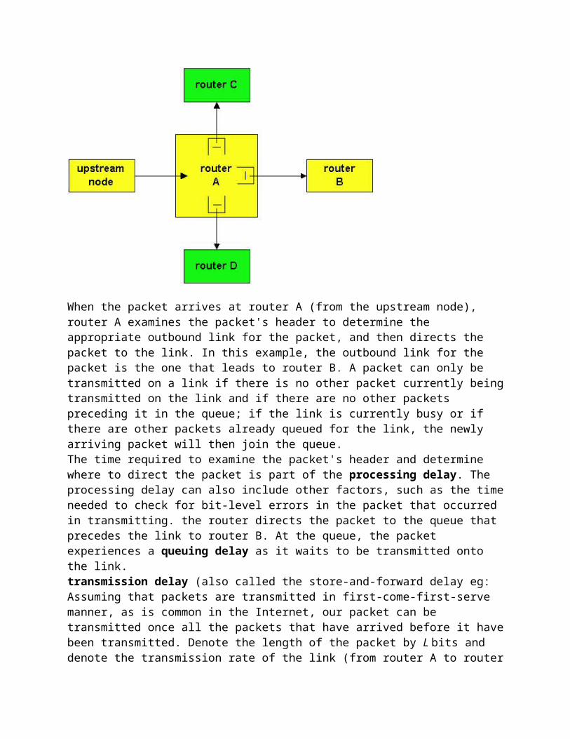
As a packet travels from one node (host or router) to the subsequent node (host or router) along this path, the packet suffers from several different types of delays at each node along the path. The most important of these delays are the nodal processing delay, queuing delay, transmission delay and propagation delay; together, these delays accumulate to give a total nodal delay.
When the packet arrives at router A (from the upstream node), router A examines the packet's header to determine the appropriate outbound link for the packet, and then directs the packet
to the link. In this example, the outbound link for the packet is the one that leads to router B. A packet can only be transmitted on a link if there is no other packet currently being transmitted on the link and if there are no other packets preceding it in the queue; if the link is currently busy or if there are other packets already queued for the link, the newly arriving packet will then join the queue.The time required to examine the packet's header and determine where to direct the packet is part of the processing delay. The processing delay can also include other factors, such as the time needed to check for bit-level errors in the packet that occurred in transmitting. the router directs the packet to the queue that precedes the link to router B. At the queue, the packet experiences a queuing delay as it waits to be transmitted onto the link.transmission delay (also called the store-and-forward delay eg: Assuming that packets are transmitted in first-come-first-serve manner, as is common in the Internet, our packet can be transmitted once all the packets that have arrived before it have been transmitted. Denote the length of the packet by L bits and denote the transmission rate of the link (from router A to router B) by R bits/sec. L/R. This is the amount of time required to transmit all of the packet's bits into the link.
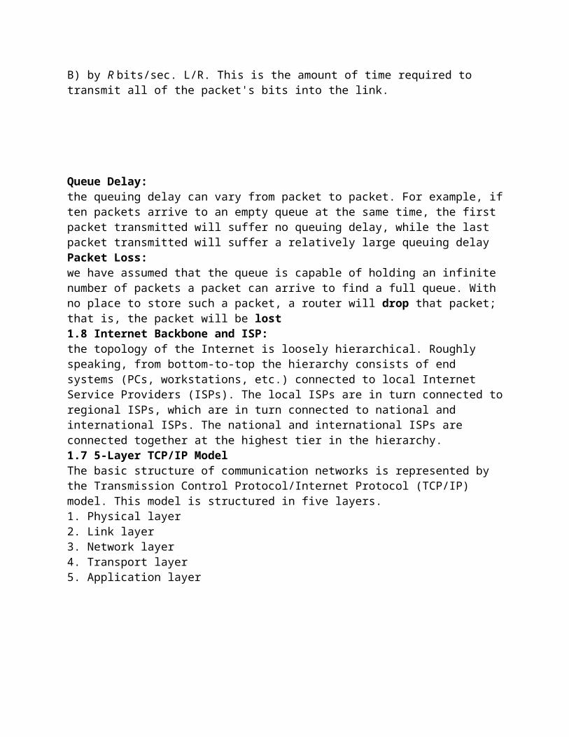
Queue Delay:the queuing delay can vary from packet to packet. For example, if ten packets arrive to an empty queue at the same time, the first packet transmitted will suffer no queuing delay, while the last packet transmitted will suffer a relatively large queuing delayPacket Loss:we have assumed that the queue is capable of holding an infinite number of packets a packet can arrive to find a full queue. With no place to store such a packet, a router will drop that packet; that is, the packet will be lost1.8 Internet Backbone and ISP:the topology of the Internet is loosely hierarchical. Roughly speaking, from bottom-to-top the hierarchy consists of end systems (PCs, workstations, etc.) connected to local Internet Service Providers (ISPs). The local ISPs are in turn connected to regional ISPs, which are in turn connected to national and international ISPs. The national and international ISPs are connected together at the highest tier in the hierarchy.1.7 5-Layer TCP/IP ModelThe basic structure of communication networks is represented by the Transmission Control Protocol/Internet Protocol (TCP/IP) model. This model is structured in five layers.1. Physical layer2. Link layer3. Network layer4. Transport layer5. Application layer
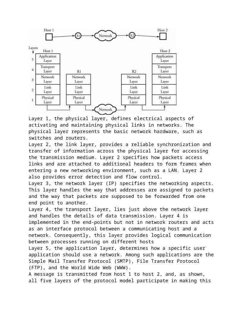
Layer 1, the physical layer, defines electrical aspects of activating and maintaining physical links in networks. The physical layer represents the basic network hardware, such as switches and routers.Layer 2, the link layer, provides a reliable synchronization and transfer of information across the physical layer for accessing the transmission medium. Layer 2 specifies how packets access links and are attached to additional headers to form frames when entering a new networking environment, such as a LAN. Layer 2 also provides error detection and flow control.Layer 3, the network layer (IP) specifies the networking aspects. This layer handles the way that addresses are assigned to packets and the way that packets are supposed to be forwarded from one end point to another. Layer 4, the transport layer, lies just above the network layer and handles the details of data transmission. Layer 4 is implemented in the end-points but not in network routers and acts as an interface protocol between a communicating host and a network. Consequently, this layer provides logical communication between processes running on different hostsLayer 5, the application layer, determines how a specific user application should use a network. Among such applications are the Simple Mail Transfer Protocol (SMTP), File Transfer Protocol (FTP), and the World Wide Web (WWW).A message is transmitted from host 1 to host 2, and, as shown, all five layers of the protocol model participate in making this connection. The data being transmitted from host 1 is passed down through all five layers to reach router R1. Router R1 is located as a gateway to the operating regions of host 1 and therefore does not involve any tasks in layers 4 and 5. The same scenario is applied at the other end: router R2. Similarly, router R2, acting as a gateway to the operating regions of host 2, does not involve any tasks in layers 4 and 5. Finally at host 2, the data is transmitted upward from the physical layer to the application layer.
1.8 Internet Protocols and Addressing
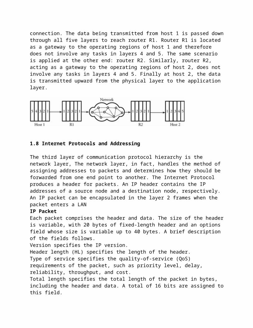
The third layer of communication protocol hierarchy is the network layer, The network layer, in fact, handles the method of assigning addresses to packets and determines how they should be forwarded from one end point to another. The Internet Protocol produces a header for packets. An IP header contains the IP addresses of a source node and a destination node, respectively. An IP packet can be encapsulated in the layer 2 frames when the packet enters a LANIP PacketEach packet comprises the header and data. The size of the header is variable, with 20 bytes of fixed-length header and an options field whose size is variable up to 40 bytes. A brief description of the fields follows.Version specifies the IP version.Header length (HL) specifies the length of the header.Type of service specifies the quality-of-service (QoS) requirements of the packet, such as priority level, delay, reliability, throughput, and cost.Total length specifies the total length of the packet in bytes, including the header and data. A total of 16 bits are assigned to this field.Identification, flags, and fragment offset are used for packet fragmentation and reassembly.Time to live specifies the maximum number of hops after which a packet must be discarded.Protocol specifies the protocol used at the destination.Header checksum is a method of error detection Source address and destination address are 32-bit fields specifying the source address and thedestination address, respectively.Options is a rarely used variable-length field to specify security level, timestamp, and type of route.Padding is used to ensure that the header is a multiple of 32 bits.
IP Addressing SchemeAn IP address is a unique identifier used to locate a device on the IP network. To make the system scalable, the address structure is subdivided into the network ID and the host ID. The
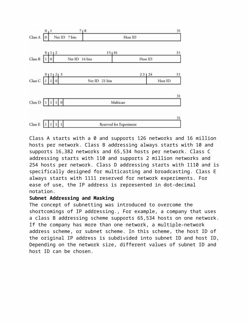
network ID identifies the network the device belongs to; the host ID identifies the device.Based on the bit positioning assigned to the network ID and the host ID, the IP address is further subdivided into classes A, B, C, D (multicast), and E (reserved),
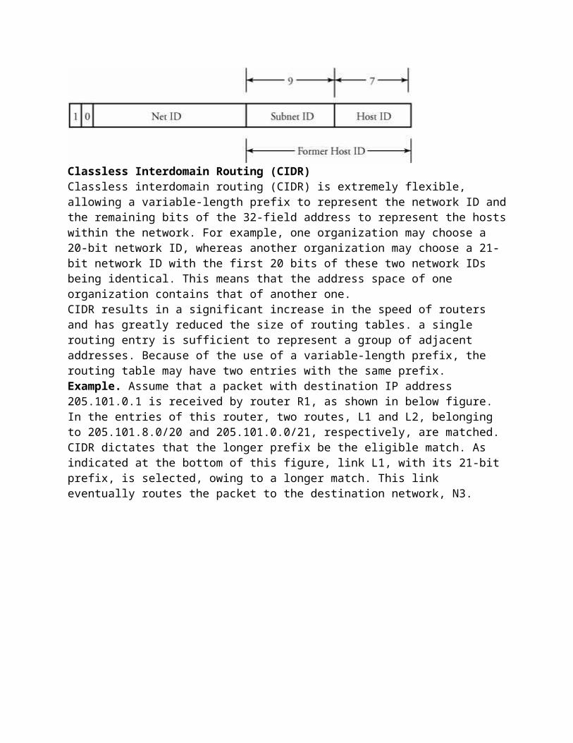
Class A starts with a 0 and supports 126 networks and 16 million hosts per network. Class B addressing always starts with 10 and supports 16,382 networks and 65,534 hosts per network. Class C addressing starts with 110 and supports 2 million networks and 254 hosts per network. Class D addressing starts with 1110 and is specifically designed for multicasting and broadcasting. Class E always starts with 1111 reserved for network experiments. For ease of use, the IP address is represented in dot-decimal notation.Subnet Addressing and MaskingThe concept of subnetting was introduced to overcome the shortcomings of IP addressing., For example, a company that uses a class B addressing scheme supports 65,534 hosts on one network. If the company has more than one network, a multiple-network address scheme, or subnet scheme. In this scheme, the host ID of the original IP address is subdivided into subnet ID and host ID, Depending on the network size, different values of subnet ID and host ID can be chosen.
Classless Interdomain Routing (CIDR)
Classless interdomain routing (CIDR) is extremely flexible, allowing a variable-length prefix to represent the network ID and the remaining bits of the 32-field address to represent the hosts within the network. For example, one organization may choose a 20-bit network ID, whereas another organization may choose a 21-bit network ID with the first 20 bits of these two network IDs being identical. This means that the address space of one organization contains that of another one.CIDR results in a significant increase in the speed of routers and has greatly reduced the size of routing tables. a single routing entry is sufficient to represent a group of adjacent addresses. Because of the use of a variable-length prefix, the routing table may have two entries with the same prefix.Example. Assume that a packet with destination IP address 205.101.0.1 is received by router R1, as shown in below figure. In the entries of this router, two routes, L1 and L2, belonging to 205.101.8.0/20 and 205.101.0.0/21, respectively, are matched. CIDR dictates that the longer prefix be the eligible match. As indicated at the bottom of this figure, link L1, with its 21-bit prefix, is selected, owing to a longer match. This link eventually routes the packet to the destination network, N3.
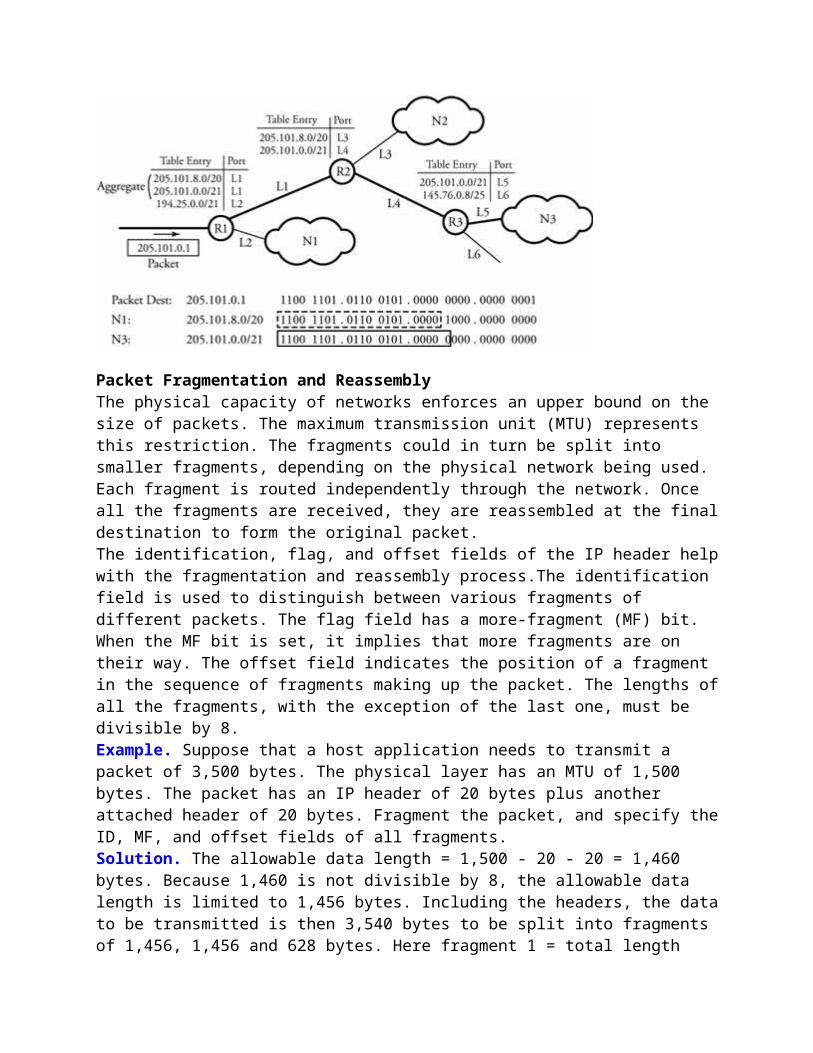
Packet Fragmentation and ReassemblyThe physical capacity of networks enforces an upper bound on the size of packets. The maximum transmission unit (MTU) represents this restriction. The fragments could in turn be split into smaller fragments, depending on the physical network being used. Each fragment is routed independently through the network. Once all the fragments are received, they are reassembled at the final destination to form the original packet.The identification, flag, and offset fields of the IP header help with the fragmentation and reassembly process.The identification field is used to distinguish between various fragments of different packets. The flag field has a more-fragment (MF) bit. When the MF bit is set, it implies that more fragments are on their way. The offset field indicates the position of a fragment in the sequence of fragments making up the packet. The lengths of all the fragments, with the exception of the last one, must be divisible by 8.Example. Suppose that a host application needs to transmit a packet of 3,500 bytes. The physical layer has an MTU of 1,500 bytes. The packet has an IP header of 20 bytes plus another
attached header of 20 bytes. Fragment the packet, and specify the ID, MF, and offset fields of all fragments.Solution. The allowable data length = 1,500 - 20 - 20 = 1,460 bytes. Because 1,460 is not divisible by 8, the allowable data length is limited to 1,456 bytes. Including the headers, the data to be transmitted is then 3,540 bytes to be split into fragments of 1,456, 1,456 and 628 bytes. Here fragment 1 = total length 1,456, MF 1, offset 0; fragment 2 = total length 1,456, MF 1, offset 182; and fragment 3 = total length 628, MF 0, and offset 364.
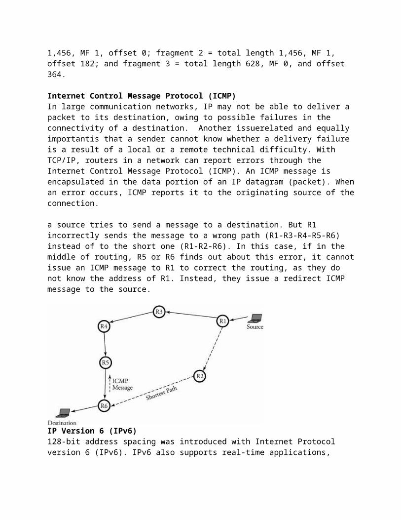
Internet Control Message Protocol (ICMP)In large communication networks, IP may not be able to deliver a packet to its destination, owing to possible failures in the connectivity of a destination. Another issuerelated and equally importantis that a sender cannot know whether a delivery failure is a result of a local or a remote technical difficulty. With TCP/IP, routers in a network can report errors through the Internet Control Message Protocol (ICMP). An ICMP message is encapsulated in the data portion of an IP datagram (packet). When an error occurs, ICMP reports it to the originating source of the connection.
a source tries to send a message to a destination. But R1 incorrectly sends the message to a wrong path (R1-R3-R4-R5-R6) instead of to the short one (R1-R2-R6). In this case, if in the middle of routing, R5 or R6 finds out about this error, it cannot issue an ICMP message to R1 to correct the routing, as they do not know the address of R1. Instead, they issue a redirect ICMP message to the source.
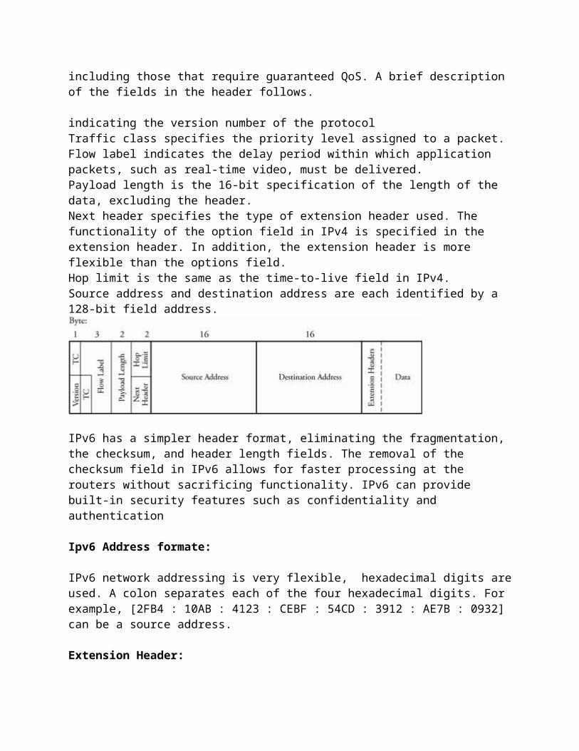
IP Version 6 (IPv6)128-bit address spacing was introduced with Internet Protocol version 6 (IPv6). IPv6 also supports real-time applications, including those that require guaranteed QoS. A brief description of the fields in the header follows.
indicating the version number of the protocolTraffic class specifies the priority level assigned to a packet.
Flow label indicates the delay period within which application packets, such as real-time video, must be delivered.Payload length is the 16-bit specification of the length of the data, excluding the header.Next header specifies the type of extension header used. The functionality of the option field in IPv4 is specified in the extension header. In addition, the extension header is more flexible than the options field.Hop limit is the same as the time-to-live field in IPv4.Source address and destination address are each identified by a 128-bit field address.
IPv6 has a simpler header format, eliminating the fragmentation, the checksum, and header length fields. The removal of the checksum field in IPv6 allows for faster processing at the routers without sacrificing functionality. IPv6 can provide built-in security features such as confidentiality and authentication
Ipv6 Address formate:
IPv6 network addressing is very flexible, hexadecimal digits are used. A colon separates each of the four hexadecimal digits. For example, [2FB4 : 10AB : 4123 : CEBF : 54CD : 3912 : AE7B : 0932] can be a source address.
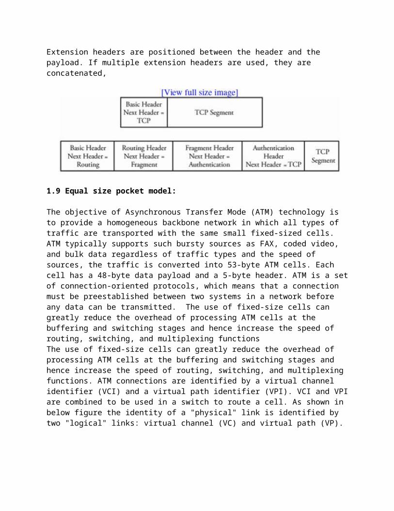
Extension Header:
Extension headers are positioned between the header and the payload. If multiple extension headers are used, they are concatenated,
1.9 Equal size pocket model:
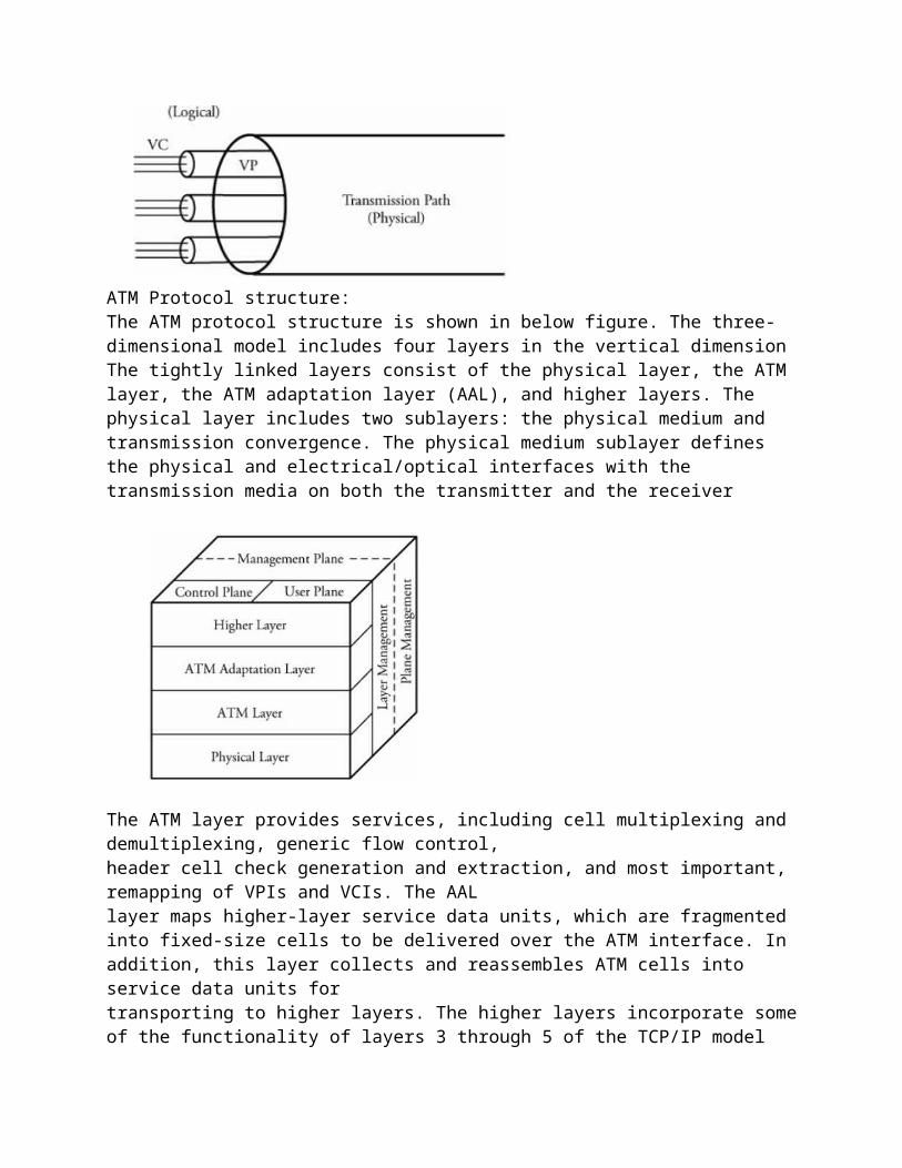
The objective of Asynchronous Transfer Mode (ATM) technology is to provide a homogeneous backbone network in which all types of traffic are transported with the same small fixed-sized cells. ATM typically supports such bursty sources as FAX, coded video, and bulk data regardless of traffic types and the speed of sources, the traffic is converted into 53-byte ATM cells. Each cell has a 48-byte data payload and a 5-byte header. ATM is a set of connection-oriented protocols, which means that a connection must be preestablished between two systems in a network before any data can be transmitted. The use of fixed-size cells can greatly reduce the overhead of processing ATM cells at the buffering and switching stages and hence increase the speed of routing, switching, and multiplexing functionsThe use of fixed-size cells can greatly reduce the overhead of processing ATM cells at the buffering and switching stages and hence increase the speed of routing, switching, and multiplexing functions. ATM connections are identified by a virtual channel identifier (VCI) and a virtual path identifier (VPI). VCI and VPI are combined to be used in a switch to route a cell. As shown in below figure the identity of a "physical" link is identified by two "logical" links: virtual channel (VC) and virtual path (VP).
ATM Protocol structure:The ATM protocol structure is shown in below figure. The three-dimensional model includes four layers in the vertical dimension The tightly linked layers consist of the physical layer, the ATM layer, the ATM adaptation layer (AAL), and higher layers. The physical layer includes two sublayers: the physical medium and transmission convergence. The physical medium sublayer defines the physical and electrical/optical interfaces with the transmission media on both the transmitter and the receiver
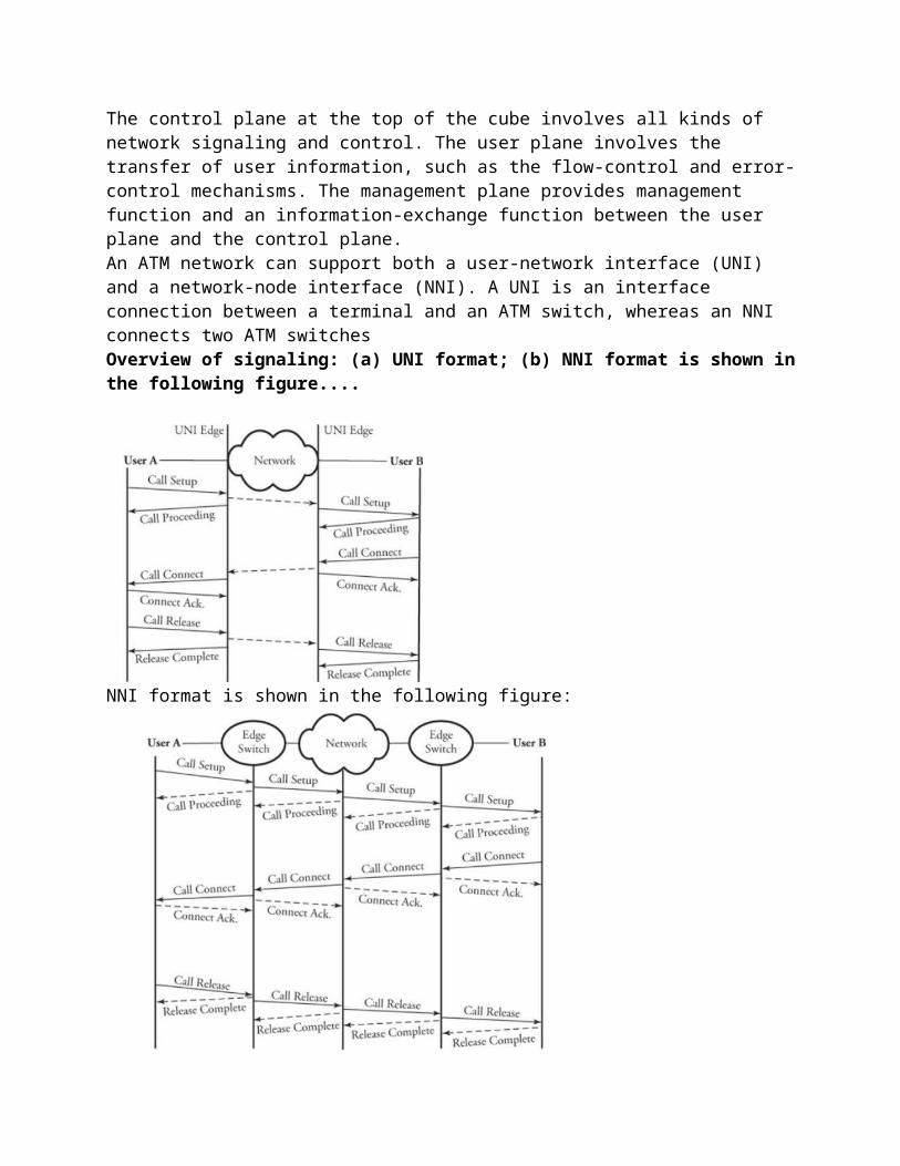
The ATM layer provides services, including cell multiplexing and demultiplexing, generic flow control,header cell check generation and extraction, and most important, remapping of VPIs and VCIs. The AALlayer maps higher-layer service data units, which are fragmented into fixed-size cells to be delivered over the ATM interface. In addition, this layer collects and reassembles ATM cells into service data units fortransporting to higher layers. The higher layers incorporate some of the functionality of layers 3 through 5 of the TCP/IP modelThe control plane at the top of the cube involves all kinds of network signaling and control. The user plane involves the transfer of user information, such as the flow-control and error-control mechanisms. The management plane provides management function and an information-exchange function between the user plane and the control plane.An ATM network can support both a user-network interface (UNI) and a network-node interface (NNI). A UNI is an interface connection between a terminal and an ATM switch, whereas an NNI connects two ATM switchesOverview of signaling: (a) UNI format; (b) NNI format is shown in the following figure....
NNI format is shown in the following figure:
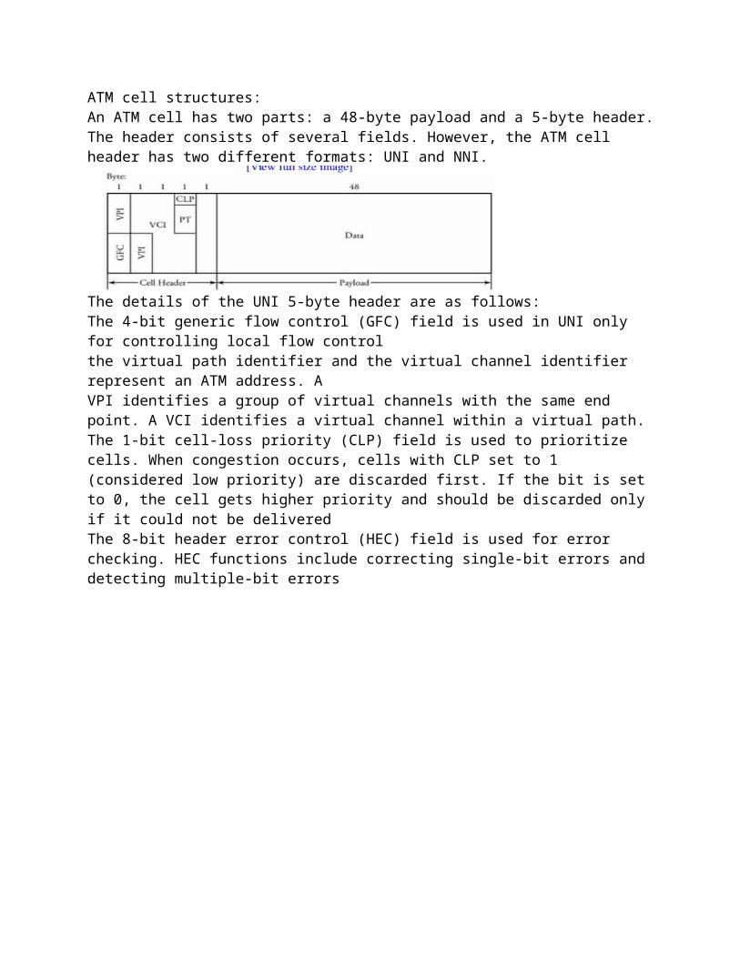
ATM cell structures:An ATM cell has two parts: a 48-byte payload and a 5-byte header. The header consists of several fields. However, the ATM cell header has two different formats: UNI and NNI.
The details of the UNI 5-byte header are as follows:The 4-bit generic flow control (GFC) field is used in UNI only for controlling local flow controlthe virtual path identifier and the virtual channel identifier represent an ATM address. AVPI identifies a group of virtual channels with the same end point. A VCI identifies a virtual channel within a virtual path.The 1-bit cell-loss priority (CLP) field is used to prioritize cells. When congestion occurs, cells with CLP set to 1 (considered low priority) are discarded first. If the bit is set to 0, the cell gets higher priority and should be discarded only if it could not be deliveredThe 8-bit header error control (HEC) field is used for error checking. HEC functions include correcting single-bit errors and detecting multiple-bit errors
Unit –II2.1 Multiplexers:multiplexing is a technique that allows many communication sources to transmit data over a single physical line. Multiplexers are used in a network for maximum transmission capacity of a high-bandwidth line. Multiplexing schemes can be divided into three basic categories:frequency-division multiplexing, wavelength-division multiplexing, time-division multiplexingFrequency Division Multiplexing: (FDM) :In frequency-division multiplexing (FDM), the frequency spectrum is divided into frequency bands, or channels, in which each user can be assigned a band. the following figure shows how n frequency channels are multiplexed using FDM.
any two adjacent channels have some overlap because channel spectra do not have sharp edges. This overlap normally creates spike noise at the edge of each channel. FDM is normally used over copper wires or microwave channels and is suitable for analog circuitry.Wavelength Division multiplexing (WDM):Wavelength-division multiplexing (WDM) is fundamentally the same as FDM, WDM was invented as a variation of frequency-division multiplexing and is basically a multiplexing method of different wavelengths instead of frequencies. In the figure, n optical fibers come together at an optical multiplexer, each with its energy present at a different wavelength. The n optic lines are combined onto a single shared link for transmission to a distant destination.
n optical fibers come together at an optical multiplexer, each with its energy present at a different wavelength instead of frequenciesTime Division Multiplex:With a time-division multiplexing (TDM), users take turns in a predefined fashion, each one periodicallygetting the entire bandwidth for a portion of the total scanning time. Given n inputs, time is divided intoframes, and each frame is further subdivided into time slots, or channels. Each channel is allocated to oneinput. Packets arrive on n lines, and the multiplexer scans them, forming a frame with n channels on its outgoing link.
Synchronous Time Division Multiplex:
In synchronous TDM, the multiplexer scans all lines without exception. The scanning time for each line isPreallocated. the scanner should stay on that line, whether or not there is data for scanning within that time slot. Once a synchronous multiplexer is programmed to produce same-sized frames, the lack of data in any channel potentially creates changes to average bit rate on the ongoing link
Statistical TDM:
a frame's time slots are dynamically allocated, based on demand. This method removes all the empty slots on a frame and makes the multiplexer operate more efficiently. Consider a multiplexer with n available channels. If the number of requesting input sources, m, is greater than n channels, the multiplexer typically reacts by clipping, whereby unassigned sources are partially transmitted, or clipped.
2.2 Modems and Internet Access Devices:
Users access the Internet from residential areas primarily through modems. A modem is a device that converts the digital data to a modulated form of signal that takes less bandwidth. A user can access the Internet by using either the existing telephone link infrastructure or the existing cable TV infrastructure.
Two commonly used modems are the digital subscriber line (DSL) modem and the cable modem
Line Coding Methods:
Before processing a raw signal for modulation, a line coding process is performed on binary signals for digital transmission. With line coding, a binary information sequence is converted into a digital code. This process is required to maximize bit rate in digital transmission.
the cost and complexity are the main factor in the selection of encoder. Encoded signals are produced by the line codes for the binary sequence 1011 0100 1110 0010 are shown in the following figure.
The simplest form of line coding is the natural nonreturn-to-zero (NRZ) where a binary 1 is represented by a +V voltage level, and a 0 is represented by a 0 voltage. A more power-efficient line coding method is known as polar NRZ. In this method, a binary 1 is mapped to +V/2 and a binary 0 is represented by -V/2.
NRZ-inverted coding, the binary information is mapped into transitions at the beginning of each interval so that a binary 1 is converted to a transition at the beginning of a bit time and a 0 having no transition.
With the Manchester encoding method, a binary 1 is represented by a 1 plus a transition to 0 and then a 0; and a binary 0 is represented by a 0 plus a transition to 1 and then a 1. A great feature of the Manchester encoding is that it is self-clocking
Digital Modulation Techniques:
In order to reduce the bandwidth of digital signals, digital modulation technique is required before any transmission. the following types of modulation techniques:
Amplitude shift keying (ASK)Frequency shift keying (FSK)Phase shift keying (PSK)Quadrature amplitude modulation (QAM)
Digital Subscriber Line (DSL) Modems:
Digital subscriber line (DSL) technology is a convenient option for home users to access the Internet. This technology offers various versions of DSL technology: ADSL, VDSL, HDSL, and SDSL, or, in general, xDSL.
asymmetric DSL (ADSL) is popular and is designed for residential users. A modem is designed to be connected to telephone links. These links are capable of handling bandwidths up to 1.1 MHz. Out of this bandwidth, only 4 KHz are used for a phone conversation. the remaining bandwidth can become available to be allocated to data communications
The standard modulation technique for ADSL is QAM. The available bandwidth of 1.1 MHz is divided into 256 channels, each using abandwidth of approximately 4.312 KHz. Voice communication uses channel 0. Channels 15 remain idle andtogether act as a guard band between voice and data communication. Because data communication bandwidth is split into two bandwidthsupstream for communications from the user to the Internet and downstream for communications from the Internet to the user the technique is said to be asymmetric.
The details of spectrum division for an ADSL modem are shown in below diagram
Another type of DSL technique is symmetric digital subscriber line (SDSL). This technique divides theavailable bandwidth equally between downstream and upstream data transfer.
Very high bit-rate digital subscriber line (VDSL) is similar to ADSL but uses coaxial or fiber-optic cable for a bit rate of 50 Mb/s to 55 Mb/s downstream and 1.5 Mb/s to 2.5 Mb/s upstream data transfer.
High-bit-rate digital subscriber line (HDSL), as another option, was designed to compete with T-l lines, HDSL uses two twisted-pair wires and 2B1Q, an encoding technique less susceptible to attenuationHDSL can achieve a data rate of 2 Mb/s without needing repeaters for up to 3.6 km.
Cable Modems:
A cable company lays out very high-speed backbone optical fiber cables all the way to the residentialbuildings, each of which can then be connected to the optical infrastructure for TV, radio, and the Internetthrough either a coaxial (coax) cable or optical fiber, depending on its demand and budget. This network is called hybrid fiber-coaxial (HFC). Video signals are transmitted downstream from headquarters to users. Communication in an HFC cable TV network is bidirectional.
The cable company divides the bandwidth into video/radio, downstream data, and upstream data. Coaxial cables can carry signals up to 750 MHz.
About 500 MHz of this bandwidth is assigned to TV channels. As the bandwidth of each TV channel is 6 MHz, the assigned bandwidth can accommodate more than 80 channels. Some technical methods allow
this number to increase to 180 TV channels. About 200 MHz of the coax bandwidth, from 550 MHz to 750 MHz, is allocated to the downstream data transfer: from the Internet side to a user.This bandwidth is also divided to about 33 channels, each with 6 MHz bandwidth. The cable modem uses the 64-QAM or 256-QAM modulation technique for the downstream data transfer.
The upstream data premises communicate to the Internet and occupy 37 MHz, from 5 MHz to 42 MHz,including 6 MHz-wide channels. The upstream data is modulated using the QPSK (Quadrature PSK)technique
2.3 Switching and Routing Devices:
Switching devices are categorized by their complexity, as follows:
Layers 1 and 2 switches are typically simple. For example, repeaters and hubs are known as layer switches; bridges, as layer 2 switches. Layer 3 or higher switches are complex. Routers, for example, are layer 3 switches
Repeaters and hubs, the simplest switching devices, are designed primarily to interconnect very small LAN units without any involvement in the complex routing processes
Repeaters are used to connect two segments of a LAN. A repeater's essential function, signal egeneration, differentiates it from a piece of cable. Signal regeneration is needed when the LAN length is extended.
A hub is another simple device and is used to provide connections among multiple users in layer 1 of aprotocol stack. A hub is similar to the repeater but connects several pieces of a LAN. a hub is amultipoint repeater. A bridge is a switch that connects two pieces of a LAN or two LANs, especially those operating in layer 2 of the protocol stack. However, a bridge can also be used in layer 1 for signal regeneration. As it operates at layer 2, a bridge does more than simply extend the range of the network. A bridge checks the physical address of any destination user and enhances the efficiency of networks by facilitating simultaneous transmissions within multiple LANs. a bridge does not forward a frame to all LAN users and thus can isolate traffic between two LANs.
Routers and Higher-Layer Switches
A router is a layer 3 switch that connects other routing nodes, router is dependent on protocols and establishes physical circuits for individual node-pair connection. A router has a routing look-up table for routing packets. If a communication is connectionless, packets of a message are sent individually but not in order.
Layer 3 switches are of two types:
Packet-by-packet switches, by which packet forwarding is handled based on each individual packet.Flow-based switches, by which a number of packets having the same source and destination areidentified and forwarded together. This scheme speeds up the forwarding process.
2.4 Router Structure:
Routers are the building blocks of wide area networks, Packets arrive at n input ports and are routed out from n output ports. The system consists of four main parts: input port processors, output port processors, switch fabric (switching network), and switch controller.
Input Port Processor (IPP)
Input and output port processors, as interfaces to switch fabric, are commercially implemented together in router line cards, which contain some of the task of the physical and data link layers. The
functionality of the data link layer is implemented as a separate chip in IPP, which also provides a buffer to match the speed between the input and the switch fabric.
An input port processor (IPP) typically consists of several main modules, as shown in following figure. These modules are packet fragmentation, main buffer, multicast process, routing table, packet encapsulator, and a comprehensive QoS
Packet Fragmentation
The packet fragmentation unit, converts packets to smaller sizes. Large packets cause different issues at the network and link layers. when large packets must be buffered at the input port interface of a router, as buffer slots are usually only 512 bytes long. One solution to this problem is to partition packets into smaller fragments and then reassemble them at the output port processor (OPP) after processing them in the switching system
Routing Table:
The routing table is a look-up table containing all available destination addresses and the correspondingswitch output port.