Embed Size (px)
Citation preview
621
26
ON-BOARD DIAGNOSTICS
During the 1980s, many manufacturers beganequipping their vehicles with full-function controlsystems capable of alerting the driver of a malfunc-tion and of allowing the technician to retrieve codesthat identify circuit faults. These early diagnosticsystems were meant to reduce emissions and assistthe technician. The automotive industry calls thesesystems on-board diagnostics (OBD).
On-Board Diagnostics:Early Systems
The powertrain control module (PCM) has a built-inself-diagnosis program that detects failures or majorfaults in the engine management system and alertsthe driver by illuminating a Malfunction IndicatorLamp (MIL). The MIL informs the driver to “CheckEngine,” “Service Engine Soon,” or “Power Loss.” SeeFigure 26–1.
The lamp will stay on if the problem is present(hard fault) and will go out if the problem no longerexists (soft fault). A fault code will set and remain incomputer memory for approximately 25 to 30 enginestarts (most vehicles).This is an aid to the technicianwhen diagnosing the system.
Computers and On-Board Diagnostics
OBJECTIVES: After studying Chapter 26, you shouldbe able to:
1. Prepare for the interprovincial Red Seal certificationexamination in Appendix VIII (Engine Performance)on the topics covered in this chapter.
2. Explain the purpose, function and operation of "flash"codes.
3. Describe the diagnostic procedures and routinesrelating to a trouble code.
4. Explain the purpose and operation of a scan tool.5. Describe the differences between OBD I and OBD II.6. Describe how the powertrain control module
performs active and passive tests of thecomputerized engine control system.
7. Describe the standardized OBD II DTCs andterminology.
8. Explain the purpose behind one- and two-trip logic.
Figure 26–1 A typical malfunction indicator lamp (MIL),often labelled “Check Engine” or “Service Engine Soon.”
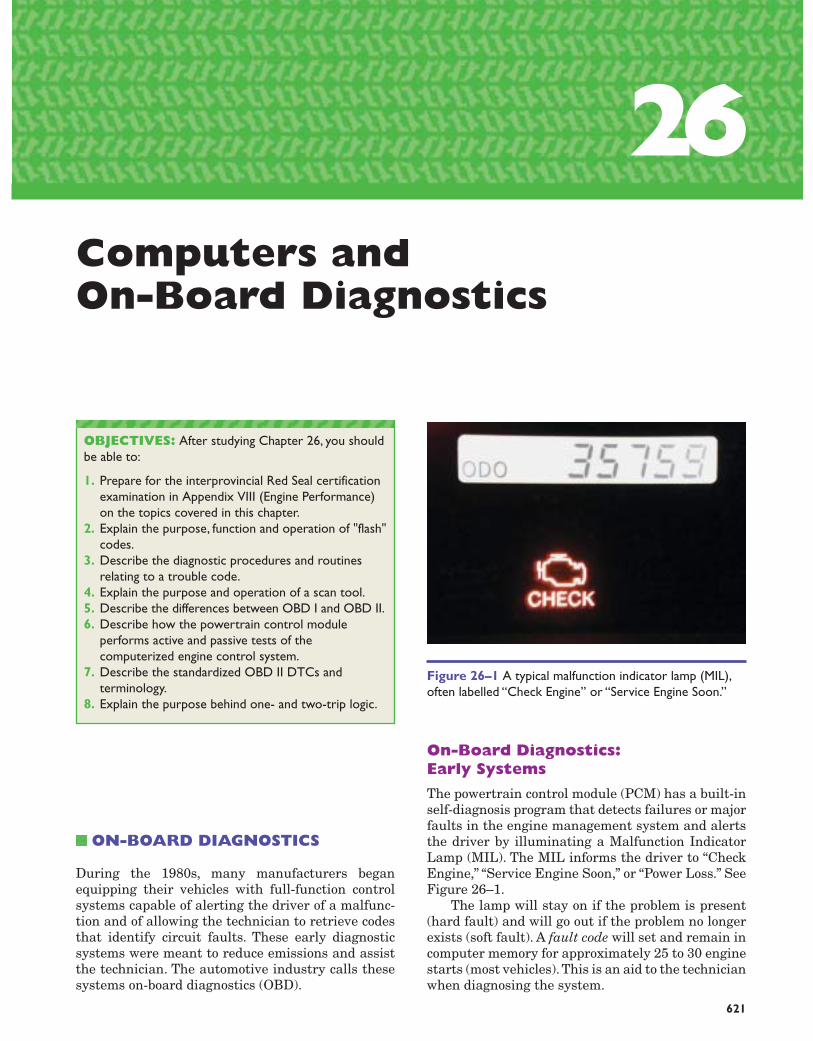
Fault codes (diagnostic trouble codes—DTCs)are accessed through a diagnostic (data link connec-tor—DLC) found in many different locations, e.g.,under the hood, under the dash, in the console or theglove box. Often, the shop manual must be consultedfor the exact location. See Figure 26–2. The DLC alsovaries in appearance among makes.
Flash Codes
The procedures for retrieving DTCs differs amongmakes. Many on-board computer diagnostics are en-tered by connecting two or more terminals in the DLCwith a jumper (GM and many imports); see Figure26–3. Chrysler cycles the ignition key a given numberof times within 5 seconds. This will activate the MIL,which begins to flash; count the number of flashes.
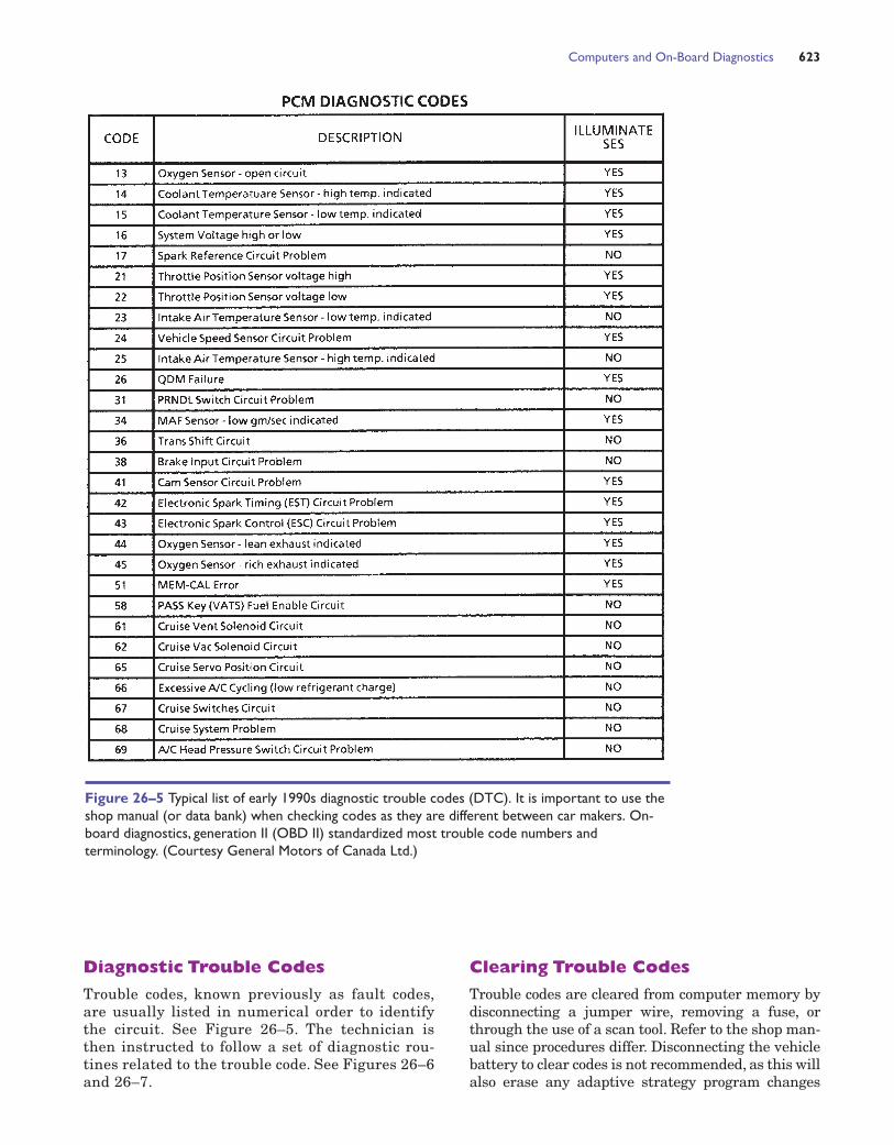
Voltmeters are used with some Ford and Mit-subishi vehicles to identify trouble codes. Connectinga voltmeter into the system, as shown in Figure 26–4,will cause the meter needle to rise and fall; countingthe number of needle sweeps will identify the DTC.Ford vehicles also go through a self-test, whichchecks the sensors and actuators before giving outtrouble codes.
622 CHAPTER 26
Figure 26–2 The data link connector (DLC) is locatedunder the dash on this General Motors vehicle. It is knownas the assembly-line communications link (ALCL) on earlyGM vehicles because it allowed the assembly plant to testengine operations before the vehicle left the factory. It isused by service technicians in the field to access troublecodes and read live data stream. (Courtesy GeneralMotors of Canada Ltd.)
Figure 26–3 The data link connector on many Asian anddomestic vehicles (non–OBD II) will cause the malfunctionindicator lamp to flash trouble codes when the designatedterminals are connected with a jumper wire. (CourtesyToyota Canada Inc.)
Figure 26–4 Analog voltmeters are used by Ford andsome import vehicles to read diagnostic trouble codes.Counting the number of needle sweeps (pulses) willdetermine the code. (Courtesy Ford Motor Co. ofCanada Ltd.)
Computers and On-Board Diagnostics 623
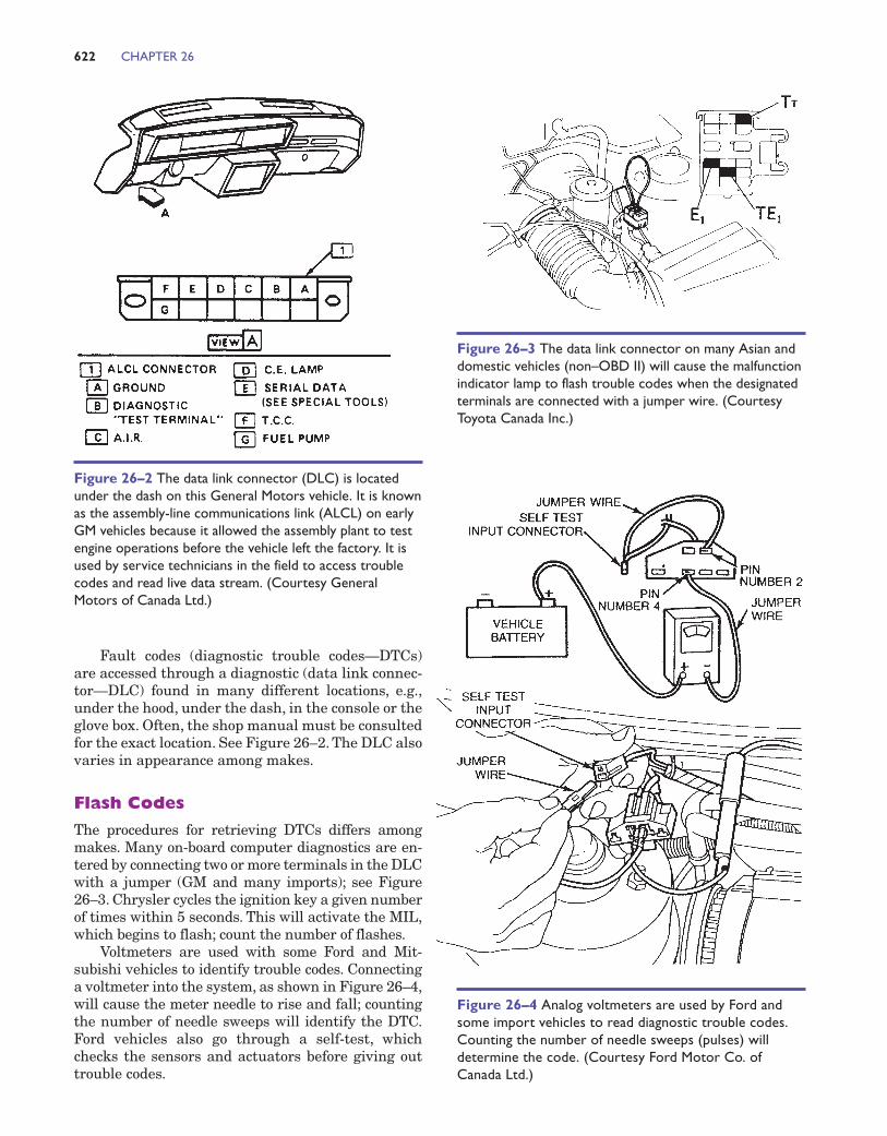
Figure 26–5 Typical list of early 1990s diagnostic trouble codes (DTC). It is important to use theshop manual (or data bank) when checking codes as they are different between car makers. On-board diagnostics, generation II (OBD II) standardized most trouble code numbers andterminology. (Courtesy General Motors of Canada Ltd.)
Diagnostic Trouble Codes
Trouble codes, known previously as fault codes,are usually listed in numerical order to identifythe circuit. See Figure 26–5. The technician isthen instructed to follow a set of diagnostic rou-tines related to the trouble code. See Figures 26–6and 26–7.
Clearing Trouble Codes
Trouble codes are cleared from computer memory bydisconnecting a jumper wire, removing a fuse, orthrough the use of a scan tool. Refer to the shop man-ual since procedures differ. Disconnecting the vehiclebattery to clear codes is not recommended, as this willalso erase any adaptive strategy program changes
stored in the computer. Other components such as theradio, which uses battery power to retain memory, willalso lose their settings.
Scan Tools
Scanners are small hand-held computers that pro-vide a major improvement over flash-code diagnos-tics. They typically plug into the data link connector
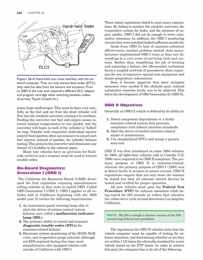
and interface with the on-board computer. Power tooperate the scanner is supplied through the lightersocket or a battery adaptor; late-model OBD II scan-ners receive power at the DLC. See Figure 26–8.
Scanners have the ability to read directly from livedata stream; information from the input sensors andoutput actuators may be monitored during a road test.Many scan tools have a snap-shot mode, which allowsthe technician to freeze certain data at the point the
624 CHAPTER 26
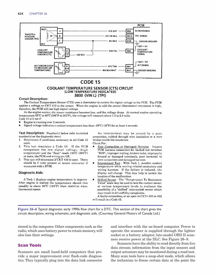
Figure 26–6 Typical diagnostic early 1990s flow chart for a DTC. This section of the chart gives thecircuit description, wiring schematic, and diagnostic aids. (Courtesy General Motors of Canada Ltd.)
driveability concern arrives.This information can thenbe reviewed and interpreted back in the service bay.The majority of Asian and European vehicles haveno provisions for live data stream readouts withearly on-board diagnostics. Today, virtually every au-tomobile sold in Canada and the U.S. is equipped toprovide running data.
Scanners also supply trouble code information innumerical form; there are no light flashes or needlesweeps to count.
Some scanners have the ability to control the out-put actuators and solenoids for test purposes. Per-forming a cylinder-balance test by interrupting the ig-nition spark is a common diagnostic routine used with
Computers and On-Board Diagnostics 625
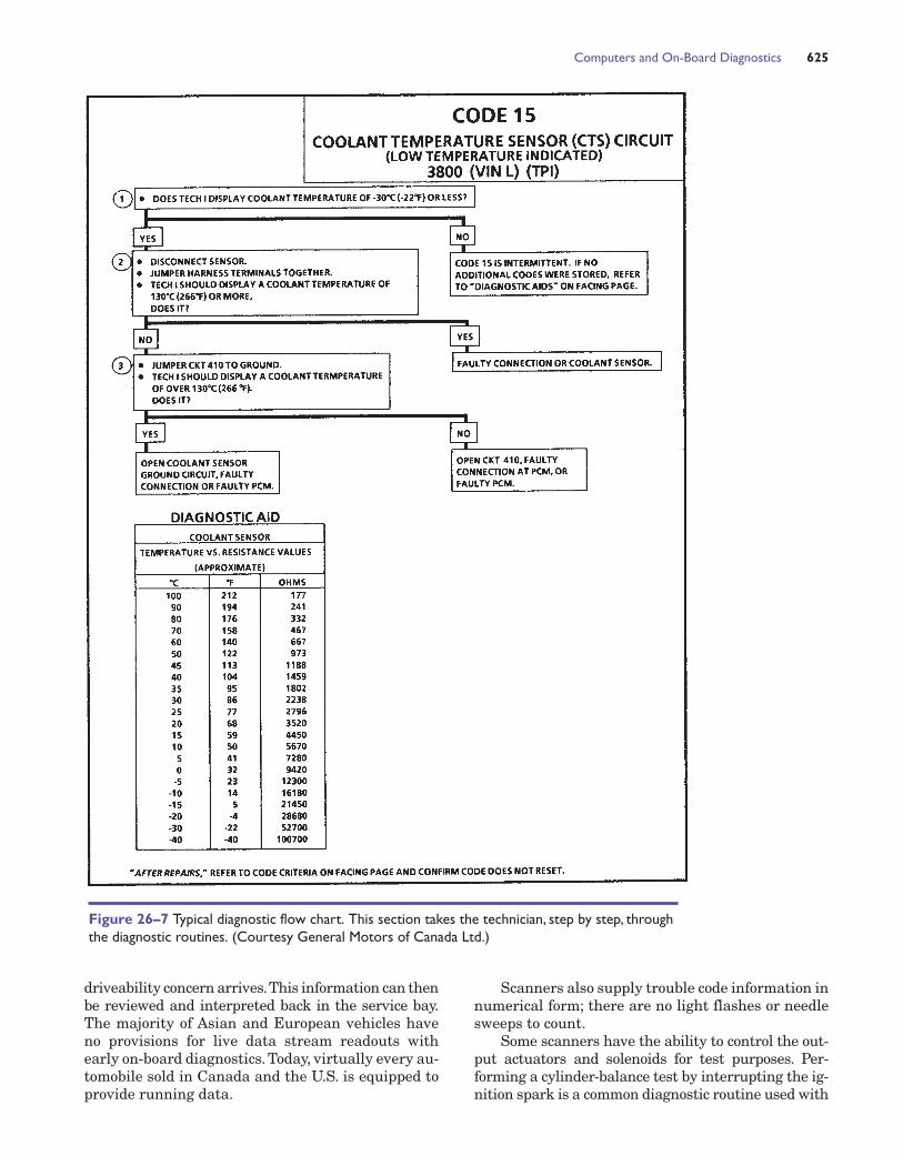
Figure 26–7 Typical diagnostic flow chart. This section takes the technician, step by step, throughthe diagnostic routines. (Courtesy General Motors of Canada Ltd.)
many large oscilloscopes.This must be done very care-fully, as the fuel and air from the dead cylinder willflow into the catalytic converter, causing it to overheat.Feeding the converter raw fuel and oxygen causes in-ternal catalyst temperatures to rise quickly and theconverter will begin to melt if the cylinder is "killed"for long. Vehicles with sequential (individual injectorcontrol) fuel injection often use scanners to cancel eachfuel injector, instead of ignition, for cylinder balancetesting.This protects the converter and eliminates anychance of a backfire in the exhaust pipes.
Many late vehicles have no provision for flash-code retrieval and a scanner must be used to extracttrouble codes.
On-Board Diagnostics:Generation I (OBD I)
The California Air Resources Board (CARB) devel-oped the first regulation requiring manufacturersselling vehicles in that state to install OBD. CalledOBD Generation I (OBD I), OBD I applies to all ve-hicles sold in California beginning with the 1988model year. It carries the following requirements:
1. An instrument panel warning lamp able toalert the driver of certain control systemfailures, now called a malfunction indicatorlamp (MIL).
2. The system's ability to record and transmitdiagnostic trouble codes (DTCs) foremission-related failures.
3. Electronic system monitoring of the HO2S, EGRvalve, and evaporative purge solenoid. Althoughnot EPA-required during this time, mostmanufacturers also equipped vehicles soldoutside of California with OBD I.
These initial regulations failed to meet many expecta-tions. By failing to monitor the catalytic converter, theevaporative system for leaks, and the presence of en-gine misfire, OBD I did not do enough to lower auto-motive emissions. In addition, the OBD I monitoringcircuits that were installed lacked sufficient sensitivity.
Aside from OBD I's lack of emission-reductioneffectiveness, another problem existed. Auto manu-facturers implemented OBD I rules as they saw fit,resulting in a vast array of servicing tools and sys-tems. Rather than simplifying the job of locatingand repairing a failure, the aftermarket technicianfaced a tangled network of procedures often requir-ing the use of expensive special test equipment anddealer-proprietary information.
Soon it became apparent that more stringentmeasures were needed if the ultimate goal, reducedautomotive emission levels, was to be achieved. Thisled to the development of OBD Generation II (OBD II).
OBD II Objectives
Generally an OBD II vehicle is defined by its ability to:
1. Detect component degradation or a faultyemission-related system that preventscompliance with federal emission standards.
2. Alert the driver of needed emission-relatedrepair or maintenance.
3. Use standardized DTCs and accept a genericscan tool.
OBD II was first introduced on some 1994 vehicles;by 1998, all light-duty vehicles sold in Canada (U.S.1996) were required to be OBD II compliant. The pri-mary purpose of OBD II is emission-related,whereas the primary purpose of OBD I (1988) wasto detect faults in sensors or sensor circuits. OBD IIregulations require that not only must the sensorsbe tested but that all exhaust control devices betested and verified for proper operation.
All new vehicles must pass the Federal TestProcedure (FTP) for exhaust emissions while be-ing tested for 505 seconds on rollers that simulatethe urban drive cycle around downtown Los Angeles,California.
The regulations for OBD II vehicles state that thevehicle computer must be capable of testing for ex-haust emissions, and determining whether or not theyare within 1 1/2 times the allowable standard for a newvehicle based on the FTP limits. In order to achievethis goal, the computer has to do all of the following:
NOTE: IM 240 is simply a shorter version of the 505-second-long federal test procedure.
626 CHAPTER 26
Figure 26–8 Hand-held scan tools interface with the on-board computer. They not only extract fault codes (DTC),they read live data from the sensors and actuators. Priorto OBD II, the scan tool required a different DLC adaptorand program cartridge when switching between makes.(Courtesy Toyota Canada Inc.)
1. Test all exhaust emission system componentsfor correct operation.
2. Actively operate the system and measure theresults.
3. Continuously monitor all aspects of the engineoperation to be certain that the exhaustemissions do not exceed 1 1/2 times the FTP.
4. Check engine operation for misfire.5. Turn on the malfunction indicator lamp (MIL)
(check engine) if the computer senses a fault in acircuit or system.
6. Flash the MIL if an engine misfire occurs thatcould damage the catalytic converter.
Comprehensive ComponentMonitor
The comprehensive component monitor (CCM)is an internal program in the PCM designed to mon-itor a failure in any electronic component or circuit(including emission-related and non-emission-relatedcircuits) that provide input or output signals to thePCM. The PCM considers that an input or output sig-nal is inoperative when a failure exists due to an opencircuit, out-of-range value or if an on-board rational-ity check fails. If an emission-related fault is de-tected, the PCM will set a code and activate the MIL(requires two consecutive trips). Some exceptions are(a) serious engine misfire that could damage the cat-alytic converter—this requires one trip only; (b) cata-lyst monitoring which requires three trips.
Many PCM sensors and output devices are testedat key on or immediately after engine startup. How-ever, some devices, such as the idle air control (IAC),are only tested by the CCM after the engine meetscertain engine conditions. The number of times theCCM must detect a fault before it will activate theMIL depends upon the manufacturer, but most re-quire two consecutive trips to activate the MIL. Thecomponents tested by the CCM include:
■ 4-wheel-drive low switch■ Brake switch■ Camshaft (CMP) and crankshaft (CKP) sensors■ Clutch switch (manual transmissions/transaxles
only)■ Cruise servo switch■ Engine coolant temperature (ECT) sensor■ EVAP purge sensor or switch■ Fuel composition sensor■ Intake air temperature (IAT) sensor■ Knock sensor (KS)■ Manifold absolute pressure (MAP) sensor■ Mass airflow (MAF) sensor■ Transmission fluid temperature (TFT) sensor■ Transmission turbine speed sensor■ Vacuum sensor■ Vehicle speed (VS) sensor
■ EVAP canister purge and EVAP purge ventsolenoid
■ Idle air control solenoid■ Ignition control system■ Transmission torque converter clutch solenoid■ Transmission shift solenoids
Main Monitors
On OBD II systems, the PCM incorporates a specialsegment of software. This software program is de-signed to manage the operation of all OBD II moni-tors by controlling the sequence of steps necessary toexecute the diagnostic tests and monitors:
■ Comprehensive component monitor■ Catalyst monitor■ EGR and EVAP system monitors■ Fuel system monitor■ Misfire monitor■ Oxygen sensor monitor■ Oxygen sensor heater monitor■ Secondary AIR system monitor
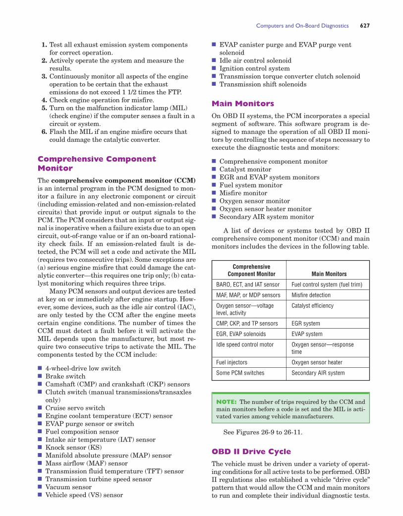
A list of devices or systems tested by OBD IIcomprehensive component monitor (CCM) and mainmonitors includes the devices in the following table.
Computers and On-Board Diagnostics 627
Comprehensive Component Monitor Main Monitors
BARO, ECT, and IAT sensor Fuel control system (fuel trim)
MAF, MAP, or MDP sensors Misfire detection
Oxygen sensor—voltage Catalyst efficiencylevel, activity
CMP, CKP, and TP sensors EGR system
EGR, EVAP solenoids EVAP system
Idle speed control motor Oxygen sensor—responsetime
Fuel injectors Oxygen sensor heater
Some PCM switches Secondary AIR system
See Figures 26-9 to 26-11.
OBD II Drive Cycle
The vehicle must be driven under a variety of operat-ing conditions for all active tests to be performed. OBDII regulations also established a vehicle “drive cycle”pattern that would allow the CCM and main monitorsto run and complete their individual diagnostic tests.
NOTE: The number of trips required by the CCM andmain monitors before a code is set and the MIL is acti-vated varies among vehicle manufacturers.
628
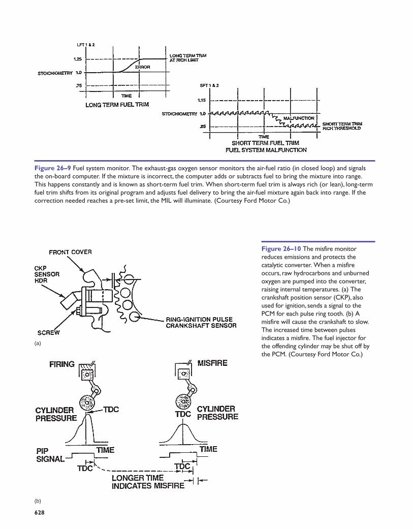
Figure 26–9 Fuel system monitor. The exhaust-gas oxygen sensor monitors the air-fuel ratio (in closed loop) and signalsthe on-board computer. If the mixture is incorrect, the computer adds or subtracts fuel to bring the mixture into range.This happens constantly and is known as short-term fuel trim. When short-term fuel trim is always rich (or lean), long-termfuel trim shifts from its original program and adjusts fuel delivery to bring the air-fuel mixture again back into range. If thecorrection needed reaches a pre-set limit, the MIL will illuminate. (Courtesy Ford Motor Co.)
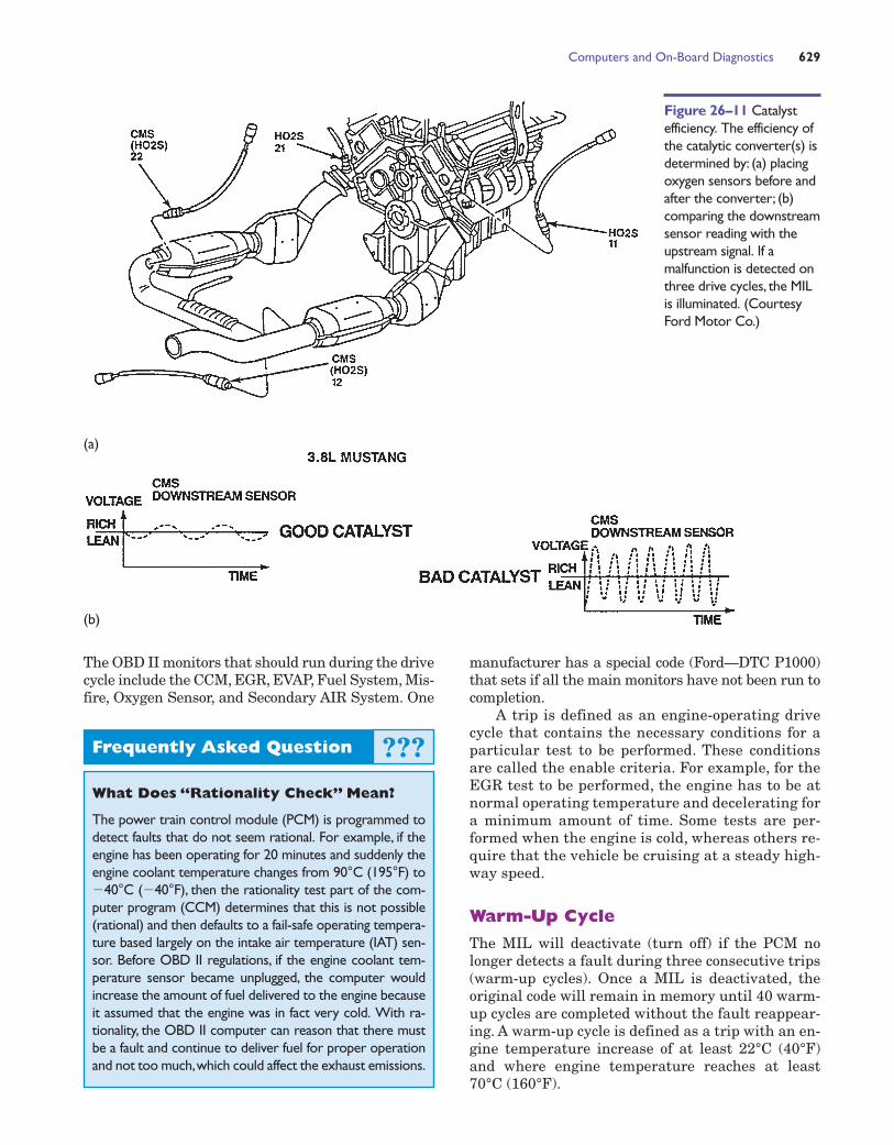
Figure 26–10 The misfire monitorreduces emissions and protects thecatalytic converter. When a misfireoccurs, raw hydrocarbons and unburnedoxygen are pumped into the converter,raising internal temperatures. (a) Thecrankshaft position sensor (CKP), alsoused for ignition, sends a signal to thePCM for each pulse ring tooth. (b) Amisfire will cause the crankshaft to slow.The increased time between pulsesindicates a misfire. The fuel injector forthe offending cylinder may be shut off bythe PCM. (Courtesy Ford Motor Co.)
(a)
(b)
Computers and On-Board Diagnostics 629
manufacturer has a special code (Ford—DTC P1000)that sets if all the main monitors have not been run tocompletion.
A trip is defined as an engine-operating drivecycle that contains the necessary conditions for aparticular test to be performed. These conditionsare called the enable criteria. For example, for theEGR test to be performed, the engine has to be atnormal operating temperature and decelerating fora minimum amount of time. Some tests are per-formed when the engine is cold, whereas others re-quire that the vehicle be cruising at a steady high-way speed.
Warm-Up Cycle
The MIL will deactivate (turn off) if the PCM nolonger detects a fault during three consecutive trips(warm-up cycles). Once a MIL is deactivated, theoriginal code will remain in memory until 40 warm-up cycles are completed without the fault reappear-ing. A warm-up cycle is defined as a trip with an en-gine temperature increase of at least 22°C (40°F)and where engine temperature reaches at least70°C (160°F).
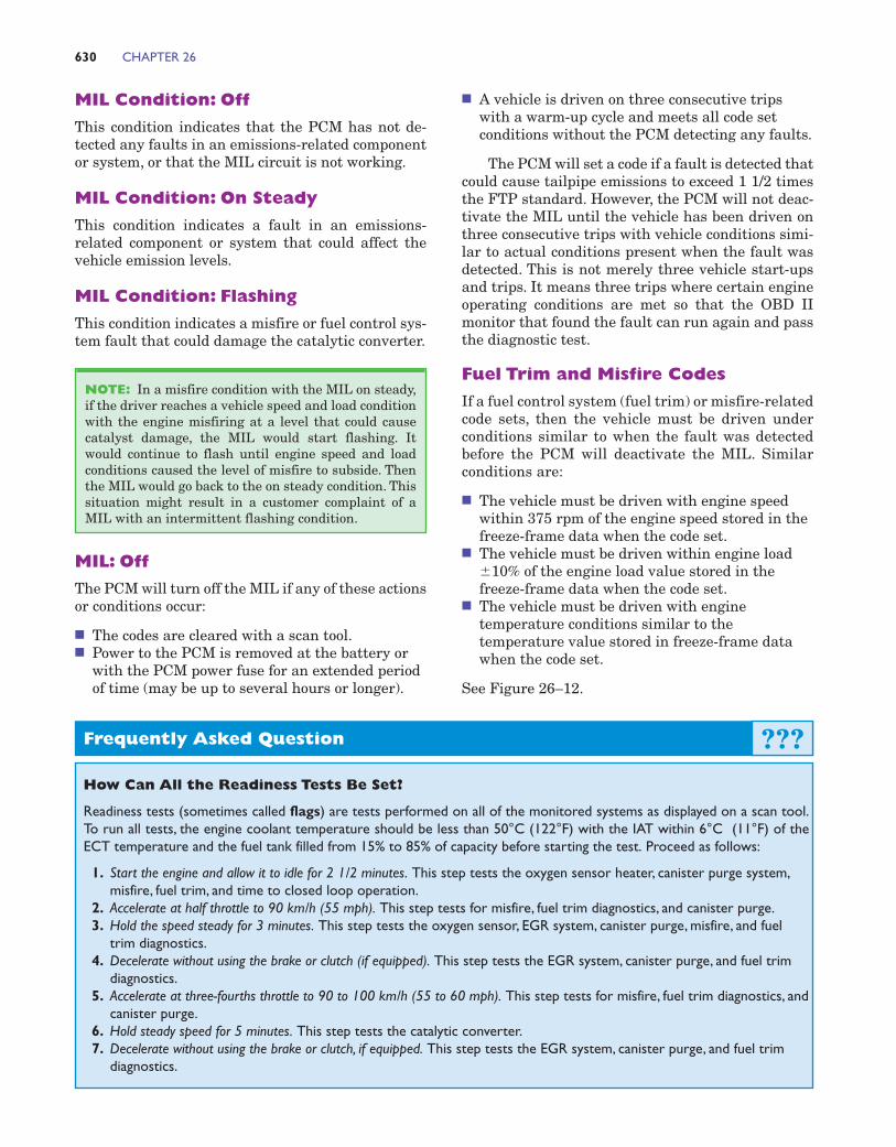
Figure 26–11 Catalystefficiency. The efficiency ofthe catalytic converter(s) isdetermined by: (a) placingoxygen sensors before andafter the converter; (b)comparing the downstreamsensor reading with theupstream signal. If amalfunction is detected onthree drive cycles, the MILis illuminated. (CourtesyFord Motor Co.)
(a)
(b)
Frequently Asked Question
What Does “Rationality Check” Mean?
The power train control module (PCM) is programmed todetect faults that do not seem rational. For example, if theengine has been operating for 20 minutes and suddenly theengine coolant temperature changes from 90°C (195°F) to�40°C (�40°F), then the rationality test part of the com-puter program (CCM) determines that this is not possible(rational) and then defaults to a fail-safe operating tempera-ture based largely on the intake air temperature (IAT) sen-sor. Before OBD II regulations, if the engine coolant tem-perature sensor became unplugged, the computer wouldincrease the amount of fuel delivered to the engine becauseit assumed that the engine was in fact very cold. With ra-tionality, the OBD II computer can reason that there mustbe a fault and continue to deliver fuel for proper operationand not too much,which could affect the exhaust emissions.
???
The OBD II monitors that should run during the drivecycle include the CCM, EGR, EVAP, Fuel System, Mis-fire, Oxygen Sensor, and Secondary AIR System. One
■ A vehicle is driven on three consecutive tripswith a warm-up cycle and meets all code setconditions without the PCM detecting any faults.
The PCM will set a code if a fault is detected thatcould cause tailpipe emissions to exceed 1 1/2 timesthe FTP standard. However, the PCM will not deac-tivate the MIL until the vehicle has been driven onthree consecutive trips with vehicle conditions simi-lar to actual conditions present when the fault wasdetected. This is not merely three vehicle start-upsand trips. It means three trips where certain engineoperating conditions are met so that the OBD IImonitor that found the fault can run again and passthe diagnostic test.
Fuel Trim and Misfire Codes
If a fuel control system (fuel trim) or misfire-relatedcode sets, then the vehicle must be driven underconditions similar to when the fault was detectedbefore the PCM will deactivate the MIL. Similarconditions are:
■ The vehicle must be driven with engine speedwithin 375 rpm of the engine speed stored in thefreeze-frame data when the code set.
■ The vehicle must be driven within engine load�10% of the engine load value stored in thefreeze-frame data when the code set.
■ The vehicle must be driven with enginetemperature conditions similar to thetemperature value stored in freeze-frame datawhen the code set.
See Figure 26–12.
630 CHAPTER 26
MIL Condition: Off
This condition indicates that the PCM has not de-tected any faults in an emissions-related componentor system, or that the MIL circuit is not working.
MIL Condition: On Steady
This condition indicates a fault in an emissions-related component or system that could affect thevehicle emission levels.
MIL Condition: Flashing
This condition indicates a misfire or fuel control sys-tem fault that could damage the catalytic converter.
MIL: Off
The PCM will turn off the MIL if any of these actionsor conditions occur:
■ The codes are cleared with a scan tool.■ Power to the PCM is removed at the battery or
with the PCM power fuse for an extended periodof time (may be up to several hours or longer).
NOTE: In a misfire condition with the MIL on steady,if the driver reaches a vehicle speed and load conditionwith the engine misfiring at a level that could causecatalyst damage, the MIL would start flashing. Itwould continue to flash until engine speed and loadconditions caused the level of misfire to subside. Thenthe MIL would go back to the on steady condition. Thissituation might result in a customer complaint of aMIL with an intermittent flashing condition.
Frequently Asked Question
How Can All the Readiness Tests Be Set?
Readiness tests (sometimes called flags) are tests performed on all of the monitored systems as displayed on a scan tool.To run all tests, the engine coolant temperature should be less than 50°C (122°F) with the IAT within 6°C (11°F) of theECT temperature and the fuel tank filled from 15% to 85% of capacity before starting the test. Proceed as follows:
1. Start the engine and allow it to idle for 2 1/2 minutes. This step tests the oxygen sensor heater, canister purge system,misfire, fuel trim, and time to closed loop operation.
2. Accelerate at half throttle to 90 km/h (55 mph). This step tests for misfire, fuel trim diagnostics, and canister purge.3. Hold the speed steady for 3 minutes. This step tests the oxygen sensor, EGR system, canister purge, misfire, and fuel
trim diagnostics.4. Decelerate without using the brake or clutch (if equipped). This step tests the EGR system, canister purge, and fuel trim
diagnostics.5. Accelerate at three-fourths throttle to 90 to 100 km/h (55 to 60 mph). This step tests for misfire, fuel trim diagnostics, and
canister purge.6. Hold steady speed for 5 minutes. This step tests the catalytic converter.7. Decelerate without using the brake or clutch, if equipped. This step tests the EGR system, canister purge, and fuel trim
diagnostics.
???
Computers and On-Board Diagnostics 631
Figure 26–12 How a PCM turns on the MIL.
First failure
TRIP (Run Monitors)
Type A—First failureof Type A (one-trip)fault on this key cycle
Type B—First failure ofType B (two-trip) fault onthis key cycle that is not aFuel Problem or Misfire
Type B—Secondconsecutive failure of TypeB (two-trip) fault that isnot Fuel Problem orMisfire
Request MIL on and writeFreeze Frame—StoresDTC
Type B—Second non-consecutive Fuel Problemor Misfire failure undersimilar conditions in next80 trips
Type B—First failure ofType B (two-trip) for FuelProblem or Misfire willarm DTC and run Monitorfor next 80 non-consecutive trips
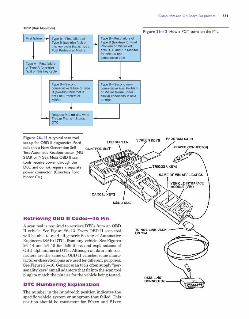
Figure 26–13 A typical scan toolset up for OBD II diagnostics. Fordcalls this a New Generation Self-Test Automatic Readout tester (NGSTAR or NGS). Most OBD II scantools receive power through theDLC and do not require a separatepower connector. (Courtesy FordMotor Co.)
Retrieving OBD II Codes—16 Pin
A scan tool is required to retrieve DTCs from an OBDII vehicle. See Figure 26–13. Every OBD II scan toolwill be able to read all generic Society of AutomotiveEngineers (SAE) DTCs from any vehicle. See Figures26–14 and 26–15 for definitions and explanations ofOBD alphanumeric DTCs. Although all data link con-nectors are the same on OBD II vehicles, some manu-facturer-discretion pins are used for different purposes.See Figure 26–16. Generic scan tools often supply "per-sonality keys" (small adaptors that fit into the scan toolplug) to match the pin use for the vehicle being tested.
DTC Numbering Explanation
The number in the hundredth position indicates thespecific vehicle system or subgroup that failed. Thisposition should be consistent for P0xxx and P1xxx
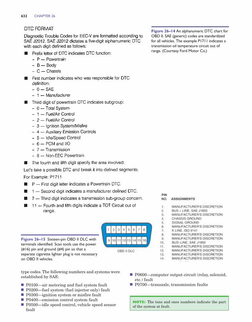
type codes. The following numbers and systems wereestablished by SAE:
■ P0100—air metering and fuel system fault■ P0200—fuel system (fuel injector only) fault■ P0300—ignition system or misfire fault■ P0400—emission control system fault■ P0500—idle speed control, vehicle speed sensor
fault
632 CHAPTER 26
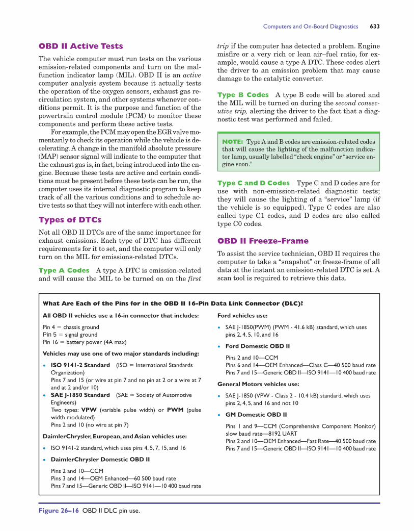
Figure 26–15 Sixteen-pin OBD II DLC withterminals identified. Scan tools use the power(#16) pin and ground (#4) pin so that aseparate cigarette lighter plug is not necessaryon OBD II vehicles.
Figure 26–14 An alphanumeric DTC chart forOBD II. SAE (generic) codes are standardizedfor all vehicles. The example P1711 indicates atransmission oil temperature circuit out ofrange. (Courtesy Ford Motor Co.)
■ P0600—computer output circuit (relay, solenoid,etc.) fault
■ P0700—transaxle, transmission faults
NOTE: The tens and ones numbers indicate the partof the system at fault.
Computers and On-Board Diagnostics 633
OBD II Active Tests
The vehicle computer must run tests on the variousemission-related components and turn on the mal-function indicator lamp (MIL). OBD II is an activecomputer analysis system because it actually teststhe operation of the oxygen sensors, exhaust gas re-circulation system, and other systems whenever con-ditions permit. It is the purpose and function of thepowertrain control module (PCM) to monitor thesecomponents and perform these active tests.
For example,the PCM may open the EGR valve mo-mentarily to check its operation while the vehicle is de-celerating. A change in the manifold absolute pressure(MAP) sensor signal will indicate to the computer thatthe exhaust gas is, in fact, being introduced into the en-gine. Because these tests are active and certain condi-tions must be present before these tests can be run, thecomputer uses its internal diagnostic program to keeptrack of all the various conditions and to schedule ac-tive tests so that they will not interfere with each other.
Types of DTCs
Not all OBD II DTCs are of the same importance forexhaust emissions. Each type of DTC has differentrequirements for it to set, and the computer will onlyturn on the MIL for emissions-related DTCs.
Type A Codes A type A DTC is emission-relatedand will cause the MIL to be turned on on the first
What Are Each of the Pins for in the OBD II 16-Pin Data Link Connector (DLC)?
Ford vehicles use:
• SAE J-1850(PWM) (PWM - 41.6 kB) standard, which usespins 2, 4, 5, 10, and 16
• Ford Domestic OBD II
Pins 2 and 10—CCMPins 6 and 14—OEM Enhanced—Class C—40 500 baud ratePins 7 and 15—Generic OBD II—ISO 9141—10 400 baud rate
General Motors vehicles use:
• SAE J-1850 (VPW - Class 2 - 10.4 kB) standard, which usespins 2, 4, 5, and 16 and not 10
• GM Domestic OBD II
Pins 1 and 9—CCM (Comprehensive Component Monitor)slow baud rate—8192 UARTPins 2 and 10—OEM Enhanced—Fast Rate—40 500 baud ratePins 7 and 15—Generic OBD II—ISO 9141—10 400 baud rate
All OBD II vehicles use a 16-in connector that includes:
Pin 4 � chassis groundPin 5 � signal groundPin 16 � battery power (4A max)
Vehicles may use one of two major standards including:
• ISO 9141-2 Standard (ISO � International StandardsOrganization)Pins 7 and 15 (or wire at pin 7 and no pin at 2 or a wire at 7and at 2 and/or 10)
• SAE J-1850 Standard (SAE � Society of AutomotiveEngineers)Two types: VPW (variable pulse width) or PWM (pulsewidth modulated)Pins 2 and 10 (no wire at pin 7)
DaimlerChrysler, European, and Asian vehicles use:
• ISO 9141-2 standard, which uses pins 4, 5, 7, 15, and 16
• DaimlerChrysler Domestic OBD II
Pins 2 and 10—CCMPins 3 and 14—OEM Enhanced—60 500 baud ratePins 7 and 15—Generic OBD II—ISO 9141—10 400 baud rate
Figure 26–16 OBD II DLC pin use.
trip if the computer has detected a problem. Enginemisfire or a very rich or lean air–fuel ratio, for ex-ample, would cause a type A DTC. These codes alertthe driver to an emission problem that may causedamage to the catalytic converter.
Type B Codes A type B code will be stored andthe MIL will be turned on during the second consec-utive trip, alerting the driver to the fact that a diag-nostic test was performed and failed.
Type C and D Codes Type C and D codes are foruse with non-emission-related diagnostic tests;they will cause the lighting of a “service” lamp (ifthe vehicle is so equipped). Type C codes are alsocalled type C1 codes, and D codes are also calledtype C0 codes.
OBD II Freeze-Frame
To assist the service technician, OBD II requires thecomputer to take a “snapshot” or freeze-frame of alldata at the instant an emission-related DTC is set. Ascan tool is required to retrieve this data.
NOTE: Type A and B codes are emission-related codesthat will cause the lighting of the malfunction indica-tor lamp, usually labelled “check engine” or “service en-gine soon.”
Freeze-frame items include:
■ Calculated load value■ Engine speed (RPM)■ Short-term and long-term fuel trim percent■ Fuel system pressure (on some vehicles)■ Vehicle speed (km/h or mph)■ Engine coolant temperature (ECT)■ Intake manifold pressure■ Closed/open loop status■ Fault code that triggered the freeze-frame■ If a misfire code is set, identify which cylinder is
misfiring
Clearing OBD II DTCs
A DTC should not be cleared from the vehicle com-puter memory unless the fault has been corrected andthe technician is so directed by the diagnostic proce-dure. If the problem that caused the DTC to be set hasbeen corrected, the computer will automatically clearthe DTC after 40 consecutive warm-up cycles with nofurther faults detected (misfire and excessively rich orlean condition codes require 80 warm-up cycles). Thecodes can also be erased by using a scan tool.
Diagnostic Procedures
Diagnostic procedures for OBD I and OBD II vehi-cles are covered in Chapter 31, “Engine PerformanceDiagnosis and Testing.”
DIAGNOSING COMPUTERPROBLEMS
If a computer fails, it is often difficult to determine ifthe computer itself is at fault or if there is a problemwith some other system in the vehicle. For example,if the engine stalls, it could be the result of a fault inthe ignition system, fuel system, or a failed sensorsuch as a crankshaft position sensor (CKP).
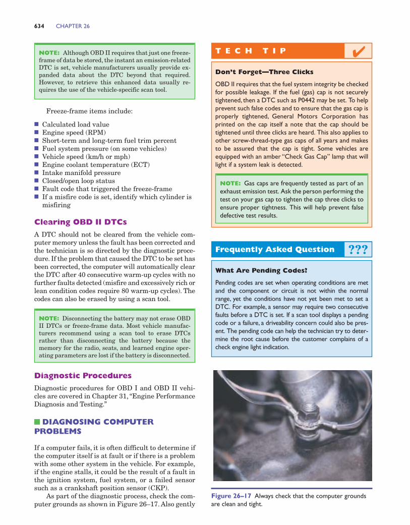
As part of the diagnostic process, check the com-puter grounds as shown in Figure 26–17. Also gently
NOTE: Disconnecting the battery may not erase OBDII DTCs or freeze-frame data. Most vehicle manufac-turers recommend using a scan tool to erase DTCsrather than disconnecting the battery because thememory for the radio, seats, and learned engine oper-ating parameters are lost if the battery is disconnected.
NOTE: Although OBD II requires that just one freeze-frame of data be stored, the instant an emission-relatedDTC is set, vehicle manufacturers usually provide ex-panded data about the DTC beyond that required.However, to retrieve this enhanced data usually re-quires the use of the vehicle-specific scan tool.
634 CHAPTER 26
Figure 26–17 Always check that the computer groundsare clean and tight.
T E C H T I P
Don’t Forget—Three Clicks
OBD II requires that the fuel system integrity be checkedfor possible leakage. If the fuel (gas) cap is not securelytightened, then a DTC such as P0442 may be set. To helpprevent such false codes and to ensure that the gas cap isproperly tightened, General Motors Corporation hasprinted on the cap itself a note that the cap should betightened until three clicks are heard. This also applies toother screw-thread-type gas caps of all years and makesto be assured that the cap is tight. Some vehicles areequipped with an amber “Check Gas Cap” lamp that willlight if a system leak is detected.
NOTE: Gas caps are frequently tested as part of anexhaust emission test. Ask the person performing thetest on your gas cap to tighten the cap three clicks toensure proper tightness. This will help prevent falsedefective test results.
✔
Frequently Asked Question
What Are Pending Codes?
Pending codes are set when operating conditions are metand the component or circuit is not within the normalrange, yet the conditions have not yet been met to set aDTC. For example, a sensor may require two consecutivefaults before a DTC is set. If a scan tool displays a pendingcode or a failure, a driveability concern could also be pres-ent. The pending code can help the technician try to deter-mine the root cause before the customer complains of acheck engine light indication.
???
Computers and On-Board Diagnostics 635
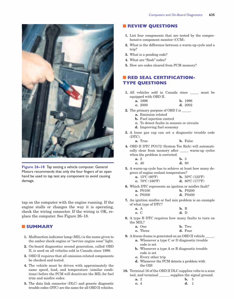
tap on the computer with the engine running. If theengine stalls or changes the way it is operating,check the wiring connecter. If the wiring is OK, re-place the computer. See Figure 26–18.
SUMMARY
1. Malfunction indicator lamp (MIL) is the name given tothe amber check engine or “service engine soon” light.
2. On-board diagnostics second generation, called OBDII, is used on all vehicles sold in Canada since 1998.
3. OBD II requires that all emission-related componentsbe checked and tested.
4. The vehicle must be driven with approximately thesame speed, load, and temperature (similar condi-tions) before the PCM will deactivate the MIL for fueltrim and misfire codes.
5. The data link connector (DLC) and generic diagnostictrouble codes (DTC) are the same for all OBD II vehicles.
Figure 26–18 Tap testing a vehicle computer. GeneralMotors recommends that only the four fingers of an openhand be used to tap test any component to avoid causingdamage.
REVIEW QUESTIONS
1. List four components that are tested by the compre-hensive component monitor (CCM).
2. What is the difference between a warm-up cycle and atrip?
3. What is a pending code?
4. What are “flash” codes?
5. How are codes cleared from PCM memory?
RED SEAL CERTIFICATION-TYPE QUESTIONS
1. All vehicles sold in Canada since _____ must beequipped with OBD II.
a. 1996 b. 1998c. 2000 d. 2002
2. The primary purpose of OBD I is _____.a. Emission relatedb. Fuel injection controlc. To detect faults in sensors or circuitsd. Improving fuel economy
3. A loose gas cap can set a diagnostic trouble code(DTC).
a. True b. False
4. OBD II DTC PO172 (System Too Rich) will automati-cally clear from memory after _____ warm-up cycleswhen the problem is corrected.
a. 2 b. 3c. 40 d. 80
5. A warm-up cycle has to achieve at least how many de-grees of engine coolant temperature?
a. 15ºC (60ºF) b. 50ºC (122ºF)c. 70ºC (160ºF) d. 80ºC (177ºF)
6. Which DTC represents an ignition or misfire fault?a. P0100 b. P0200c. P0300 d. P0400
7. An ignition misfire or fuel mix problem is an exampleof what type of DTC?
a. A b. Bc. C d. D
8. A type B DTC requires how many faults to turn onthe MIL?
a. One b. Twoc. Three d. Four
9. A freeze-frame is generated on an OBD II vehicle _____.a. Whenever a type C or D diagnostic trouble
code is setb. Whenever a type A or B diagnostic trouble
code is setc. Every other tripd. Whenever the PCM detects a problem with
the O2S
10. Terminal 16 of the OBD II DLC supplies volts to a scantool, and terminal ______ supplies the signal ground.
a. 2 b. 5c. 4 d. 1