Embed Size (px)
Citation preview
Development of low cost, on-board ATS-P
technology at the East Japan Railway Company
Masakazu Miyachi* & Yuichi Sakuma*
"Safety Research Laboratory
T̂okyo Electric Construction Department, East Japan Railway
Company, Japan
Abstract
The East Japan Railway Company (JR East) has been in pursuit of aninexpensive ATS-P system since 1994. The first result of this development isthe ATS-P(N) ground system. The installation cost of the ATS-P^ groundsystem is half of that for the ATS-P ground system.The second result of this development is the reducing in costs and downsizing
of the ATS-P on-board system. The current ATS-P on-board system iscomposed of several devices. But the new (integrated) ATS-P on-board systemis composed of one main devices, a smaller relay block and so on. This secondadvance results in a system with about 70% of the cost, 50% of the weight, and70% of the size of the current newest on-board system. The integrated on-boardsystem will be installed in newly-built trains in 1999.
Background
At JR East, the ATS-P (Automatic Train Stop with on-board Pattern)system is used to improve the safety of train operation on a total of 800km lines in the Tokyo metropolitan area. This system is preferred overthe ATS-SN (Automatic Train Stop- Standard and New) system for thismajor hub due to its higher assurance safety.Both ATS systems operate by sending information at intervals from the
ground to the train. But only the ATS-P system has on-board equipmentto continuously monitor the train speed.Although the ATS-P system offers greater safety guarantees than theATS-SN system, the installation cost of the ATS-P system iscorrespondingly higher.
Transactions on the Built Environment vol 34, © 1998 WIT Press, www.witpress.com, ISSN 1743-3509
1038 Computers in Railways
Therefore inexpensive ATS-P options have been sought and developed
since 1994, including an ATS-P(̂ ) ground system and an integrated on-board system.
1 The ATS-P System^
Transponders serve as digital communication devices for sending andreceiving information between ground coils and on-board coils.Some transmission specifications for the transponder are given in Table
1.
Table 1 Transmission specifications for transponderTransmission
InformationTransmission
Energy transmission
Ground— > trainTrain
— > ground
Train -> ground
Frequency etc.1.7MHz (FSK modulation)
64kbit/s3.0MHz (FSK modulation)
64kbit/s245kHz
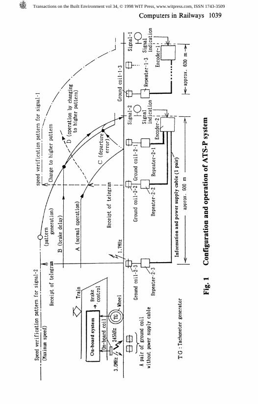
The fixed train information is transmitted by electromagnetic wavesfrom an on-board coil. ATS-P uses a transponder to enable the ground-to-train transmission of a large quantity of information.As shown in Fig.l, the ATS-P system is divided into a ground system
and an on-board system. The ground system in each block consists ofone encoder and several repeaters for each ground coil. The encodertransmits the telegraphic messages concerning the current status of thesignal to each repeater. The repeater then sends, at 64kbit/s, thesetelegraphic messages to a train through a ground coil by means of a FSKmodulated signal. Conversely, the repeater sends at 1200bit/s thetelegraphic messages received from a train through the ground coil, tothe encoder. Each encoder is connected to the corresponding repeaters bya pair of cables to transmit information and power.The pair of ground coils, powered by energy transmitted from an on-
board coil, sends to the on-board coil fixed information such as the speedlimit of a curve.The on-board system then decodes this telegraphic information and
automatically activates the brake when the actual speed read by atachometer-generator (TG) exceeds the on-board speed verificationpattern.The ground system and the on-board system are both microelectronic
products, incorporating 'fail-safe' microcomputers.The primary objective of the ATS-P system is the prevention of
accidents due to either a stop signal violation or speeding at places such
Transactions on the Built Environment vol 34, © 1998 WIT Press, www.witpress.com, ISSN 1743-3509
Computers in Railways 1039
C/5
C.2̂wCQO>GLO
aCQO,0%*2
IaoU
Ofi
Transactions on the Built Environment vol 34, © 1998 WIT Press, www.witpress.com, ISSN 1743-3509
1040 Computers in Railways
as turnouts or curves. Fig. 1 shows the system setup. When signal-2 isindicating 'stop', ground coil-2-3 sends to the train the 'distance tosignal-2' information. The controller then generates a speed patternwhen the train is about 600 meters ahead of the signal.Once the pattern is generated, the train speed is continuously compared
with the pattern speed and the brake is automatically activated if the train
speed is higher. This speed check assures that the train stops before thestop signal-2.In Fig.l, case A shows the history of the train speed during normal
operation, B is the case of late brake application (resulting in automaticbraking), and C illustrates the situation of a train departing when itshould not depart. When signal-2 switches from a 'stop' to a 'clear'signal after the stop pattern has just been generated, the on-board patternmust be updated so as to not halt the train unnecessarily. Dotted line Drepresents this case. Once the train reaches ground coil-2-2, the stopinformation will be updated; Ground coil-2-2 will send to the on-boarddevice the new stopping distance to the next stop signal, signal-1. Atthis point, if the emergency brake had been activated, the shift in theprotection pattern would release the emergency brake.
2 The ATS-P(N) Ground System
In 1995, in order to install ATS-P on lines with moderate traffic, a cost-effective ground infrastructure called ATS-P^ (standing for 'new ATS-P') was developed. The basic requirements of ATS-P^ include safetyequal to the ATS-P standard, low cost, and use of current ATS-P on-board devices without remodeling.ATS-P(N) also uses the transponder technology and in addition, makes
full use of the ground coils without a power supply cable. The ATS-P(N> ground infrastructure uses several ground coils and relay-modulesfor consecutive transmission of train control information to keep the on-board system current on the status of the signals.The ATS-P(N) system has a simpler ground infrastructure than that of
the ATS-P, and the need for cable construction is nominal becauseexisting cable for ATS-SN can be used. Therefore the total cost ofATS-P(N) is only about 50% of that of the ATS-P ground infrastructure.This new system will be installed on the Kawagoe line (15km) and theMusashino line (72km) in the Tokyo metropolitan area and will be in useby March 1999.A comparison between the ATS-P and ATS-P^ ground systems is
given in Table 2.
Transactions on the Built Environment vol 34, © 1998 WIT Press, www.witpress.com, ISSN 1743-3509
Computers in Railways 1041
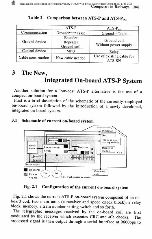
Table 2 Comparison between ATS-P and ATS-P^
Communication
Ground device
Control device
Cable construction
ATS-P
Ground* — TrainEncoderRepeater
Ground coilMPU
New cable needed
ATS-P™
Ground— >Train
Ground coilWithout power supply
RelayUse of existing cable for
ATS-SN
3 The New,
Integrated On-board ATS-P System
Another solution for a low-cost ATS-P alternative is the use of acompact on-board system.
First is a brief description of the schematic of the currently employedon-board system followed by the introduction of a newly developed,integrated on-board system.
3.1 Schematic of current on-board system
II
1Bra
M ;
s
lelay>lock -
JCH. ICHce ord
SbilCP'owerupply
m* .-
R-1 {R-2 |er
"Ci
fr-̂ mK
Speed check ^^)lock ^̂ H
k j
bdi)_-^TG : Ta
L*— Z
JCFRICFR
chome
^
•Receiver
MMT̂.lj ICH
-2f t | ICH
ter genera
x̂
R-1R-2
or
^
^'BellTrain numsetting sw
Directionswitch
On-boardcoil
s
hertch
- Cab
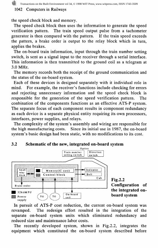
Fig. 2.1 Configuration of the current on-board system
Fig. 2.1 shows the current ATS-P on-board system composed of an on-board coil, two main units (a receiver and speed check block), a relayblock, memory, a train number setting switch and so forth.
The telegraphic messages received by the on-board coil are firstmodulated by the receiver which executes CRC and 4C2 checks. Theprocessed signal is then output through a serial interface at 9600bps to
Transactions on the Built Environment vol 34, © 1998 WIT Press, www.witpress.com, ISSN 1743-3509
1042 Computers in Railways
the speed check block and memory.The speed check block then uses the information to generate the speed
verification pattern. The train speed output pulse from a tachometergenerator is then compared with the pattern. If the train speed exceedsthe pattern, a brake order is output to the relay block which in turn,
applies the brakes.The on-board train information, input through the train number setting
switch, is sent as a signal input to the receiver through a serial interface.This information is then transmitted to the ground coil as a telegram at3.0 MHz.The memory records both the receipt of the ground communication and
the status of the on-board system.Each of these devices is designed separately with it individual role inmind. For example, the receiver's functions include checking for errorsand rejecting unnecessary information and the speed check block isresponsible for the generation of the speed verification pattern. Theconbination of the components functions as an effective ATS-P system.The separate focus of each component results in component redundancyas each device is a separate physical entity requiring its own processors,interfaces, power supplies, and relays.The complexity of the system's assembly and wiring are responsible for
the high manufacturing costs. Since its initial use in 1987, the on-boardsystem's basic design had been static, with no modifications to its cost.
3.2 Schematic of the new, integrated on-board systemO ption
Train num bersetting sw itch
D irectionsw itch
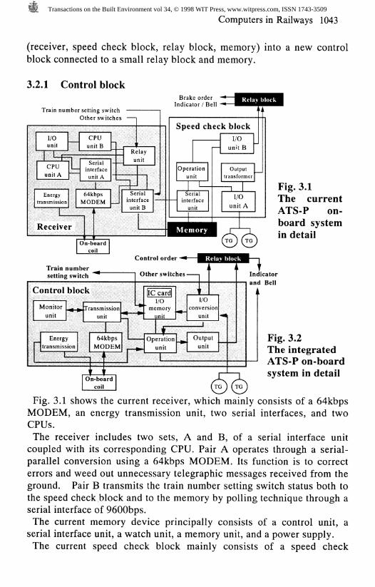
Fig.2.2Configuration ofthe integrated on-board system
In pursuit of ATS-P cost reduction, the current on-board system wasrevamped. The redesign effort resulted in the integration of theseparate on-board system units which eliminated redundancy andreduced size and maintenance labor costs.The recently developed system, shown in Fig.2.2, integrates the
equipment which constituted the on-board system described before
Transactions on the Built Environment vol 34, © 1998 WIT Press, www.witpress.com, ISSN 1743-3509
Computers in Railways 1043
(receiver, speed check block, relay block, memory) into a new controlblock connected to a small relay block and memory.
3.2.1 Control blockBrake order
Indicator/ Bell
tra
R
Othe
I/Ounit
CPUunit A
- —
L
Cun
inteun
Energynsmission
}1
eceiver
64kMOI
On-bCO
r switche
PUitB
:rialrfaceit Atbps)EM
—
^" Reu
=1-
laynit
Serialinterfacunit B
oardil
e
I
Spe<
Operun|Se
UI1-
Men
ed ch
itionit
1ialfacelit
eck blcI/C
unit
Outtransfc
1I/
uni
lory 1A(TG }
'
>ck) JB
3Ut>rmer
13t A
A(roj
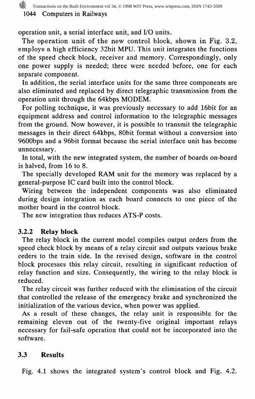
Fig. 3.1The currentATS-P on-board systemin detail
Train numbersetting switch
Control order -
Other switches - Indicatorand Bell
Fig. 3.2The integratedATS-P on-boardsystem in detail
Fig. 3.1 shows the current receiver, which mainly consists of a 64kbpsMODEM, an energy transmission unit, two serial interfaces, and twoCPUs.
The receiver includes two sets, A and B, of a serial interface unitcoupled with its corresponding CPU. Pair A operates through a serial-parallel conversion using a 64kbps MODEM. Its function is to correcterrors and weed out unnecessary telegraphic messages received from theground. Pair B transmits the train number setting switch status both tothe speed check block and to the memory by polling technique through aserial interface of 9600bps.The current memory device principally consists of a control unit, a
serial interface unit, a watch unit, a memory unit, and a power supply.The current speed check block mainly consists of a speed check
Transactions on the Built Environment vol 34, © 1998 WIT Press, www.witpress.com, ISSN 1743-3509
1044 Computers in Railways
operation unit, a serial interface unit, and I/O units.
The operation unit of the new control block, shown in Fig. 3.2,employs a high efficiency 32bit MPU. This unit integrates the functionsof the speed check block, receiver and memory. Correspondingly, onlyone power supply is needed; three were needed before, one for eachseparate component.
In addition, the serial interface units for the same three components arealso eliminated and replaced by direct telegraphic transmission from theoperation unit through the 64kbps MODEM.For polling technique, it was previously necessary to add 16bit for an
equipment address and control information to the telegraphic messagesfrom the ground. Now however, it is possible to transmit the telegraphicmessages in their direct 64kbps, SObit format without a conversion into9600bps and a 96bit format because the serial interface unit has becomeunnecessary.In total, with the new integrated system, the number of boards on-board
is halved, from 16 to 8.The specially developed RAM unit for the memory was replaced by a
general-purpose 1C card built into the control block.Wiring between the independent components was also eliminated
during design integration as each board connects to one piece of themother board in the control block.The new integration thus reduces ATS-P costs.
3.2.2 Relay blockThe relay block in the current model compiles output orders from the
speed check block by means of a relay circuit and outputs various brakeorders to the train side. In the revised design, software in the controlblock processes this relay circuit, resulting in significant reduction ofrelay function and size. Consequently, the wiring to the relay block isreduced.The relay circuit was further reduced with the elimination of the circuit
that controlled the release of the emergency brake and synchronized theinitialization of the various device, when power was applied.As a result of these changes, the relay unit is responsible for the
remaining eleven out of the twenty-five original important relaysnecessary for fail-safe operation that could not be incorporated into thesoftware.
3.3 Results
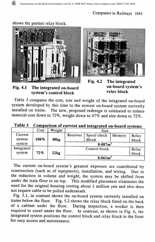
Fig. 4.1 shows the integrated system's control block and Fig. 4.2.
Transactions on the Built Environment vol 34, © 1998 WIT Press, www.witpress.com, ISSN 1743-3509
Computers in Railways 1045
shows the partner relay block.
Fig. 4.2
Fig. 4.1 The integrated on-boardsystem's control block
The integratedon-board system'srelay block
Table 3 compares the cost, size and weight of the integrated on-boardsystem developed by this time to the newest on-board system currentlyinstalled on trains. The new, proposed redesign is estimated to reducematerial cost down to 72%, weight down to 47% and size down to 72%.
Table 3 Comparison of current and integrated on-board systems
Currentnewestsystem
Integratedsystem
Cost
100%
72%
Weight
48kg
22kg
SizeReceiver Speed check
BlockMemory Relay
block0.087m'
Control block Relayblock
0.061m'
The current on-board system's greatest expenses are contributed byconstruction (such as of equipment), installation, and wiring. Due tothe reduction in volume and weight, the system may be shifted fromunder the train floor to on top. This modified placement eliminates theneed for the original housing costing about 1 million yen and also doesnot require cable to be pulled underneath.
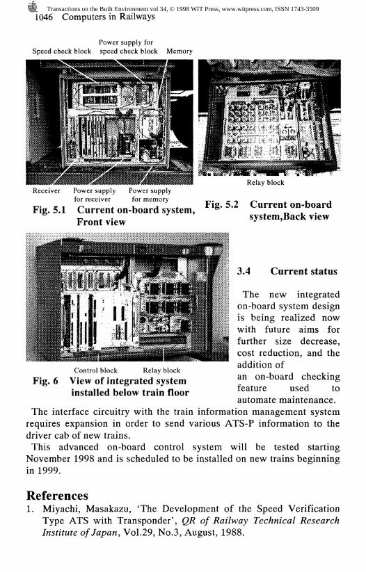
Fig. 5.1, in contrast shows the on-board system currently installed ontrains below the floor. Fig. 5.2 shows the relay block fitted on the backof a cabinet under the floor. During inspection, a worker is thenrequired to crawl under the floor. In contrast, as shown in Fig. 6, theintegrated system positions the control block and relay block to the frontfor easy access and maintenance.
Transactions on the Built Environment vol 34, © 1998 WIT Press, www.witpress.com, ISSN 1743-3509
1046 Computers in Railways
Power supply forSpeed check block speed check block Memory
Receiver Power supply Power supplyfor receiver for memory
Fig. 5.1 Current on-board system,Front view
Control block Relay blockFig. 6 View of integrated system
installed below train floor
Relay block
Fig. 5.2 Current on-boardsystem,Back view
3.4 Current status
The new integratedon-board system designis being realized nowwith future aims forfurther size decrease,cost reduction, and theaddition ofan on-board checkingfeature used toautomate maintenance.
The interface circuitry with the train information management systemrequires expansion in order to send various ATS-P information to thedriver cab of new trains.This advanced on-board control system will be tested startingNovember 1998 and is scheduled to be installed on new trains beginningin 1999.
References1. Miyachi, Masakazu, 'The Development of the Speed Verification
Type ATS with Transponder', QR of Railway Technical ResearchInstitute of Japan, Vol.29, No.3, August, 1988.
Transactions on the Built Environment vol 34, © 1998 WIT Press, www.witpress.com, ISSN 1743-3509