Embed Size (px)
Citation preview

Concept design and hydrodynamic optimizationof an innovative SWATH USV by CFD methods
Stefano Brizzolara & Tom Curtin & Marco Bovio &
Giuliano Vernengo
# Springer-Verlag 2011
Abstract The paper presents the main characteristics of aninnovative platform which has been conceived anddesigned to extend the operational capabilities of currentunmanned surface vehicles in terms of platform stability inwaves and of powering requirement at a relatively highspeed. The main idea which rules the project is therealization of a small autonomous surface unit (about 6 min length) capable of undertaking several tasks in themarine environment even with moderate rough sea con-ditions. The designed vessel has the ability to locate,recover, and launch other members of the autonomous fleet(like AUVs or other underwater devices) and at the sametime could carry out a surveillance service of the surround-ing areas. To manage these tasks, the vehicle is designed toprovide a fairly good autonomy which is needed to faceintermediate-range missions (100 nautical miles). Thechoice of a small waterplane area twin hull (SWATH) form
has been motivated by its excellent properties of seakeepingqualities, combined with a non-conventional low resistanceunderwater hull shape, currently under patenting process,which is able to reduce to a minimum the resistance of thevessel especially at higher speeds. To obtain the mostefficient profile of the underwater bodies, a systematicoptimization with an automatic procedure based on aparametric definition of the geometry, a state-of-the-artcomputational fluid dynamics (CFD) flow solver, and adifferential evolution global minimization algorithm havebeen created and used. As expected, all the final CFDcomputations on the best design have demonstrated thesuperior efficiency of the developed unconventionalSWATH technology with respect to different alternativesof current hull typologies.
Keywords SWATH .Hydrodynamic optimization . CFDnumerical simulations . Autonomous vehicle
1 Introduction
The high cost related to the operational needs of oceano-graphic vessel and the maturity achieved both by unmannedsurface (USV) and underwater (UUV) vehicles suggest therealization of coastal monitoring systems based on a net ofautonomous cooperating vehicles (Curtin et al. 1993, 2001,2005; Bovio et al. 2001). These systems are extremely usefulfor in situ measurements required for predicting differentoceanographic phenomena and, at the same time, areessential to carry out underwater/surface combined patrollingand surveillance aimed, for instance, to the discovery ofaccidental dangerous events, such as pollutant, but also tothe detection of explosive hazards, terrorist attacks, etc.
Responsible Editor: Michel Rixen
This article is part of the Topical Collection on Maritime RapidEnvironmental Assessment
S. Brizzolara (*) :G. VernengoDepartment of Naval Architecture,Marine and Electrical Engineering, University of Genoa,Genoa, Italye-mail: [email protected]
T. CurtinN.A.T.O. Undersea Research Centre,La Spezia, Italy
M. BovioDepartment of Naval Architecture,Marine and Electrical Engineering, Undersea Research Centre,La Spezia, Italy
Ocean Dynamics (2012) 62:227–237DOI 10.1007/s10236-011-0471-y
Received: 25 February 2011 /Accepted: 29 June 2011 /Published online: 23 September 2011
In this context, NURC, the NATO Undersea ResearchCenter in La Spezia (Italy), started a collaboration with theMarine CFDGroup of the University of Genova to develop aninnovative design for a multipurpose autonomous surfacevehicle that is believed will be the key element to realize anefficient integrated network of autonomous underwatervehicles that can be served, charged, and managed by thenew surface vehicle. Figure 1 depicts an aspect of thisconcept related to the communication. For the USV to beefficient, it should be relatively small (affordable, manage-able, and easy to transport and operate) and with a goodoperational capabilities also in relatively rough seas.
To achieve the desired characteristics, a small waterplanearea twin hull (SWATH) type has been chosen because ofits excellent properties of seakeeping, which guarantee agood platform stability even in relatively rough seas (seastate 3 in relation to the dimension of the proposed vehicle).Several SWATH vessels for different applications have beendesigned in the past, but the common characteristic is that thedisplacement necessary to keep the ship afloat is located wellbelow the free surface, where it is less affected by waveaction. The main principle is that a reduction in motionexciting forces is achieved through the very limited variationof buoyancy due to the change of submerged volume of thestruts when an incident wave is passing by the hull. Thisvariation of volume, which directly depends on the shape ofthe hull around the design waterline, is minimized in aSWATH vessel with respect to equivalent monohull or also
catamarans and hence also induced forces andmoments. Also,other wave exciting components, such as Froude–Krylovforces, are exponentially diminished as depth increases(deeply submerged submarines are not affected by waveaction at all). To extremely simplify, in fact, placing themajority of a ship's displacement under the waves is similarin concept to creating a ship that rides atop twin submarines.The consequence is the possibility to deliver a platformsteadiness and ride quality typical of a large ship in a muchsmaller vessel and the consequent ability to operate andsustain a higher cruising speed in rough seas.
On the other hand, the advantage in superior seakeepingof SWATH vessels is normally balanced by a lowerefficiency in terms of advance resistance in calm water,their wetted surface being larger than equivalent conven-tional hull forms. Nevertheless, playing with the geometryof the immersed part of the hull, it is possible to reduce thewave resistance, aiming for a positive interference effectbetween the generated wave trains, eventually minimizingthe requested propulsion power to reach the given designspeed (Papanikolaou and Androulakakis 1991; Salvesen etal. 1985; Schellin and Papanikolaou 1991). The optimiza-tion of the shape of the underwater hulls for resistance is aquite important point in the design of an efficient USVvessel since the propulsion powering requirement and,consequently, the fuel consumption or the autonomy rangeare essential features for the operation of these types ofvehicles.
Fig. 1 Integrated cooperative UUV–USV network: the small USV-SWATH is the key element
228 Ocean Dynamics (2012) 62:227–237
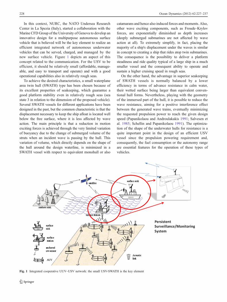
In the present study, a numerical, fully automatic,computer-based parametric optimization procedure devisedon the basis of an original scheme already applied withsuccess in the past (Brizzolara 2004) is enhanced andactualized for the case with modern parametric geometrygeneration modules and optimization algorithms, similar tothose recently developed and succesfully applied in the caseof other hull form optimization problems (Brizzolara et al.2010; Biliotti et al., 2010). The result is the unconventionalhull for the ASV presented in Fig. 2, with its main featuresdescribed in the next section.
This optimization procedure is described in Section 3,while the last chapter gives the assessment of the hydrody-namic performance of the vessel obtained with a state-of-the-art computational fluid dynamics (CFD) code, able to solvethe viscous-free surface full-scale flow around the hull.
2 Layout and general arrangement
The limited main dimensions of the vessel are influencedby some key requirements:
– The ability to cover the assigned range at design speedwith onboard fuel and power generation and conver-sion devices
– The ability of storing, recharging, and releasingautonomous underwater vehicles (AUVs) of lengthsup to 2.2 m and maximum weights of about 100 kg
– Transportability inside a standard container (ISO LWH
12.2 × 2.44 × 2.59)
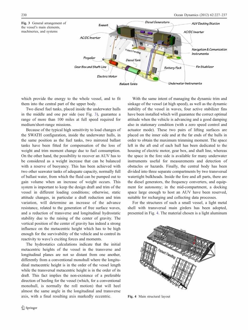
Consequently, since the very beginning of the project, adismountable aluminum alloy structure, represented inFig. 4, has been designed to satisfy the imposed constraints.
The optimized vessel configuration, currently underpatenting process (Brizzolara 2011a, b), is basicallycomposed of a main central body with its keel linesuspended almost 1 m above sea level and by two couples
of vertical struts that connect to the underwater hulls. Thecoupling is obtained by junctions between the top of thestruts and the side of the main body which can be openedfor the packing process; in addition, a system of rods,which link the bottom of the main body with the side of thestruts, avoids the relative rotation of the structure aroundthe joints.
An iterative approach has been followed to converge to thedefinitive version of the designed vessel. This iterative designprocedure is typical in naval architecture where the design,despite a few parameters fixed as constraints, changesconstantly under the influence of boundary conditions thatstep by step will lead to a more accurate configuration. Theprocess is definitely nonlinear and can be then imagined as aspiral in which all the steps have to be repeated in order tonarrow down the domain of the input variables and toconverge to the best compromise solution that is able torespect hydrostatic equilibrium and stability, strength, andpayload capacity while optimizing hull form and propulsionsystem shape for resistance and seakeeping.
So with the few given data known for the preliminaryconfiguration, performance prediction and weight estima-tion, followed by a stability check, have been performed tobetter understand the power required for the propulsionsystem of the vessel and its seakeeping qualities. Then,after an evaluation of the obtained results, some changeswere introduced to improve the vessel’s characteristics,which means that the analysis has to be repeated againseveral times. The iterative process finally brought a morestable and efficient configuration with the layout optimizedfor resistance and stability, depicted in Fig. 2.
Having set the main dimensions and components, it waspossible to identify the general arrangement of thecomponents inside the structure (Fig. 3) in order to betterdefine static moments and the qualitative position of thecenter of gravity. Moreover, with the estimated requiredpropulsion power of 39 kW at the design speed, it has beendecided to install two diesel generators each of 22 kW,
Fig. 2 External view and maincharacteristics of the unconven-tional SWATH ASV design andhence valid to estimate theoptimized total advanceresistance
Ocean Dynamics (2012) 62:227–237 229
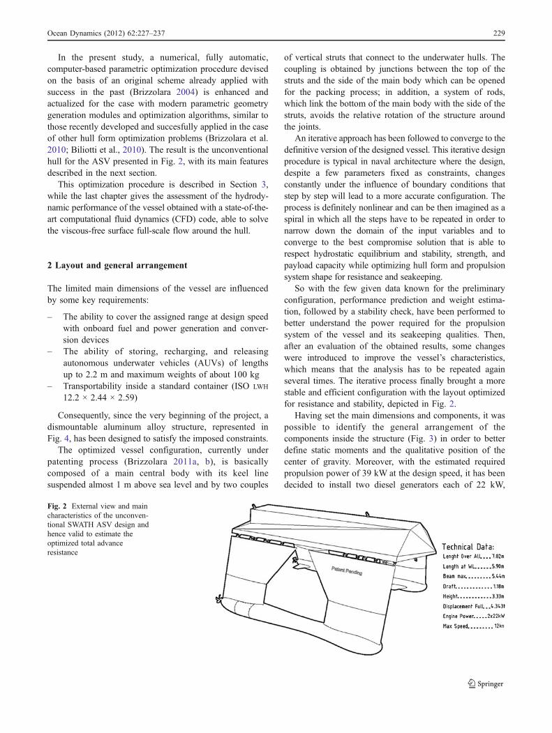
which provide the energy to the whole vessel, and to fitthem into the central part of the upper body.
Two diesel fuel tanks, placed inside the underwater hullsin the middle and one per side (see Fig. 3), guarantee arange of more than 100 miles at full speed required formedium/short-range missions.
Because of the typical high sensitivity to load changes ofthe SWATH configuration, inside the underwater hulls, inthe same position as the fuel tanks, two mirrored ballasttanks have been fitted for compensation of the loss ofweight and trim moment change due to fuel consumption.On the other hand, the possibility to recover an AUV has tobe considered as a weight increase that can be balancedwith a reserve of buoyancy. This has been achieved withtwo other seawater tanks of adequate capacity, normally fullof ballast water, from which the fluid can be pumped out togain volume when an increase of weight occurs. Thissystem is important to keep the design draft and trim of thevessel in different loading conditions; otherwise, staticattitude changes, in particular a draft reduction and trimvariation, will determine an increase of the advanceresistance, related to the generation of free surface waves,and a reduction of transverse and longitudinal hydrostaticstability due to the raising of the center of gravity. Thevertical position of the center of gravity has indeed a stronginfluence on the metacentric height which has to be highenough for the survivability of the vehicle and to control itsreactivity to wave’s exciting forces and moments.
The hydrostatics calculations indicate that the initialmetacentric heights of the vessel in the transverse andlongitudinal planes are not so distant from one another,differently from a conventional monohull where the longitu-dinal metacentric height is in the order of the vessel lengthwhile the transversal metacentric height is in the order of itsdraft. This fact implies the non-existence of a preferabledirection of heeling for the vessel (which, for a conventionalmonohull, is normally the roll motion) that will heelalmost the same angle in the longitudinal and transverseaxis, with a final resulting axis markedly eccentric.
With the same intent of managing the dynamic trim andsinkage of the vessel (at high speed), as well as the dynamicstability of the vessel in waves, four active stabilizer finshave been installed which will guarantee the correct optimalattitude when the vehicle is advancing and a good dampingalso in stationary condition (with a zero speed control andactuator mode). These two pairs of lifting surfaces areplaced on the inner side and at the far ends of the hulls inorder to obtain the maximum trimming moment. The spaceleft in the aft end of each hull has been dedicated to thehousing of electric motor, gear box, and shaft line, whereasthe space in the fore side is available for many underwaterinstruments useful for measurements and detection ofobstacles or hazards. Finally, the central body has beendivided into three separate compartments by two transversalwatertight bulkheads. Inside the fore and aft parts, there arethe diesel generators, the frequency converters, and equip-ment for autonomy; in the mid-compartment, a dockingspace large enough to host an AUV have been reserved,suitable for recharging and collecting data processes.
For the structures of such a small vessel, a light metalshell with transversal main girders has been adopted,presented in Fig. 4. The material chosen is a light aluminum
Fig. 3 General arrangement ofthe vessel’s main elements,machineries, and systems
Fig. 4 Main structural layout
2 Ocean Dynamics (2012) 62:227–23730
alloy, such as 5083 H321, having a specific weight of about2.7 kg/dm3. A special cradle composed of articulatedtransversal main structural elements, connected to the twomain longitudinal girders by means of resilient supports,has been designed for the foundation of the two dieselgenerators. By this special arrangement, the vibrationinduced by the diesel engines will experience high dampingin their propagation to surrounding structures, enhancingthe silence of the vessel for the best air and water noisemeasurements. Watertight dismountable openings havebeen designed to guarantee the access of the electric motorsin the underwater hull and other components in the struts.The weight of the vessel’s outer shell and that of thereinforcing structures was estimated on the basis of theactual metal volume of the structures as designed in the 3Dmodel, as shown in the arrangement in Fig. 4.
As anticipated, stability resulted to be a very crucial itemof the whole project. Although the SWATH configurationoffers superior seakeeping qualities, the hydrostatic stabilityindex has to be evaluated very carefully because of the highsensitivity of this vessel to weight variations in terms of itsmagnitude and change in position. Particular attention hasbeen paid to match the longitudinal position of the center ofbuoyancy and the center of gravity (LCB–LCG), with somereserve given by additional ballast water tanks since a verylittle gap of the relative position between this two centersdetermines an important change of the longitudinal trimangle. This happens as a consequence of the slender geometryof the struts in the horizontal plane, which is characterized bya very little waterplane area, that do not offer a large amount ofbuoyancy reserve which can counterbalance weight changes.The solution adopted to avoid the problem has been to taperthe struts just above the waterplane, increasing width andlength, in order to gain volume in case a pitching momentoccurs. The same solution have been adopted for forces and
moments which can act in the transversal plane, and a detailedanalysis of the transversal stability was performed with regardto the side area exposed out of the water, being larger than thefrontal one.
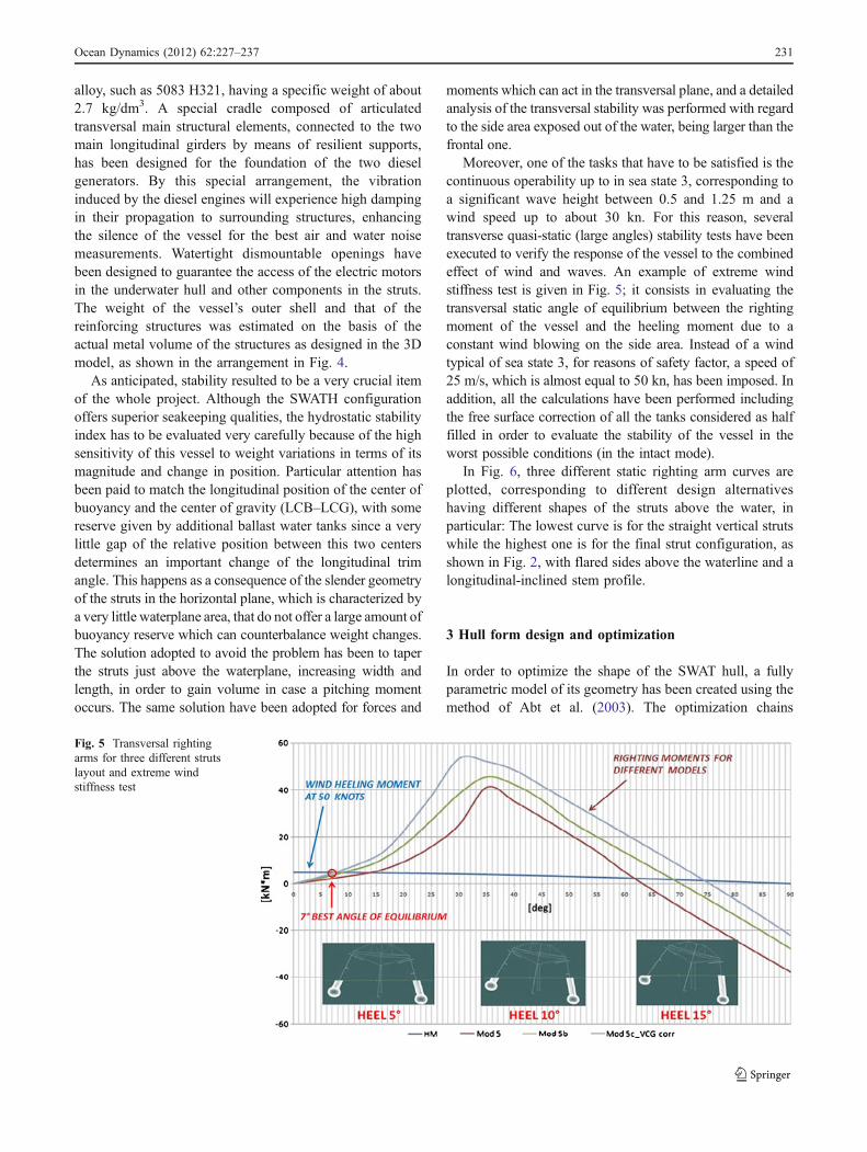
Moreover, one of the tasks that have to be satisfied is thecontinuous operability up to in sea state 3, corresponding toa significant wave height between 0.5 and 1.25 m and awind speed up to about 30 kn. For this reason, severaltransverse quasi-static (large angles) stability tests have beenexecuted to verify the response of the vessel to the combinedeffect of wind and waves. An example of extreme windstiffness test is given in Fig. 5; it consists in evaluating thetransversal static angle of equilibrium between the rightingmoment of the vessel and the heeling moment due to aconstant wind blowing on the side area. Instead of a windtypical of sea state 3, for reasons of safety factor, a speed of25 m/s, which is almost equal to 50 kn, has been imposed. Inaddition, all the calculations have been performed includingthe free surface correction of all the tanks considered as halffilled in order to evaluate the stability of the vessel in theworst possible conditions (in the intact mode).
In Fig. 6, three different static righting arm curves areplotted, corresponding to different design alternativeshaving different shapes of the struts above the water, inparticular: The lowest curve is for the straight vertical strutswhile the highest one is for the final strut configuration, asshown in Fig. 2, with flared sides above the waterline and alongitudinal-inclined stem profile.
3 Hull form design and optimization
In order to optimize the shape of the SWAT hull, a fullyparametric model of its geometry has been created using themethod of Abt et al. (2003). The optimization chains
Fig. 5 Transversal rightingarms for three different strutslayout and extreme windstiffness test
Ocean Dynamics (2012) 62:227–237 231
derived from the method were first devised and appliedwith success for SWATH hulls by Brizzolara (2004) with adifferent mathematical representation of the underwaterbodies. The main concept behind the parametric optimiza-tion is to define a limited set of free variable parameters bywhich it is possible to change, and hence control, thegeometry which has been modeled. In this new study, twoseparate models have been constructed: one for thesubmerged hull and one for the struts.
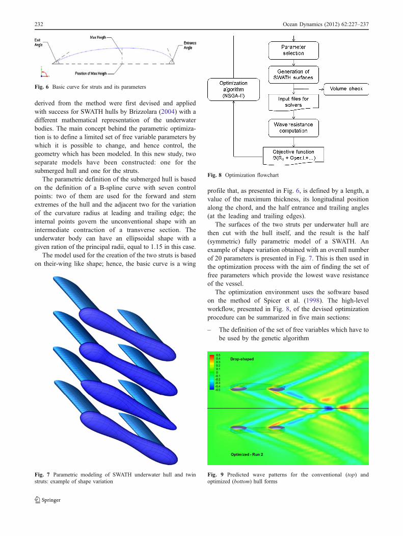
The parametric definition of the submerged hull is basedon the definition of a B-spline curve with seven controlpoints: two of them are used for the forward and sternextremes of the hull and the adjacent two for the variationof the curvature radius at leading and trailing edge; theinternal points govern the unconventional shape with anintermediate contraction of a transverse section. Theunderwater body can have an ellipsoidal shape with agiven ration of the principal radii, equal to 1.15 in this case.
The model used for the creation of the two struts is basedon their-wing like shape; hence, the basic curve is a wing
profile that, as presented in Fig. 6, is defined by a length, avalue of the maximum thickness, its longitudinal positionalong the chord, and the half entrance and trailing angles(at the leading and trailing edges).
The surfaces of the two struts per underwater hull arethen cut with the hull itself, and the result is the half(symmetric) fully parametric model of a SWATH. Anexample of shape variation obtained with an overall numberof 20 parameters is presented in Fig. 7. This is then used inthe optimization process with the aim of finding the set offree parameters which provide the lowest wave resistanceof the vessel.
The optimization environment uses the software basedon the method of Spicer et al. (1998). The high-levelworkflow, presented in Fig. 8, of the devised optimizationprocedure can be summarized in five main sections:
– The definition of the set of free variables which have tobe used by the genetic algorithm
Fig. 7 Parametric modeling of SWATH underwater hull and twinstruts: example of shape variation
Fig. 6 Basic curve for struts and its parameters
Fig. 8 Optimization flowchart
Fig. 9 Predicted wave patterns for the conventional (top) andoptimized (bottom) hull forms
232 Ocean Dynamics (2012) 62:227–237
– A first tentative geometry of the SWATH is created.– A check on volume constraint is performed and, in
order to speed up the process, no CFD calculation is donefor any geometry that does not respect this constraint,which is referred to as an unfeasible design case.
– Then, for all feasible designs (i.e., those that respect theimposed constraints), the calculation of wave resistancevalues is carried out by means of the boundary elementmethod, as first introduced in Brizzolara (2004).
– The last step is the section for processing the resultsobtained in the output of the CFD calculations, mainlyaimed at the evaluation of the objective function(wave resistance in this case).
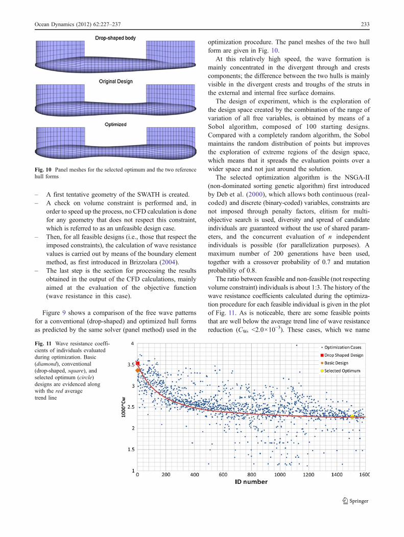
Figure 9 shows a comparison of the free wave patternsfor a conventional (drop-shaped) and optimized hull formsas predicted by the same solver (panel method) used in the
optimization procedure. The panel meshes of the two hullform are given in Fig. 10.
At this relatively high speed, the wave formation ismainly concentrated in the divergent through and crestscomponents; the difference between the two hulls is mainlyvisible in the divergent crests and troughs of the struts inthe external and internal free surface domains.
The design of experiment, which is the exploration ofthe design space created by the combination of the range ofvariation of all free variables, is obtained by means of aSobol algorithm, composed of 100 starting designs.Compared with a completely random algorithm, the Sobolmaintains the random distribution of points but improvesthe exploration of extreme regions of the design space,which means that it spreads the evaluation points over awider space and not just around the solution.
The selected optimization algorithm is the NSGA-II(non-dominated sorting genetic algorithm) first introducedby Deb et al. (2000), which allows both continuous (real-coded) and discrete (binary-coded) variables, constraints arenot imposed through penalty factors, elitism for multi-objective search is used, diversity and spread of candidateindividuals are guaranteed without the use of shared param-eters, and the concurrent evaluation of n independentindividuals is possible (for parallelization purposes). Amaximum number of 200 generations have been used,together with a crossover probability of 0.7 and mutationprobability of 0.8.
The ratio between feasible and non-feasible (not respectingvolume constraint) individuals is about 1:3. The history of thewave resistance coefficients calculated during the optimiza-tion procedure for each feasible individual is given in the plotof Fig. 11. As is noticeable, there are some feasible pointsthat are well below the average trend line of wave resistancereduction (CW, <2.0×10
−3). These cases, which we name
Fig. 10 Panel meshes for the selected optimum and the two referencehull forms
Fig. 11 Wave resistance coeffi-cients of individuals evaluatedduring optimization. Basic(diamond), conventional(drop-shaped, square), andselected optimum (circle)designs are evidenced alongwith the red averagetrend line
Ocean Dynamics (2012) 62:227–237 233
fake design, do correspond to valid 3D geometries respect-ing the volume constraint (feasible designs), but theirpanel meshes are incorrectly generated, normallycorresponding to a faulty irregular shape of the struts. Theresult of the calculation of these points is an unrealisticallylow wave resistance that, unfortunately, the automaticprocedure is not able to recognize and discard. The presenceof these points, though, does not compromise the conver-gence, and they can be hence checked and discarded aposteriori.
A rather good and fast convergence of the geneticalgorithm is reached after about 4,000 evaluations, asclearly visible from the average trend line in Fig. 11,interpolating the history of the objective function evaluatedfor the different feasible design alternatives.
Due to the large separation of the two underwater hulls(s/L=0.75), no particular interference effects are expectedbetween the wave trains generated by each demi-hull. Thisis confirmed by the results of Fig. 12 which presents thepredicted wave resistance coefficients for the basic, theconventional (drop-shaped), and the optimized hull formsas a function of the transversal separation of the two demi-hulls non-dimensionalized on the hull length (s/L). Thetwin hull interference factor calculated for the optimum hullshape, in fact, is even slightly higher than the referencehulls forms, at the design s/L=0.775.
The reduction of wave resistance achieved by theoptimum hull, in fact, comes exclusively from the positiveinterference between the wave trains generated by thecomponents of each demi-hull even in isolation. In thisdesign case, the proper calibration of the longitudinalpositions of the intermediate contracted section and of theother two maximum area sections plays a major role in thewave interference (cancelation) effects.
4 Estimation of hull resistance and propulsion power
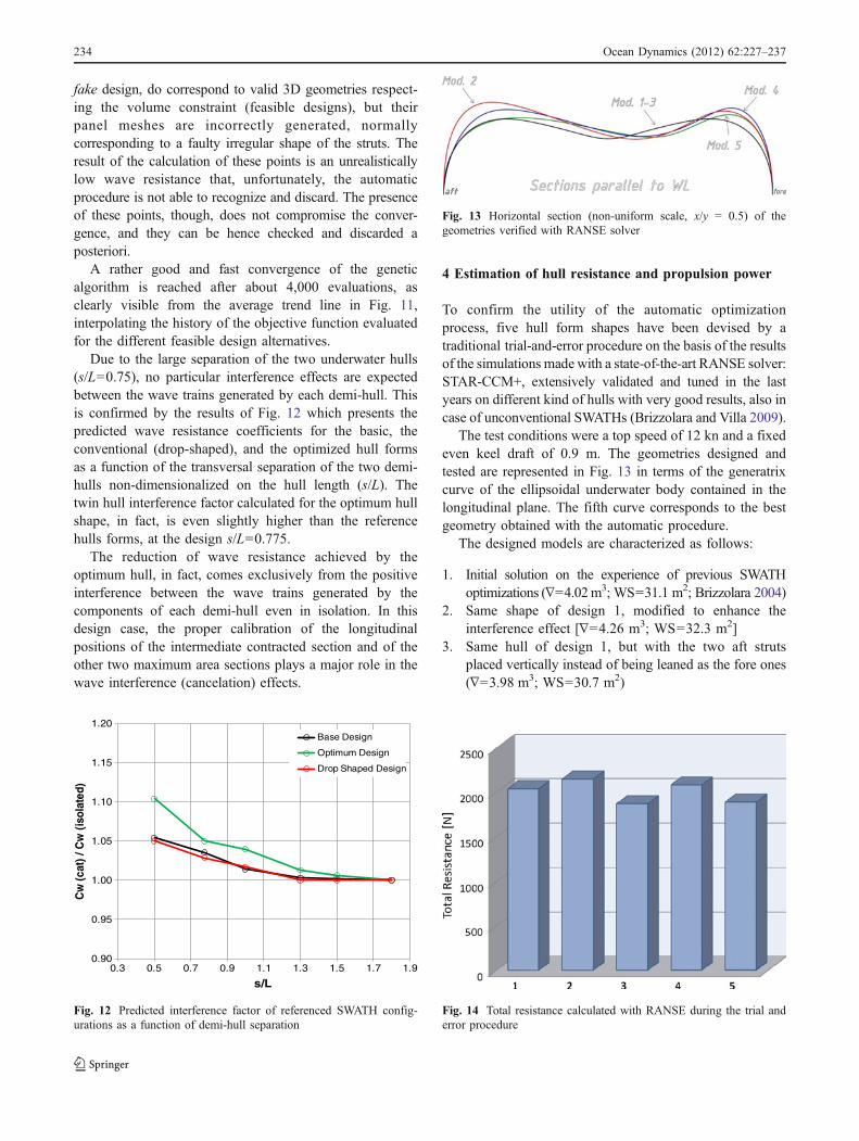
To confirm the utility of the automatic optimizationprocess, five hull form shapes have been devised by atraditional trial-and-error procedure on the basis of the resultsof the simulations made with a state-of-the-art RANSE solver:STAR-CCM+, extensively validated and tuned in the lastyears on different kind of hulls with very good results, also incase of unconventional SWATHs (Brizzolara and Villa 2009).
The test conditions were a top speed of 12 kn and a fixedeven keel draft of 0.9 m. The geometries designed andtested are represented in Fig. 13 in terms of the generatrixcurve of the ellipsoidal underwater body contained in thelongitudinal plane. The fifth curve corresponds to the bestgeometry obtained with the automatic procedure.
The designed models are characterized as follows:
1. Initial solution on the experience of previous SWATHoptimizations (∇=4.02m3; WS=31.1 m2; Brizzolara 2004)
2. Same shape of design 1, modified to enhance theinterference effect [∇=4.26 m3; WS=32.3 m2]
3. Same hull of design 1, but with the two aft strutsplaced vertically instead of being leaned as the fore ones(∇=3.98 m3; WS=30.7 m2)
Fig. 13 Horizontal section (non-uniform scale, x/y = 0.5) of thegeometries verified with RANSE solver
0.90
0.95
1.00
1.05
1.10
1.15
1.20
0.3 0.5 0.7 0.9 1.1 1.3 1.5 1.7 1.9
Cw
(cat
) / C
w (
isol
ated
)
s/L
Base Design
Optimum Design
Drop Shaped Design
Fig. 12 Predicted interference factor of referenced SWATH config-urations as a function of demi-hull separation
Fig. 14 Total resistance calculated with RANSE during the trial anderror procedure
2 Ocean Dynamics (2012) 62:227–23734
4. Other designed by experience (∇=4.05 m3; WS=31.5 m2)5. Optimum solution obtained with the automatic optimi-
zation process based on panel method (∇=4.148 m3;WS=31.999 m2)
Where ∇ is the displaced volume and WS is the wettedsurface in static condition.
As is clear from Fig. 14, where the total resistancepredicted by the RANSE solver is presented, excludingcase 3 that has different canting angles between the forwardand aft pairs of struts, model 5, obtained from theoptimization procedure, has been confirmed to be the bestsolution in terms of lower resistance. This result confirmstwo facts: The automatic parametric optimization procedureis more effective than a traditional trial-and-error procedure(that moreover took about 1 week instead of 1.5 days);secondly, the optimization with regard to wave resistanceonly can be in any case valid (with a limitation on theleading and trailing edge radii) to diminishing of the total
5
6
7
8
10
12
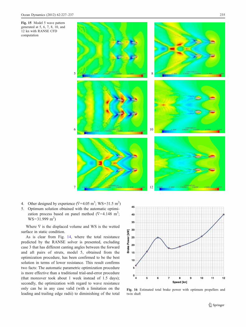
Fig. 15 Model 5 wave patterngenerated at 5, 6, 7, 8, 10, and12 kn with RANSE CFDcomputation
0
5
10
15
20
25
30
35
40
45
4 5 6 7 8 9 10 11 12
Bra
ke P
ower
[kW
]
Speed [kn]
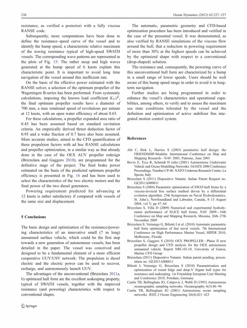
Fig. 16 Estimated total brake power with optimum propellers andtwin shaft
Ocean Dynamics (2012) 62:227–237 235
resistance, as verified a posteriori with a fully viscousRANSE code.
Subsequently, more computations have been done todefine the resistance–speed curve of the vessel and toidentify the hump speed, a characteristic relative maximumof the towing resistance typical of high-speed SWATHvessels. The corresponding wave patterns are represented inthe plots of Fig. 15: The rather steep and high wavesgenerated at the hump speed of 6 knots explain thischaracteristic point. It is important to avoid long timenavigation of the vessel around this inefficient rate.
On the basis of the effective power estimated with theRANSE solver, a selection of the optimum propeller of theWageningen B-series has been performed. From systematiccalculations, imposing the known load coefficient KT/J
2,the final optimum propeller results have a diameter of700 mm, a max rotational speed of revolutions per minuteat 12 knots, with an open water efficiency of about 0.65.
For these calculations, a propeller expanded area ratio of0.45 has been assumed based on standard cavitationcriteria. An empirically derived thrust deduction factor of0.95 and a wake fraction of 0.7 have also been assumed.More accurate studies, aimed to the CFD quantification ofthese propulsion factors with ad hoc RANSE calculationsand propeller optimization, in a similar way as that alreadydone in the case of the OEX AUV propeller redesign(Brizzolara and Gaggero 2010), are programmed for thedefinitive stage of the project. The final brake powerestimated on the basis of the predicted optimum propellerefficiency is presented in Fig. 16 and has been used toselect the characteristics of the two electric motors and thefinal power of the two diesel generators.
Powering requirement predicted for advancing at12 knots is rather satisfactory if compared with vessels ofthe same size and displacement.
5 Conclusions
The basic design and optimization of the resistance/power-ing characteristics of an innovative small (7 m long)unmanned surface vehicle, which could be the first steptowards a new generation of autonomous vessels, has beendetailed in the paper. The vessel was conceived anddesigned to be a fundamental element of a more efficientcooperative UUV/USV network: The propulsion is dieselelectric and the electric power can be used to recover,recharge, and autonomously launch UUV.
The advantages of the unconventional (Brizzolara 2011a,b) optimized hull form are the excellent seakeeping property,typical of SWATH vessels, together with the improvedresistance (and powering) characteristics with respect toconventional shapes.
The automatic, parametric geometry and CFD-basedoptimization procedure has been introduced and verified inthe case of the presented vessel. It was demonstrated, asalso verified by RANSE simulations of the viscous flowaround the hull, that a reduction in powering requirementof more than 30% at the highest speeds can be achievedby the optimized shape with respect to a conventional(drop-shaped) solution.
The resistance and, consequently, the powering curve ofthis unconventional hull form are characterized by a humpin a small range of lower speeds. Users should be wellaware of this hump speed range in order to avoid it in long-term navigation.
Further studies are being programmed in order toenhance the vessel’s characteristics and operational capa-bilities, among others, to verify and to assess the maximumsea state conditions tolerated by the vessel and thedefinition and optimization of active stabilizer fins inte-grated motion control system.
References
Abt C, Birk L, Harries S (2003) parametric hull design: theFRIENDSHIP-Modeler. International Conference on Ship andShipping Research—NAV 2003, Palermo, June 2003
Bovio E, Tyce R, Schmidt H (eds) (2001) Autonomous UnderwaterVehicle and Ocean Modelling Networks: GOATS 2000 ConferenceProceedings. Number CP-46. NATO Undersea Research Centre, LaSpezia, Italy
Brizzolara S (2011) Dispositivo Natante. Italian Patent Request no.GE2011A000011
Brizzolara S (2004) Parametric optimization of SWAT-hull forms by aviscous-inviscid free surface method driven by a differentialevolution algorithm. 25th Symposium on Naval Hydrodynamics,St. John’s, Newfoundland and Labrador, Canada, 8–13 August2004, vol V, pp 47–64
Brizzolara S, Villa D (2009) Numerical and experimental hydrody-namic performance of SLICE hull forms, NAV 2009—16thConference on Ship and Shipping Research, Messina, 26th–27thNovember 2009
Brizzolara S, Vernengo G, Biliotti I et al. (2010) Automatic parametrichull form optimization of fast naval vessels. 7th InternationalConference on High Performance Marine Vessel, HIPER 2010,Melbourne, Florida
Brizzolara S, Gaggero S (2010) OEX PROPELLER—Phase II newpropeller design and CFD analysis for the OEX autonomousunmanned vehicle. Report NRC-03-10, University of Genoa,Marine CFD Group
Brizzolara (2011) Dispositivo Natante. Italian patent pending, presen-tation no. GE2011A000011
Biliotti I, Vernengo G, Brizzolara S (2010) Parametrization andoptimization of round bilge and deep-V frigate hull types forresistance and seakeeping. 1st Friendship European User Meetingand Conference 2010, Potsdam, Germany
Curtin TB, Bellingham JG, Catipovic J, Webb D (1993) Autonomousoceanographic sampling networks. Oceanography 6(3):86–94
Curtin TB, Bellingham JG (2001) Autonomous ocean samplingnetworks. IEEE J Ocean Engineering 26(4):421–423
2 Ocean Dynamics (2012) 62:227–23736
Curtin TB, Crimmins DM, Curcio J, Benjamin M, Roper C (2005)Autonomous underwater vehicles: trends and transformations.Mar Tech Soc Journal 39(3):65–76
Deb K, Agrawal S, Pratap A, Meyarivan T (2000) A fast elitist non-dominated sorting genetic algorithm for multi-objective optimi-zation: NSGA-II. In: Schoenauer M et al (eds) Parallel problemsolving from nature. Springer, Paris, pp 849–858
Papanikolaou Α, Androulakakis Μ (1991) Hydrodynamic optimiza-tion of high-speed SWATH. Proceedings of 1st FAST '91Conference, Trondheim, Norway
Salvesen N, von Kerczek CH, Scragg CA, Cressy CP, Meinhold MJ(1985) Hydro-numeric design of SWATH ships. SNAME Trans-actions 93(1985):325–346
Schellin ΤΕ, Papanikolaou Α (1991) Prediction of seakeepingperformance of a SWATH-ship and comparison with measure-ments. Proceedings of the 1st FAST ‘91 Conference, Trondheim,Norway
Spicer D, Cook J, Poloni C, Sen P (1998) EP 20082 FRONTIER:industrial multiobjective design optimisation. ECCOMAS 98.Wiley, Chichester
Ocean Dynamics (2012) 62:227–237 237