Embed Size (px)
Citation preview
431
Concept, Design, and Prototyping of XSAS: A High Power Extendable Solar Array for CubeSat Applications
Patrick Senatore*, Andrew Klesh*, Thomas H. Zurbuchen*, Darren McKague* and James Cutler*
Abstract
CubeSats have proven themselves as a reliable and cost-effective method to perform experiments in space, but they are highly constrained by their specifications and size. One such constraint is the average continuous power, about 5 W, which is available to the typical CubeSat. To improve this constraint, we have developed the eXtendable Solar Array System (XSAS), a deployable solar array prototype in a CubeSat package, which can provide an average 23 W of continuous power. The prototype served as a technology demonstrator for the high risk mechanisms needed to release, deploy, and control the solar array. Aside from this drastic power increase, it is in the integration of each mechanism, their application within the small CubeSat form-factor, and the inherent passive control benefit of the deployed geometry that make XSAS a novel design. In this paper, we discuss the requirements and design process for the XSAS system and mechanical prototype, and provide qualitative and quantitative results from numerical simulations and prototype tests. We also discuss future work, including an upcoming NASA zero-gravity flight campaign, to further improve on XSAS and prepare it for future launch opportunities.
Introduction As the availability and frequency of CubeSat launches increase, it has become evident the CubeSats can provide opportunities to the scientific community that are either unprecedented or normally reserved for large, complex spacecraft. However, many such missions exceed the typical technical performance or overall constraints of CubeSats, such as their limited power and typical data-rates. In this paper, we present a novel solution to increase the continuous available power on a CubeSat bus from 5 W to 23 W through the use of a small, deployable solar array, which fits within CubeSat volume and mass constraints.
Background Extendable solar arrays from satellites have been extensively discussed in the literature. By the late 1960’s, work was being done to improve upon existing designs for deployable arrays [1] and several patents were in existence [2]. In the early 1980’s, flexible solar arrays were under study [3] and more consideration was given to innovative methods of deployment. Also, inflatable arrays were under consideration in the 1990’s [4]. Thus by the time CubeSats were conceived in the early part of the century, many types of deployable arrays had been successfully put into practice. Conforming to a rigid mass and volume standards [5], CubeSats provide a platform for very small (~1 kg, ~10-3 m3) and often secondary payloads. The CubeSat standard, the brainchild of Stanford University and the California Polytechnic University, is primarily used by universities, although their value is more broadly recognized by NASA, DOD, and also the traditional aerospace industry. The mass and volume standard enables launching out of a Poly Picosatellite Orbital Deployer (P-POD) or similar deployment mechanism, thus CubeSats substantially simplify the launch integration: The integrator is assured that the P-POD meets certain specifications for launch and the CubeSat has only minimal constraints placed upon it for safety and risk assurance. Since their conception, upwards of 25 CubeSats have been launched with
* University of Michigan, College of Engineering, Ann Arbor, MI
Proceedings of the 40th Aerospace Mechanisms Symposium, NASA Kennedy Space Center, May 12-14, 2010
NASA/CP-2010-216272
https://ntrs.nasa.gov/search.jsp?R=20100021926 2020-04-04T06:45:14+00:00Z
432
many more waiting for launch opportunities [6] covering many applications, from breakthrough science measurements to technology proving missions. CubeSats have very important limitations, affecting their breath of use. Most importantly, they have limited power, and must maintain a low mass to conform to the strict CubeSat specifications, which enable their simple integration and thus launch. Several technology developers are now addressing these restrictions through deployables, but their success is very limited after launch [7], [8], and no deployable CubeSat solar array of this type exists. In this paper, we describe the design, construction, testing, and future considerations for XSAS. We begin with design requirements, carry a design through modeling and prototype testing, continue with a discussion of the design, modeling and testing results of this innovative design, and end the paper with a description of ongoing work, which includes testing in microgravity through NASA’s Reduced Gravity Student Opportunities Program.
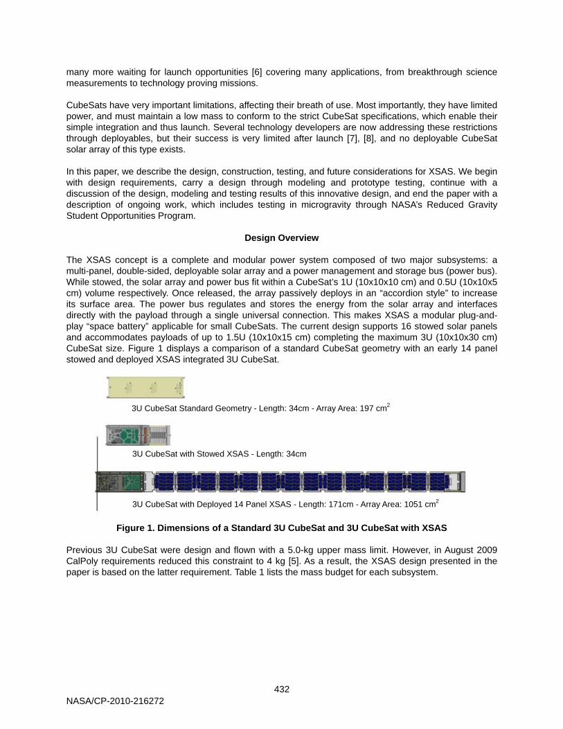
Design Overview The XSAS concept is a complete and modular power system composed of two major subsystems: a multi-panel, double-sided, deployable solar array and a power management and storage bus (power bus). While stowed, the solar array and power bus fit within a CubeSat’s 1U (10x10x10 cm) and 0.5U (10x10x5 cm) volume respectively. Once released, the array passively deploys in an “accordion style” to increase its surface area. The power bus regulates and stores the energy from the solar array and interfaces directly with the payload through a single universal connection. This makes XSAS a modular plug-and-play “space battery” applicable for small CubeSats. The current design supports 16 stowed solar panels and accommodates payloads of up to 1.5U (10x10x15 cm) completing the maximum 3U (10x10x30 cm) CubeSat size. Figure 1 displays a comparison of a standard CubeSat geometry with an early 14 panel stowed and deployed XSAS integrated 3U CubeSat.
Figure 1. Dimensions of a Standard 3U CubeSat and 3U CubeSat with XSAS
Previous 3U CubeSat were design and flown with a 5.0-kg upper mass limit. However, in August 2009 CalPoly requirements reduced this constraint to 4 kg [5]. As a result, the XSAS design presented in the paper is based on the latter requirement. Table 1 lists the mass budget for each subsystem.
3U CubeSat Standard Geometry - Length: 34cm - Array Area: 197 cm2
3U CubeSat with Stowed XSAS - Length: 34cm
3U CubeSat with Deployed 14 Panel XSAS - Length: 171cm - Array Area: 1051 cm2
NASA/CP-2010-216272
433
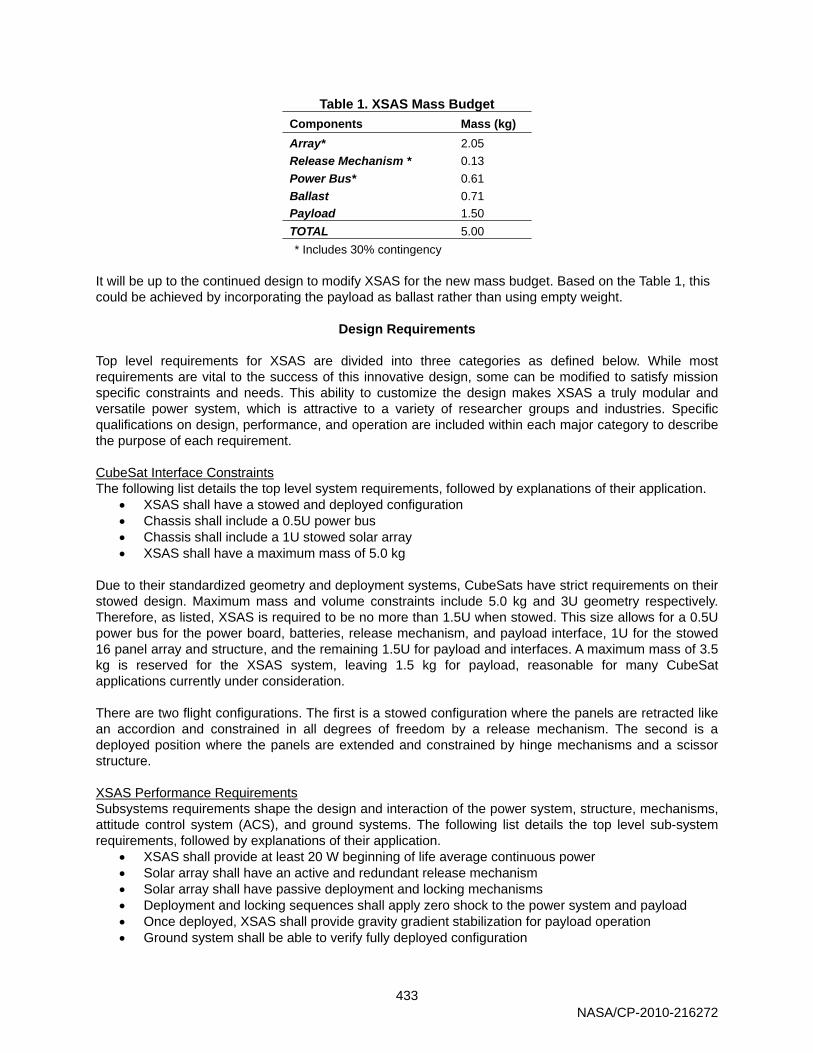
Table 1. XSAS Mass Budget Components Mass (kg) Array* 2.05 Release Mechanism * 0.13 Power Bus* 0.61 Ballast 0.71 Payload 1.50 TOTAL 5.00 * Includes 30% contingency
It will be up to the continued design to modify XSAS for the new mass budget. Based on the Table 1, this could be achieved by incorporating the payload as ballast rather than using empty weight.
Design Requirements
Top level requirements for XSAS are divided into three categories as defined below. While most requirements are vital to the success of this innovative design, some can be modified to satisfy mission specific constraints and needs. This ability to customize the design makes XSAS a truly modular and versatile power system, which is attractive to a variety of researcher groups and industries. Specific qualifications on design, performance, and operation are included within each major category to describe the purpose of each requirement. CubeSat Interface Constraints The following list details the top level system requirements, followed by explanations of their application.
• XSAS shall have a stowed and deployed configuration • Chassis shall include a 0.5U power bus • Chassis shall include a 1U stowed solar array • XSAS shall have a maximum mass of 5.0 kg
Due to their standardized geometry and deployment systems, CubeSats have strict requirements on their stowed design. Maximum mass and volume constraints include 5.0 kg and 3U geometry respectively. Therefore, as listed, XSAS is required to be no more than 1.5U when stowed. This size allows for a 0.5U power bus for the power board, batteries, release mechanism, and payload interface, 1U for the stowed 16 panel array and structure, and the remaining 1.5U for payload and interfaces. A maximum mass of 3.5 kg is reserved for the XSAS system, leaving 1.5 kg for payload, reasonable for many CubeSat applications currently under consideration. There are two flight configurations. The first is a stowed configuration where the panels are retracted like an accordion and constrained in all degrees of freedom by a release mechanism. The second is a deployed position where the panels are extended and constrained by hinge mechanisms and a scissor structure. XSAS Performance Requirements Subsystems requirements shape the design and interaction of the power system, structure, mechanisms, attitude control system (ACS), and ground systems. The following list details the top level sub-system requirements, followed by explanations of their application.
• XSAS shall provide at least 20 W beginning of life average continuous power • Solar array shall have an active and redundant release mechanism • Solar array shall have passive deployment and locking mechanisms • Deployment and locking sequences shall apply zero shock to the power system and payload • Once deployed, XSAS shall provide gravity gradient stabilization for payload operation • Ground system shall be able to verify fully deployed configuration
NASA/CP-2010-216272
434
Power system requirements impact the entire design of XSAS. While most CubeSat power requirements are limited to 5 W, XSAS shall supply 20 W of average continuous power during its sunlit orbit. As a result, its array needs to contain enough solar panels with highly efficient solar cells to produce this power. Additionally, the deployment mechanisms must be small enough to fit the required number of panels within the solar arrays 1U stowed volume budget. The release mechanism is required to be redundant, robust, and reliable. As an active system, testing and verification is vital to the performance validation. Therefore, for testing purposes, the release mechanism shall be simple, inexpensive, and repeatable with a 10 minutes maximum reset time. The hinge and deployment system must deploy the array passively, control the deployment rate, and lock the array into its open configuration. After initial estimates the entire hinge system is required to have less than a 3-mm height when folded in order to have enough vertical space for 16 solar panels. Hinge width and length also need to be minimized to ensure maximum available surface area, while still providing a reliable connection between panels. Finally, the performance of the array during deployment must be passively controlled at all times to eliminate shock on the structure and payload. This means additional mechanisms must be integrated to passively control the array’s deployment orientation and rate. Note the possibility of gravity gradient stabilization is an inherent quality of the deployed XSAS geometry in LEO. To take full advantage of this unique quality, the system’s passive pointing accuracy must be considered in the structural design, mass, and volume budget. Since passive pointing accuracy is controlled by the center of gravity of the deployed system, suitable volume must be allotted for ballast or additional functional mass at the top of the array. Mission specific requirements may have a major impact on the application of this design and shall be considered when sizing the ballast hardware. Fabrication Requirements Fabrication requirements control the cost budget and manufacturing time of XSAS. The following list details the top level sub-system requirements and is followed by explanations of their application.
• XSAS shall include all commercial off-the-shelf (COTS) components and materials • Any fabrication shall be done in house using available student accessible machinery • Fabrication of the final XSAS prototype shall be completed and tested within 3.5 months
The purpose of these requirements is to restrict the cost of manufacturing a complete XSAS system. By limiting the mechanisms to COTS parts and materials, engineers can focus on the custom and creative integration of these parts. Additionally, mechanisms and components can be rapidly prototyped for testing and production. Lead times of custom parts will not impact the manufacturing time of any XSAS subsystem.
Simulations
Analytical simulations and trade studies were required to determine the quantitative requirements and behavior of the XSAS solar array and gravity gradient system. The solar array was sized based on a trade study between two types of solar cells with average on orbit power losses. The gravity gradient analysis was also completed using simplified disturbance models and the projected geometry and mass distribution of the deployed XSAS and payload. The following sections describe the details of each trade study. Solar Cell Selection According to volume constrains, the XSAS array can have as many as 16 panels. To determine the maximum power capacity for this array, a trade study was completed comparing Spectrolab Triangular Advanced Solar Cells (TASC) and Emcore 2nd Generation Triple Junction (BTJ) cells. The most obvious difference is the efficiency and price of each cell. An array composed of TASC cells is half the cost of a BTJ array with an efficiency of 27±3% and 28.5% [10] [11], respectively. Immediately, the additional cost
NASA/CP-2010-216272
435
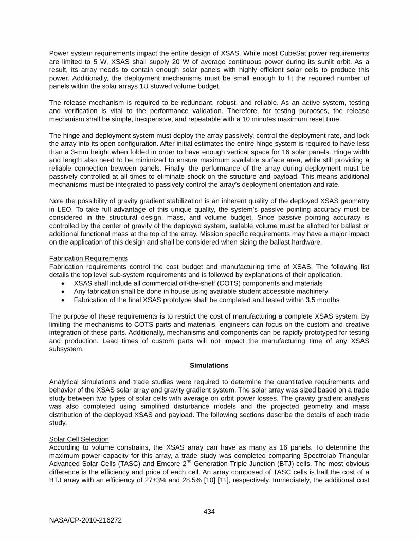
may outweigh the inconsistency in the efficiency of the TASC cells. The primary components of the trade study are included in Table 2 for average Low Earth Orbit (LEO) conditions. All specific values for the BTJ and TASC cell properties were collected from references [10] and [11] at max power (Vmp × Imp) conditions. With solar arrays on each side of the deployed array, power can be collected throughout the entire sunlit orbit. However, because of the nadir orientation of the array, its solar incidence and therefore cell efficiency constantly change according to the cosine of the incidence angle. As a result, the primary power loss to the array is estimated by the average incidence angle over the sunlit orbit, or 43° at a 1000-km orbit. Based on these results it is obvious the BTJ cells, with an average power of 23.1 W (nearly 5 times traditional CubeSat solar arrays), are the better choice.
Table 2. Beginning of Life Solar Cell Trade Study for 1000-km LEO Orbit
BTJ TASC Parameter Value Value Units
Layout
Solar Cell Area 32.86 2.28 cm2 Solar Cells Per String 2 6 Parallel Strings (Facet) 1 4 Number of Panels 16 16
Power
Cell Efficiency at Reference Temperature 28.5 27.0 % Reference Temperature 28.0 25.0 °C Maximum Power 32.8 23.6 W Temperature Loss Coefficient -0.006 -0.021 %/°C Temperature Power Loss at 67°C† -2.5 -12.7 % Incidence Angle Power Loss at 43 Deg ‡ -26.8 -26.8 %
Net Max Power 32.0 20.6 W Net Average Power 23.1 14.3 W
Attitude Control System Beyond its obvious capabilities as a power generation tool, the XSAS system can provide enhancements to the CubeSat attitude control system by its very nature. By elongating the CubeSat along a single axis, the CubeSat will naturally begin to orient itself with its long axis perpendicular to the instantaneous tangent plane to the Earth underneath it. We can explore the relationship between length and this orientation tendency through equation 1:
3 , (1)
where is gravity gradient torque, is the Earth’s gravitational parameter, is the orbital radius, is the zenith vector in body coordinates, and is the diagonal inertial matrix in the body frame. This restoring torque causes the vehicle to return to a nadir pointing position should any disturbances occur (such as orbital motion, radiation pressure or magnetic torquing). It can easily be seen from the equations that no torque exists if the body is oriented nadir. If the body is tilted, however, and then the nadir position will be a stable equilibrium, and the vehicle will return to a nadir pointing position passively. A complete design of XSAS must ensure that this restoring torque is greater than any of the lesser disturbances to assure pointing accuracy and mission success. Specifically in the case of the large flat shape of the solar array on XSAS, the torque caused by aerodynamic and solar radiation drag in LEO must be examined with the following equations:
† Temperature of a typical flat solar panel in LEO [9] ‡ Cosine (average array solar incidence angle)
NASA/CP-2010-216272
436
1 cos , (2)
where is the solar radiation pressure torque, is the solar constant, c is the speed of light, is the surface area, is the reflectance factor, is the solar incidence angle, is the center of solar pressure, and is the center of gravity; and
, (3)
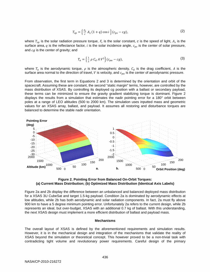
where is the aerodynamic torque, is the atmospheric density, is the drag coefficient, is the surface area normal to the direction of travel, is velocity, and is the center of aerodynamic pressure. From observation, the first term in Equations 2 and 3 is determined by the orientation and orbit of the spacecraft. Assuming these are constant, the second “static margin” terms, however, are controlled by the mass distribution of XSAS. By controlling its deployed cg position with a ballast or secondary payload, these terms can be minimized to ensure the gravity gradient stabilizing torque is dominant. Figure 2 displays the results from a simulation that estimates the nadir pointing error for a 180° orbit between poles at a range of LEO altitudes (500 to 2000 km). The simulation uses inputted mass and geometric values for an XSAS array, ballast, and payload. It assumes all restoring and disturbance torques are balanced to determine the stable nadir orientation.
Figure 2. Pointing Error from Balanced On-Orbit Torques: (a) Current Mass Distribution; (b) Optimized Mass Distribution (Identical Axis Labels)
Figure 2a and 2b display the difference between an unbalanced and balanced deployed mass distribution for a XSAS 3U CubeSat and target 1.5-kg payload. Condition 2a is dominated by aerodynamic effects at low altitudes, while 2b has both aerodynamic and solar radiation components. In fact, 2a must fly above 900 km to have a 5 degree minimum pointing error. Unfortunately 2a refers to the current design, while 2b represents an ideal, but over-budget, XSAS with an additional 0.7 kg of ballast. With this understanding, the next XSAS design must implement a more efficient distribution of ballast and payload mass.
Mechanisms The overall layout of XSAS is defined by the aforementioned requirements and simulation results. However, it is in the mechanical design and integration of the mechanisms that validate the reality of XSAS beyond the simulation or theoretical concept. This however proved to be a non-trivial task with contradicting tight volume and revolutionary power requirements. Careful design of the primary
050
100150
200
5001000
15002000
-30-25-20-15-10-505
050
100150
200
5001000
15002000
-2-1.5
-1-0.5
00.5
1
Altitude (km) Orbit Position (deg)
Pointing Error (deg)
a. b.
NASA/CP-2010-216272
437
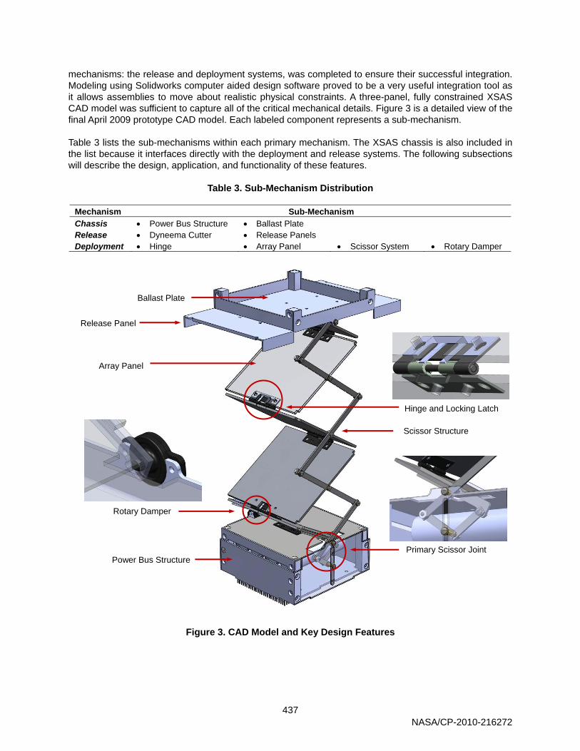
mechanisms: the release and deployment systems, was completed to ensure their successful integration. Modeling using Solidworks computer aided design software proved to be a very useful integration tool as it allows assemblies to move about realistic physical constraints. A three-panel, fully constrained XSAS CAD model was sufficient to capture all of the critical mechanical details. Figure 3 is a detailed view of the final April 2009 prototype CAD model. Each labeled component represents a sub-mechanism. Table 3 lists the sub-mechanisms within each primary mechanism. The XSAS chassis is also included in the list because it interfaces directly with the deployment and release systems. The following subsections will describe the design, application, and functionality of these features.
Table 3. Sub-Mechanism Distribution
Mechanism Sub-Mechanism Chassis • Power Bus Structure • Ballast Plate Release • Dyneema Cutter • Release Panels Deployment • Hinge • Array Panel • Scissor System • Rotary Damper
Figure 3. CAD Model and Key Design Features
Ballast Plate
Release Panel
Scissor Structure
Array Panel
Rotary Damper
Power Bus Structure Primary Scissor Joint
Hinge and Locking Latch
NASA/CP-2010-216272
438
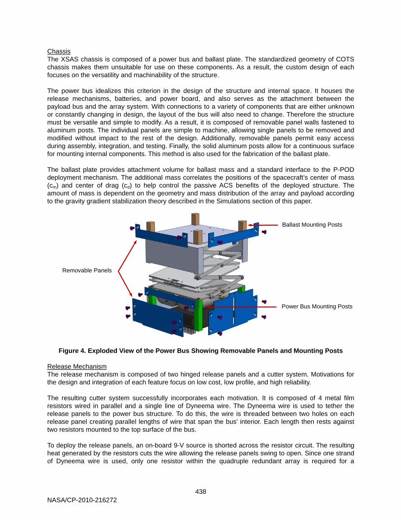
Chassis The XSAS chassis is composed of a power bus and ballast plate. The standardized geometry of COTS chassis makes them unsuitable for use on these components. As a result, the custom design of each focuses on the versatility and machinability of the structure. The power bus idealizes this criterion in the design of the structure and internal space. It houses the release mechanisms, batteries, and power board, and also serves as the attachment between the payload bus and the array system. With connections to a variety of components that are either unknown or constantly changing in design, the layout of the bus will also need to change. Therefore the structure must be versatile and simple to modify. As a result, it is composed of removable panel walls fastened to aluminum posts. The individual panels are simple to machine, allowing single panels to be removed and modified without impact to the rest of the design. Additionally, removable panels permit easy access during assembly, integration, and testing. Finally, the solid aluminum posts allow for a continuous surface for mounting internal components. This method is also used for the fabrication of the ballast plate. The ballast plate provides attachment volume for ballast mass and a standard interface to the P-POD deployment mechanism. The additional mass correlates the positions of the spacecraft’s center of mass (cm) and center of drag (cd) to help control the passive ACS benefits of the deployed structure. The amount of mass is dependent on the geometry and mass distribution of the array and payload according to the gravity gradient stabilization theory described in the Simulations section of this paper.
Figure 4. Exploded View of the Power Bus Showing Removable Panels and Mounting Posts Release Mechanism The release mechanism is composed of two hinged release panels and a cutter system. Motivations for the design and integration of each feature focus on low cost, low profile, and high reliability. The resulting cutter system successfully incorporates each motivation. It is composed of 4 metal film resistors wired in parallel and a single line of Dyneema wire. The Dyneema wire is used to tether the release panels to the power bus structure. To do this, the wire is threaded between two holes on each release panel creating parallel lengths of wire that span the bus' interior. Each length then rests against two resistors mounted to the top surface of the bus. To deploy the release panels, an on-board 9-V source is shorted across the resistor circuit. The resulting heat generated by the resistors cuts the wire allowing the release panels swing to open. Since one strand of Dyneema wire is used, only one resistor within the quadruple redundant array is required for a
Removable Panels
Ballast Mounting Posts
Power Bus Mounting Posts
NASA/CP-2010-216272
439
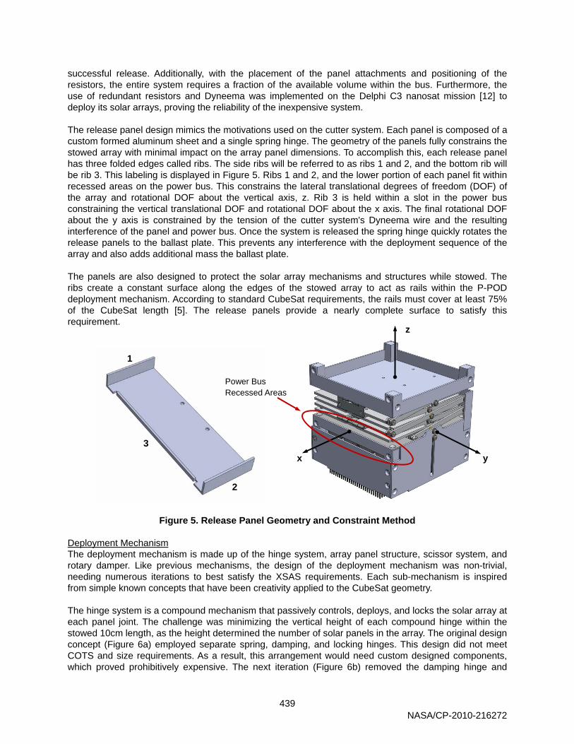
successful release. Additionally, with the placement of the panel attachments and positioning of the resistors, the entire system requires a fraction of the available volume within the bus. Furthermore, the use of redundant resistors and Dyneema was implemented on the Delphi C3 nanosat mission [12] to deploy its solar arrays, proving the reliability of the inexpensive system. The release panel design mimics the motivations used on the cutter system. Each panel is composed of a custom formed aluminum sheet and a single spring hinge. The geometry of the panels fully constrains the stowed array with minimal impact on the array panel dimensions. To accomplish this, each release panel has three folded edges called ribs. The side ribs will be referred to as ribs 1 and 2, and the bottom rib will be rib 3. This labeling is displayed in Figure 5. Ribs 1 and 2, and the lower portion of each panel fit within recessed areas on the power bus. This constrains the lateral translational degrees of freedom (DOF) of the array and rotational DOF about the vertical axis, z. Rib 3 is held within a slot in the power bus constraining the vertical translational DOF and rotational DOF about the x axis. The final rotational DOF about the y axis is constrained by the tension of the cutter system's Dyneema wire and the resulting interference of the panel and power bus. Once the system is released the spring hinge quickly rotates the release panels to the ballast plate. This prevents any interference with the deployment sequence of the array and also adds additional mass the ballast plate. The panels are also designed to protect the solar array mechanisms and structures while stowed. The ribs create a constant surface along the edges of the stowed array to act as rails within the P-POD deployment mechanism. According to standard CubeSat requirements, the rails must cover at least 75% of the CubeSat length [5]. The release panels provide a nearly complete surface to satisfy this requirement.
Figure 5. Release Panel Geometry and Constraint Method Deployment Mechanism The deployment mechanism is made up of the hinge system, array panel structure, scissor system, and rotary damper. Like previous mechanisms, the design of the deployment mechanism was non-trivial, needing numerous iterations to best satisfy the XSAS requirements. Each sub-mechanism is inspired from simple known concepts that have been creativity applied to the CubeSat geometry. The hinge system is a compound mechanism that passively controls, deploys, and locks the solar array at each panel joint. The challenge was minimizing the vertical height of each compound hinge within the stowed 10cm length, as the height determined the number of solar panels in the array. The original design concept (Figure 6a) employed separate spring, damping, and locking hinges. This design did not meet COTS and size requirements. As a result, this arrangement would need custom designed components, which proved prohibitively expensive. The next iteration (Figure 6b) removed the damping hinge and
z
y x
1
2
3
Power Bus Recessed Areas
NASA/CP-2010-216272
440
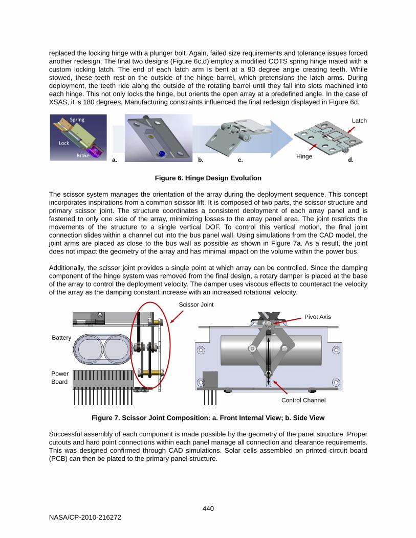
replaced the locking hinge with a plunger bolt. Again, failed size requirements and tolerance issues forced another redesign. The final two designs (Figure 6c,d) employ a modified COTS spring hinge mated with a custom locking latch. The end of each latch arm is bent at a 90 degree angle creating teeth. While stowed, these teeth rest on the outside of the hinge barrel, which pretensions the latch arms. During deployment, the teeth ride along the outside of the rotating barrel until they fall into slots machined into each hinge. This not only locks the hinge, but orients the open array at a predefined angle. In the case of XSAS, it is 180 degrees. Manufacturing constraints influenced the final redesign displayed in Figure 6d.
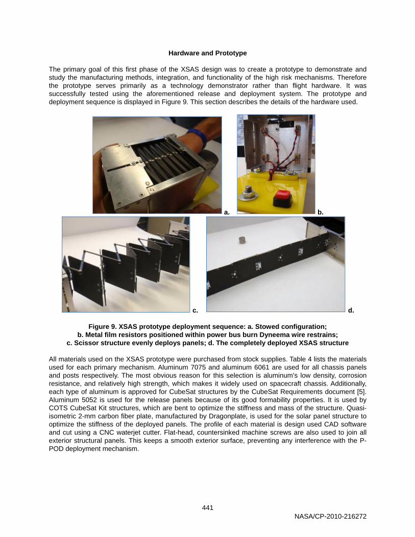
Figure 6. Hinge Design Evolution The scissor system manages the orientation of the array during the deployment sequence. This concept incorporates inspirations from a common scissor lift. It is composed of two parts, the scissor structure and primary scissor joint. The structure coordinates a consistent deployment of each array panel and is fastened to only one side of the array, minimizing losses to the array panel area. The joint restricts the movements of the structure to a single vertical DOF. To control this vertical motion, the final joint connection slides within a channel cut into the bus panel wall. Using simulations from the CAD model, the joint arms are placed as close to the bus wall as possible as shown in Figure 7a. As a result, the joint does not impact the geometry of the array and has minimal impact on the volume within the power bus. Additionally, the scissor joint provides a single point at which array can be controlled. Since the damping component of the hinge system was removed from the final design, a rotary damper is placed at the base of the array to control the deployment velocity. The damper uses viscous effects to counteract the velocity of the array as the damping constant increase with an increased rotational velocity.
Figure 7. Scissor Joint Composition: a. Front Internal View; b. Side View Successful assembly of each component is made possible by the geometry of the panel structure. Proper cutouts and hard point connections within each panel manage all connection and clearance requirements. This was designed confirmed through CAD simulations. Solar cells assembled on printed circuit board (PCB) can then be plated to the primary panel structure.
a. b. c. d.
Scissor Joint
Battery
Power Board
Control Channel
Pivot Axis
Latch
Hinge
NASA/CP-2010-216272
441
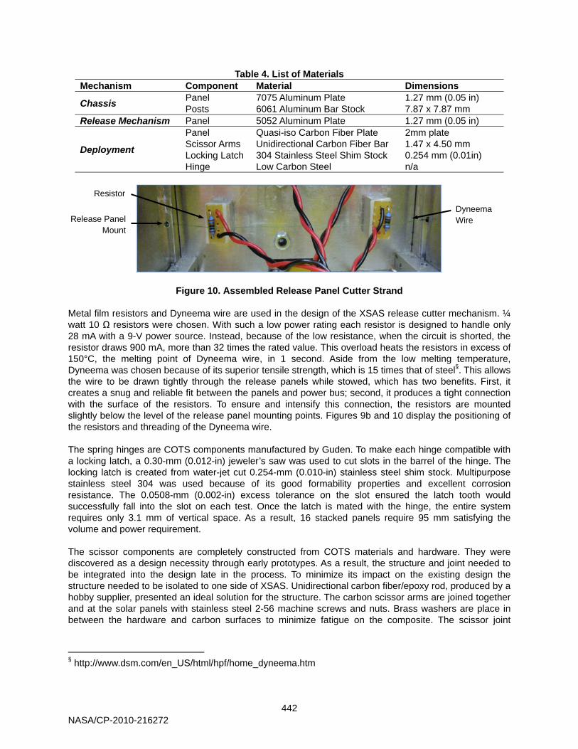
Hardware and Prototype The primary goal of this first phase of the XSAS design was to create a prototype to demonstrate and study the manufacturing methods, integration, and functionality of the high risk mechanisms. Therefore the prototype serves primarily as a technology demonstrator rather than flight hardware. It was successfully tested using the aforementioned release and deployment system. The prototype and deployment sequence is displayed in Figure 9. This section describes the details of the hardware used.
a. b.
c. d.
Figure 9. XSAS prototype deployment sequence: a. Stowed configuration; b. Metal film resistors positioned within power bus burn Dyneema wire restrains;
c. Scissor structure evenly deploys panels; d. The completely deployed XSAS structure All materials used on the XSAS prototype were purchased from stock supplies. Table 4 lists the materials used for each primary mechanism. Aluminum 7075 and aluminum 6061 are used for all chassis panels and posts respectively. The most obvious reason for this selection is aluminum’s low density, corrosion resistance, and relatively high strength, which makes it widely used on spacecraft chassis. Additionally, each type of aluminum is approved for CubeSat structures by the CubeSat Requirements document [5]. Aluminum 5052 is used for the release panels because of its good formability properties. It is used by COTS CubeSat Kit structures, which are bent to optimize the stiffness and mass of the structure. Quasi-isometric 2-mm carbon fiber plate, manufactured by Dragonplate, is used for the solar panel structure to optimize the stiffness of the deployed panels. The profile of each material is design used CAD software and cut using a CNC waterjet cutter. Flat-head, countersinked machine screws are also used to join all exterior structural panels. This keeps a smooth exterior surface, preventing any interference with the P-POD deployment mechanism.
NASA/CP-2010-216272
442
Table 4. List of Materials Mechanism Component Material Dimensions
Chassis Panel 7075 Aluminum Plate 1.27 mm (0.05 in) Posts 6061 Aluminum Bar Stock 7.87 x 7.87 mm
Release Mechanism Panel 5052 Aluminum Plate 1.27 mm (0.05 in)
Deployment
Panel Quasi-iso Carbon Fiber Plate 2mm plate Scissor Arms Unidirectional Carbon Fiber Bar 1.47 x 4.50 mm Locking Latch 304 Stainless Steel Shim Stock 0.254 mm (0.01in) Hinge Low Carbon Steel n/a
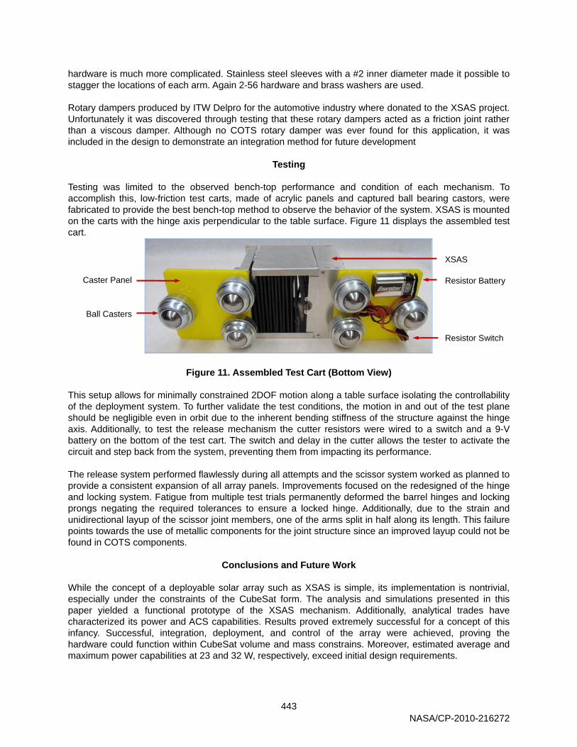
Figure 10. Assembled Release Panel Cutter Strand Metal film resistors and Dyneema wire are used in the design of the XSAS release cutter mechanism. ¼ watt 10 Ω resistors were chosen. With such a low power rating each resistor is designed to handle only 28 mA with a 9-V power source. Instead, because of the low resistance, when the circuit is shorted, the resistor draws 900 mA, more than 32 times the rated value. This overload heats the resistors in excess of 150°C, the melting point of Dyneema wire, in 1 second. Aside from the low melting temperature, Dyneema was chosen because of its superior tensile strength, which is 15 times that of steel§. This allows the wire to be drawn tightly through the release panels while stowed, which has two benefits. First, it creates a snug and reliable fit between the panels and power bus; second, it produces a tight connection with the surface of the resistors. To ensure and intensify this connection, the resistors are mounted slightly below the level of the release panel mounting points. Figures 9b and 10 display the positioning of the resistors and threading of the Dyneema wire.
The spring hinges are COTS components manufactured by Guden. To make each hinge compatible with a locking latch, a 0.30-mm (0.012-in) jeweler’s saw was used to cut slots in the barrel of the hinge. The locking latch is created from water-jet cut 0.254-mm (0.010-in) stainless steel shim stock. Multipurpose stainless steel 304 was used because of its good formability properties and excellent corrosion resistance. The 0.0508-mm (0.002-in) excess tolerance on the slot ensured the latch tooth would successfully fall into the slot on each test. Once the latch is mated with the hinge, the entire system requires only 3.1 mm of vertical space. As a result, 16 stacked panels require 95 mm satisfying the volume and power requirement. The scissor components are completely constructed from COTS materials and hardware. They were discovered as a design necessity through early prototypes. As a result, the structure and joint needed to be integrated into the design late in the process. To minimize its impact on the existing design the structure needed to be isolated to one side of XSAS. Unidirectional carbon fiber/epoxy rod, produced by a hobby supplier, presented an ideal solution for the structure. The carbon scissor arms are joined together and at the solar panels with stainless steel 2-56 machine screws and nuts. Brass washers are place in between the hardware and carbon surfaces to minimize fatigue on the composite. The scissor joint
§ http://www.dsm.com/en_US/html/hpf/home_dyneema.htm
Dyneema Wire Release Panel
Mount
Resistor
NASA/CP-2010-216272
443
hardware is much more complicated. Stainless steel sleeves with a #2 inner diameter made it possible to stagger the locations of each arm. Again 2-56 hardware and brass washers are used. Rotary dampers produced by ITW Delpro for the automotive industry where donated to the XSAS project. Unfortunately it was discovered through testing that these rotary dampers acted as a friction joint rather than a viscous damper. Although no COTS rotary damper was ever found for this application, it was included in the design to demonstrate an integration method for future development
Testing Testing was limited to the observed bench-top performance and condition of each mechanism. To accomplish this, low-friction test carts, made of acrylic panels and captured ball bearing castors, were fabricated to provide the best bench-top method to observe the behavior of the system. XSAS is mounted on the carts with the hinge axis perpendicular to the table surface. Figure 11 displays the assembled test cart.
Figure 11. Assembled Test Cart (Bottom View)
This setup allows for minimally constrained 2DOF motion along a table surface isolating the controllability of the deployment system. To further validate the test conditions, the motion in and out of the test plane should be negligible even in orbit due to the inherent bending stiffness of the structure against the hinge axis. Additionally, to test the release mechanism the cutter resistors were wired to a switch and a 9-V battery on the bottom of the test cart. The switch and delay in the cutter allows the tester to activate the circuit and step back from the system, preventing them from impacting its performance. The release system performed flawlessly during all attempts and the scissor system worked as planned to provide a consistent expansion of all array panels. Improvements focused on the redesigned of the hinge and locking system. Fatigue from multiple test trials permanently deformed the barrel hinges and locking prongs negating the required tolerances to ensure a locked hinge. Additionally, due to the strain and unidirectional layup of the scissor joint members, one of the arms split in half along its length. This failure points towards the use of metallic components for the joint structure since an improved layup could not be found in COTS components.
Conclusions and Future Work While the concept of a deployable solar array such as XSAS is simple, its implementation is nontrivial, especially under the constraints of the CubeSat form. The analysis and simulations presented in this paper yielded a functional prototype of the XSAS mechanism. Additionally, analytical trades have characterized its power and ACS capabilities. Results proved extremely successful for a concept of this infancy. Successful, integration, deployment, and control of the array were achieved, proving the hardware could function within CubeSat volume and mass constrains. Moreover, estimated average and maximum power capabilities at 23 and 32 W, respectively, exceed initial design requirements.
XSAS
Ball Casters
Caster Panel Resistor Battery
Resistor Switch
NASA/CP-2010-216272
444
As expected of a technology demonstrator for a new and novel design, the simulation and test results also revealed many improvements that can be made to the current system. Areas of focus address improvements to current hardware such as fatigue, tolerance, and thermal concerns with the hinge and locking mechanism, identification and integration of a damping mechanism, and improved gravity gradient capabilities with a more efficient mass distribution and payload interface. Additionally, new challenges such as the solar panel electrical integration, cross-panel wiring harness design, improved array orientation and structural analysis, and an understanding of the unconstrained release and deployment dynamics, will bring XSAS closer to flight hardware status. The University of Michigan Student Space Systems Fabrication Laboratory (S3FL), an active student group, has taken on the XSAS concept for continued development. S3FL will focus on improved design and analysis of the mechanisms, structural mechanics, and deployment dynamics of a new XSAS prototype. This summer they will test the prototype in microgravity within NASA’s Reduced Gravity Student Opportunities Program. This program allows selected teams to fly onboard the famed “Vomit Comet” to perform experiments in a controlled and unconstrained 6-DOF environment. This first microgravity flight will help in the dynamic analysis of the XSAS system and prepare for additional, future flights, supporting CubeSats in low Earth orbit.
Acknowledgements The authors would like to thank the students of AE/AOSS 582 and 583 during the Fall 2008 and Winter 2009 school year for their dedicated efforts in supporting the XSAS project. In particular, Eric Kosmyna made significant contributions to XSAS’ development. Furthermore, the authors are grateful to the S3FL and XSAS Reduced Gravity Student Opportunities Program teams for continuing development and flying it onboard the “Vomit Comet”.
References
1. Berry, LB and Brown, WD and Dawson, WP and Suenaga, EL and CA, H.A.C.O.E.L.S. and others,
“Flexible Integrated Solar Cell Array”, AFAPL-TR-67-100, Contract AF 33-(615)-2750, Aug. 1967, Space Systems Div., Hughes Aircraft Co, 1967.
2. ____, “Deployable Solar Array”, US Patent 3,532,299, 1970. 3. Aguirre-Martinez, M. “Developments in deployable masts to support flexible solar arrays”, CSA
Illumina, p391-398, 1984. 4. Malone, P.K. and Williams, G.T., “inflatable solar array”, Journal of Propulsion and Power, v12, n5,
p866-872, 1996. 5. ____, “CubeSat Specifications”, Available at: www.cubesat.org, 2009. 6. Rossberg, F., “Structural Design of a NPS CubeSat Launcher”, Storming Media, 2008. 7. Koyama, M. and Suzuki, K. and Imamura, O. and Yamada, K., “Study on Mini Re-Entry System Using
Deployable Membrane Aeroshell”, Transactions of Space Technology Japan, v7, 2009. 8. Pearson, J. and Levin, E. and Oldson, J. and Carroll, J., “ElectroDynamic Delivery Experiment
(EDDE)”, AIP Conference Proceedings, p425-432, 2001. 9. Larson, W., Wertz, J., “Space Mission Analysis and Design”, Microcosm Press, 1999. 10. ____, “Triple-Junction with Monolithic Diode (BTJM) High Efficiency Solar Cells for Space
Applications”, Emcore, Inc, Available at: http://www.emcore.com/assets/photovoltaics/Emcore+BTJM+Solar+Cell+Data+Sheet_May-07.pdf, 2010.
11. ____, “Triangular Advanced Solar Cells”, Spectrolab, Available at: http://www.spectrolab.com/DataSheets/PV/PV_NM_TASC_ITJ.pdf, 2010.
12. ____. “Delphi C-3” TU Delft, Available at: http://www.delfic3.nl/, 2010.
NASA/CP-2010-216272


![Senatore Alessandria.ppt [Sola lettura]cardioalessandria.it/w/wp-content/themes/seos... · Chiusura dell’auricola sinistra: Pro Gaetano Senatore ... per chiusura percutanea/escissione](https://img.pdfslide.net/doc/110x75/6010b60a9d3f1e47c45ef6a7/senatore-sola-letturacardioalessandriaitwwp-contentthemesseos-chiusura.jpg)