Embed Size (px)
Citation preview

Concepts of Multimedia Concepts of Multimedia Processing and TransmissionProcessing and Transmission
IT 481, Lecture #7Dennis McCaughey, Ph.D.
19 March, 2007
08/28/2006IT 481, Fall 20062
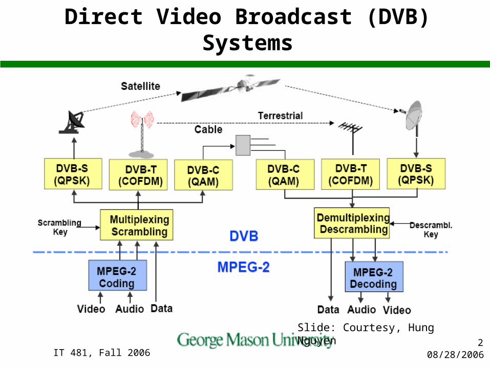
Direct Video Broadcast (DVB) Systems
Slide: Courtesy, Hung Nguyen

08/28/2006IT 481, Fall 20063
Processing of The Streams in The Set-Top Box (STB)
Slide: Courtesy, Hung Nguyen

08/28/2006IT 481, Fall 20064
Multimedia CommunicationsMultimedia CommunicationsStandards and ApplicationsStandards and Applications
Slide: Courtesy, Hung Nguyen

08/28/2006IT 481, Fall 20065
Video Coding StandardsVideo Coding Standards
ITU H.261 for Video Teleconference (VTC) ITU H.263 for VTC over POTS ITU H.262 for VTC over ATM/broadband and digital TV
networks ISO MPEG-1 for movies on CDROM (VCD)
– 1.2 Mbps for video coding and 256 Kbps for audio coding ISO MPEG-2 for broadcast quality video on DVD
– 2-15 Mbps allocated for audio and video coding Low-bit rate telephony over POTS
– 10 Kbps for video and 5.3 Kbps for audio Internet and mobile communication: MPEG-4
– Very Low Bit Rate (VLBR) code to be compatible with H.263 Multimedia content description interface MPEG-7
– Description schemes and description definition language for integrated multimedia search engine
Slide: Courtesy, Hung Nguyen
08/28/2006IT 481, Fall 20066
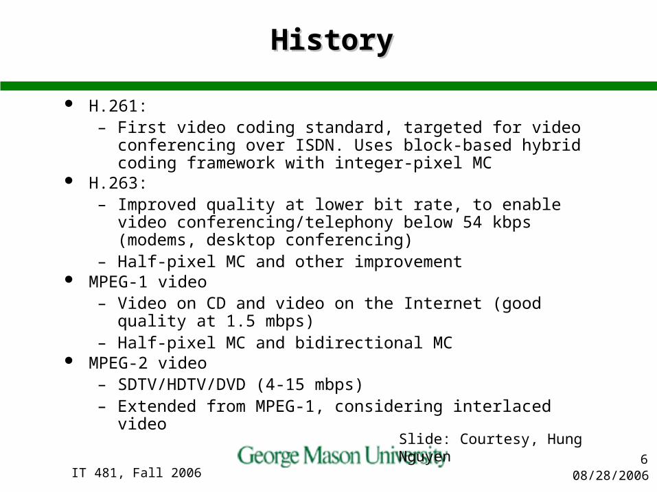
HistoryHistory
H.261:– First video coding standard, targeted for video conferencing over
ISDN. Uses block-based hybrid coding framework with integer-pixel MC
H.263:– Improved quality at lower bit rate, to enable video
conferencing/telephony below 54 kbps (modems, desktop conferencing)
– Half-pixel MC and other improvement MPEG-1 video
– Video on CD and video on the Internet (good quality at 1.5 mbps)– Half-pixel MC and bidirectional MC
MPEG-2 video– SDTV/HDTV/DVD (4-15 mbps)– Extended from MPEG-1, considering interlaced video
Slide: Courtesy, Hung Nguyen
08/28/2006IT 481, Fall 20067
H.261 Video Coding StandardH.261 Video Coding Standard
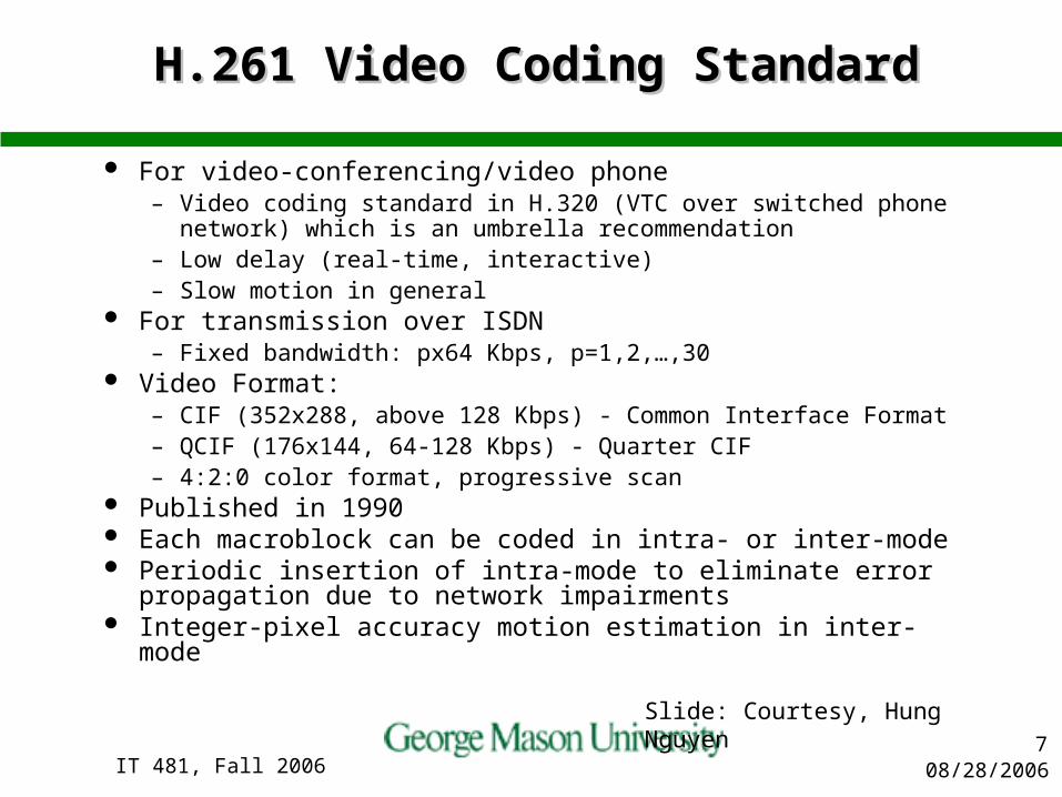
For video-conferencing/video phone– Video coding standard in H.320 (VTC over switched phone
network) which is an umbrella recommendation– Low delay (real-time, interactive)– Slow motion in general
For transmission over ISDN– Fixed bandwidth: px64 Kbps, p=1,2,…,30
Video Format:– CIF (352x288, above 128 Kbps) - Common Interface Format– QCIF (176x144, 64-128 Kbps) - Quarter CIF – 4:2:0 color format, progressive scan
Published in 1990 Each macroblock can be coded in intra- or inter-mode Periodic insertion of intra-mode to eliminate error propagation
due to network impairments Integer-pixel accuracy motion estimation in inter-mode
Slide: Courtesy, Hung Nguyen
08/28/2006IT 481, Fall 20068
H.261 EncoderH.261 Encoder
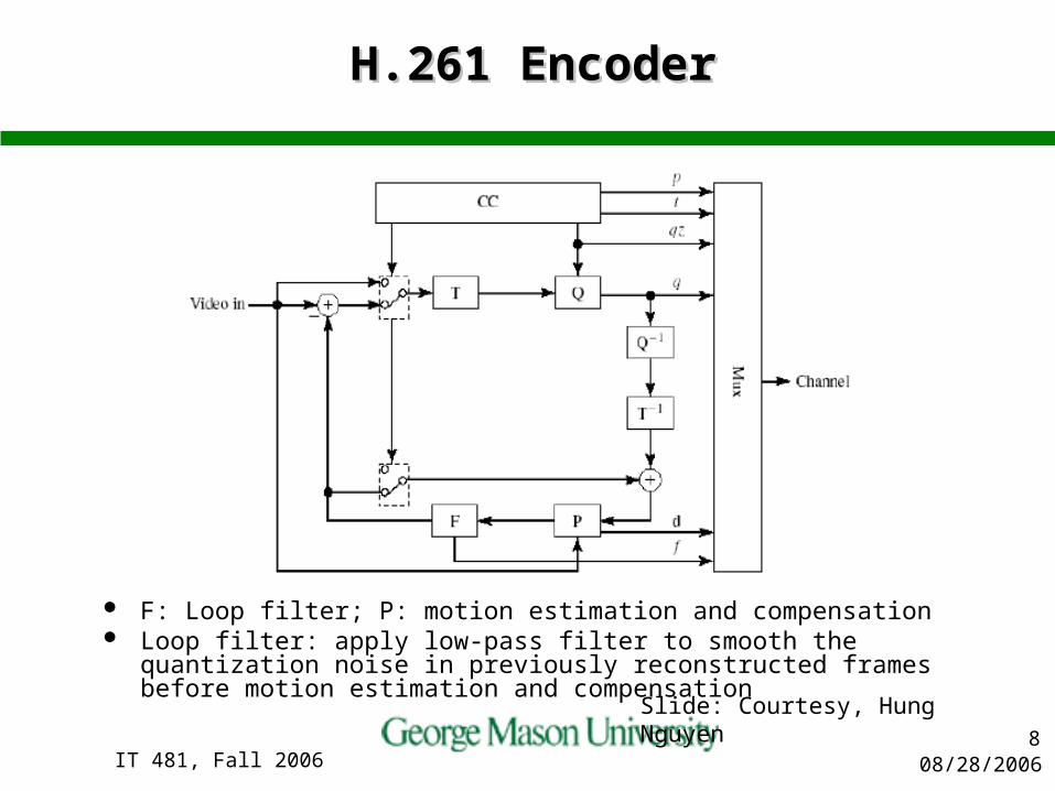
F: Loop filter; P: motion estimation and compensation Loop filter: apply low-pass filter to smooth the quantization noise in
previously reconstructed frames before motion estimation and compensation Slide: Courtesy, Hung Nguyen

08/28/2006IT 481, Fall 20069
Picture Frames - OverviewPicture Frames - Overview
Three frame types: I-Picture (Intra-frame picture), P-Picture (Inter-frame predicted picture) and B-Picture (Bi-directional predicted- interpolated pictures)
I-Picture is being coded by intra-frame coding. When encoding I-Picture, we only reduce the spatial redundancy in the picture without referencing other pictures. The coding process is much similar to JPEG Standard. So encoding I-Picture is less complex than P-frame and B-frame
The basic coding unit is a 8 by 8 matrix block. A macroblock is consists of six block: 4 block of luminance (Y) , one block of Cb chrominance, and one block of Cr chrominance
Slide: Courtesy, Hung Nguyen

08/28/2006IT 481, Fall 200610
Frame TypesFrame Types
Intracoded Frames -> I-Frames– Level of compression is relatively small 10:1 to 20:1– Present at regular intervals to limit extent of errors– Number of frames between I-frames is known as the Group of
pictures (GOP)– 10:1 to 20:1 compression ratio
Intercoded Frames– Predicted Frames-> P-Frames
Significant compression level achieved here Errors are propagated 20:1 to 30:1 compression ratio
– Bidirectional Frames -> B-Frames Highest levels of compression achieved B-frames are not used for prediction, thus errors are not
propagated 30:1 to 50:1 compression ratio

08/28/2006IT 481, Fall 200611
Macro Blocks & Color Sub-sampling Schemes
A macroblock consists of 4 8x8 pixel blocks
Slide: Courtesy, Hung Nguyen

08/28/2006IT 481, Fall 200612
Sub-sampling of Chrominance Sub-sampling of Chrominance InformationInformation
Transforming (R,G,B)->(Y,Cb,Cr) provides two advantages:
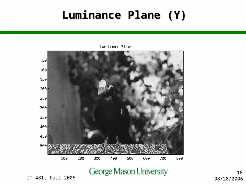
1)The human visual system (HVS) is more sensitive to Y component than the Cb or Cr components.
2) Cb and Cr are far less correlated with Y than R with G, R with Blue and Blue with G, thus reducing TV transmission bandwidths.
Cb and Cr both require far less bandwidth and can be sampled more coarsely (Shannon).
By doing so we can reduce data without affecting visual quality from a personal view. Slide: Courtesy, Hung Nguyen

08/28/2006IT 481, Fall 200613
Color Space ConversionColor Space Conversion
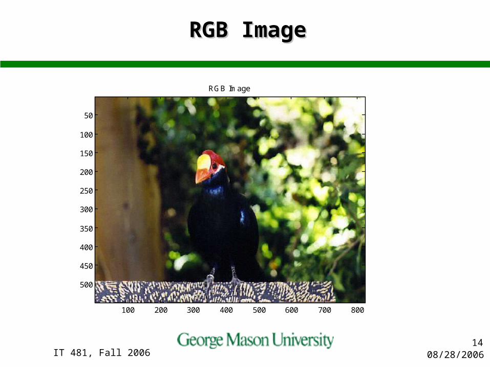
In general , each pixel in a picture consists of three components : R (Red), G (Green), B (Blue). (R,G,B) must be converted to (Y,Cb,Cr) in MPEG-1 before processing
We can view the color value of each pixel from RGB color space , or YCbCr color space
Because (Y,Cb,Cr) is less correlated than (R,G,B), coding using (Y,Cb,Cr) components is more efficient.
(Y,U,V) can also be used to denote (Y,Cb,Cr), however it most appropriately represents the analog TV equivalent
Slide: Courtesy, Hung Nguyen
08/28/2006IT 481, Fall 200614
RGB ImageRGB Image
RGB Image
100 200 300 400 500 600 700 800
50
100
150
200
250
300
350
400
450
500

08/28/2006IT 481, Fall 200615
Compressed Image (QSF=24)Compressed Image (QSF=24)
Compressed Image
100 200 300 400 500 600 700 800
50
100
150
200
250
300
350
400
450
500
08/28/2006IT 481, Fall 200616
Luminance Plane (Y)Luminance Plane (Y)
Luminance Plane
100 200 300 400 500 600 700 800
50
100
150
200
250
300
350
400
450
500

08/28/2006IT 481, Fall 200617
Blue Chrominance Plane (Cb)Blue Chrominance Plane (Cb)
Blue Chrominance Plane
100 200 300 400 500 600 700 800
50
100
150
200
250
300
350
400
450
500

08/28/2006IT 481, Fall 200618
Red Chrominance Plane (Cr)Red Chrominance Plane (Cr)
Red Chrominance Plane
100 200 300 400 500 600 700 800
50
100
150
200
250
300
350
400
450
500
08/28/2006IT 481, Fall 200619
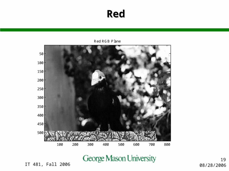
RedRed
Red RGB Plane
100 200 300 400 500 600 700 800
50
100
150
200
250
300
350
400
450
500
08/28/2006IT 481, Fall 200620
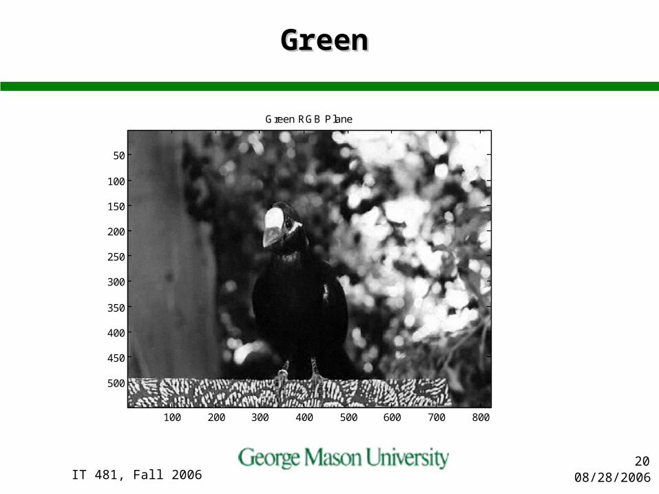
Green Green
Green RGB Plane
100 200 300 400 500 600 700 800
50
100
150
200
250
300
350
400
450
500

08/28/2006IT 481, Fall 200621
BlueBlue
Blue RGB Plane
100 200 300 400 500 600 700 800
50
100
150
200
250
300
350
400
450
500
08/28/2006IT 481, Fall 200622
DCT (discrete cosine transform)DCT (discrete cosine transform)
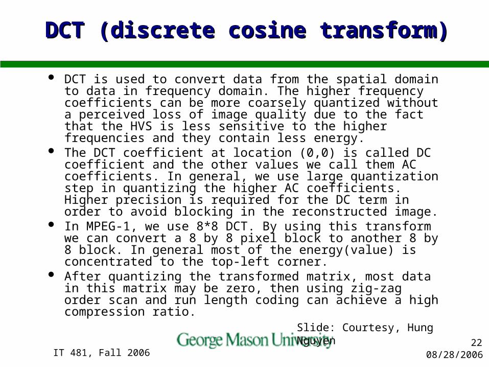
DCT is used to convert data from the spatial domain to data in frequency domain. The higher frequency coefficients can be more coarsely quantized without a perceived loss of image quality due to the fact that the HVS is less sensitive to the higher frequencies and they contain less energy.
The DCT coefficient at location (0,0) is called DC coefficient and the other values we call them AC coefficients. In general, we use large quantization step in quantizing the higher AC coefficients. Higher precision is required for the DC term in order to avoid blocking in the reconstructed image.
In MPEG-1, we use 8*8 DCT. By using this transform we can convert a 8 by 8 pixel block to another 8 by 8 block. In general most of the energy(value) is concentrated to the top-left corner.
After quantizing the transformed matrix, most data in this matrix may be zero, then using zig-zag order scan and run length coding can achieve a high compression ratio. Slide: Courtesy, Hung Nguyen
08/28/2006IT 481, Fall 200623
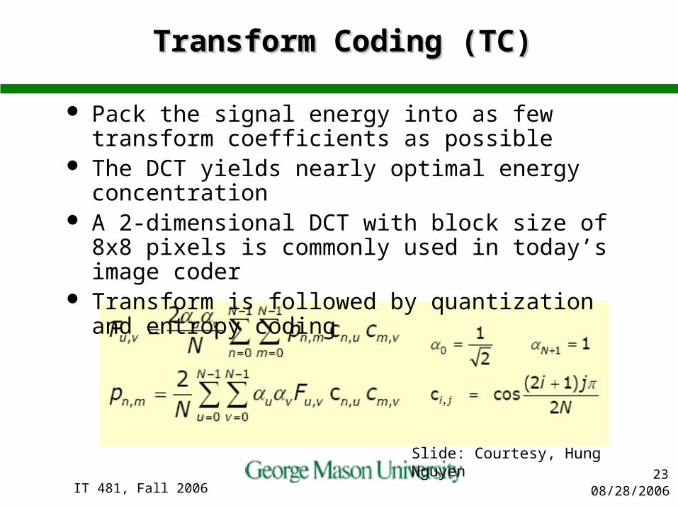
Transform Coding (TC)Transform Coding (TC)
Pack the signal energy into as few transform coefficients as possible
The DCT yields nearly optimal energy concentration A 2-dimensional DCT with block size of 8x8 pixels is
commonly used in today’s image coder Transform is followed by quantization and entropy
coding
Slide: Courtesy, Hung Nguyen

08/28/2006IT 481, Fall 200624
2D DCT and IDCT2D DCT and IDCT
u, v, x, y = 0, 1,2, ….,7
Slide: Courtesy, Hung Nguyen

08/28/2006IT 481, Fall 200625
DCT Scan ModesDCT Scan Modes
The zigzag scan used in MPEG-1 is suitable for progressive images where frequency components have equal importance in each horizontal and vertical direction. (Frame pictures only)
In MPEG-2, an alternate scan is introduced because interlaced images tend to have higher frequency components in the vertical direction. Thus, the scanning order weighs more on the higher vertical frequencies than the same horizontal frequencies. Selection between these two zigzag scan orders can be made on a picture basis. (Frame and field pictures allowed)
Slide: Courtesy, Hung Nguyen

08/28/2006IT 481, Fall 200626
Motion Compensation
Try to match each block in the actual picture to content in the previous picture. Matching is made by shifting each of the 8 x 8 blocks of the two successive pictures pixel by pixel each direction -> Motion vector
Subtract the two blocks -> Difference block Transmit the motion vector and the difference block
Slide: Courtesy, Hung Nguyen
08/28/2006IT 481, Fall 200627
QuantizationQuantization
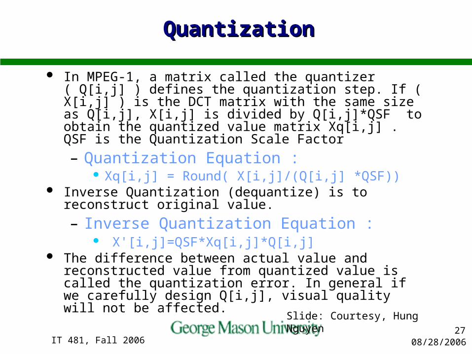
In MPEG-1, a matrix called the quantizer ( Q[i,j] ) defines the quantization step. If ( X[i,j] ) is the DCT matrix with the same size as Q[i,j], X[i,j] is divided by Q[i,j]*QSF to obtain the quantized value matrix Xq[i,j] . QSF is the Quantization Scale Factor
– Quantization Equation : Xq[i,j] = Round( X[i,j]/(Q[i,j] *QSF))
Inverse Quantization (dequantize) is to reconstruct original value.
– Inverse Quantization Equation : X'[i,j]=QSF*Xq[i,j]*Q[i,j]
The difference between actual value and reconstructed value from quantized value is called the quantization error. In general if we carefully design Q[i,j], visual quality will not be affected.
Slide: Courtesy, Hung Nguyen

08/28/2006IT 481, Fall 200628
Quantization (cont’d)Quantization (cont’d)
Slide: Courtesy, Hung Nguyen

08/28/2006IT 481, Fall 200629
Average Distribution of AC CoefficientsAverage Distribution of AC Coefficients
0 20 40 60 800
50Luminance Plane
0 20 40 60 800
50IQ Luminance Plane
0 20 40 60 800
20
40Cb Chrominance Plane
0 20 40 60 800
10
20IQ Cb Chrominance Plane
0 20 40 60 800
5
10Cr Chrominance Plane
0 20 40 60 800
5
10IQ Cr Chrominance Plane

08/28/2006IT 481, Fall 200630
MPEG (Moving Picture Expert Group)MPEG (Moving Picture Expert Group)
Established in January 1988 Operated in the framework of the Joint ISO/IEC
Technical Committee ISO: International Organization for Standardization IEC: International Electro-technical Commission First meeting was in May 1988 with 25 experts
participated Grown to 350 experts from 200 companies in some
20 countries As a rule, MPEG meets in March, July and
November & could be more often as needed
Slide: Courtesy, Hung Nguyen

08/28/2006IT 481, Fall 200631
MPEG-1 – Coding of Moving Pictures MPEG-1 – Coding of Moving Pictures and Associated Audioand Associated Audio
Request for Proposal (RFP) July 1989 Adopted in 1993 Coding of audiovisual signal at 1.5 Mbps Audio coding is separate from speech at
256 Kbps/per channel PCM Five parts: systems, video, audio,
conformance testing and software simulation
Slide: Courtesy, Hung Nguyen
08/28/2006IT 481, Fall 200632
MPEG-1 OverviewMPEG-1 Overview
In MPEG-1, video is represented as a sequence of pictures, and each picture is treated as a two-dimensional array of pixels (pixels)
The color of each pixel is consists of three components : Y (luminance), Cb and Cr (two chrominance components)– Composite video, aka baseband video or RCA video, is the
analog waveform that conveys the image data in a conventional National Television Standards Committee (NTSC) television signal
– Composite video contains chrominance (hue and saturation) and luminance (brightness) information, along with synchronization and blanking pulses
In order to achieve high compression ratio, MPEG-1 must use hybrid coding techniques to reduce both spatial redundancy and temporal redundancy
Slide: Courtesy, Hung Nguyen

08/28/2006IT 481, Fall 200633
MPEG-1 OverviewMPEG-1 Overview
Audio/video on CD-ROM (1.5 Mbps, CIF: 352x240)– Maximum: 1.856 mbps, 768x576 pixels
Start late 1988, test in 10/89, Committee Draft 9/90 ISO/IEC 11172-1~5 (Systems, video, audio,
compliance, software). Prompted explosion of digital video applications:
MPEG1 video CD and downloadable video over Internet
Software only decoding, made possible by the introduction of Pentium chips, key to the success in the commercial market
MPEG-1 Audio – Offers 3 coding options (3 layers), higher layer have higher
coding efficiency with more computations– MP3 = MPEG1 layer 3 audio Slide: Courtesy, Hung Nguyen

08/28/2006IT 481, Fall 200634
MPEG-2 vs. MPEG-1MPEG-2 vs. MPEG-1
MPEG-2 is a superset of MPEG-1. Generally, MPEG-1 is used for CD-ROM or Video
CD (VCD) and MPEG-2 is used for broadcast or DVD.
One current difference between MPEG-1 and MPEG-2 is that MPEG-2 has implemented variable bit rate.
MPEG-2 also is what’s known as a closed format, meaning that a license fee must be paid to use the decoding algorithms, where MPEG-1 can be implemented free of charge.
Slide: Courtesy, Hung Nguyen
08/28/2006IT 481, Fall 200635
MPEG2 vs. MPEG1 (cont’d)MPEG2 vs. MPEG1 (cont’d)
MPEG1 only handles progressive sequences specified by Source Input Format (SIF).
MPEG2 is targeted primarily at interlaced, as opposed to progressive for MPEG-1, sequences and at higher resolution.
Different DCT modes and scanning methods are developed for interlaced sequences.
More sophisticated motion estimation methods (frame/field prediction mode) are developed to improve estimation accuracy for interlaced sequences.
MPEG2 has various scalability modes. MPEG2 has various profiles and levels, each
combination targeted for a different applicationSlide: Courtesy, Hung Nguyen

08/28/2006IT 481, Fall 200636
MPEG EncodingMPEG Encoding
Frame TypesI Intra Encode complete image, similar to
JPEG
P Forward Predicted Motion relative to previous I and P’s
B Backward Predicted Motion relative to previous & future I’s & P’s
• • • • • •
I1 B1 B2 B3 P1 B4 B5 B6 P2 B7 B8 B9 I2
Slide: Courtesy, Hung Nguyen

08/28/2006IT 481, Fall 200637
– I frame complete
image– P frames provide
series of updates to most recent I frame
• • •• • •
I1
P1 P2
I2
updates
I1+P1 I1+P1+P2
Frame Reconstruction (I & P Frames Only)Frame Reconstruction (I & P Frames Only)
Slide: Courtesy, Hung Nguyen

08/28/2006IT 481, Fall 200638
Using Forward-Backward PredictionUsing Forward-Backward Prediction
If only forward prediction is used, there are uncovered areas (such as block behind car in Frame N) for which we may not be able to find a good match from the previous reference picture (Frame N-1).
On the other hand, backward prediction can properly predict these uncovered areas since they are available in the future reference picture, i.e. frame N+1 in this example.
New objects such as an airplane moving into the picture, cannot be predicted from the previous picture, but can be predicted from the future picture.
Backward PredictionForward Prediction
Slide: Courtesy, Hung Nguyen

08/28/2006IT 481, Fall 200639
– B frames interpolate between frames represented by I’s & P’s
• • •
I1 I2I1+P1 I1+P1+P2
• • •
B1 B2 B3 B4 B5 B6 B7 B8 B9
Interpolations
Frame Reconstruction (cont’d)Frame Reconstruction (cont’d)
Slide: Courtesy, Hung Nguyen
08/28/2006IT 481, Fall 200640
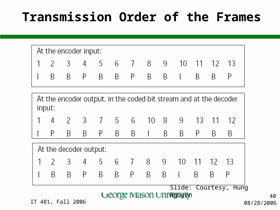
Transmission Order of the Frames
Slide: Courtesy, Hung Nguyen
08/28/2006IT 481, Fall 200641
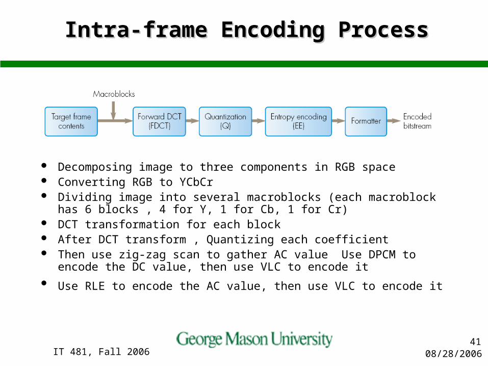
Intra-frame Encoding ProcessIntra-frame Encoding Process
Decomposing image to three components in RGB space Converting RGB to YCbCr Dividing image into several macroblocks (each macroblock has 6
blocks , 4 for Y, 1 for Cb, 1 for Cr) DCT transformation for each block After DCT transform , Quantizing each coefficient Then use zig-zag scan to gather AC value Use DPCM to encode the
DC value, then use VLC to encode it Use RLE to encode the AC value, then use VLC to encode it

08/28/2006IT 481, Fall 200642
I-Picture Encoding Flow ChartI-Picture Encoding Flow Chart
Slide: Courtesy, Hung Nguyen

08/28/2006IT 481, Fall 200643
08/28/2006IT 481, Fall 200644
Inter-frame CodingInter-frame Coding
The kind of pictures that are using the intra-frame coding technique are P pictures and B pictures
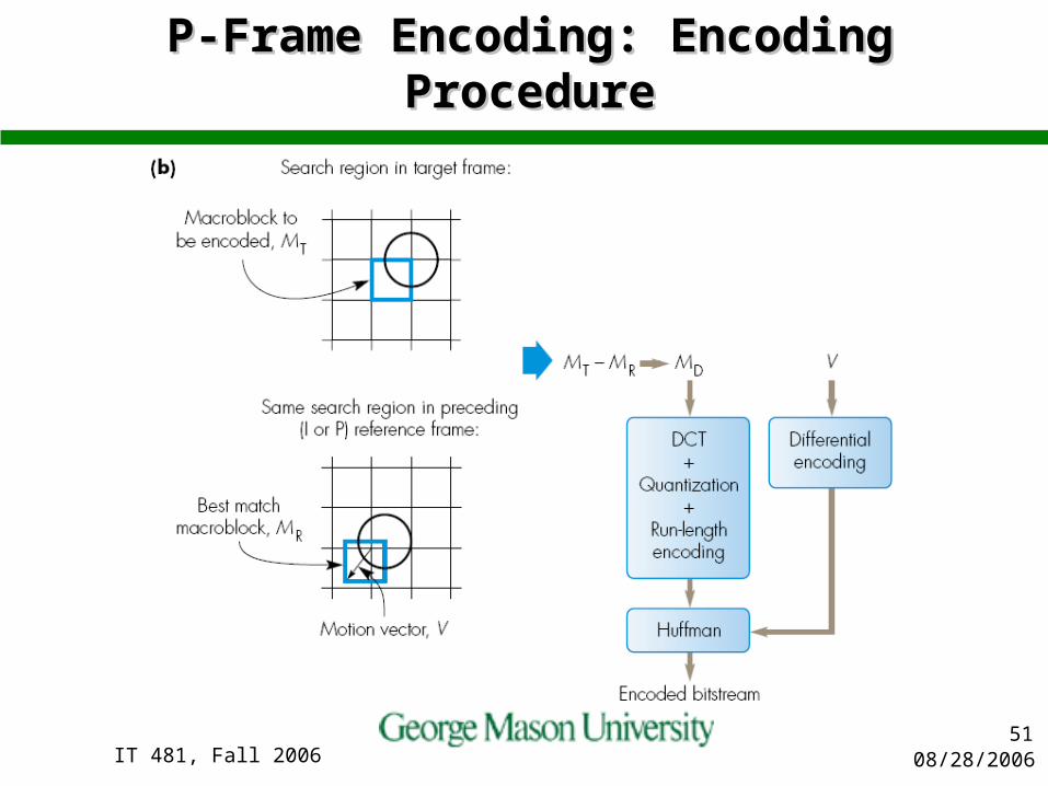
Coding of the P pictures is more complex than for I pictures, since motion-compensated macroblocks may be constructed– The difference between the motion compensated
macroblock and the current macroblock is transformed with a 2-dimensional DCT giving an array of 8 by 8 transform coefficients.
– The coefficients are quantized to produce a set of quantized coefficients. The quantized coefficients are then encoded using a run-length value technique.
Slide: Courtesy, Hung Nguyen
08/28/2006IT 481, Fall 200645
Inter-frame Encoding ProcessInter-frame Encoding Process
Decomposing image to three components in RGB space Converting RGB to YCbCr Perform motion estimation to record the difference between the
encoding frame and the reference frame stored within the frame buffer
Dividing image into several macroblocks (each macroblock has 6 blocks , 4 for Y, 1 for Cb, 1 for Cr)
DCT transformation for each block Quantizing each coefficient Use zig-zag scan to gather AC value Reconstruct the frame and store it to the frame buffer if necessary DPCM is applied to encode the DC value, then use VLC to encode it Use RLE to encode the AC value, then use VLC to encode it
Slide: Courtesy, Hung Nguyen
08/28/2006IT 481, Fall 200646
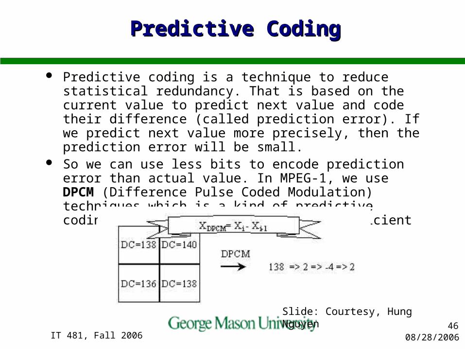
Predictive CodingPredictive Coding
Predictive coding is a technique to reduce statistical redundancy. That is based on the current value to predict next value and code their difference (called prediction error). If we predict next value more precisely, then the prediction error will be small.
So we can use less bits to encode prediction error than actual value. In MPEG-1, we use DPCM (Difference Pulse Coded Modulation) techniques which is a kind of predictive coding. And it is only used in DC coefficient
Slide: Courtesy, Hung Nguyen

08/28/2006IT 481, Fall 200647
Motion Compensation (MC) And Motion Compensation (MC) And Motion Estimation (ME)Motion Estimation (ME)
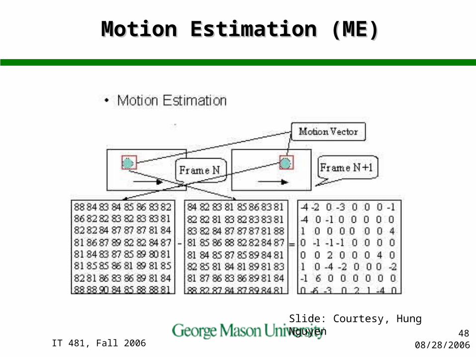
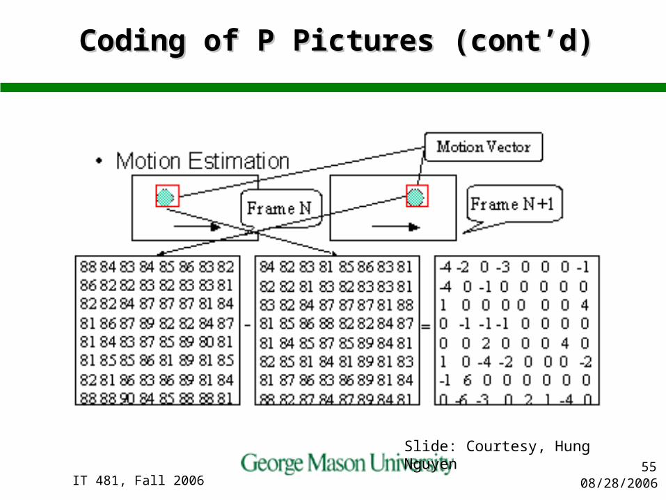
Motion Estimation is to predict a block of pixels' value in next picture using a block in current picture. The location difference between these blocks is called Motion Vector. And the difference between two blocks is called prediction error.
In MPEG-1, encoder must calculate the motion vector and prediction error. When decoder obtain these information , it can use this information and current picture to reconstruct the next picture.
We usually call this process as Motion Compensation. In general, motion compensation is the inverse process of motion Estimation Slide: Courtesy, Hung Nguyen
08/28/2006IT 481, Fall 200648
Motion Estimation (ME)Motion Estimation (ME)
Slide: Courtesy, Hung Nguyen

08/28/2006IT 481, Fall 200649
Motion Compensation (MC)Motion Compensation (MC)
Slide: Courtesy, Hung Nguyen

08/28/2006IT 481, Fall 200650
P-Frame Encoding: Macroblock P-Frame Encoding: Macroblock StructureStructure
08/28/2006IT 481, Fall 200651
P-Frame Encoding: Encoding ProcedureP-Frame Encoding: Encoding Procedure
08/28/2006IT 481, Fall 200652
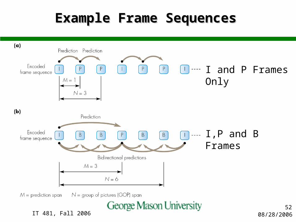
Example Frame Sequences Example Frame Sequences
I and P Frames Only
I,P and B Frames

08/28/2006IT 481, Fall 200653
Coding of P PicturesCoding of P Pictures
As in I pictures, the encoder needs to store the decoded P pictures since this may be used as the starting point for motion compensation. Therefore, the encoder will reconstruct the image from the quantized coefficients.
In coding P pictures, the encoder has more decisions to make than in the case of I pictures
– Selection of Macroblock Type: There are 8 types of macroblock in P pictures.
– Motion Compensation Decision: The encoder has an option on whether to transmit motion vectors or not for predictive-coded macroblocks.
– Intra/Non-intra Coding Decision Coded/Not Coded Decision:After quantization, if all the coefficients in a block is zero then the block is not coded.
– Quantizer/No Quantizer Decision: Quantizer scale can be altered which will affect the picture quality. Slide: Courtesy, Hung Nguyen

08/28/2006IT 481, Fall 200654
The Inter-frame Encoding Flow The Inter-frame Encoding Flow ChartChart
Slide: Courtesy, Hung Nguyen
08/28/2006IT 481, Fall 200655
Coding of P Pictures (cont’d)Coding of P Pictures (cont’d)
Slide: Courtesy, Hung Nguyen

08/28/2006IT 481, Fall 200656
Coding of B PicturesCoding of B Pictures
B pictures are divided into slices in the same way as I and P pictures. Since B pictures are not used as a reference for motion compensation, errors in B pictures are slightly less important than in I or P pictures. Consequently, it might be appropriate to use fewer slices for B pictures

08/28/2006IT 481, Fall 200657
Decisions to be made when Decisions to be made when coding the B picturescoding the B pictures
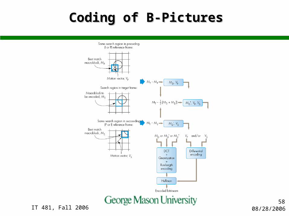
Selection of Macroblock Type: There are 12 types of macroblock in B pictures. Compare with P pictures, there are extra types due to the introduction of the backward motion vector. If both the backward and backward motion vectors are present, then motion-compensated macroblocks are constructed from both previous and future pictures, and the result is averaged to form the "interpolated" motion-compensated macroblock.
Selecting Motion Compensation Mode Intra/Non-Intra Coding Coded/Not Coded Decision Slide: Courtesy, Hung Nguyen
08/28/2006IT 481, Fall 200658
Coding of B-PicturesCoding of B-Pictures

08/28/2006IT 481, Fall 200659
Variable Length Coding (VLC)Variable Length Coding (VLC)
In MPEG-1, the last of all encoding processes is to use a Huffman Code to reduce data redundancy and the first step in decoding process is to decode VLC to reconstruct image data
Encoding and decoding processes with a Huffman Code must refer to a code table having two entries– The original data and the corresponding codeword. – In MPEG-1 standard , multiple code tables are defined in
MPEG-1 Standard 2-ANNEX C. The use of multiple code tables improves the compression ratio.
Slide: Courtesy, Hung Nguyen
08/28/2006IT 481, Fall 200660
MPEG-2 vs. MPEG-1MPEG-2 vs. MPEG-1
MPEG-2 is a superset of MPEG-1. Generally, MPEG-1 is used for CD-ROM or Video
CD (VCD) and MPEG-2 is used for broadcast or DVD.
One current difference between MPEG-1 and MPEG-2 is that MPEG-2 has implemented variable bit rate.
MPEG-2 also is what’s known as a closed format, meaning that a license fee must be paid to use the decoding algorithms, where MPEG-1 can be implemented free of charge.
Slide: Courtesy, Hung Nguyen

08/28/2006IT 481, Fall 200661
MPEG2 vs. MPEG1 (cont’d)MPEG2 vs. MPEG1 (cont’d)
MPEG1 only handles progressive sequences specified by Source Input Format (SIF).
MPEG2 is targeted primarily at interlaced, as opposed to progressive for MPEG-1, sequences and at higher resolution.
Different DCT modes and scanning methods are developed for interlaced sequences.
More sophisticated motion estimation methods (frame/field prediction mode) are developed to improve estimation accuracy for interlaced sequences.
MPEG2 has various scalability modes. MPEG2 has various profiles and levels, each
combination targeted for a different applicationSlide: Courtesy, Hung Nguyen

08/28/2006IT 481, Fall 200662
MPEG2 OverviewMPEG2 Overview
A/V broadcast (TV, HDTV, Terrestrial, Cable, Satellite, High Speed Inter/Intranet) as well as DVD video
4~8 Mbps for TV quality, 10-15 Mbps for better quality at SDTV resolutions (BT.601)
18-45 Mbps for HDTV applications– MPEG-2 video high profile at high level is the video coding
standard used in HDTV Test in 11/91, Committee Draft 11/93 ISO/IEC 13818-1~6 (Systems, video, audio, compliance,
software, DSM-CC) Consist of various profiles and levels Backward compatible with MPEG1 MPEG-2 Audio
– Support 5.1 channel– MPEG2 AAC (Advanced Audio Coding): requires 30% fewer bits
than, and not backward compatible with, MPEG1 layer 3 or MP3
Slide: Courtesy, Hung Nguyen
08/28/2006IT 481, Fall 200663
Features Supported by the MPEG-2 Algorithm
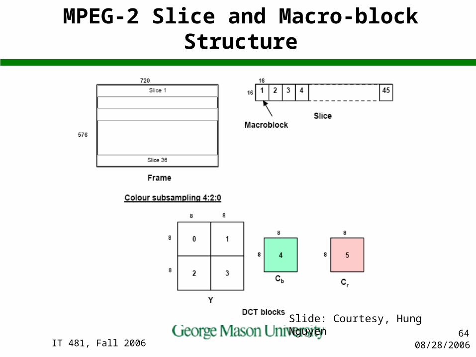
Different chrominance sampling formats (i.e., 4:2:0, 4:2:2, and 4:4:4) can be represented
Video in both the progressive and interlaced scan formats can be encoded
The decoder can use 3:2 pull down to represent a ~24 fps film as ~30 fps video
The displayed video can be selected by a movable pan-scan window within a larger raster
A wide range for picture qualities can be used Both constant an variable bit rate channels are supported ISO/IEC 11172-2 bit streams are decodable Bit streams for high and low (hardware) complexity decoders
can be generated Editing of encoded video is supported The encoded bit stream is resilient to errors
Slide: Courtesy, Hung Nguyen
08/28/2006IT 481, Fall 200664
MPEG-2 Slice and Macro-block Structure
Slide: Courtesy, Hung Nguyen
08/28/2006IT 481, Fall 200665
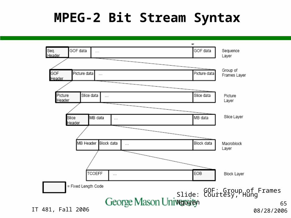
MPEG-2 Bit Stream Syntax
GOF: Group of FramesSlide: Courtesy, Hung Nguyen

08/28/2006IT 481, Fall 200666
Progressive vs. Interlaced ScanningProgressive vs. Interlaced Scanning
In the Interlaced video, each displayed frame consists of two interlaced fields, with the scanning lines in Field 1 located between the lines of Field 2.
On the contrary, the Progressive video has all the lines of a picture displayed in one frame. Thus, progressive video requires a higher picture rate than the frame-rate of an Interlaced video, to avoid a flickering display.
(a) Progressive Scan (b) Interlaced ScanSlide: Courtesy, Hung Nguyen

08/28/2006IT 481, Fall 200667
Disadvantage of Interlaced ScanningDisadvantage of Interlaced Scanning
A moving object may appear distorted when two fields are merged into a frame.
Since a moving ball will be at different locations in the two fields in the Interlaced Format, the ball will look distorted when two fields are put into a frame
Interlaced video also tends to cause horizontal picture details to dither thus introduces more high frequency noises
(a) Progressive Scan (b) Interlaced ScanSlide: Courtesy, Hung Nguyen
08/28/2006IT 481, Fall 200668
Field vs. Frame DCTField vs. Frame DCT
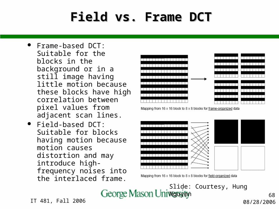
Frame-based DCT: Suitable for the blocks in the background or in a still image having little motion because these blocks have high correlation between pixel values from adjacent scan lines.
Field-based DCT: Suitable for blocks having motion because motion causes distortion and may introduce high-frequency noises into the interlaced frame.
Slide: Courtesy, Hung Nguyen
08/28/2006IT 481, Fall 200669
HDTV StandardsHDTV Standards
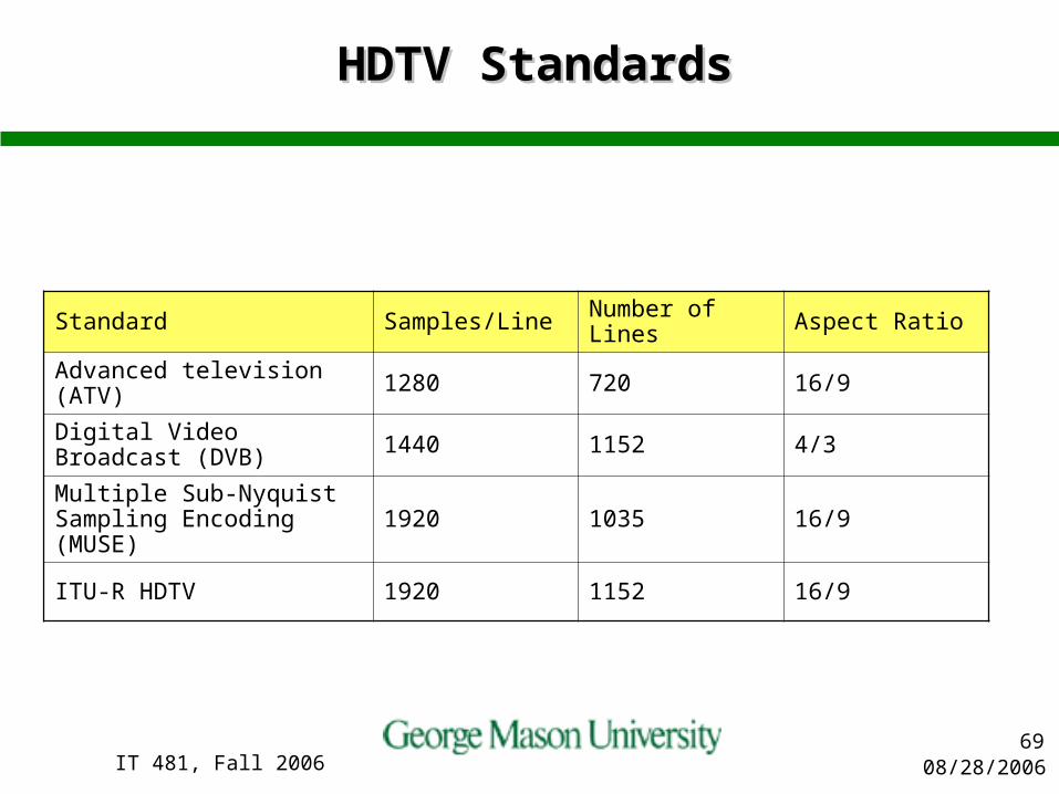
Standard Samples/Line Number of Lines Aspect Ratio
Advanced television (ATV) 1280 720 16/9
Digital Video Broadcast (DVB) 1440 1152 4/3
Multiple Sub-Nyquist Sampling Encoding (MUSE) 1920 1035 16/9
ITU-R HDTV 1920 1152 16/9

08/28/2006IT 481, Fall 200670
SummarySummary
H.261:– First video coding standard, targeted for video conferencing over
ISDN. Uses block-based hybrid coding framework with integer-pixel MC
H.263:– Improved quality at lower bit rate, to enable video
conferencing/telephony below 54 bkps (modems, desktop conferencing)
– Half-pixel MC and other improvement MPEG-1 video
– Video on CD and video on the Internet (good quality at 1.5 mbps)– Half-pixel MC and bidirectional MC
MPEG-2 video– SDTV/HDTV/DVD (4-15 mbps)– Extended from MPEG-1, considering interlaced video
Slide: Courtesy, Hung Nguyen


![IAC12/30/20 InspectionsandAppeals[481] 31 481—31.5(137F](https://img.pdfslide.net/doc/110x75/6266e12f0983034210142814/iac123020-inspectionsandappeals481-31-481315137f-.jpg)