Embed Size (px)
Citation preview
Concrete Shear Walls in RISAConcrete Shear Walls in RISA
Presenter:Presenter: Deborah Penko, P.E.Deborah Penko, P.E.
RISAFloor 6.0
RISA‐3D 10.0
Concrete Wall Design ProgramsConcrete Wall Design Programs
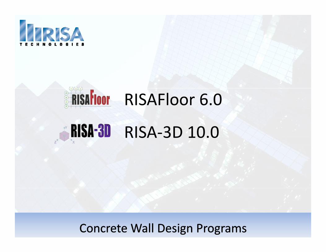
Modeling Walls in RISAModeling Walls in RISA
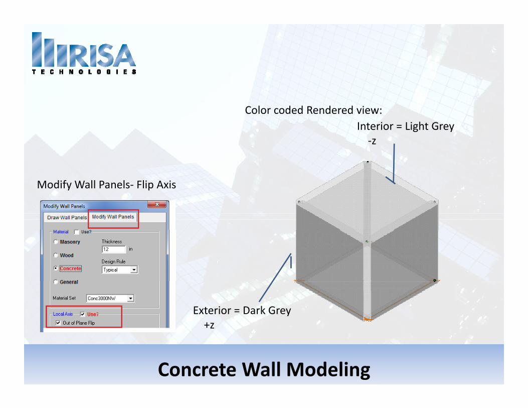
Interior = Light GreyColor coded Rendered view:
Interior = Light Grey‐z
Modify Wall Panels‐ Flip Axis
Exterior = Dark Grey+z
Concrete Wall Modeling
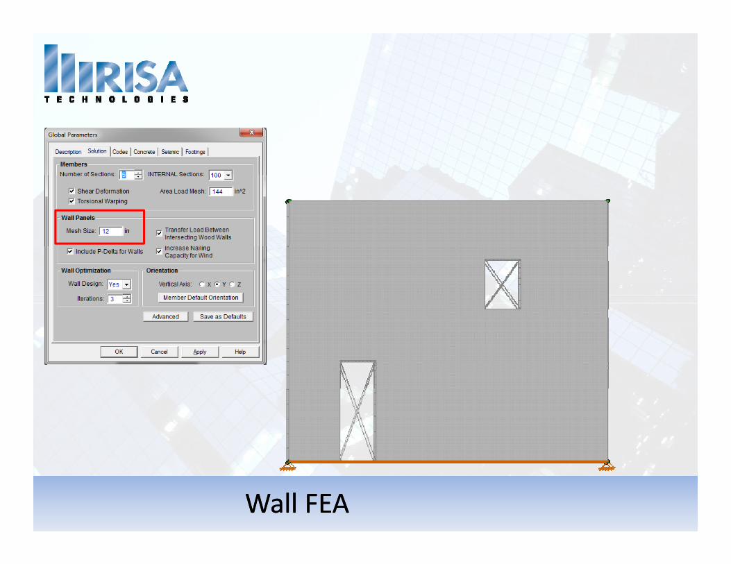
Wall FEAWall FEA
Automatic MeshingLine or point constraints created in the wall.
• Openings
• Loads• Loads
• Intersected by another wall panel
• Diaphragms
• Beams or plate elements
• Nodes
Wall MeshWall Mesh
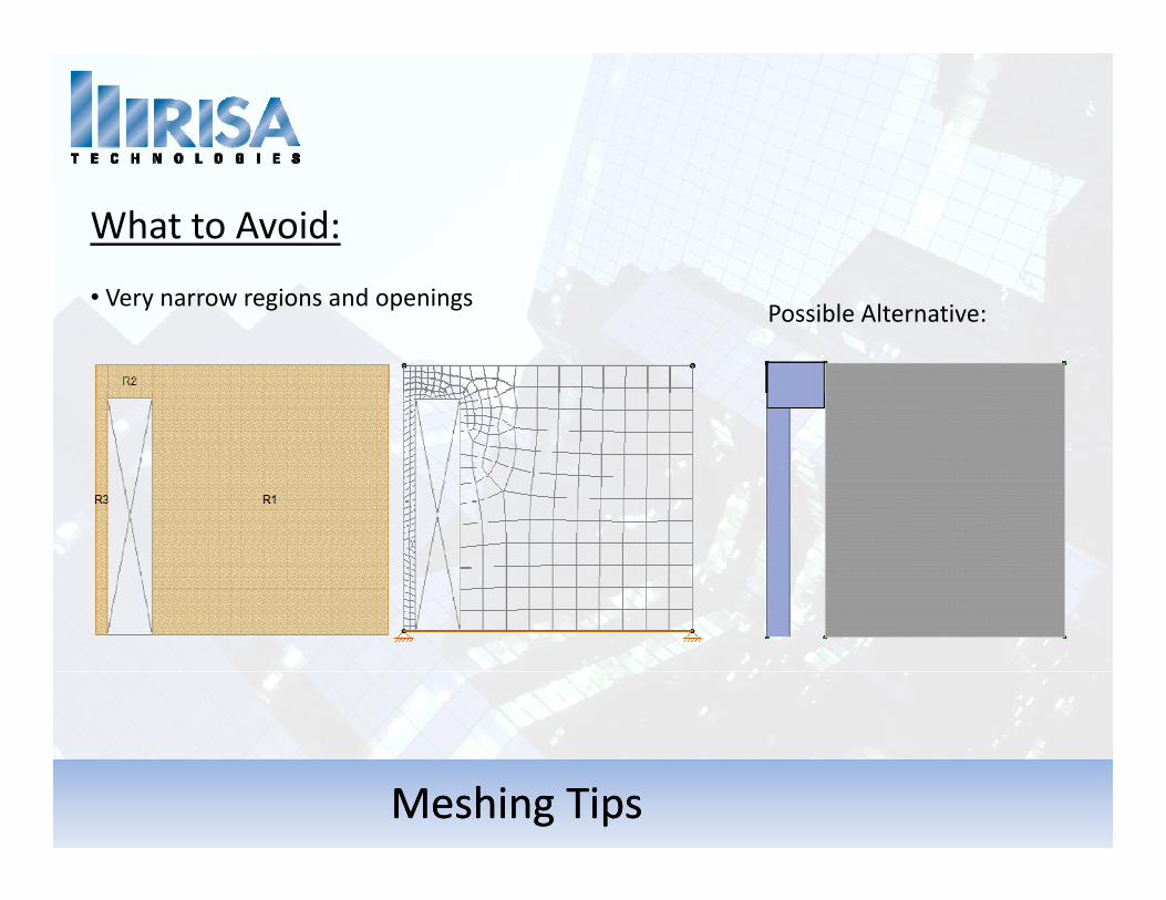
What to Avoid:
• Very narrow regions and openingsPossible Alternative:
Meshing TipsMeshing Tips
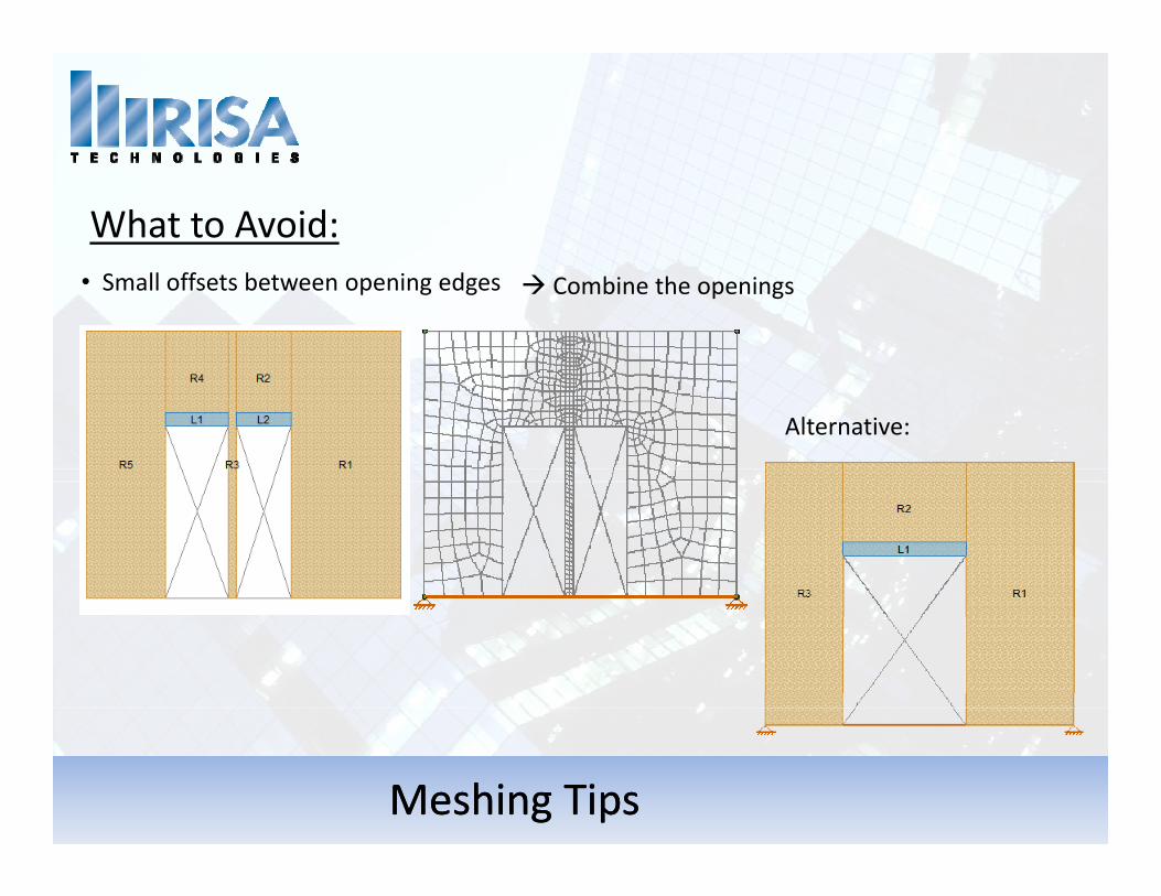
• Small offsets between opening edges C bi th i
What to Avoid:• Small offsets between opening edges Combine the openings
Alternative:
Meshing TipsMeshing Tips
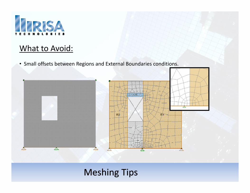
What to Avoid:
• Small offsets between Regions and External Boundaries conditions.
Meshing TipsMeshing Tips
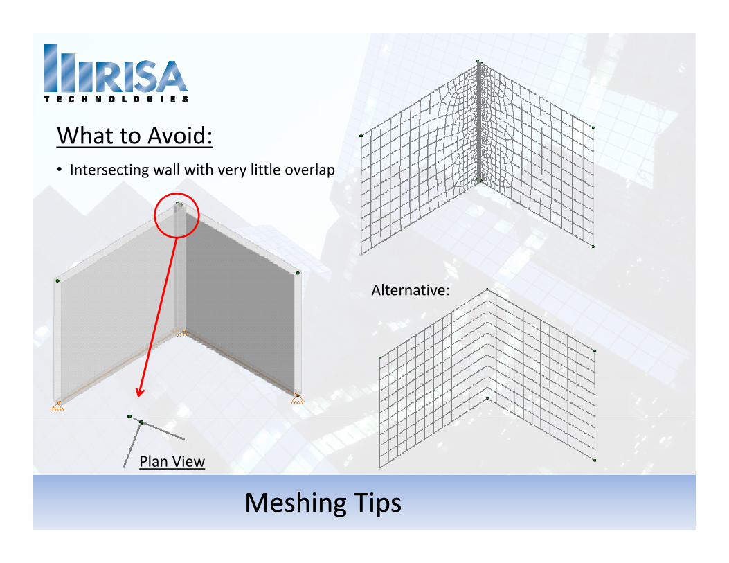
What to Avoid:• Intersecting wall with very little overlapg y p
Alternative:
Plan View
Meshing TipsMeshing Tips
Plan View
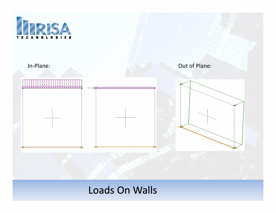
In‐Plane: Out of Plane:In‐Plane: Out of Plane:
Loads On WallsLoads On Walls
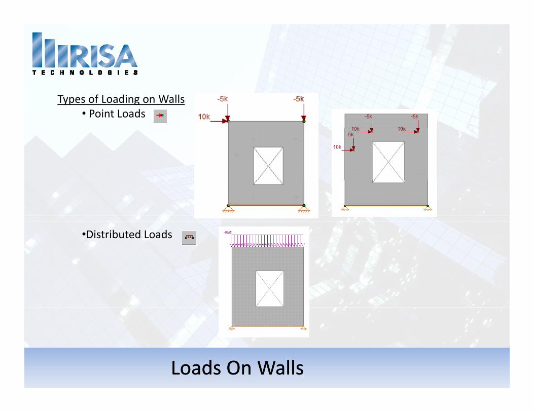
Types of Loading on Walls• Point Loads
Di t ib t d L d•Distributed Loads
Loads On WallsLoads On Walls
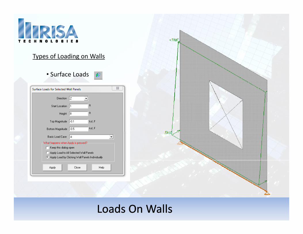
Types of Loading on Walls
S f L d• Surface Loads
Loads On WallsLoads On Walls
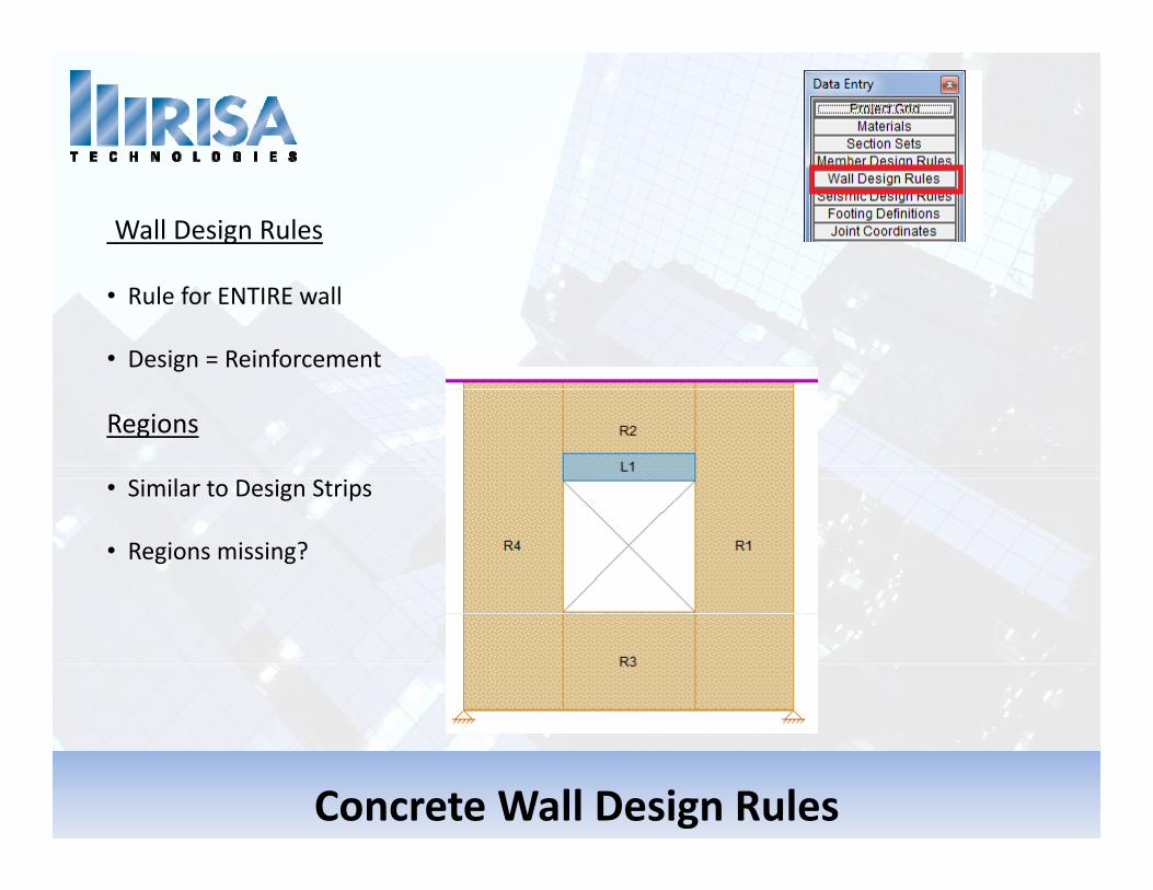
Wall Design Rules
• Rule for ENTIRE wall
• Design = Reinforcement
Regions
• Similar to Design Strips
• Regions missing?
Concrete Wall Design Rules
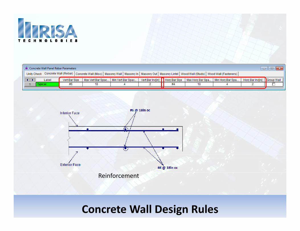
Reinforcement
Concrete Wall Design Rules
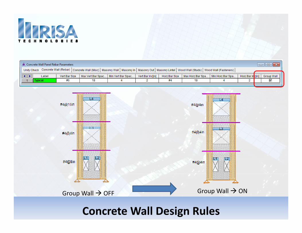
Group Wall ON
Concrete Wall Design Rules
Group Wall OFF Group Wall ON
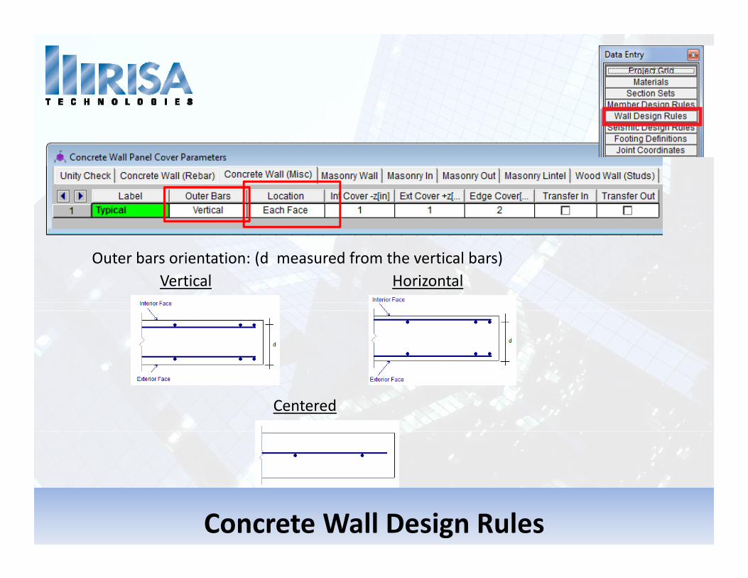
O b i i (d d f h i l b )Outer bars orientation: (d measured from the vertical bars)HorizontalVertical
Centered
Concrete Wall Design Rules
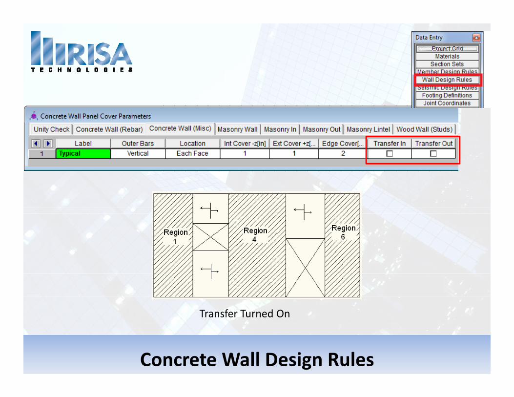
Transfer Turned On
Concrete Wall Design Rules
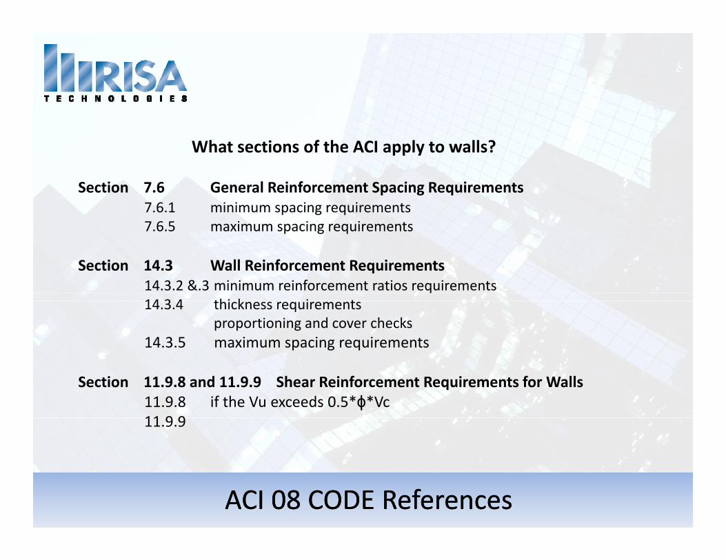
What sections of the ACI apply to walls?
Section 7.6 General Reinforcement Spacing Requirements7.6.1 minimum spacing requirements 7.6.5 maximum spacing requirements
Section 14.3 Wall Reinforcement Requirements14.3.2 &.3 minimum reinforcement ratios requirements 14.3.4 thickness requirements
proportioning and cover checks14.3.5 maximum spacing requirements
Section 11.9.8 and 11.9.9 Shear Reinforcement Requirements for WallsSection 11.9.8 and 11.9.9 Shear Reinforcement Requirements for Walls11.9.8 if the Vu exceeds 0.5*ϕ*Vc11.9.9
ACI 08 CODE ReferencesACI 08 CODE References
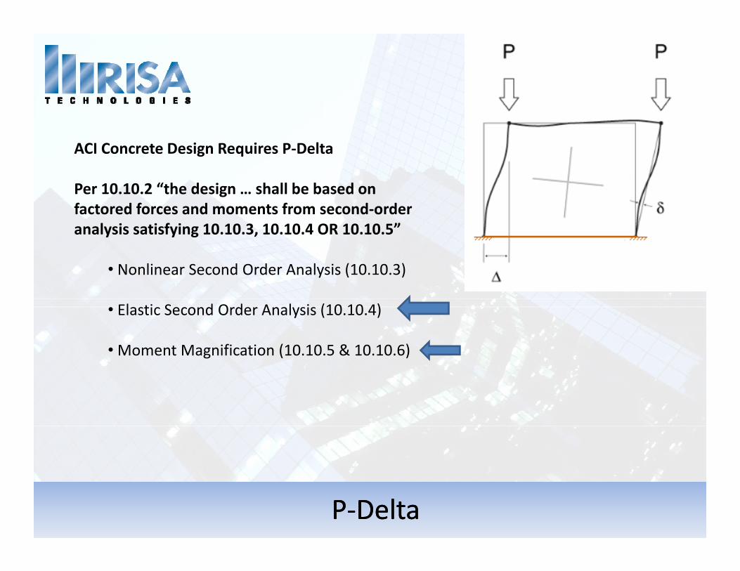
ACI Concrete Design Requires P‐Delta
Per 10.10.2 “the design … shall be based on factored forces and moments from second‐order analysis satisfying 10.10.3, 10.10.4 OR 10.10.5”
• Nonlinear Second Order Analysis (10.10.3)
• Elastic Second Order Analysis (10.10.4)
•Moment Magnification (10.10.5 & 10.10.6)
PP‐‐DeltaDelta
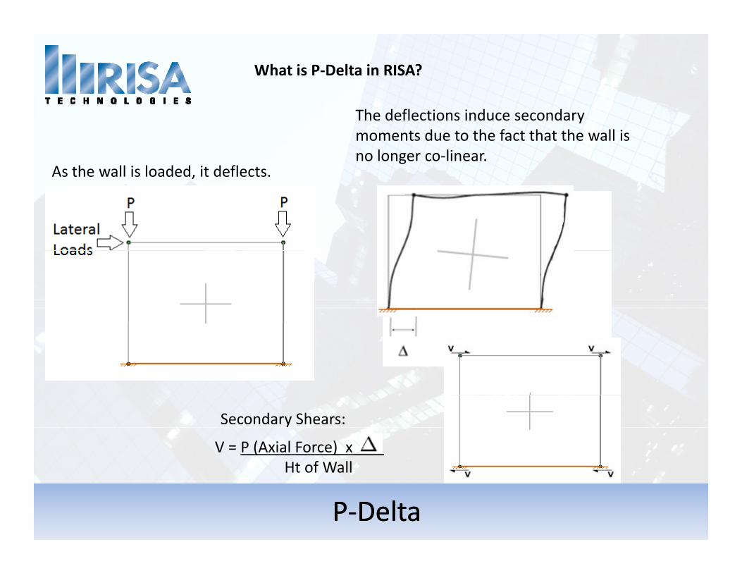
What is P‐Delta in RISA?
As the wall is loaded, it deflects.
The deflections induce secondary moments due to the fact that the wall is no longer co‐linear.
,
V = P (Axial Force) x . Ht of Wall
Secondary Shears:
PP‐‐DeltaDelta
Ht of Wall
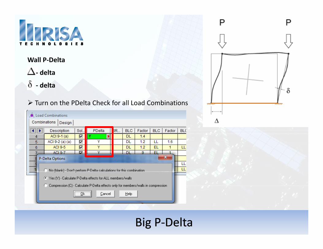
Wall P‐Delta
‐ delta
‐ delta
Turn on the PDelta Check for all Load Combinations
Big PBig P‐‐DeltaDelta
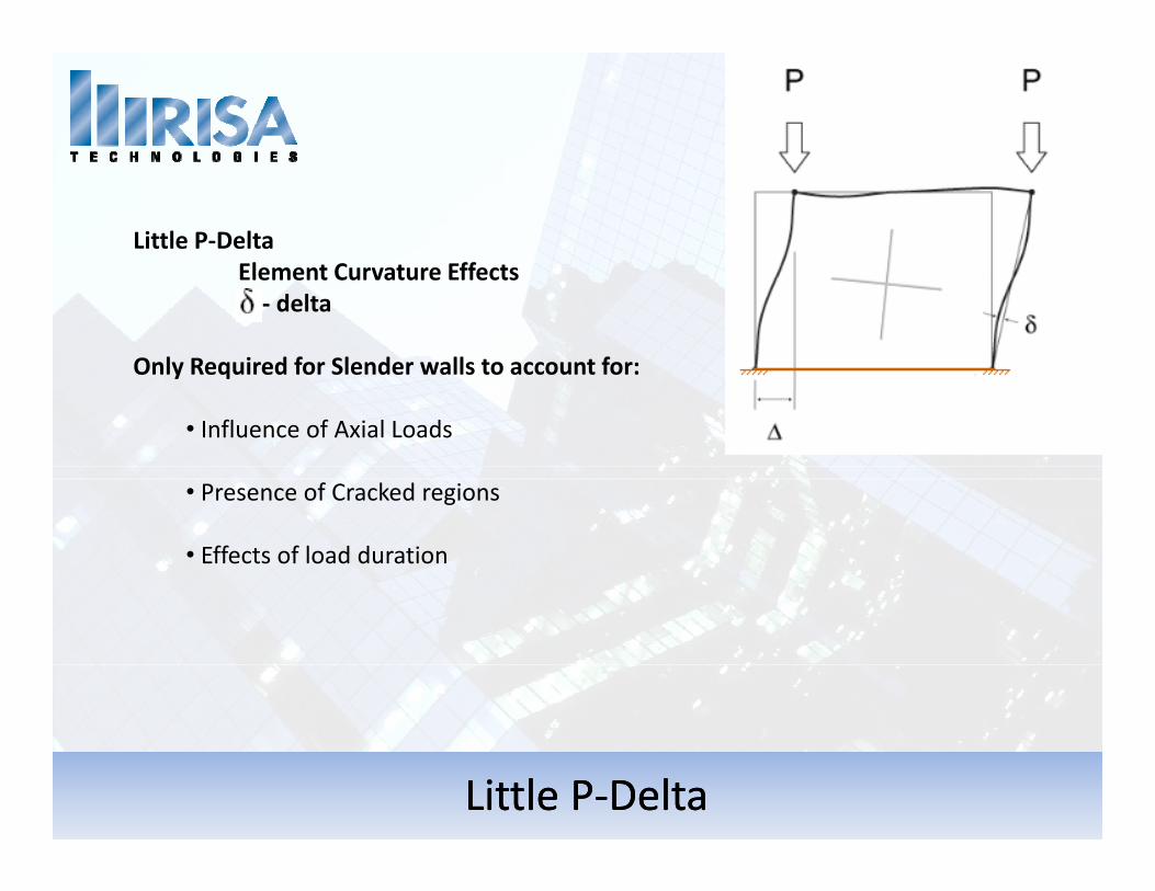
Little P‐DeltaElement Curvature EffectsElement Curvature Effects‐ delta
Only Required for Slender walls to account for:
• Influence of Axial Loads
• Presence of Cracked regionsg
• Effects of load duration
Little PLittle P‐‐DeltaDelta
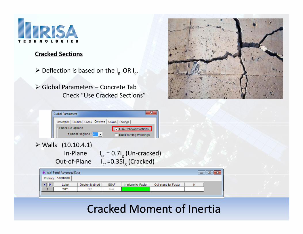
Cracked Sections
Deflection is based on the Ig OR Icrg cr
Global Parameters – Concrete TabCheck “Use Cracked Sections”
Walls (10.10.4.1)In‐Plane Icr = 0.7Ig (Un‐cracked)
Out of Plane I =0 35I (Cracked)Out‐of‐Plane Icr =0.35Ig (Cracked)
Cracked Moment of InertiaCracked Moment of Inertia

Questions?
Please let us know if you have questions.
We will answer as many questions as time permits during the webinar.
Once the webinar is closed we will post all Q&A’s to ourOnce the webinar is closed, we will post all Q&As to our website: www.risa.com
For further information, contact us at: [email protected]
Presenter:Presenter: Deborah Brisbin, P.E.Deborah Brisbin, P.E.
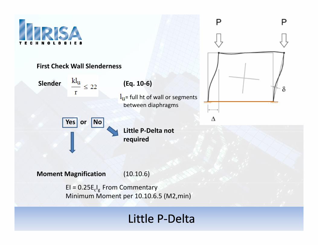
First Check Wall Slenderness
Slender (Eq. 10‐6)
= full ht of wall or segments between diaphragms p g
Yes or No Little P‐Delta not req iredrequired
Moment Magnification (10.10.6)
EI = 0.25EcIg From CommentaryMinimum Moment per 10.10.6.5 (M2,min)
Little PLittle P‐‐DeltaDelta