Embed Size (px)
Citation preview
Installation and Operating Instructions (English)Instrucciones de Montaje y de Uso (Español)Instructions de Montage et de Service (Français)Manual de Instalação e de Instrucções (Português)
This manual contains important safety information and should be made available to all personnel who operate and/or maintain this product. Carefully read this manual before attempting to operate or perform maintenance on this equipment.
Manual No. 65102-3A
July 2005 Edition
Q MAT 03Q MAT HP 1000
Condensate Drain

Table of Contents
EnglishIntroduction ........................................................................................................................ 1
Safety Rules ........................................................................................................................ 2
Function ............................................................................................................................. 4
Installation .......................................................................................................................... 8
Installation ........................................................................................................................ 10
Installation ........................................................................................................................ 12
Electrical Installation ......................................................................................................... 14
Electrical Data .................................................................................................................. 18
Maintenance ..................................................................................................................... 20
Troubleshooting ............................................................................................................... 22
Components ..................................................................................................................... 26
Replacement Parts ............................................................................................................ 30
Dimensions ....................................................................................................................... 32
Accessories ....................................................................................................................... 32
Data/Notes ....................................................................................................................... 33
EspañolIntroducción ....................................................................................................................... 1
Indicaciones de Seguridad ................................................................................................. 2
Funcionamiento ................................................................................................................. 5
Instalación .......................................................................................................................... 8
Instalación ........................................................................................................................ 10
Instalación ........................................................................................................................ 12
Instalación Eléctrica .......................................................................................................... 15
Caracteristicas eléctricas .................................................................................................. 18
Mantenimiento ................................................................................................................. 20
Búsqueda de fallos ........................................................................................................... 23
Componentes .................................................................................................................. 27
Piezas De Recambio ......................................................................................................... 30
Dimensiones ..................................................................................................................... 32
Accesorios ........................................................................................................................ 32
Caracteristicas/Indicaciones ............................................................................................. 33
Quincy Compressor-Q MAT 03/Q MAT HP 1000 Condensate Drain
Table of Contents
FrançaisIntroduction ........................................................................................................................ 1
Consignes de Sécurité ........................................................................................................ 3
Fonctionnement ................................................................................................................. 6
Installation .......................................................................................................................... 9
Installation ........................................................................................................................ 11
Installation ........................................................................................................................ 13
Installation électrique ....................................................................................................... 16
Charactéristiques electrique ............................................................................................. 19
Entretien ........................................................................................................................... 21
Recherche de panne ......................................................................................................... 24
Nomenclature des Pièces ................................................................................................. 28
Pièces De Rechange ......................................................................................................... 31
Dimensions ....................................................................................................................... 32
Accessoires ....................................................................................................................... 32
Characteristiques/Avis ...................................................................................................... 33
PortuguêsIntroduziste ......................................................................................................................... 1
Instruções de Segurança .................................................................................................... 3
Funcionamento ................................................................................................................... 7
Instalação ........................................................................................................................... 9
Instalação ......................................................................................................................... 11
Instalação ......................................................................................................................... 13
Instalação Eléctrica ........................................................................................................... 17
Dados eléctricos ............................................................................................................... 19
Manutenção ..................................................................................................................... 21
Localização de avarias ...................................................................................................... 25
Componentes ................................................................................................................... 29
Peças De Recolocação ..................................................................................................... 31
Dimensões ........................................................................................................................ 32
Acessórios ........................................................................................................................ 32
Dados/Características ....................................................................................................... 33
Quincy Compressor-Q MAT 03/Q MAT HP 1000 Condensate Drain
Introduction
Thank you for purchasing the Q MAT condensate drain. Please read these instructions carefully before installing your Q MAT unit and putting it into service. Correct function of the Q MAT condensate drain - and thus reliable condensate discharge - can only be guaranteed if the recommendations and conditions stated here are adhered to.
Introducción
Les agradecemos que hayan decidido adquirir un Q MAT. Para garantizar un funcionamiento fiable, les rogamos que observen las indicaciones del manual del Q MAT. Siendo así, les podemos dar la garantía de un funcionamiento correcto del Q MAT y en consecuencia una evacuación fiable de los condensados.
Introduction
Vous venez d’acquérir un purgeur de condensât Q MAT et nous vous en félicitons. Nous vous recommandons de lire attentivement ces instructions avant le montage et la mise en service du Q MAT et de suivre nos conseils. Car, seul le respect scupuleux des prescriptions et consignes données, peut garantir le parfait fonctionnement du Q MAT et une purge fiable du condensât.
Introduziste
Muito obrigado por se ter decidido pelo Q MAT. Leia, por favor, com atenção estas instruções de instalação e de serviço antes de montar e colocar em funcionamento o Q MAT e observe as nossas indicações. Só poderemos garantir um funcionamento correto e um escoamento seguro do condensado se as instruções e indicações forem rigorosamente respeitadas.
Quincy Compressor-Q MAT 03/Q MAT HP 1000 Condensate Drain 1
1. Do not exceed maximum operating pressure (see type plate).
NOTE:Maintenance work must only be carried out when the device is not under pressure.
2. Use only pressure-proof installation material. The feed line (1/2”) must be firmly fixed. Discharge line: short pressure hose to pressure-proof pipe. Please ensure that condensate cannot squirt onto persons or objects.
3. Use only NPT fittings for the threaded connections.
4. For locking or holding in position during installation, use spanner area at inflow point. Spanner size 1.25”.
5. The electrical installation must be carried out in compliance with the valid regulations.
Safety Rules
NOTE:Maintenance work is only allowed when the device is in a de-energized condition. Electrical work must always be performed by a qualified electrician.
6. In areas where there is danger of frost, the Q MAT device should be retrofitted with a thermostatically controlled heater (see accessories).
7. The Q MAT condensate drain will only function when voltage is being applied to the device.
8. Do not use the test button for continuous draining.
9. Do not use the Q MAT device in hazardous areas (with potentially explosive atmospheres).
10. Use only original spare parts, otherwise the guarantee will no longer be valid.
1. No sobrepase la presión máxima. (ver etiqueta de identificación).
¡ATENCIÓN! Realice los trabajos de mantenimiento solo si el aparato se encuentra sin presión.
2. Utilice solamente los accesorios y la tubería flexible autorizados para la presión conectada. La tubería de la entrada de los condensados (1/2”) tiene que estar bien fijada. Salida de condensado: Un tubo flexible resistente a la presión unido a un tubo fijo resistente a la presión. Evite que personas o objetos pueden ser alcanzadas por el condensado.
3. Utilice solamente las guarniciones de NPT para las conexiones rascados.
4. Para el aguante o el giro durante la instalación utilice el área de la entrada de los condensados preparada para acoger una llave. SW No. 32.
5. Ejecute la instalación eléctrica según las normas vigentes.
¡ATENCIÓN! Realice los trabajos de mantenimiento con el aparato desconectado. Los trabajos eléctricos sólo deben ser rea l i zados por per sona l especializado.
6. En zonas con peligro de heladas monte la calefacción regulada por termostato.
7. El Q MAT sólo funciona si esta conectado a la corriente eléctrica.
8. No utilice el interruptor de “TEST” para la purga continua.
9. No utilice el Q MAT en áreas con peligro de explosiones.
10. Solamente utilice recambios originales. En caso contrario se cancela la garantía.
Indicaciones de Seguridad
2 Quincy Compressor-Q MAT 03/Q MAT HP 1000 Condensate Drain
Consignes de Sécurité
1. Ne pas dépasser la pression de service maximale (voir plaque signalétique).
ATTENTION!Dépressuriser le purgeur avant toute intervention d’entretien.
2. N’utiliser que du matériel d’installation résistant à la pression. Conduite d’arrivée: toujours en tuyauterie rigide et fixe (1/2”). Conduite d’évacuation: flexible de faible longueur relié à un tube, tous deux résistant à la pression. Évitez que des personnes ou objets puissent être touchés par le condensât.
3. Utilisez seulement les garnitures de NPT pour les raccordements filetés.
4. Lors du montage, utiliser le méplat pour clé de 32mm situé à l’entrée du purgeur.
5. Lors de l’installation électrique, respecter toutes les prescriptions en vigueur (VDE 0100).
ATTENTION!Avant toute intervent ion de maintenance, mettre l’installation hors tension. Toute intervention électr ique doit être réal isée exclusivement par un personnel qualifié et autorisé.
6. En cas de risque de gel, rajouter un chauffage thermostatique (accessoires).
7. Le Q MAT n’est opérationnel que s’il est sous tension.
8. Ne pas utiliser la touche Test pour une purge permanente.
9. Ne pas utiliser le Q MAT dans les atmosphères explosibles.
10. Utiliser exclusivement des pièces de rechange d’origine. Dans le cas contraire, la garantie est annulée.
Instruções de Segurança
1. Não exceder a pressão de serviço máxima (ver placa indicador das características).
ATENÇÃO! Só efetuar trabalhos de manutenção com o aparelho isento de pressão.
2. Só utilizar material de instalação resistente à pressão. A tubagem de entrada dos condensados (1/2’’) tem que estar bem fixa. Um tubo flexível resistente à pressão, unido a um tubo rígido também resistente à pressão. Evite que pessoas ou objetos possam atingidos pela descarga do condensado.
3. Use somente os encaixes de NPT para as conexões enfiadas.
4. Para modar ou segurar de encontro durante a instalação, utilizar a caixa de chave (SW32) no ponto de afluência.
5. Executar a instalação eléctrica em concordância com todas as normas vigentes (VDE 0100).
ATENÇÃO! Só efetuar trabalhos de manutenção com o aparelho isento de pressão. Todos os trabalhos eléctricos só poderão ser executados por pessoal técnico autorizado.
6. Nas áreas onde há um perigo da geada, o dispositivo MAT de Q deve ser adaptado com um calefator termostàtica controlado (veja acessórios).
7. O Q MAT só funcionará se estiver ligado à corrente eléctrica.
8. Não utilizar o botão de teste para escoamento permanente.
9. Não utilizar o Q MAT em áreas potencialmente explosivas.
10. Só utilizar peças sobressalentes originais. Caso contrário, extinguirá a garantia.
Quincy Compressor-Q MAT 03/Q MAT HP 1000 Condensate Drain 3
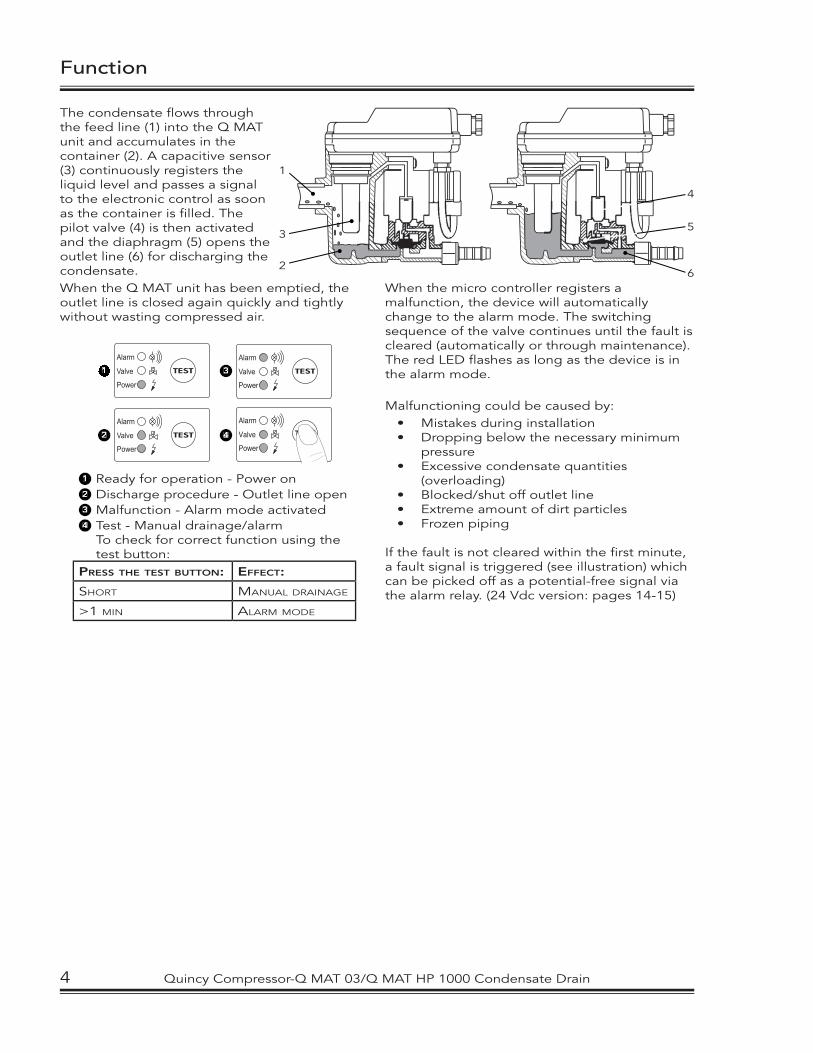
The condensate fl ows through the feed line (1) into the Q MAT unit and accumulates in the container (2). A capacitive sensor (3) continuously registers the liquid level and passes a signal to the electronic control as soon as the container is fi lled. The pilot valve (4) is then activated and the diaphragm (5) opens the outlet line (6) for discharging the condensate. When the Q MAT unit has been emptied, the outlet line is closed again quickly and tightly without wasting compressed air.
TEST
Power
Alarm
Valve11
TEST
Power
Alarm
Valve22
TEST
Power
Alarm
Valve33
TEST
Power
Alarm
Valve44
11 Ready for operation - Power on22 Discharge procedure - Outlet line open33 Malfunction - Alarm mode activated44 Test - Manual drainage/alarm
To check for correct function using the test button:
PRESS THE TEST BUTTON: EFFECT:
SHORT MANUAL DRAINAGE
>1 MIN ALARM MODE
Function
1
2
3
4
5
6When the micro controller registers a malfunction, the device will automatically change to the alarm mode. The switching sequence of the valve continues until the fault is cleared (automatically or through maintenance). The red LED fl ashes as long as the device is in the alarm mode.
Malfunctioning could be caused by: • Mistakes during installation• Dropping below the necessary minimum
pressure• Excessive condensate quantities
(overloading)• Blocked/shut off outlet line• Extreme amount of dirt particles• Frozen piping
If the fault is not cleared within the fi rst minute, a fault signal is triggered (see illustration) which can be picked off as a potential-free signal via the alarm relay. (24 Vdc version: pages 14-15)
4 Quincy Compressor-Q MAT 03/Q MAT HP 1000 Condensate Drain
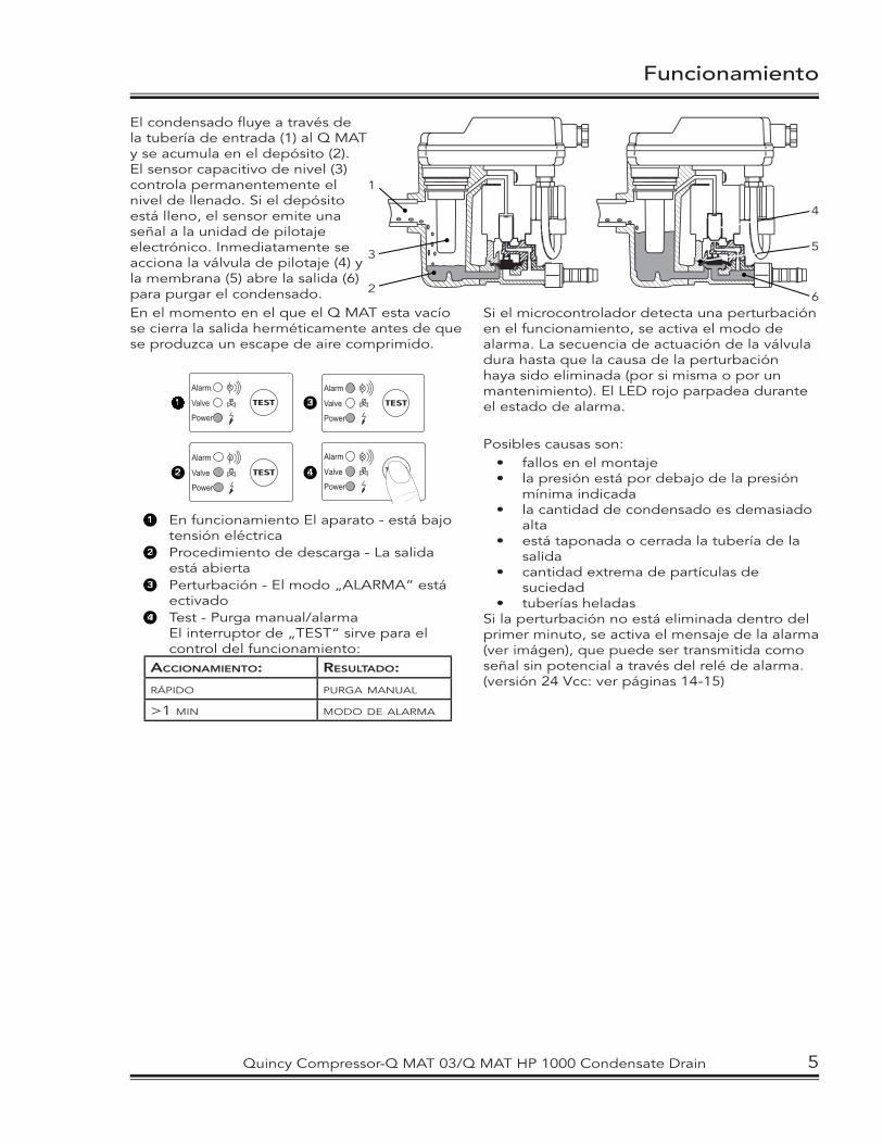
El condensado fl uye a través de la tubería de entrada (1) al Q MAT y se acumula en el depósito (2). El sensor capacitivo de nivel (3) controla permanentemente el nivel de llenado. Si el depósito está lleno, el sensor emite una señal a la unidad de pilotaje electrónico. Inmediatamente se acciona la válvula de pilotaje (4) y la membrana (5) abre la salida (6) para purgar el condensado. En el momento en el que el Q MAT esta vacío se cierra la salida herméticamente antes de que se produzca un escape de aire comprimido.
TEST
Power
Alarm
Valve11
TEST
Power
Alarm
Valve22
TEST
Power
Alarm
Valve33
TEST
Power
Alarm
Valve44
11 En funcionamiento El aparato - está bajo tensión eléctrica
22 Procedimiento de descarga - La salida está abierta
33 Perturbación - El modo „ALARMA“ está ectivado
44 Test - Purga manual/alarma El interruptor de „TEST“ sirve para el
control del funcionamiento:ACCIONAMIENTO: RESULTADO:
RÁPIDO PURGA MANUAL
>1 MIN MODO DE ALARMA
1
2
3
4
5
6
Funcionamiento
Si el microcontrolador detecta una perturbación en el funcionamiento, se activa el modo de alarma. La secuencia de actuación de la válvula dura hasta que la causa de la perturbación haya sido eliminada (por si misma o por un mantenimiento). El LED rojo parpadea durante el estado de alarma.
Posibles causas son:• fallos en el montaje• la presión está por debajo de la presión
mínima indicada• la cantidad de condensado es demasiado
alta• está taponada o cerrada la tubería de la
salida• cantidad extrema de partículas de
suciedad• tuberías heladas
Si la perturbación no está eliminada dentro del primer minuto, se activa el mensaje de la alarma (ver imágen), que puede ser transmitida como señal sin potencial a través del relé de alarma. (versión 24 Vcc: ver páginas 14-15)
Quincy Compressor-Q MAT 03/Q MAT HP 1000 Condensate Drain 5
Fonctionnement
1
2
3
4
5
6
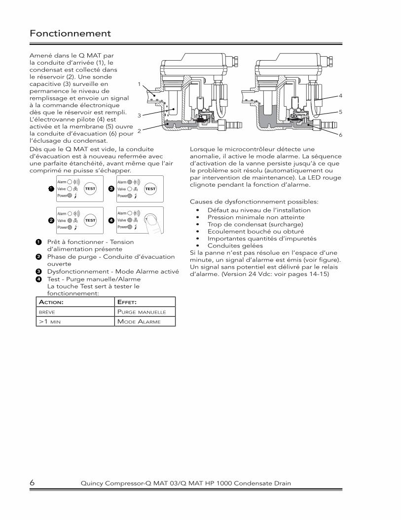
Amené dans le Q MAT par la conduite d’arrivée (1), le condensat est collecté dans le réservoir (2). Une sonde capacitive (3) surveille en permanence le niveau de remplissage et envoie un signal à la commande électronique dès que le réservoir est rempli. L’électrovanne pilote (4) est activée et la membrane (5) ouvre la conduite d’évacuation (6) pour l’éclusage du condensat. Dès que le Q MAT est vide, la conduite d’évacuation est à nouveau refermée avec une parfaite étanchéité, avant même que l’air comprimé ne puisse s’échapper.
TEST
Power
Alarm
Valve11
TEST
Power
Alarm
Valve22
TEST
Power
Alarm
Valve33
TEST
Power
Alarm
Valve44
11 Prêt à fonctionner - Tension d’alimentation présente
22 Phase de purge - Conduite d’évacuation ouverte
33 Dysfonctionnement - Mode Alarme activé44 Test - Purge manuelle/Alarme La touche Test sert à tester le
fonctionnement:ACTION: EFFET:
BRÈVE PURGE MANUELLE
>1 MIN MODE ALARME
Lorsque le microcontrôleur détecte une anomalie, il active le mode alarme. La séquence d’activation de la vanne persiste jusqu’à ce que le problème soit résolu (automatiquement ou par intervention de maintenance). La LED rouge clignote pendant la fonction d’alarme.
Causes de dysfonctionnement possibles:• Défaut au niveau de l’installation• Pression minimale non atteinte• Trop de condensat (surcharge)• Ecoulement bouché ou obturé• Importantes quantités d’impuretés• Conduites gelées
Si la panne n’est pas résolue en l’espace d’une minute, un signal d’alarme est émis (voir fi gure). Un signal sans potentiel est délivré par le relais d’alarme. (Version 24 Vdc: voir pages 14-15)
6 Quincy Compressor-Q MAT 03/Q MAT HP 1000 Condensate Drain
Funcionamento
1
2
3
4
5
6
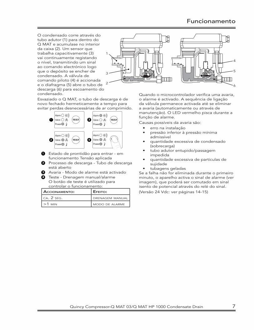
O condensado corre através do tubo adutor (1) para dentro do Q MAT e acumulase no interior da caixa (2). Um sensor que trabalha capacitivamente (3) vai continuamente registando o nível, transmitindo um sinal ao comando electrónico logo que o depósito se encher de condensado. A válvula de comando piloto (4) é accionada e o diafragma (5) abre o tubo de descarga (6) para escoamento do condensado.Esvaziado o Q MAT, o tubo de descarga é de novo fechado hermeticamente a tempo para evitar perdas desnecessárias de ar comprimido.
TEST
Power
Alarm
Valve11
TEST
Power
Alarm
Valve22
TEST
Power
Alarm
Valve33
TEST
Power
Alarm
Valve44
11 Estado de prontidão para entrar - em funcionamento Tensão aplicada
22 Processo de descarga - Tubo de descarga está aberto
33 Avaria - Modo de alarme está activado44 Teste - Drenagem manual/alarme O botão de teste é utilizado para
controlar o funcionamento:ACCIONAMENTO: EFEITO:
CA. 2 SEG. DRENAGEM MANUAL
>1 MIN MODO DE ALARME
Quando o microcontrolador verifi ca uma avaria, o alarme é activado. A sequência de ligação da válvula permanece activada até se eliminar a avaria (automaticamente ou através de manutenção). O LED vermelho pisca durante a função de alarme. Causas possíveis da avaria são:
• erro na instalação• pressão inferior à pressão mínima
admissível• quantidade excessiva de condensado
(sobrecarga)• tubo adutor entupido/passagem
impedida• quantidade excessiva de partículas de
sujidade• tubagens geladas
Se a falha não for eliminada durante o primeiro minuto, o aparelho activa o sinal de alarme (ver imagem), que poderá ser comutado em sinal isento de potencial através do relé do sinal.(Versão 24 Vdc: ver páginas 14-15)
Quincy Compressor-Q MAT 03/Q MAT HP 1000 Condensate Drain 7
Installation • Instalación
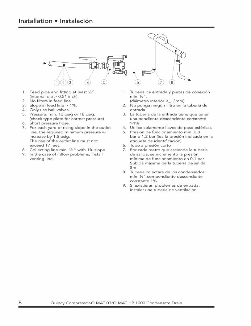
1. Feed pipe and fitting at least ½”. (internal dia > 0,51 inch)2. No filters in feed line 3. Slope in feed line > 1%.4. Only use ball valves.5. Pressure: min. 12 psig or 18 psig. (check type plate for correct pressure)6. Short pressure hose.7. For each yard of rising slope in the outlet
line, the required minimum pressure will increase by 1.5 psig.
The rise of the outlet line must not exceed 17 feet.
8. Collecting line min. ½ ‘’ with 1% slope9. In the case of inflow problems, install
venting line.
1. Tubería de entrada y piezas de conexión mín. ½”.
(diámetro interior <_13mm). 2. No ponga ningún filtro en la tubería de
entrada 3. La tubería de la entrada tiene que tener
una pendiente descendente constante >1%
4. Utilice solamente llaves de paso esféricas5. Presión de funcionamiento mín. 0,8
bar o 1,2 bar (lea la presión indicada en la etiqueta de identificación)
6. Tubo a presión corto7. Por cada metro que asciende la tubería
de salida, se incremento la presión mínima de funcionamiento en 0,1 bar. Subida máxima de la tubería de salida: 5m
8. Tubería colectara de los condensados: mín. ½” con pendiente descendente constante 1%
9. Si existieran problemas de entrada, instalar una tubería de ventilación.
2 3 4 51 6 87
8 Quincy Compressor-Q MAT 03/Q MAT HP 1000 Condensate Drain
Installation • Instalação
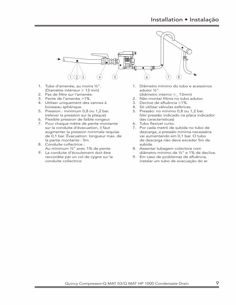
1. Tube d’amenée, au moins ½”. (Diamètre intérieur > 13 mm)2. Pas de filtre sur l’amenée.3. Pente de l’amenée >1%.4. Utiliser uniquement des vannes à boisseau sphérique.5. Pression : minimum 0,8 ou 1,2 bar. (relever la pression sur la plaque)6. Flexible pression de faible rongeur.7. Pour chaque mètre de pente montante
sur la conduite d’évacuation, il faut augmenter la pression minimale requise de 0,1 bar. Évacuation: longueur max. de la partie montante : 5m.
8. Conduite collectrice : Au minimum ½” avec 1% de pente.9. La conduite d’écoulement doit être
raccordée par un col de cygne sur la conduite collectrice
1. Diâmetro mínimo do tubo e acessórios adutor ½”.
(diâmetro interno <_ 13mm)2. Não montar filtros no tubo adutor.3. Declive de afluência >1%.4. Só utilizar válvulas esféricas.5. Pressão: no mínimo 0,8 ou 1,2 bar.
(Ver pressão indicado na placa indicador das características)
6. Tubo flexível curto.7. Por cada metrô de subida no tubo de
descarga, a pressão mínima necessária vai aumentando em 0,1 bar. O tubo de descarga não deve exceder 5m de subida.
8. Assentar tubagem colectora com diâmetro mínimo de ½” e 1% de declive.
9. Em caso de problemas de afluência, instalar um tubo de evacuação do ar.
2 3 4 51 6 87
Quincy Compressor-Q MAT 03/Q MAT HP 1000 Condensate Drain 9
Installation • Instalación
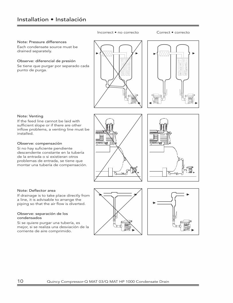
Note: Pressure differencesEach condensate source must be drained separately.
Observe: diferencial de presiónSe tiene que purgar por separado cada punto de purga.
Note: VentingIf the feed line cannot be laid with suffi cient slope or if there are other infl ow problems, a venting line must be installed.
Observe: compensaciónSi no hay sufi ciente pendiente descendente constante en la tubería de la entrada o si existieran otros problemas de entrada, se tiene que montar una tubería de compensación.
Note: Defl ector areaIf drainage is to take place directly from a line, it is advisable to arrange the piping so that the air fl ow is diverted.
Observe: separación de los condensadosSi se quiere purgar una tubería, es mejor, si se realiza una desviación de la corriente de aire comprimido.
Incorrect • no correcto Correct • correcto
10 Quincy Compressor-Q MAT 03/Q MAT HP 1000 Condensate Drain
Installation • Instalação
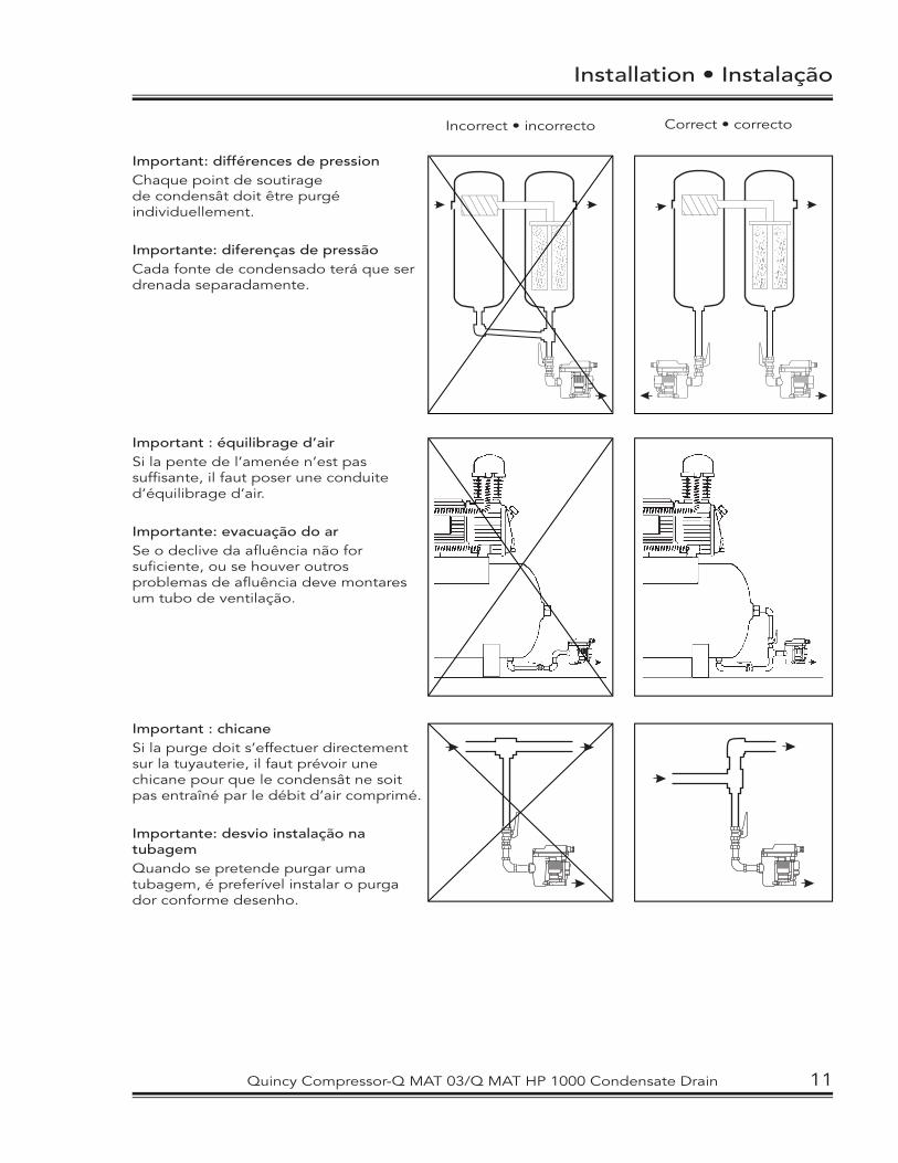
Important: différences de pressionChaque point de soutirage de condensât doit être purgé individuellement.
Importante: diferenças de pressãoCada fonte de condensado terá que ser drenada separadamente.
Important : équilibrage d’airSi la pente de l’amenée n’est pas suffi sante, il faut poser une conduite d’équilibrage d’air.
Importante: evacuação do arSe o declive da afl uência não for sufi ciente, ou se houver outros problemas de afl uência deve montares um tubo de ventilação.
Important : chicaneSi la purge doit s’effectuer directement sur la tuyauterie, il faut prévoir une chicane pour que le condensât ne soit pas entraîné par le débit d’air comprimé.
Importante: desvio instalação na tubagemQuando se pretende purgar uma tubagem, é preferível instalar o purga dor conforme desenho.
Incorrect • incorrecto Correct • correcto
Quincy Compressor-Q MAT 03/Q MAT HP 1000 Condensate Drain 11
Installation • Instalación
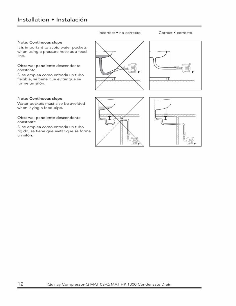
Note: Continuous slopeIt is important to avoid water pockets when using a pressure hose as a feed line.
Observe: pendiente descendente constanteSi se emplea como entrada un tubo fl exible, se tiene que evitar que se forme un sifón.
Note: Continuous slopeWater pockets must also be avoided when laying a feed pipe.
Observe: pendiente descendente constanteSi se emplea como entrada un tubo rígido, se tiene que evitar que se forme un sifón.
Correct • correctoIncorrect • no correcto
12 Quincy Compressor-Q MAT 03/Q MAT HP 1000 Condensate Drain
Installation • Instalação
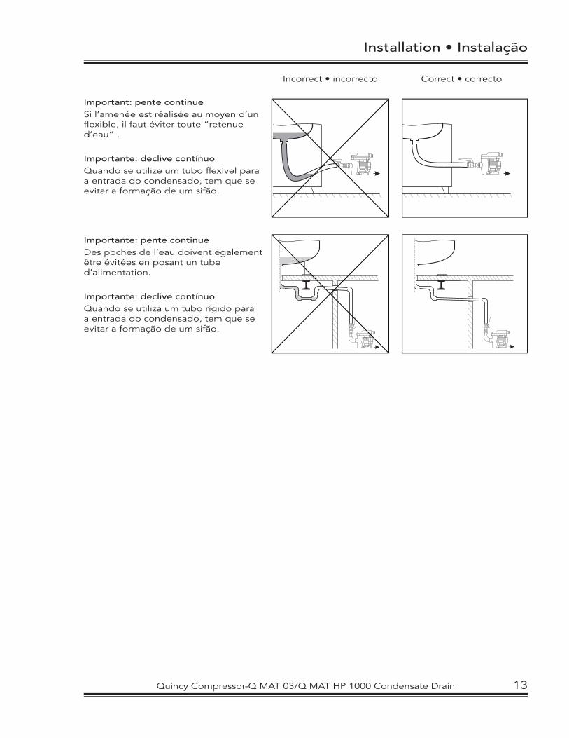
Important: pente continue Si l’amenée est réalisée au moyen d’un fl exible, il faut éviter toute “retenue d’eau” .
Importante: declive contínuoQuando se utilize um tubo fl exível para a entrada do condensado, tem que se evitar a formação de um sifão.
Importante: pente continueDes poches de l’eau doivent également être évitées en posant un tube d’alimentation.
Importante: declive contínuoQuando se utiliza um tubo rígido para a entrada do condensado, tem que se evitar a formação de um sifão.
Incorrect • incorrecto Correct • correcto
Quincy Compressor-Q MAT 03/Q MAT HP 1000 Condensate Drain 13
Electrical Installation
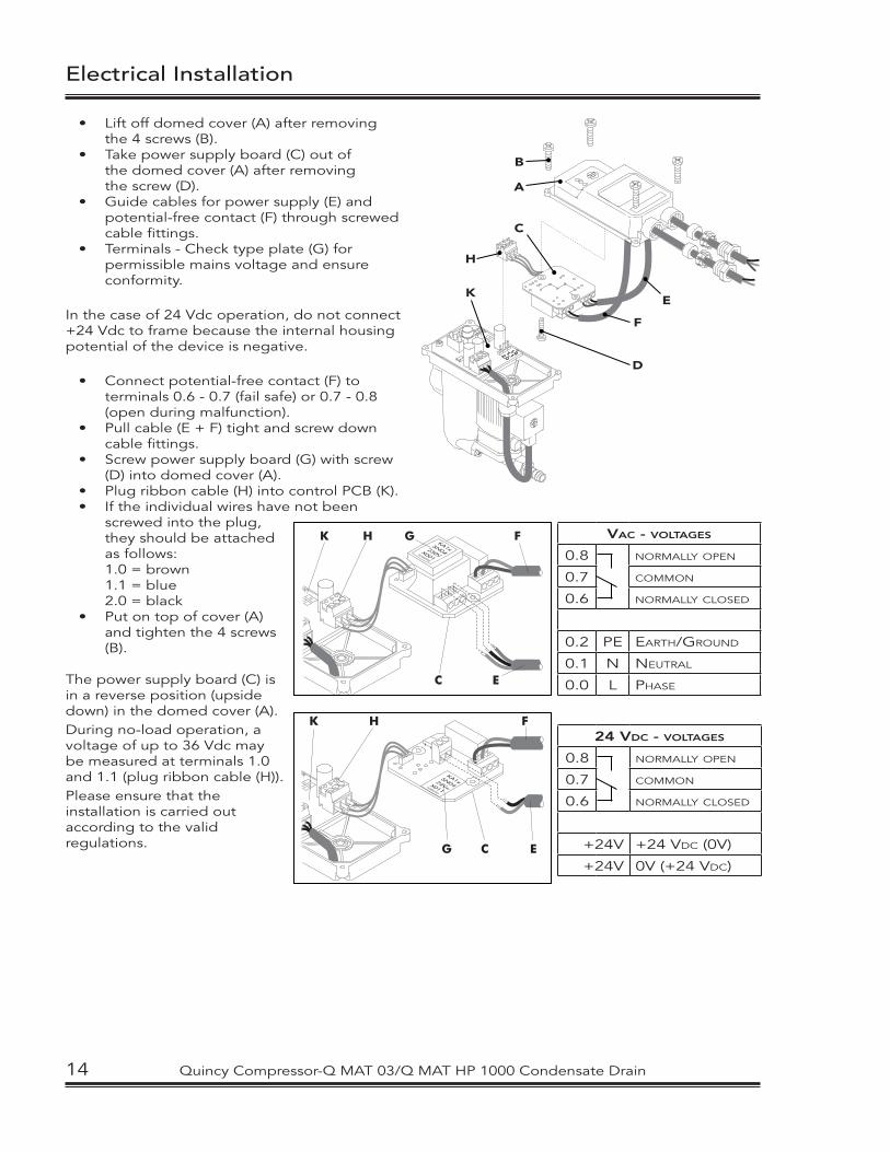
• Lift off domed cover (A) after removing the 4 screws (B).
• Take power supply board (C) out of the domed cover (A) after removing the screw (D).
• Guide cables for power supply (E) and potential-free contact (F) through screwed cable fittings.
• Terminals - Check type plate (G) for permissible mains voltage and ensure conformity.
In the case of 24 Vdc operation, do not connect +24 Vdc to frame because the internal housing potential of the device is negative.
• Connect potential-free contact (F) to terminals 0.6 - 0.7 (fail safe) or 0.7 - 0.8 (open during malfunction).
• Pull cable (E + F) tight and screw down cable fittings.
• Screw power supply board (G) with screw (D) into domed cover (A).
• Plug ribbon cable (H) into control PCB (K).• If the individual wires have not been
screwed into the plug, they should be attached as follows:
1.0 = brown 1.1 = blue 2.0 = black• Put on top of cover (A)
and tighten the 4 screws (B).
The power supply board (C) is in a reverse position (upside down) in the domed cover (A). During no-load operation, a voltage of up to 36 Vdc may be measured at terminals 1.0 and 1.1 (plug ribbon cable (H)).Please ensure that the installation is carried out according to the valid regulations.
1 . 02 . 01 . 1
B
A
C
H
K
D
F
E
K H G F
C E
VAC - VOLTAGES
0.8 NORMALLY OPEN
0.7 COMMON
0.6 NORMALLY CLOSED
0.2 PE EARTH/GROUND
0.1 N NEUTRAL
0.0 L PHASE
K H F
G C E
24 VDC - VOLTAGES
0.8 NORMALLY OPEN
0.7 COMMON
0.6 NORMALLY CLOSED
+24V +24 VDC (0V)
+24V 0V (+24 VDC)
14 Quincy Compressor-Q MAT 03/Q MAT HP 1000 Condensate Drain

Instalación Eléctrica
1 . 02 . 01 . 1
B
A
C
H
K
D
F
E
• desmonte la tapa (A) superior (4 tornillos (B))
• desmonte el circuito impreso de la fuente de alimentación de la tapa (A)
superior (1 tornillo (B)• guie los cables a través de las tuer cas
correspondientes• Bornes - Verifique la tensión admisible en
la etiqueta de identificación (G).
En caso de servicio con 24 Vdcno se deberá conectar la masa + (plus) 24 Vdc, puesto que en el interior del aparato el negativo está conectado al potencial de carcasa.
• conecte los contactos libres de potencial (F) a los bornes 0.6 - 0.7 (en alarma cerrado) o 0.7 - 0.8 (en alarma abierto)
• tense el cable y fijelo con los tornillos correspondientes
• monte el circuito impreso de la fuente de alimentación
• conecte el conectar de cable plano en el circuito de pilotaje
• Si los cables aislados fueron desatornillados erròneamente del conectar, es vàlida la siguiente asignaciòn:
1.0 = marròn 1.1 = azul 2.0 = negro
El circuito impreso de la fuente de alimentación está girado hacia abajo y fijado dentro de la tapa superior.En el funcionamiento sin carga se puede medir una tensión de hasta 36 Vcc entre los bornes 1.0 y 1.1.Ejecute la instalación eléctrica según las normas vigentes.
K H G F
C E
VAC - VOLTAGES
0.8 NORMALLY OPEN
0.7 COMMON
0.6 NORMALLY CLOSED
0.2 PE EARTH/GROUND
0.1 N NEUTRAL
0.0 L PHASE
K H F
G C E
24 VDC - VOLTAGES
0.8 NORMALLY OPEN
0.7 COMMON
0.6 NORMALLY CLOSED
+24V +24 VDC (0V)
+24V 0V (+24 VDC)
Quincy Compressor-Q MAT 03/Q MAT HP 1000 Condensate Drain 15
1 . 02 . 01 . 1
B
A
C
H
K
D
F
E
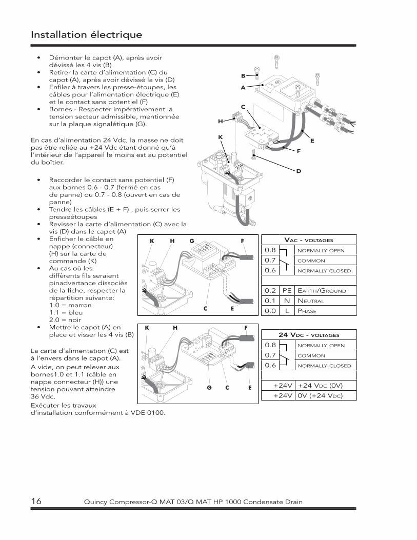
• Démonter le capot (A), après avoir dévissé les 4 vis (B)• Retirer la carte d’alimentation (C) du
capot (A), après avoir dévissé la vis (D)• Enfiler à travers les presse-étoupes, les
câbles pour l’alimentation électrique (E) et le contact sans potentiel (F)
• Bornes - Respecter impérativement la tension secteur admissible, mentionnée sur la plaque signalétique (G).
En cas d’alimentation 24 Vdc, la masse ne doit pas être reliée au +24 Vdc étant donné qu’à l’intérieur de l’appareil le moins est au potentiel du boîtier.
• Raccorder le contact sans potentiel (F) aux bornes 0.6 - 0.7 (fermé en cas de panne) ou 0.7 - 0.8 (ouvert en cas de panne)
• Tendre les câbles (E + F) , puis serrer les presseétoupes
• Revisser la carte d’alimentation (C) avec la vis (D) dans le capot (A)
• Enficher le câble en nappe (connecteur) (H) sur la carte de commande (K)
• Au cas où les diffèrents fils seraient pinadvertance dissociès de la fiche, respecter la rèpartition suivante: 1.0 = marron
1.1 = bleu 2.0 = noir • Mettre le capot (A) en
place et visser les 4 vis (B)
La carte d’alimentation (C) est à l’envers dans le capot (A).A vide, on peut relever aux bornes1.0 et 1.1 (câble en nappe connecteur (H)) une tension pouvant atteindre 36 Vdc.Exécuter les travaux d’installation conformément à VDE 0100.
Installation électrique
K H G F
C E
VAC - VOLTAGES
0.8 NORMALLY OPEN
0.7 COMMON
0.6 NORMALLY CLOSED
0.2 PE EARTH/GROUND
0.1 N NEUTRAL
0.0 L PHASE
K H F
G C E
24 VDC - VOLTAGES
0.8 NORMALLY OPEN
0.7 COMMON
0.6 NORMALLY CLOSED
+24V +24 VDC (0V)
+24V 0V (+24 VDC)
16 Quincy Compressor-Q MAT 03/Q MAT HP 1000 Condensate Drain
Instalação Eléctrica
1 . 02 . 01 . 1
B
A
C
H
K
D
F
E
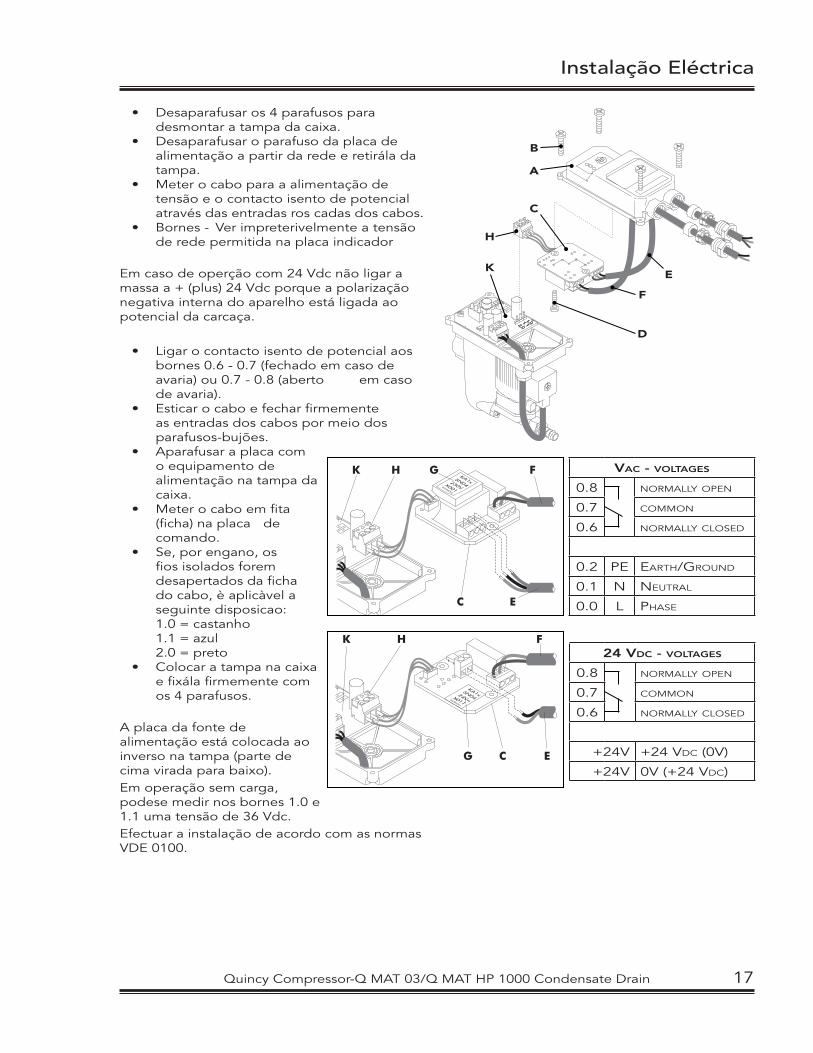
• Desaparafusar os 4 parafusos para desmontar a tampa da caixa.
• Desaparafusar o parafuso da placa de alimentação a partir da rede e retirála da tampa.
• Meter o cabo para a alimentação de tensão e o contacto isento de potencial através das entradas ros cadas dos cabos.
• Bornes - Ver impreterivelmente a tensão de rede permitida na placa indicador
Em caso de operção com 24 Vdc não ligar a massa a + (plus) 24 Vdc porque a polarização negativa interna do aparelho está ligada ao potencial da carcaça.
• Ligar o contacto isento de potencial aos bornes 0.6 - 0.7 (fechado em caso de avaria) ou 0.7 - 0.8 (aberto em caso de avaria).
• Esticar o cabo e fechar firmemente as entradas dos cabos por meio dos parafusos-bujões.
• Aparafusar a placa com o equipamento de alimentação na tampa da caixa.
• Meter o cabo em fita (ficha) na placa de comando.
• Se, por engano, os fios isolados forem desapertados da ficha do cabo, è aplicàvel a seguinte disposicao:
1.0 = castanho 1.1 = azul 2.0 = preto• Colocar a tampa na caixa
e fixála firmemente com os 4 parafusos.
A placa da fonte de alimentação está colocada ao inverso na tampa (parte de cima virada para baixo).Em operação sem carga, podese medir nos bornes 1.0 e 1.1 uma tensão de 36 Vdc.Efectuar a instalação de acordo com as normas VDE 0100.
K H G F
C E
VAC - VOLTAGES
0.8 NORMALLY OPEN
0.7 COMMON
0.6 NORMALLY CLOSED
0.2 PE EARTH/GROUND
0.1 N NEUTRAL
0.0 L PHASE
K H F
G C E
24 VDC - VOLTAGES
0.8 NORMALLY OPEN
0.7 COMMON
0.6 NORMALLY CLOSED
+24V +24 VDC (0V)
+24V 0V (+24 VDC)
Quincy Compressor-Q MAT 03/Q MAT HP 1000 Condensate Drain 17
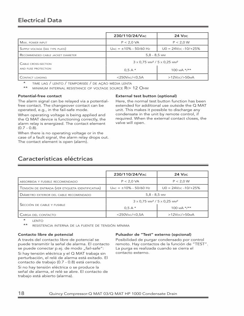
230/110/24/VAC 24 VDC
MAX. POWER INPUT P < 2,0 VA P < 2,0 W
SUPPLY VOLTAGE (SEE TYPE PLATE) UAC = ±10% - 50/60 HZ U0 = 24VDC -10/+25%
RECOMMENDED CABLE JACKET DIAMETER 5,8 - 8,5 MM
CABLE CROSS-SECTION
AND FUSE PROTECTION
3 X 0,75 MM² / 5 X 0,25 MM²
0,5 A * 100 MA */**
CONTACT LOADING <250VAC/<0,5A >12VDC/>50MA
* TIME LAG / LENTO / TEMPORISÉE / DE AÇÃO MÉDIA LENTA
** MINIMUM INTERNAL RESISTANCE OF VOLTAGE SOURCE RI> 12 OHM
Electrical Data
Caracteristicas eléctricas
Potential-free contactThe alarm signal can be relayed via a potential-free contact. The changeover contact can be operated, e.g., in the fail-safe mode. When operating voltage is being applied and the Q MAT device is functioning correctly, the alarm relay is energized. The contact element (0.7 - 0.8).When there is no operating voltage or in the case of a fault signal, the alarm relay drops out. The contact element is open (alarm).
External test button (optional)Here, the normal test button function has been extended for additional use outside the Q MAT unit. This makes it possible to discharge any condensate in the unit by remote control, if required. When the external contact closes, the valve will open.
230/110/24/VAC 24 VDC
ABSORBIDA Y FUSIBLE RECOMENDADO P < 2,0 VA P < 2,0 W
TENSIÓN DE ENTRADA (VER ETIQUETA IDENTIFICATIVA) UAC = ±10% - 50/60 HZ U0 = 24VDC -10/+25%
DIÁMETRO EXTERIOR DEL CABLE RECOMENDADO 5,8 - 8,5 MM
SECCIÓN DE CABLE Y FUSIBLE3 X 0,75 MM² / 5 X 0,25 MM²
0,5 A * 100 MA */**
CARGA DEL CONTACTO <250VAC/<0,5A >12VDC/>50MA
* LENTO
** RESISTENCIA INTERNA DE LA FUENTE DE TENSIÓN MÍNIMA
Contacto libre de potencialA través del contacto libre de potencial se puede transmitir la señal de alarma. El contacto se puede conectar p.ej. de modo „fail-safe“: Si hay tensión eléctrica y el Q MAT trabaja sin perturbación, el relé de alarma está exitado. El contacto de trabajo (0.7 - 0.8) está cerrado. Si no hay tensión eléctrica o se produce la señal de alarma, el relé se abre. El contacto de trabajo está abierto (alarma).
Pulsador de “Test” externo (opcional) Posibilidad de purgar condensado por control remoto. Hay contactos de la función de ”TEST”. La purga es realizada cuando se cierra el contacto externo.
18 Quincy Compressor-Q MAT 03/Q MAT HP 1000 Condensate Drain
Charactéristiques electrique
Dados eléctricos
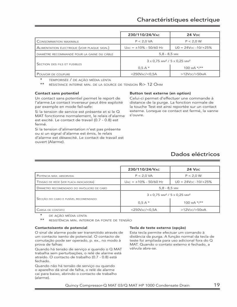
230/110/24/VAC 24 VDC
CONSOMMATION MAXIMALE P < 2,0 VA P < 2,0 W
ALIMENTATION ÉLECTRIQUE (VOIR PLAQUE SIGN.) UAC = ±10% - 50/60 HZ U0 = 24VDC -10/+25%
DIAMÈTRE RECOMMANDÉ POUR LA GAINE DU CÂBLE 5,8 - 8,5 MM
SECTION DES FILS ET FUSIBLES3 X 0,75 MM² / 5 X 0,25 MM²
0,5 A * 100 MA */**
POUVOIR DE COUPURE <250VAC/<0,5A >12VDC/>50MA
* TEMPORISÉE / DE AÇÃO MÉDIA LENTA
** RÉSISTANCE INTERNE MIN. DE LA SOURCE DE TENSION RI> 12 OHM
Contact sans potentielUn contact sans potentiel permet le report de l’alarme.Le contact inverseur peut être exploité par exemple en mode fail-safe: Si la tension de service est présente et si le Q MAT fonctionne normalement, le relais d’alarme est excité. Le contact de travail (0.7 - 0.8) est fermé.Si la tension d’alimentation n’est pas présente ou si un signal d’alarme est émis, le relais d’alarme est désexcité. Le contact de travail est ouvert (Alarme).
Button test externe (en option)Celui-ci permet d’effectuer une commande à distance de la purge. La fonction normale de la touche Test est ainsi reportée sur un contact externe. Lorsque ce contact est fermé, la vanne s’ouvre.
230/110/24/VAC 24 VDC
POTÊNCIA MÁX. ABSORVIDA P < 2,0 VA P < 2,0 W
TENSÃO DE REDE (VER PLACA INDICADORA) UAC = ±10% - 50/60 HZ U0 = 24VDC -10/+25%
DIÂMETRO RECOMENDADO DO INVÓLUCRO DE CABO 5,8 - 8,5 MM
SECÇÃO DO CABO E FUSÍVEL RECOMENDADO
3 X 0,75 MM² / 5 X 0,25 MM²
0,5 A * 100 MA */**
CARGA DE CONTATO <250VAC/<0,5A >12VDC/>50MA
* DE AÇÃO MÉDIA LENTA
** RESISTÊNCIA MIN. INTERIOR DA FONTE DE TENSÃO
Contactoisento de potencialO sinal de alarme pode ser transmitido através de um contacto isento de potencial. O contacto de comutação pode ser operado, p. ex., no modo à prova de falhas:Quando há tensão de serviço e quando o Q MAT trabalha sem perturbações, o relé de alarme está atraído. O contacto de trabalho (0.7 - 0.8) está fechado.Quando não há tensão de serviço ou quando o aparelho dá sinal de falha, o relé de alarme cai para baixo, abrindo o contacto de trabalho (alarme).
Tecla de teste externo (opção) Esta tecla permite efectuar um comando à distância da purga. A função normal da tecla de teste foi ampliada para uso adicional fora do Q MAT. Quando o contato externo é fechado, a válvula abre-se.
Quincy Compressor-Q MAT 03/Q MAT HP 1000 Condensate Drain 19
Maintenance
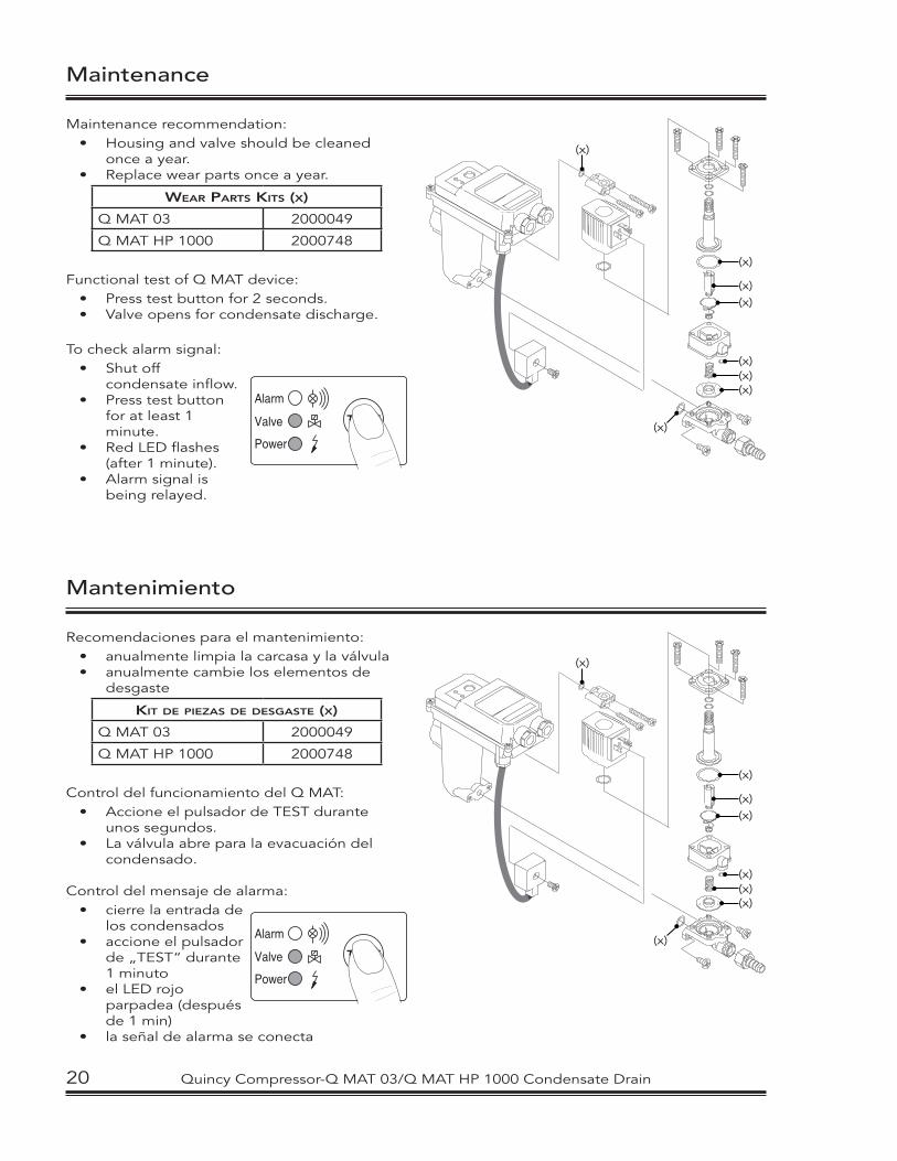
Maintenance recommendation:• Housing and valve should be cleaned
once a year.• Replace wear parts once a year.
WEAR PARTS KITS (X)
Q MAT 03 2000049
Q MAT HP 1000 2000748
Functional test of Q MAT device:• Press test button for 2 seconds.• Valve opens for condensate discharge.
To check alarm signal:• Shut off
condensate inflow.• Press test button
for at least 1 minute.
• Red LED flashes (after 1 minute).
• Alarm signal is being relayed.
TEST
Power
Alarm
Valve
(x)
(x)(x)
(x)(x)(x)
(x)
(x)
Mantenimiento
(x)
(x)(x)
(x)(x)(x)
(x)
(x)
Recomendaciones para el mantenimiento:• anualmente limpia la carcasa y la válvula• anualmente cambie los elementos de
desgaste
KIT DE PIEZAS DE DESGASTE (X)
Q MAT 03 2000049
Q MAT HP 1000 2000748
Control del funcionamiento del Q MAT:• Accione el pulsador de TEST durante
unos segundos.• La válvula abre para la evacuación del
condensado.
Control del mensaje de alarma:• cierre la entrada de
los condensados• accione el pulsador
de „TEST“ durante 1 minuto
• el LED rojo parpadea (después de 1 min)
• la señal de alarma se conecta
TEST
Power
Alarm
Valve
20 Quincy Compressor-Q MAT 03/Q MAT HP 1000 Condensate Drain
Entretien
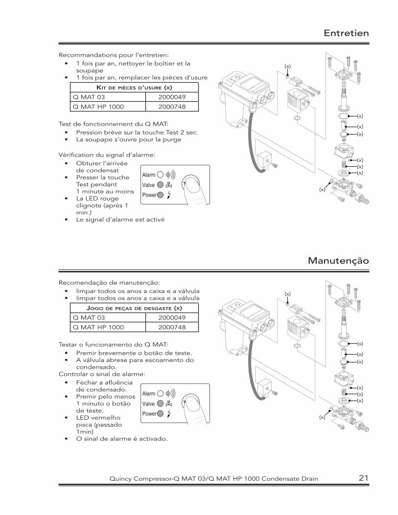
Recommandations pour l’entretien: • 1 fois par an, nettoyer le boîtier et la
soupape• 1 fois par an, remplacer les pièces d’usure
KIT DE PIÈCES D’USURE (X)
Q MAT 03 2000049
Q MAT HP 1000 2000748
Test de fonctionnement du Q MAT:• Pression brève sur la touche Test 2 sec.• La soupape s’ouvre pour la purge
Vérification du signal d’alarme:• Obturer l’arrivée
de condensat• Presser la touche
Test pendant 1 minute au moins• La LED rouge
clignote (après 1 min.)
• Le signal d’alarme est activé
TEST
Power
Alarm
Valve
(x)
(x)(x)
(x)(x)(x)
(x)
(x)
Manutenção
(x)
(x)(x)
(x)(x)(x)
(x)
(x)
Recomendação de manutenção:• limpar todos os anos a caixa e a válvula• limpar todos os anos a caixa e a válvula
JOGO DE PEÇAS DE DESGASTE (X)
Q MAT 03 2000049
Q MAT HP 1000 2000748
Testar o funcionamento do Q MAT:• Premir brevemente o botão de teste.• A válvula abrese para escoamento do
condensado.Controlar o sinal de alarme:
• Fechar a afluência de condensado.
• Premir pelo menos 1 minuto o botão de teste.
• LED vermelho pisca (passado 1min)
• O sinal de alarme é activado.
TEST
Power
Alarm
Valve
Quincy Compressor-Q MAT 03/Q MAT HP 1000 Condensate Drain 21
LED NOT LIGHTING UP:
NO CONDENSATE DISCHARGE WHEN TEST BUTTON IS PRESSED:
CONDENSATE DISCHARGE ONLY WHEN TEST BUTTON IS PRESSED:
DEVICE KEEPS BLOWING OFF AIR:
Troubleshooting
POSSIBLE CAUSES:
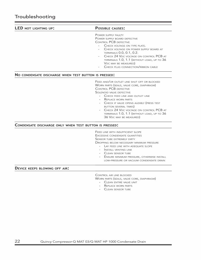
POWER SUPPLY FAULTY
POWER SUPPLY BOARD DEFECTIVE
CONTROL PCB DEFECTIVE
- CHECK VOLTAGE ON TYPE PLATE.- CHECK VOLTAGE ON POWER SUPPLY BOARD AT
TERMINALS 0.0, 0.1, 0.2.- CHECK 24 VDC VOLTAGE ON CONTROL PCB AT
TERMINALS 1.0, 1.1 (WITHOUT LOAD, UP TO 36 VDC MAY BE MEASURED)
- CHECK PLUG CONNECTION/RIBBON CABLE
FEED AND/OR OUTLET LINE SHUT OFF OR BLOCKED
WORN PARTS (SEALS, VALVE CORE, DIAPHRAGM)CONTROL PCB DEFECTIVE
SOLENOID VALVE DEFECTIVE
- CHECK FEED LINE AND OUTLET LINE
- REPLACE WORN PARTS
- CHECK IF VALVE OPENS AUDIBLY (PRESS TEST BUTTON SEVERAL TIMES)
- CHECK 24 VDC VOLTAGE ON CONTROL PCB AT TERMINALS 1.0, 1.1 (WITHOUT LOAD, UP TO 36 36 VDC MAY BE MEASURED)
FEED LINE WITH INSUFFICIENT SLOPE
EXCESSIVE CONDENSATE QUANTITIES
SENSOR TUBE EXTREMELY DIRTY
DROPPING BELOW NECESSARY MINIMUM PRESSURE
- LAY FEED LINE WITH ADEQUATE SLOPE
- INSTALL VENTING LINE
- CLEAN SENSOR TUBE
- ENSURE MINIMUM PRESSURE, OTHERWISE INSTALL LOW-PRESSURE OR VACUUM CONDENSATE DRAIN
CONTROL AIR LINE BLOCKED
WORN PARTS (SEALS, VALVE CORE, DIAPHRAGM) - CLEAN ENTIRE VALVE UNIT
- REPLACE WORN PARTS
- CLEAN SENSOR TUBE
22 Quincy Compressor-Q MAT 03/Q MAT HP 1000 Condensate Drain
NINGÚN LED ESTÁ ILUMINADO:
EL INTERRUPTOR DE „TEST“ ESTÁ PULSADO, PERO EL CONDENSADO NO SE EVACUA:
EVACUACIÓN DEL CONDENSADO SOLO SI ESTÁ PULSADO EL INTERRUPTOR DE „TEST“:
EL APARATO ESTÁ ABIERTO CONSTANTEMENTE:
Búsqueda de fallos
POSIBLES CAUSAS:
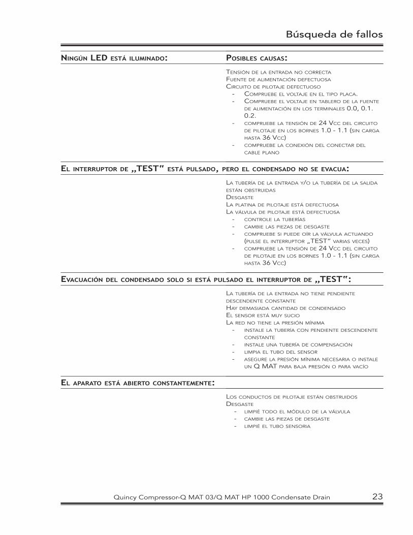
TENSIÓN DE LA ENTRADA NO CORRECTA
FUENTE DE ALIMENTACIÓN DEFECTUOSA
CIRCUITO DE PILOTAJE DEFECTUOSO
- COMPRUEBE EL VOLTAJE EN EL TIPO PLACA.- COMPRUEBE EL VOLTAJE EN TABLERO DE LA FUENTE
DE ALIMENTACIÓN EN LOS TERMINALES 0.0, 0.1. 0.2.
- COMPRUEBE LA TENSIÓN DE 24 VCC DEL CIRCUITO DE PILOTAJE EN LOS BORNES 1.0 - 1.1 (SIN CARGA HASTA 36 VCC)
- COMPRUEBE LA CONEXIÓN DEL CONECTAR DEL CABLE PLANO
LA TUBERÍA DE LA ENTRADA Y/O LA TUBERÍA DE LA SALIDA ESTÁN OBSTRUIDAS
DESGASTE
LA PLATINA DE PILOTAJE ESTÁ DEFECTUOSA
LA VÁLVULA DE PILOTAJE ESTÁ DEFECTUOSA
- CONTROLE LA TUBERÍAS
- CAMBIE LAS PIEZAS DE DESGASTE
- COMPRUEBE SI PUEDE OÍR LA VÁLVULA ACTUANDO (PULSE EL INTERRUPTOR „TEST“ VARIAS VECES)
- COMPRUEBE LA TENSIÓN DE 24 VCC DEL CIRCUITO DE PILOTAJE EN LOS BORNES 1.0 - 1.1 (SIN CARGA HASTA 36 VCC)
LA TUBERÍA DE LA ENTRADA NO TIENE PENDIENTE DESCENDENTE CONSTANTE
HAY DEMASIADA CANTIDAD DE CONDENSADO
EL SENSOR ESTÁ MUY SUCIO
LA RED NO TIENE LA PRESIÓN MÍNIMA - INSTALE LA TUBERÍA CON PENDIENTE DESCENDENTE
CONSTANTE
- INSTALE UNA TUBERÍA DE COMPENSACIÓN
- LIMPIA EL TUBO DEL SENSOR
- ASEGURE LA PRESIÓN MÍNIMA NECESARIA O INSTALE UN Q MAT PARA BAJA PRESIÓN O PARA VACÍO
LOS CONDUCTOS DE PILOTAJE ESTÁN OBSTRUIDOS
DESGASTE
- LIMPIÉ TODO EL MÓDULO DE LA VÁLVULA
- CAMBIE LAS PIEZAS DE DESGASTE
- LIMPIÉ EL TUBO SENSORIA
Quincy Compressor-Q MAT 03/Q MAT HP 1000 Condensate Drain 23
AUCUNE LED N’EST ALLUMÉE:
LA TOUCHE TEST EST ACTIONNÉE, MAIS SANS PURGE DU CONDENSÂT:
PURGE DU CONDENSÂT UNIQUEMENT SI LA TOUCHE TEST EST ACTIONNÉE:
L’APPAREIL REFOULE DE L’AIR EN PERMANENCE:
Recherche de panne
ORIGINES POSSIBLES:
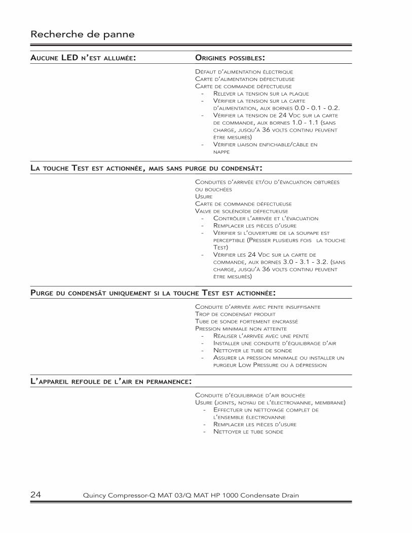
DÉFAUT D’ALIMENTATION ÉLECTRIQUE
CARTE D’ALIMENTATION DÉFECTUEUSE
CARTE DE COMMANDE DÉFECTUEUSE
- RELEVER LA TENSION SUR LA PLAQUE
- VÉRIFIER LA TENSION SUR LA CARTE D’ALIMENTATION, AUX BORNES 0.0 - 0.1 - 0.2.
- VÉRIFIER LA TENSION DE 24 VDC SUR LA CARTE DE COMMANDE, AUX BORNES 1.0 - 1.1 (SANS CHARGE, JUSQU’À 36 VOLTS CONTINU PEUVENT ÊTRE MESURÉS)
- VÉRIFIER LIAISON ENFICHABLE/CÂBLE EN NAPPE
CONDUITES D’ARRIVÉE ET/OU D’ÉVACUATION OBTURÉES OU BOUCHÉES
USURE
CARTE DE COMMANDE DÉFECTUEUSE
VALVE DE SOLÉNOÏDE DÉFECTUEUSE
- CONTRÔLER L’ARRIVÉE ET L’ÉVACUATION
- REMPLACER LES PIÈCES D’USURE
- VÉRIFIER SI L’OUVERTURE DE LA SOUPAPE EST PERCEPTIBLE (PRESSER PLUSIEURS FOIS LA TOUCHE TEST)
- VÉRIFIER LES 24 VDC SUR LA CARTE DE COMMANDE, AUX BORNES 3.0 - 3.1 - 3.2. (SANS CHARGE, JUSQU’À 36 VOLTS CONTINU PEUVENT ÊTRE MESURÉS)
CONDUITE D’ARRIVÉE AVEC PENTE INSUFFISANTE
TROP DE CONDENSAT PRODUIT
TUBE DE SONDE FORTEMENT ENCRASSÉ
PRESSION MINIMALE NON ATTEINTE
- RÉALISER L’ARRIVÉE AVEC UNE PENTE
- INSTALLER UNE CONDUITE D’ÉQUILIBRAGE D’AIR
- NETTOYER LE TUBE DE SONDE
- ASSURER LA PRESSION MINIMALE OU INSTALLER UN PURGEUR LOW PRESSURE OU À DÉPRESSION
CONDUITE D’ÉQUILIBRAGE D’AIR BOUCHÉE
USURE (JOINTS, NOYAU DE L’ÉLECTROVANNE, MEMBRANE) - EFFECTUER UN NETTOYAGE COMPLET DE
L’ENSEMBLE ÉLECTROVANNE
- REMPLACER LES PIÈCES D’USURE
- NETTOYER LE TUBE SONDE
24 Quincy Compressor-Q MAT 03/Q MAT HP 1000 Condensate Drain
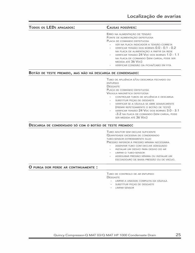
Localização de avarias
TODOS OS LEDS APAGADOS:
BOTÃO DE TESTE PREMIDO, MAS NÃO HÁ DESCARGA DE CONDENSADO:
DESCARGA DE CONDENSADO SÓ COM O BOTÃO DE TESTE PREMIDO:
O PURGA DOR PERDE AR CONTINUAMENTE :
CAUSAS POSSÍVEIS:
ERRO NA ALIMENTAÇÃO DE TENSÃO
FONTE DE ALIMENTAÇÃO DEFEITUOSA
PLACA DE COMANDO DEFEITUOSA
- VER NA PLACA INDICADOR A TENSÃO CORRETA
- VERIFICAR TENSÃO DOS BORNES 0.0 - 0.1 - 0.2 NA PLACA DE ALIMENTAÇÃO A PARTIR DA REDE
- VERIFICAR TENSÃO 24 VDC DOS BORNES 1.0 - 1.1 NA PLACA DE COMANDO (SEM CARGA, PODE SER MEDIDA ATÉ 36 VDC)
- VERIFICAR CONEXÃO DA FICHA/CABO EM FITA
TUBO DE AFLUÊNCIA E/OU DESCARGA FECHADO OU ENTUPIDO
DESGASTE
PLACA DE COMANDO DEFEITUOSA
VÁLVULA MAGNÉTICA DEFEITUOSA
- CONTROLAR TUBOS DE AFLUÊNCIA E DESCARGA
- SUBSTITUIR PEÇAS DE DESGASTE
- VERIFICAR SE A VÁLVULA SE ABRE ADIAVELMENTE (PREMIR REPETIDAMENTE O BOTÃO DE TESTE)
- VERIFICAR TENSÃO 24 VDC DOS BORNES 3.0 - 3.1 -3.2 NA PLACA DE COMANDO (SEM CARGA, PODE SER MEDIDA ATÉ 36 VDC)
TUBO ADUTOR SEM DECLIVE SUFICIENTE
QUANTIDADE EXCESSIVA DE CONDENSADO
TUBO-SENSOR EXTREMAMENTE SUJO
PRESSÃO INFERIOR À PRESSÃO MÍNIMA NECESSÁRIA
- ASSENTAR TUBO COM DECLIVE ADEQUADO
- INSTALAR UM DESVIO PARA DESVIO DO AR
- LIMPAR O TUBO-SENSOR
- ASSEGURAR PRESSÃO MÍNIMA OU INSTALAR UM ESCOADOURO DE BAIXA PRESSÃO OU DE VÁCUO.
TUBO DE CONTROLO DE AR ENTUPIDO
DESGASTE - LIMPAR A UNIDADE COMPLETA DA VÁLVULA
- SUBSTITUIR PEÇAS DE DESGASTE
- LIMPAR SENSOR
Quincy Compressor-Q MAT 03/Q MAT HP 1000 Condensate Drain 25
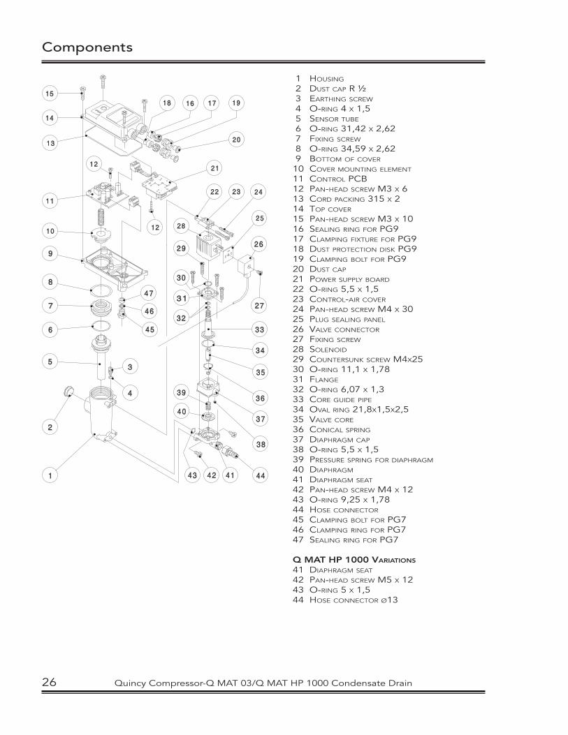
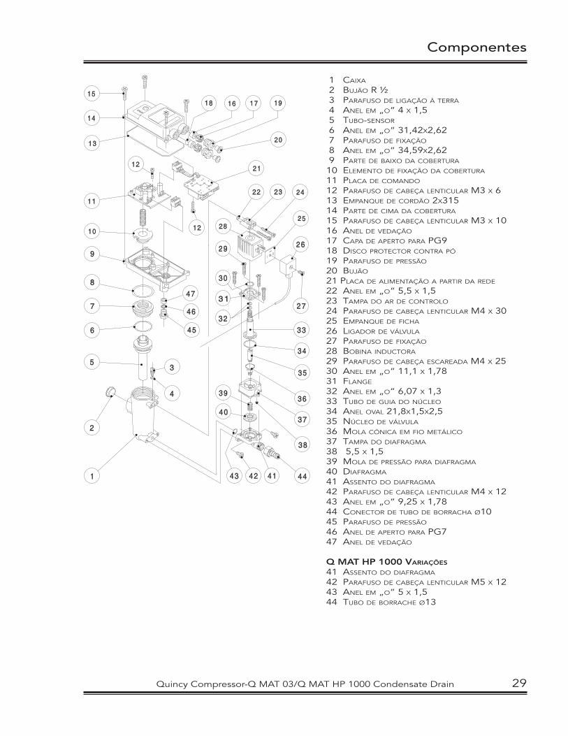
Components
1 HOUSING
2 DUST CAP R ½ 3 EARTHING SCREW
4 O-RING 4 X 1,5 5 SENSOR TUBE
6 O-RING 31,42 X 2,62 7 FIXING SCREW
8 O-RING 34,59 X 2,62 9 BOTTOM OF COVER
10 COVER MOUNTING ELEMENT
11 CONTROL PCB 12 PAN-HEAD SCREW M3 X 613 CORD PACKING 315 X 2 14 TOP COVER
15 PAN-HEAD SCREW M3 X 1016 SEALING RING FOR PG917 CLAMPING FIXTURE FOR PG918 DUST PROTECTION DISK PG919 CLAMPING BOLT FOR PG920 DUST CAP
21 POWER SUPPLY BOARD
22 O-RING 5,5 X 1,523 CONTROL-AIR COVER
24 PAN-HEAD SCREW M4 X 3025 PLUG SEALING PANEL
26 VALVE CONNECTOR
27 FIXING SCREW
28 SOLENOID
29 COUNTERSUNK SCREW M4X2530 O-RING 11,1 X 1,78 31 FLANGE 32 O-RING 6,07 X 1,333 CORE GUIDE PIPE
34 OVAL RING 21,8X1,5X2,535 VALVE CORE 36 CONICAL SPRING
37 DIAPHRAGM CAP
38 O-RING 5,5 X 1,539 PRESSURE SPRING FOR DIAPHRAGM
40 DIAPHRAGM 41 DIAPHRAGM SEAT
42 PAN-HEAD SCREW M4 X 1243 O-RING 9,25 X 1,7844 HOSE CONNECTOR 45 CLAMPING BOLT FOR PG746 CLAMPING RING FOR PG747 SEALING RING FOR PG7
Q MAT HP 1000 VARIATIONS
41 DIAPHRAGM SEAT
42 PAN-HEAD SCREW M5 X 1243 O-RING 5 X 1,544 HOSE CONNECTOR Ø13
26 Quincy Compressor-Q MAT 03/Q MAT HP 1000 Condensate Drain
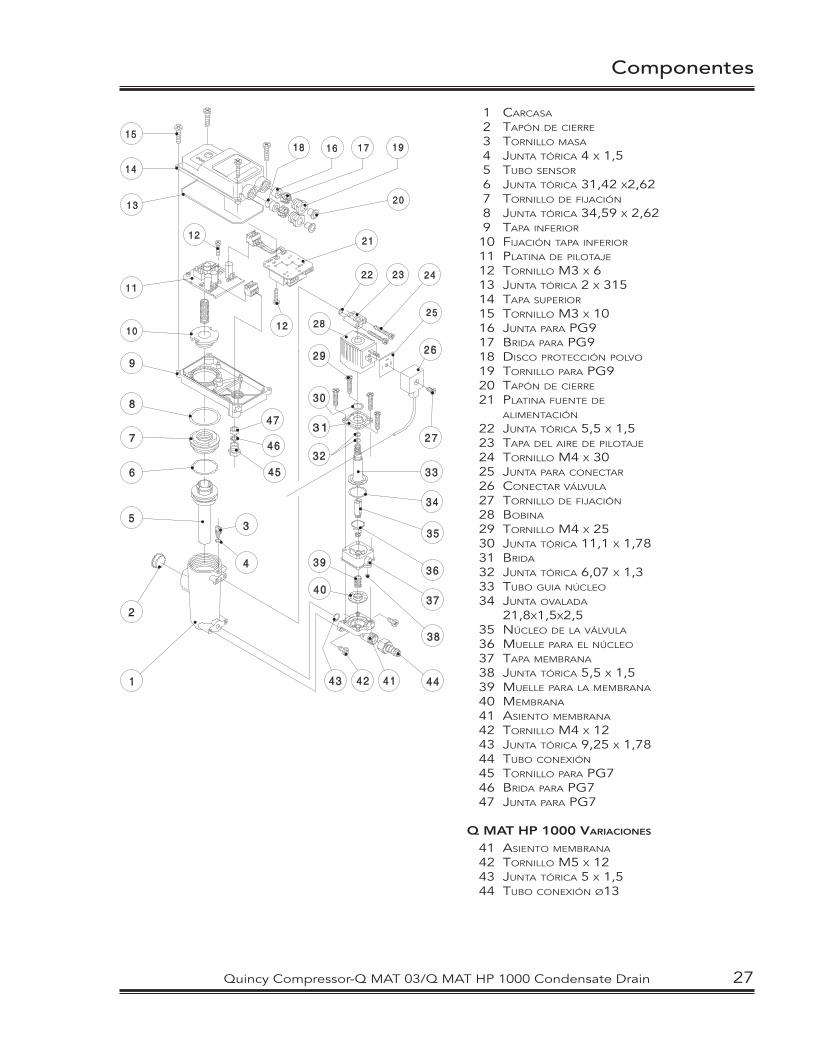
Componentes
1 CARCASA
2 TAPÓN DE CIERRE
3 TORNILLO MASA
4 JUNTA TÓRICA 4 X 1,5 5 TUBO SENSOR
6 JUNTA TÓRICA 31,42 X2,62 7 TORNILLO DE FIJACIÓN
8 JUNTA TÓRICA 34,59 X 2,62 9 TAPA INFERIOR
10 FIJACIÓN TAPA INFERIOR
11 PLATINA DE PILOTAJE 12 TORNILLO M3 X 6 13 JUNTA TÓRICA 2 X 31514 TAPA SUPERIOR 15 TORNILLO M3 X 1016 JUNTA PARA PG9 17 BRIDA PARA PG9 18 DISCO PROTECCIÓN POLVO
19 TORNILLO PARA PG9 20 TAPÓN DE CIERRE
21 PLATINA FUENTE DE ALIMENTACIÓN
22 JUNTA TÓRICA 5,5 X 1,523 TAPA DEL AIRE DE PILOTAJE
24 TORNILLO M4 X 30 25 JUNTA PARA CONECTAR
26 CONECTAR VÁLVULA 27 TORNILLO DE FIJACIÓN
28 BOBINA 29 TORNILLO M4 X 25 30 JUNTA TÓRICA 11,1 X 1,7831 BRIDA
32 JUNTA TÓRICA 6,07 X 1,333 TUBO GUIA NÚCLEO
34 JUNTA OVALADA 21,8X1,5X2,5
35 NÚCLEO DE LA VÁLVULA
36 MUELLE PARA EL NÚCLEO
37 TAPA MEMBRANA
38 JUNTA TÓRICA 5,5 X 1,539 MUELLE PARA LA MEMBRANA
40 MEMBRANA
41 ASIENTO MEMBRANA
42 TORNILLO M4 X 1243 JUNTA TÓRICA 9,25 X 1,7844 TUBO CONEXIÓN 45 TORNILLO PARA PG746 BRIDA PARA PG747 JUNTA PARA PG7
Q MAT HP 1000 VARIACIONES
41 ASIENTO MEMBRANA
42 TORNILLO M5 X 1243 JUNTA TÓRICA 5 X 1,544 TUBO CONEXIÓN Ø13
Quincy Compressor-Q MAT 03/Q MAT HP 1000 Condensate Drain 27
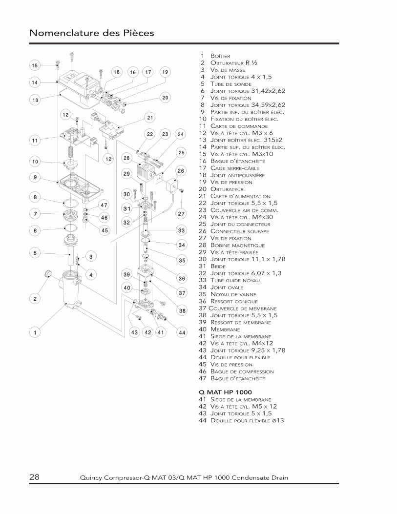
Nomenclature des Pièces
1 BOÎTIER
2 OBTURATEUR R ½ 3 VIS DE MASSE
4 JOINT TORIQUE 4 X 1,5 5 TUBE DE SONDE
6 JOINT TORIQUE 31,42X2,62 7 VIS DE FIXATION
8 JOINT TORIQUE 34,59X2,62 9 PARTIE INF. DU BOÎTIER ÉLEC.10 FIXATION DU BOÎTIER ÉLEC.11 CARTE DE COMMANDE
12 VIS À TÊTE CYL. M3 X 613 JOINT BOÎTIER ÉLEC. 315X2 14 PARTIE SUP. DU BOÎTIER ÉLEC.15 VIS À TÊTE CYL. M3X1016 BAGUE D’ÉTANCHÉITÉ
17 CAGE SERRE-CÂBLE
18 JOINT ANTIPOUSSIÈRE
19 VIS DE PRESSION
20 OBTURATEUR
21 CARTE D’ALIMENTATION
22 JOINT TORIQUE 5,5 X 1,523 COUVERCLE AIR DE COMM.24 VIS À TÊTE CYL. M4X3025 JOINT DU CONNECTEUR
26 CONNECTEUR SOUPAPE
27 VIS DE FIXATION
28 BOBINE MAGNÉTIQUE
29 VIS À TÊTE FRAISÉE
30 JOINT TORIQUE 11,1 X 1,7831 BRIDE
32 JOINT TORIQUE 6,07 X 1,333 TUBE GUIDE NOYAU
34 JOINT OVALE
35 NOYAU DE VANNE
36 RESSORT CONIQUE
37 COUVERCLE DE MEMBRANE
38 JOINT TORIQUE 5,5 X 1,539 RESSORT DE MEMBRANE
40 MEMBRANE
41 SIÈGE DE LA MEMBRANE
42 VIS À TÊTE CYL. M4X1243 JOINT TORIQUE 9,25 X 1,7844 DOUILLE POUR FLEXIBLE
45 VIS DE PRESSION
46 BAGUE DE COMPRESSION
47 BAGUE D’ÉTANCHÉITÉ
Q MAT HP 100041 SIÈGE DE LA MEMBRANE
42 VIS À TÊTE CYL. M5 X 1243 JOINT TORIQUE 5 X 1,544 DOUILLE POUR FLEXIBLE Ø13
28 Quincy Compressor-Q MAT 03/Q MAT HP 1000 Condensate Drain
Componentes
1 CAIXA
2 BUJÃO R ½ 3 PARAFUSO DE LIGAÇÃO À TERRA
4 ANEL EM „O“ 4 X 1,5 5 TUBO-SENSOR
6 ANEL EM „O“ 31,42X2,62 7 PARAFUSO DE FIXAÇÃO
8 ANEL EM „O“ 34,59X2,62 9 PARTE DE BAIXO DA COBERTURA
10 ELEMENTO DE FIXAÇÃO DA COBERTURA
11 PLACA DE COMANDO
12 PARAFUSO DE CABEÇA LENTICULAR M3 X 613 EMPANQUE DE CORDÃO 2X31514 PARTE DE CIMA DA COBERTURA
15 PARAFUSO DE CABEÇA LENTICULAR M3 X 1016 ANEL DE VEDAÇÃO
17 CAPA DE APERTO PARA PG918 DISCO PROTECTOR CONTRA PÓ
19 PARAFUSO DE PRESSÃO
20 BUJÃO
21 PLACA DE ALIMENTAÇÃO A PARTIR DA REDE
22 ANEL EM „O“ 5,5 X 1,523 TAMPA DO AR DE CONTROLO
24 PARAFUSO DE CABEÇA LENTICULAR M4 X 3025 EMPANQUE DE FICHA
26 LIGADOR DE VÁLVULA
27 PARAFUSO DE FIXAÇÃO
28 BOBINA INDUCTORA
29 PARAFUSO DE CABEÇA ESCAREADA M4 X 2530 ANEL EM „O“ 11,1 X 1,7831 FLANGE
32 ANEL EM „O“ 6,07 X 1,333 TUBO DE GUIA DO NÚCLEO
34 ANEL OVAL 21,8X1,5X2,535 NÚCLEO DE VÁLVULA
36 MOLA CÓNICA EM FIO METÁLICO
37 TAMPA DO DIAFRAGMA
38 5,5 X 1,539 MOLA DE PRESSÃO PARA DIAFRAGMA
40 DIAFRAGMA
41 ASSENTO DO DIAFRAGMA
42 PARAFUSO DE CABEÇA LENTICULAR M4 X 1243 ANEL EM „O“ 9,25 X 1,7844 CONECTOR DE TUBO DE BORRACHA Ø1045 PARAFUSO DE PRESSÃO 46 ANEL DE APERTO PARA PG747 ANEL DE VEDAÇÃO
Q MAT HP 1000 VARIAÇÕES
41 ASSENTO DO DIAFRAGMA
42 PARAFUSO DE CABEÇA LENTICULAR M5 X 1243 ANEL EM „O“ 5 X 1,544 TUBO DE BORRACHE Ø13
Quincy Compressor-Q MAT 03/Q MAT HP 1000 Condensate Drain 29
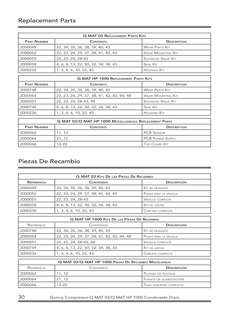
Replacement Parts
Q MAT 03 REPLACEMENT PARTS KITS
PART NUMBER CONTENTS DESCRIPTION
2000049 22, 34, 35, 36, 38, 39, 40, 43 WEAR PARTS KIT
2000052 22, 23, 24, 29, 37, 38, 41, 42, 43 VALVE MOUNTING KIT
2000055 22, 23, 24, 28-43 SOLENOID VALVE KIT
2000058 4, 6, 8, 13, 22, 30, 32, 34, 38, 43 SEAL KIT
2000232 1, 3, 4, 6, 10, 22, 43 HOUSING KIT
Q MAT HP 1000 REPLACEMENT PARTS KITS
PART NUMBER CONTENTS DESCRIPTION
2000748 22, 34, 35, 36, 38, 39, 40, 43 WEAR PARTS KIT
2000054 22, 23, 24, 29, 37, 38, 41, 42, 43, 44, 48 VALVE MOUNTING KIT
2000057 22, 23, 24, 28-43, 48 SOLENOID VALVE KIT
2000749 4, 6, 8, 13, 22, 30, 32, 34, 38, 43 SEAL KIT
2000236 1, 3, 4, 6, 10, 22, 43 HOUSING KIT
Q MAT 03/Q MAT HP 1000 MISCELLANEOUS REPLACEMENT PARTS
PART NUMBER CONTENTS DESCRIPTION
2000062 11, 12 PCB SENSOR
2000064 21, 12 PCB POWER SUPPLY
2000066 13-20 TOP COVER KIT
Piezas De Recambio
Q MAT 03 KITS DE LAS PIEZAS DE RECAMBIO
REFERENCIA CONTENIDO DESCRIPCIÓN
2000049 22, 34, 35, 36, 38, 39, 40, 43 KIT DE DESGASTE
2000052 22, 23, 24, 29, 37, 38, 41, 42, 43 PIEZAS PARA LA VÁLVULA
2000055 22, 23, 24, 28-43 VÁLVULA COMPLETA
2000058 4, 6, 8, 13, 22, 30, 32, 34, 38, 43 KIT DE JUNTAS
2000232 1, 3, 4, 6, 10, 22, 43 CARCASA COMPLETA
Q MAT HP 1000 KITS DE LAS PIEZAS DE RECAMBIO
REFERENCIA CONTENIDO DESCRIPCIÓN
2000748 22, 34, 35, 36, 38, 39, 40, 43 KIT DE DESGASTE
2000054 22, 23, 24, 29, 37, 38, 41, 42, 43, 44, 48 PIEZAS PARA LA VÁLVULA
2000057 22, 23, 24, 28-43, 48 VÁLVULA COMPLETA
2000749 4, 6, 8, 13, 22, 30, 32, 34, 38, 43 KIT DE JUNTAS
2000236 1, 3, 4, 6, 10, 22, 43 CARCASA COMPLETA
Q MAT 03/Q MAT HP 1000 PIEZAS DE RECAMBIO MISCELÁNEAS
REFERENCIA CONTENIDO DESCRIPCIÓN
2000062 11, 12 PLATINA DE PILOTAJE
2000064 21, 12 FUENTE DE ALIMENTACIÓN
2000066 13-20 TAPA SUPERIOR COMPLETA
30 Quincy Compressor-Q MAT 03/Q MAT HP 1000 Condensate Drain
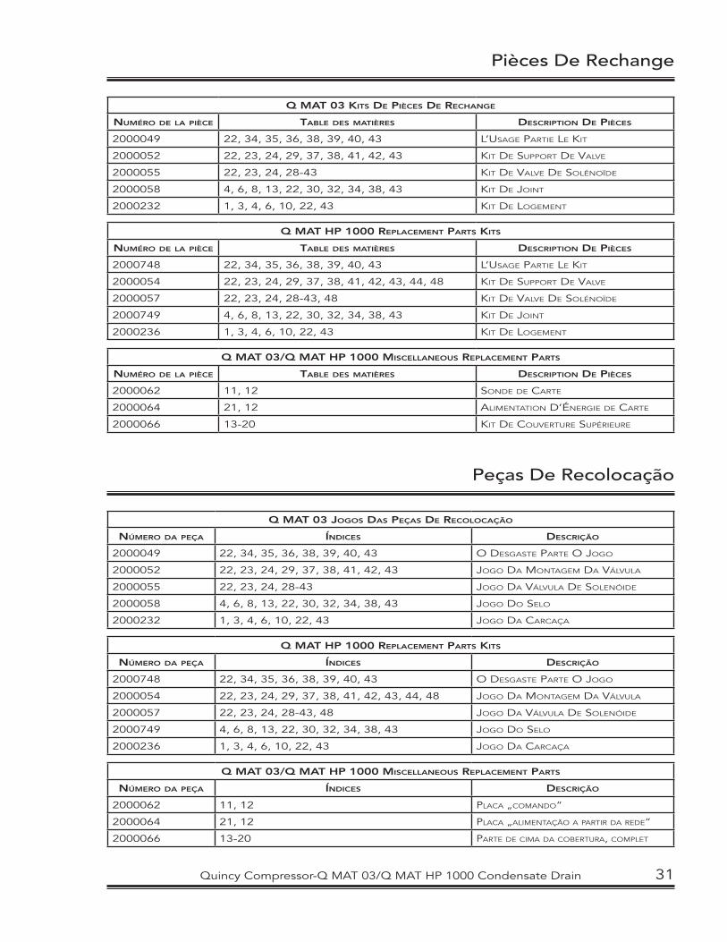
Pièces De Rechange
Q MAT 03 KITS DE PIÈCES DE RECHANGE
NUMÉRO DE LA PIÈCE TABLE DES MATIÈRES DESCRIPTION DE PIÈCES
2000049 22, 34, 35, 36, 38, 39, 40, 43 L’USAGE PARTIE LE KIT
2000052 22, 23, 24, 29, 37, 38, 41, 42, 43 KIT DE SUPPORT DE VALVE
2000055 22, 23, 24, 28-43 KIT DE VALVE DE SOLÉNOÏDE
2000058 4, 6, 8, 13, 22, 30, 32, 34, 38, 43 KIT DE JOINT
2000232 1, 3, 4, 6, 10, 22, 43 KIT DE LOGEMENT
Q MAT HP 1000 REPLACEMENT PARTS KITS
NUMÉRO DE LA PIÈCE TABLE DES MATIÈRES DESCRIPTION DE PIÈCES
2000748 22, 34, 35, 36, 38, 39, 40, 43 L’USAGE PARTIE LE KIT
2000054 22, 23, 24, 29, 37, 38, 41, 42, 43, 44, 48 KIT DE SUPPORT DE VALVE
2000057 22, 23, 24, 28-43, 48 KIT DE VALVE DE SOLÉNOÏDE
2000749 4, 6, 8, 13, 22, 30, 32, 34, 38, 43 KIT DE JOINT
2000236 1, 3, 4, 6, 10, 22, 43 KIT DE LOGEMENT
Q MAT 03/Q MAT HP 1000 MISCELLANEOUS REPLACEMENT PARTS
NUMÉRO DE LA PIÈCE TABLE DES MATIÈRES DESCRIPTION DE PIÈCES
2000062 11, 12 SONDE DE CARTE
2000064 21, 12 ALIMENTATION D’ÉNERGIE DE CARTE
2000066 13-20 KIT DE COUVERTURE SUPÉRIEURE
Peças De Recolocação
Q MAT 03 JOGOS DAS PEÇAS DE RECOLOCAÇÃO
NÚMERO DA PEÇA ÍNDICES DESCRIÇÃO
2000049 22, 34, 35, 36, 38, 39, 40, 43 O DESGASTE PARTE O JOGO
2000052 22, 23, 24, 29, 37, 38, 41, 42, 43 JOGO DA MONTAGEM DA VÁLVULA
2000055 22, 23, 24, 28-43 JOGO DA VÁLVULA DE SOLENÓIDE
2000058 4, 6, 8, 13, 22, 30, 32, 34, 38, 43 JOGO DO SELO
2000232 1, 3, 4, 6, 10, 22, 43 JOGO DA CARCAÇA
Q MAT HP 1000 REPLACEMENT PARTS KITS
NÚMERO DA PEÇA ÍNDICES DESCRIÇÃO
2000748 22, 34, 35, 36, 38, 39, 40, 43 O DESGASTE PARTE O JOGO
2000054 22, 23, 24, 29, 37, 38, 41, 42, 43, 44, 48 JOGO DA MONTAGEM DA VÁLVULA
2000057 22, 23, 24, 28-43, 48 JOGO DA VÁLVULA DE SOLENÓIDE
2000749 4, 6, 8, 13, 22, 30, 32, 34, 38, 43 JOGO DO SELO
2000236 1, 3, 4, 6, 10, 22, 43 JOGO DA CARCAÇA
Q MAT 03/Q MAT HP 1000 MISCELLANEOUS REPLACEMENT PARTS
NÚMERO DA PEÇA ÍNDICES DESCRIÇÃO
2000062 11, 12 PLACA „COMANDO“
2000064 21, 12 PLACA „ALIMENTAÇÃO A PARTIR DA REDE“
2000066 13-20 PARTE DE CIMA DA COBERTURA, COMPLET
Quincy Compressor-Q MAT 03/Q MAT HP 1000 Condensate Drain 31
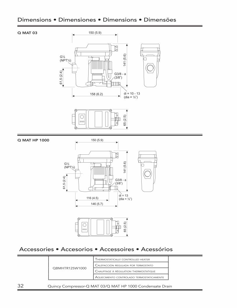
Dimensions • Dimensiones • Dimensions • Dimensões
Q MAT 03
Accessories • Accesorios • Accessoires • Acessórios
QBMHTR125W1000
THERMOSTATICALLY CONTROLLED HEATER
CALEFACCIÓN REGULADA POR TERMOSTATO
CHAUFFAGE À RÉGULATION THERMOSTATIQUE
AQUECIMENTO CONTROLADO TERMOSTATICAMENTE
Q MAT HP 1000
32 Quincy Compressor-Q MAT 03/Q MAT HP 1000 Condensate Drain
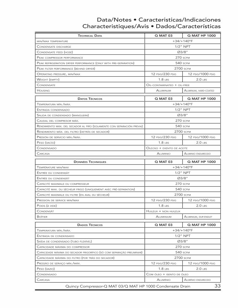
Data/Notes • Caracteristicas/IndicacionesCharacteristiques/Avis • Dados/Características
TECHNICAL DATA Q MAT 03 Q MAT HP 1000
MIN/MAX TEMPERATURE +34/+140°F
CONDENSATE DISCHARGE 1/2” NPT
CONDENSATE FEED (HOSE) Ø3/8”
PEAK COMPRESSOR PERFORMANCE 270 SCFM
PEAK REFRIGERATION DRYER PERFORMANCE (ONLY WITH PRE-SEPARATION) 540 SCFM
PEAK FILTER PERFORMANCE (BEHIND DRYER) 2700 SCFM
OPERATING PRESSURE, MIN/MAX 12 PSIG/230 PSIG 12 PSIG/1000 PSIG
WEIGHT (EMPTY) 1.8 LBS 2.0 LBS
CONDENSATE OIL-CONTAMINATED + OIL-FREE
HOUSING ALUMINUM ALUMINUM, HARD-COATED
DATOS TÉCNICOS Q MAT 03 Q MAT HP 1000
TEMPERATURA MÍN./MÁX. +34/+140°F
ENTRADA CONDENSADO 1/2” NPT
SALIDA DE CONDENSADO (MANGUERA) Ø3/8”
CAUDAL DEL COMPRESOR MÁX. 270 SCFM
RENDIMIENTO MÁX. DEL SECADOR AL FRÍO (SOLAMENTE CON SEPARACIÓN PREVIA) 540 SCFM
RENDIMIENTO MÁX. DEL FILTRO (DETRÁS DE SECADOR) 2700 SCFM
PRESIÓN DE SERVICIO MÍN./MÁX. 12 PSIG/230 PSIG 12 PSIG/1000 PSIG
PESO (VACÍO) 1.8 LBS 2.0 LBS
CONDENSADO OLEOSO + EXENTO DE ACEITE
CARCASA ALUMINIO ALUMINIO ENDURECIDO
DONNÉES TECHNIQUES Q MAT 03 Q MAT HP 1000
TEMPÉRATURE MIN/MAX +34/+140°F
ENTRÉE DU CONDENSÂT 1/2” NPT
ENTRÉE DU CONDENSÂT Ø3/8”
CAPACITÉ MAXIMALE DU COMPRESSEUR 270 SCFM
CAPACITÉ MAX. DU SÉCHEUR FRIGO (UNIQUEMENT AVEC PRÉ-SEPARATION) 540 SCFM
CAPACITÉ MAXIMALE DU FILTRE (EN AVAL DU SÉCHEUR) 2700 SCFM
PRESSION DE SERVICE MIN/MAX 12 PSIG/230 PSIG 12 PSIG/1000 PSIG
POIDS (À VIDE) 1.8 LBS 2.0 LBS
CONDENSÂT HUILEUX + NON HUILEUX
BOÎTIER ALUMINIUM ALUMINIUM, DUR-ENDUIT
DADOS TÉCNICOS Q MAT 03 Q MAT HP 1000
TEMPERATURA MÍN./MÁX. +34/+140°F
ENTRADA DE CONDENSADO 1/2” NPT
SAÍDA DE CONDENSADO (TUBO FLEXÍVEL) Ø3/8”
CAPACIDADE MÁXIMA DO COMPRESSOR 270 SCFM
CAPACIDADE MÁXIMA DO SECADOR FRIGORÍFICO (SÓ COM SEPARAÇÃO PRELIMINAR) 540 SCFM
CAPACIDADE MÁXIMA DO FILTRO (POR TRÁS DO SECADOR) 2700 SCFM
PRESSÃO DE SERVIÇO MÍN./MÁX. 12 PSIG/230 PSIG 12 PSIG/1000 PSIG
PESO (VAZIO) 1.8 LBS 2.0 LBS
CONDENSADO COM ÓLEO + ISENTO DE ÓLEO
CARCASA ALUMÍNIO ALUMÍNIO ENDURECIDO
Quincy Compressor-Q MAT 03/Q MAT HP 1000 Condensate Drain 33
STANDARD TERMS AND CONDITIONS
QUINCY COMPRESSOR AND ORTMAN FLUID POWER DIVISIONS
LEGAL EFFECT: Except as expressly otherwise agreed to in writing by an authorized representative of Seller, the following terms and conditions shall apply to and form a part of this order and any additional and/or different terms of Buyer’s purchase order or other form of acceptance are rejected in advance and shall not become a part of this order.
The rights of Buyer hereunder shall be neither assignable nor transferable except with the written consent of Seller.
This order may not be canceled or altered except with the written consent of Seller and upon terms which will indemnify Seller against all loss occasioned thereby. All additional costs incurred by Seller due to changes in design or specifications, modification of this order or revision of product must be paid for by Buyer.
In addition to the rights and remedies conferred upon Seller by this order, Seller shall have all rights and remedies conferred at law and in equity and shall not be required to proceed with the performance of this order if Buyer is in default in the performance of such order or of any other contract or order with seller.
TERMS OF PAYMENT: Unless otherwise specified in the order acknowledgment, the terms of payment shall be net cash within thirty (30) days after shipment. These terms shall apply to partial as well as complete shipments. If any proceeding be initiated by or against Buyer under any bankruptcy or insolvency law, or in the judgment of Seller the financial condition of Buyer, at the time the equipment is ready for shipment, does not justify the terms of payment specified, Seller reserves the right to require full payment in cash prior to making shipment. If such payment is not received within fifteen (15) days after notification of readiness for shipment, Seller may cancel the order as to any unshipped item and require payment of its reasonable cancellation charges.
If Buyer delays shipment, payments based on date of shipment shall become due as of the date when ready for shipment. If Buyer delays completion of manufacture, Seller may elect to require payment according to percentage of completion. Equipment held for Buyer shall be at Buyer’s risk and storage charges may be applied at the discretion of Seller.
Accounts past due shall bare interest at the highest rate lawful to contract for but if there is no limit set by law, such interest shall be eighteen percent (18%). Buyer shall pay all cost and expenses, including reasonable attorney’s fees, incurred in collecting the same, and no claim, except claims within Seller’s warranty of material or workmanship, as stated below, will be recognized unless delivered in writing to Seller within thirty (30) days after date of shipment.
TAXES: All prices exclude present and future sales, use, occupation, license, excise, and other taxes in respect of manufacture, sales or delivery, all of which shall be paid by Buyer unless included in the purchase price at the proper rate or a proper exemption certificate is furnished.
ACCEPTANCE: All offers to purchase, quotations and contracts of sales are subject to final acceptance by an authorized representative at Seller’s plant.
DELIVERY: Except as otherwise specified in this quotation, delivery will be F. O. B. point of shipment. In the absence of exact shipping instruction, Seller will use its discretion regarding best means of insured shipment. No liability will be accepted by Seller for so doing. All transportation charges are at Buyer’s expense. Time of delivery is an estimate only and is based upon the receipt of all information and necessary approvals. The shipping schedule shall not be construed to limit seller in making commitments for materials or in fabricating articles under this order in accordance with Seller’s normal and reasonable production schedules.
Seller shall in no event be liable for delays caused by fires, acts of God, strikes, labor difficulties, acts of governmental or military authorities, delays in transportation or procuring materials, or causes of any kind beyond Seller’s control. No provision for liquidated damages for any cause shall apply under this order. Buyer shall accept delivery within thirty (30) days after receipt of notification of readiness for shipment. Claims for shortages will be deemed to have been waived if not made in writing within ten (10) days after the receipt of the material in respect of which any such shortage is claimed. Seller is not responsible for loss or damage in transit after having received “In Good Order” receipt from the carrier. All claims for loss or damage in transit should be made to the carrier.
34 Quincy Compressor-Q MAT 03/Q MAT HP 1000 Condensate Drain
STANDARD TERMS AND CONDITIONS
QUINCY COMPRESSOR AND ORTMAN FLUID POWER DIVISIONS
TITLE & LIEN RIGHTS: The equipment shall remain personal property, regardless of how affixed to any realty or structure. Until the price (including any notes given therefore) of the equipment has been fully paid in cash, Seller shall, in the event of Buyer’s default, have the right to repossess such equipment.
PATENT INFRINGEMENT: If properly notified and given an opportunity to do so with friendly assistance, Seller will defend Buyer and the ultimate user of the equipment from any actual or alleged infringement of any published United States patent by the equipment or any part thereof furnished pursuant hereto (other than parts of special design, construction, or manufacture specified by and originating with Buyer), and will pay all damages and costs awarded by competent court in any suit thus defended or of which it may have had notice and opportunity to defend as aforesaid.
STANDARD WARRANTY: Seller warrants that products of its own manufacture will be free from defects in workmanship and materials under normal use and service for the period specified in the product instruction manual. Warranty for service parts will be ninety (90) days from date of factory shipment. Electric Motors, gasoline and diesel engines, electrical apparatus and all other accessories, components and parts not manufactured by Seller are warranted only to the extent of the original manufacturer’s warranty.
Notice of the alleged defect must be given to the Seller, in writing with all identifying details including serial number, type of equipment and date of purchase within thirty (30) days of the discovery of the same during the warranty period.
Seller’s sole obligation on this warranty shall be, at its option, to repair or replace or refund the purchase price of any product or part thereof which proves to be defective. If requested by Seller, such product or part thereof must be promptly returned to seller, freight prepaid, for inspection.
Seller warrants repaired or replaced parts of its own manufacture against defects in materials and workmanship under normal use and service for ninety (90) days or for the remainder of the warranty on the product being repaired.
This warranty shall not apply and Seller shall not be responsible or liable for:
(a) Consequential, collateral or special losses or damages;
(b) Equipment conditions caused by fair wear and tear, abnormal conditions of use, accident, neglect or misuse of equipment, improper storage or damage resulting during shipping;
(c) Deviation from operating instructions, specifications or other special terms of sale;
(d) Labor charges, loss or damage resulting from improper operation, maintenance or repairs made by person(s) other than Seller or Seller’s authorized service station.
In no event shall Seller be liable for any claims whether arising from breach of contract or warranty or claims of negligence or negligent manufacture in excess of the purchase price.
THIS WARRANTY IS THE SOLE WARRANTY OF SELLERS AND ANY OTHER WARRANTIES, WHETHER EXPRESS OR IMPLIED IN LAW OR IMPLIED IN FACT, INCLUDING ANY WARRANTIES OF MERCHANTABILITY AND FITNESS FOR PARTICULAR USE ARE HEREBY SPECIFICALLY EXCLUDED.
LIABILITY LIMITATIONS: Under no circumstances shall the Seller have any liability for liquidated damages or for collateral, consequential or special damages or for loss of profits, or for actual losses or for loss of production or progress of construction, whether resulting from delays in delivery or performance, breach of warranty, negligent manufacture or otherwise.
ENVIRONMENTAL AND OSHA REQUIREMENTS: At the time of shipment of the equipment from the factory, Quincy Compressor / Ortman Fluid Power will comply with the various Federal, State and local laws and regulations concerning occupational health and safety and pollution. However, in the installation and operation of the equipment and other matters over which the seller has no control, the Seller assumes no responsibility for compliance with those laws and regulations, whether by the way of indemnity, warranty or otherwise.
Quincy Compressor-Q MAT 03/Q MAT HP 1000 Condensate Drain 35

Notes
____________________________________________________________________________________________________________________________________________________________________________________________________________________________________________________________________________________________________________________________________________________________________________________________________________________________________________________________________________________________________________________________________________________________________________________________________________________________________________________________________________________________________________________________________________________________________________________________________________________________________________________________________________________________________________________________________________________________________________________________________________________________________________________________________________________________________________________________________________________________________________________________________________________________________________________________________________________________________________________________________________________________________________________________________________________________________________________________________________________________________________________________________________________________________________________________________________________________________________________________________________________________________________________________________________________________________________________________________________________________________________________________________________________________________________________________________________________________________________________________________________________________________________________________________________________________________________________________________________________________________________________________________________________________________________________________________________________________________________________________________________________________________________________________________________________________________________________________________________
36 Quincy Compressor-Q MAT 03/Q MAT HP 1000 Condensate Drain


© 2006 Quincy Compressor
All Rights Reserved. Litho in U.S.A.
Quincy Compressor Products: 217.222.7700
E-mail: [email protected]
Website: www.quincycompressor.com