Embed Size (px)
Citation preview

Oracle® Hospitality SimphonyConfiguration Guide
Release 2.8E66799-05March 2018
Oracle Hospitality Simphony Configuration Guide, Release 2.8
E66799-05
Copyright © 2010, 2018, Oracle and/or its affiliates. All rights reserved.
This software and related documentation are provided under a license agreement containing restrictions onuse and disclosure and are protected by intellectual property laws. Except as expressly permitted in yourlicense agreement or allowed by law, you may not use, copy, reproduce, translate, broadcast, modify,license, transmit, distribute, exhibit, perform, publish, or display any part, in any form, or by any means.Reverse engineering, disassembly, or decompilation of this software, unless required by law forinteroperability, is prohibited.
The information contained herein is subject to change without notice and is not warranted to be error-free. Ifyou find any errors, please report them to us in writing.
If this is software or related documentation that is delivered to the U.S. Government or anyone licensing it onbehalf of the U.S. Government, then the following notice is applicable:
U.S. GOVERNMENT END USERS: Oracle programs, including any operating system, integrated software,any programs installed on the hardware, and/or documentation, delivered to U.S. Government end users are"commercial computer software" pursuant to the applicable Federal Acquisition Regulation and agency-specific supplemental regulations. As such, use, duplication, disclosure, modification, and adaptation of theprograms, including any operating system, integrated software, any programs installed on the hardware,and/or documentation, shall be subject to license terms and license restrictions applicable to the programs.No other rights are granted to the U.S. Government.
This software or hardware is developed for general use in a variety of information management applications.It is not developed or intended for use in any inherently dangerous applications, including applications thatmay create a risk of personal injury. If you use this software or hardware in dangerous applications, then youshall be responsible to take all appropriate fail-safe, backup, redundancy, and other measures to ensure itssafe use. Oracle Corporation and its affiliates disclaim any liability for any damages caused by use of thissoftware or hardware in dangerous applications.
Oracle and Java are registered trademarks of Oracle and/or its affiliates. Other names may be trademarks oftheir respective owners.
Intel and Intel Xeon are trademarks or registered trademarks of Intel Corporation. All SPARC trademarks areused under license and are trademarks or registered trademarks of SPARC International, Inc. AMD, Opteron,the AMD logo, and the AMD Opteron logo are trademarks or registered trademarks of Advanced MicroDevices. UNIX is a registered trademark of The Open Group.
This software or hardware and documentation may provide access to or information about content, products,and services from third parties. Oracle Corporation and its affiliates are not responsible for and expresslydisclaim all warranties of any kind with respect to third-party content, products, and services unless otherwiseset forth in an applicable agreement between you and Oracle. Oracle Corporation and its affiliates will not beresponsible for any loss, costs, or damages incurred due to your access to or use of third-party content,products, or services, except as set forth in an applicable agreement between you and Oracle.
Contents
1 Introduction to Simphony
2 Enterprise
Enterprise Organization 2-2
Inheritance and Overrides 2-2
Configuring Permissions for the Enterprise 2-3
Understanding CAL Packages 2-4
Overview of CAL Package Deployment 2-7
Configuring CAL Package Permissions 2-8
Configuring CAL Packages 2-8
Resizing the Initial Workstation Database 2-9
Changing a Custom CAL Package 2-10
CAL Deployment Order 2-11
Adding a Deployment Schedule for the Current CAL Package 2-12
Adding a Deployment Schedule for a Group of CAL Packages 2-13
Viewing CAL Package Deployment Schedules 2-14
Changing a CAL Package Version 2-14
Viewing, Reloading, and Saving CAL Package Contents 2-15
Manually Deploying CAL Packages 2-15
Updating CAL Client Workstations 2-16
Distributing CAL from a Property Application Server 2-16
Configuring the Distributed CAL (DCAL) Server 2-17
Changing the CAL Server Location 2-18
Moving the DCAL Server to Another Service Host 2-18
Configuring a DCAL Download Schedule 2-18
Reviewing the DCAL File Download Status 2-19
Pairing a New Workstation With a DCAL Server 2-19
3 Properties
Adding a Property 3-1
Adding a Revenue Center 3-2
iii

Overview of Adding a Workstation 3-3
Adding a Workstation 3-3
Configuring Workstation Transaction Settings 3-5
Setting Offline Transaction Posting Time 3-6
Configuring Workstation Security 3-6
Configuring the Magnetic Stripe Reader on the Oracle MICROS Tablet 720 3-8
Configuring the Barcode Scanner on the Oracle MICROS Tablet 720 3-8
Integration with the Android Mobile Operating System 3-8
Android Devices and Versions 3-9
Android Functionality Support 3-10
Android Network Requirements 3-10
Android Payments 3-11
Configuring the Android Device 3-11
Configuring the Android Device as a Workstation 3-12
Setting the CAL Package for the Android Device 3-12
Installing the Client Application Loader (CAL) on the Android Device 3-13
Installing the Simphony Service Host 3-14
Viewing and Editing Simphony Android Files 3-14
Setting Languages 3-15
4 Employees and Privileges
Setting Employee Roles 4-1
Creating Employee Classes 4-3
Adding an Employee 4-4
Terminating an Employee 4-5
Changing Employee Information 4-5
Configuring Employee Shifts 4-7
Configuring Employee Breaks 4-9
Clock-In and Clock-Out Cycles 4-10
Setting Clock-In and Clock-Out Cycles 4-10
Job Codes 4-11
Configuring Job Codes 4-11
Understanding Tip Tracking 4-12
Configuring Tip Tracking and Reporting 4-13
Configuring Tip Track Front of House Buttons 4-14
5 Payments and Currency
Types of Payment 5-2
Configuring Base Currency and Alternate Currency 5-2
iv

Configuring Currency Conversions 5-3
Configuring the Cash Tender 5-4
Credit Card Tokenization 5-5
Loadable Payment Card Configuration Tasks 5-5
Loadable Payment Configuration Prerequisites 5-6
Universal Transaction Gateway for Shift4 5-7
Communication Methods for Fusebox Payment Card Driver 5-8
stunnel Installation Methods 5-8
Installing stunnel at a Single Host Location 5-9
Installing stunnel Through Simphony as a CAL Package 5-9
Configuring the CAPMS Payment Card Driver 5-10
Configuring the CAPMS Payment Module 5-11
Configuring the Dollars on the Net Payment Card Driver 5-13
Configuring the Dollars on the Net Payment Module 5-14
Configuring the Fusebox Payment Card Driver 5-16
Configuring the Fusebox Payment Module 5-18
Configuring the VisaD Payment Card Driver 5-20
Configuring the VisaD Payment Module 5-22
Configuring the Loadable Payment Card Device 5-23
Creating Front of House Loadable Payment Card Buttons 5-24
Distributing a Third-Party Credit Card Driver Package 5-24
Copying Third-Party Payment Driver Files 5-25
Creating a CAL Package for the Third-Party Payment Card Driver Distribution 5-25
Credit Card Batching 5-26
Creating a Credit Card Batch 5-26
Editing a Credit Card Batch 5-26
Settling a Credit Card Batch 5-27
Credit Card Preamble 5-27
Credit Card Preamble Rules 5-27
Updating Standard Credit Card Preambles 5-28
List of Standard Credit Card Preambles for the U.S. 5-28
Pay at the Table 5-29
Configuring a Credit Card Tender 5-30
Configuring the Room Tender 5-31
Configuring the OPERA PMS Payment Driver 5-31
Configuring the MICROS Standard Credit Card Payment Module 5-32
Configuring the Loadable PMS Payment Module 5-35
Configuring the Demo Payment 5-36
Setting the Front of House to Allow Pay at the Table 5-36
Configuring Email Receipts 5-38
Autosequence Events 5-39
v

Configuring Autosequence Events 5-39
Configuring the Autosequence Event Schedule 5-40
6 Taxes
Understanding Tax Rates and Tax Classes 6-2
Serving Periods 6-3
Configuring a Serving Period 6-3
Order Types 6-4
Configuring Order Types 6-5
Configuring Order Types as Subtotal Keys 6-6
Configuring Tax Rates and Classes 6-7
Understanding Tax Labels 6-8
Configuring Tax Labels 6-8
Printing Tax Rate Per Item 6-8
Configuring Tax Rates Per Item to Print on Guest Check, Customer Receipt andJournal 6-9
Configuring Workstation Number and Transaction Number to Print on Guest Check,Customer Receipt, and Journal 6-10
7 Discounts
Automatic Discounts 7-2
Understanding Automatic Discount Rules 7-3
Understanding Awarding Algorithms 7-3
Discount Award Types 7-5
Discount Exclusivity 7-5
Simple Exclusivity 7-6
Group Exclusivity 7-7
Menu Item Groups 7-8
Configuring Discount Privileges 7-8
Configuring Discounts 7-9
Understanding Automatic Discounts with Decimal Quantity Menu Items 7-13
Amount Off Examples 7-13
Amount Substitution Examples 7-14
Configuring Decimal Quantity Menu Items 7-15
Configuring a Combination Pricing Discount 7-15
Applying Discounts Using Condiments 7-16
Configuring the Condiment as the Trigger 7-17
Configuring Parent Menu Item Class Discounts 7-17
Configuring the Discount for a Condiment 7-18
Creating the Discount Button 7-19
vi

Configuring Menu Item Groups 7-19
8 Service Charges
Configuring Service Charges 8-1
9 Setting Up Menu Items
Menu Item Programming Best Practices 9-2
Major Groups 9-3
Family Groups 9-3
Menu Item Master and Menu Item Definitions 9-3
Menu Item Classes 9-4
Menu Item Pricing 9-5
Screen Look Up (SLU) 9-6
Number Look Up (NLU) 9-6
Menu Levels 9-7
Sales Itemizers 9-9
Configuring Major Groups 9-10
Configuring Family Groups 9-10
Configuring Menu Item Classes 9-10
Configuring Menu Item Prices 9-12
Setting Main, Sub, and Custom Menu Levels 9-13
Setting the Default Main and Sub Levels for Serving Periods 9-14
Configuring Auto Menu Levels 9-14
Setting the Default Menu Levels for a Revenue Center 9-15
Configuring Active Menu Levels for Menu Item Definitions 9-15
Configuring Menu Item Functionality on the Workstation 9-16
Configuring Sales Itemizers 9-17
Configuring Master Records for Menu Items 9-17
Configuring Menu Item Definitions 9-18
Adding and Disabling Menu Items 9-19
Configuring Menu Item Availability from the EMC 9-20
Configuring Menu Item Availability for Multiple Definitions at the Workstation 9-20
Configuring a Weighed Menu Item 9-20
Understanding Tare Weight 9-21
Setting the Tare Weight for a Menu Item 9-21
Menu Item Fees 9-22
Configuring Menu Item Fees 9-22
Configuring Screen Look Ups for Menu Items 9-23
Configuring Screen Look Ups for Discounts 9-24
vii
Configuring Screen Look Ups for Service Charges 9-24
Configuring Screen Look Ups for Tender/Media Records 9-25
Configuring Screen Look Ups for Family Groups 9-25
Configuring Screen Look Ups for Major Groups 9-26
Configuring Screen Look Ups for Custom Reports 9-26
Configuring Screen Look Ups for Open Checks 9-26
Configuring Number Look Ups for Discounts 9-27
Configuring Number Look Ups for Service Charges 9-28
Configuring Number Look Ups for Tender/Media Records 9-28
Configuring Number Look Ups for Main and Sub Levels 9-29
Menu Item Waste Checks 9-29
Allowing Employees to Begin Waste Checks and Run Waste Check Reports 9-30
Configuring Waste Reasons 9-31
Configuring Waste Receipt Headers and Trailers 9-31
Hiding Price Details on Waste Checks 9-32
Creating the Declare Waste Button 9-32
Menu Item Waste Reports 9-33
10
Condiments
Condiment Groups and Condiment Sets 10-2
Configuring Condiment Groups 10-2
Creating Menu Item Classes for Condiment Groups 10-3
Creating Menu Item Master Records for Condiments 10-3
Configuring Condiment Sets 10-4
Assigning Condiments to Parent Menu Item Classes 10-4
Assigning Default Condiments to Parent Menu Items 10-6
Condiment Prefixes 10-6
Creating Condiment Prefix Menu Items 10-7
Creating Menu Items Classes for Prefixes 10-7
Activating Condiment Prefixes 10-8
Deactivating Condiment Prefixes 10-8
Configuring Touchscreen Buttons for Condiment Prefixes 10-9
Setting Condiment Appearance 10-9
Understanding the Popup Condiment Orderer 10-10
Configuring a Popup Condiment Orderer Page 10-10
Configuring a Revenue Center to Use the Popup Condiment Orderer 10-11
Configuring a Menu Item Class to Use the Popup Condiment Orderer 10-12
viii
11
Combo and Fixed Price Meals
Combo Meal Group Pricing 11-2
Placeholder Menu Items in Combo Meals 11-4
Creating Combo Meal Groups 11-5
Creating Combo Meals 11-8
Configuring Additional Combo Meal Settings 11-10
Creating Combo Meal Pages 11-11
Combo Meal Function Keys 11-12
12
Workstation Touchscreen Pages
Configuring Function Keys 12-1
Adding Menu Item Keys to the Transaction Page 12-2
Adding a Service Total Key to the Transaction Page 12-2
Adding Payment Keys to the Transaction Page 12-3
Adding Discount and Service Charge Keys to the Transaction Page 12-3
Configuring Macros 12-4
13
Guest Checks
Configuring Guest Check Numbers 13-2
Configuring Guest Check Headers and Trailers 13-2
Creating a Tender to End the Current Service Round of Checks 13-3
Understanding Fast Transactions 13-4
Configuring Fast Transactions 13-4
Understanding Full Seat Checks 13-5
Configuring the Workstation to Print Full Seat Checks 13-6
Creating a Full Seat Check Button 13-6
Splitting Off an Item 13-7
Configuring a Split Off Item Button 13-8
Conversational Ordering 13-8
Creating Menu Item Master Groups for Conversational Ordering 13-9
Configuring Menu Level Sets for Conversational Ordering 13-9
Configuring Menu Item Classes for Conversational Ordering 13-10
Configuring Menu Items for Conversational Ordering 13-11
Creating Front of House Buttons for Conversational Ordering 13-13
Configuring Employee Privileges for Automatic Check Firing 13-13
Configuring Automatic Check Firing 13-14
Understanding Suspend and Resume 13-15
Configuring Suspend and Resume 13-16
Creating a Suspend and Resume Button 13-16
ix

Setting the Employee Auto Sign Out Period 13-16
Understanding Follow Me 13-17
Configuring Follow Me Checks 13-17
Order Handling on Open Checks 13-18
Holding and Sending Items to Order Devices 13-18
Setting the Service Total to Send Items to be Prepared While the Check RemainsOpen 13-19
Setting the Hold and Fire Option 13-19
Setting the Hold and Fire Tender Notification 13-20
Setting a Reminder for Items on Hold 13-20
Setting Checks with Items on Hold to End Current Service Round 13-20
Setting Check Handling with Held Items When Closing Checks 13-21
Printing Multiple Languages on Guest Checks and Customer Receipts 13-21
Configuring Right to Left Reading Languages 13-22
Creating a Print Language List Button 13-23
Creating Print Language Buttons 13-23
14
Resetting Daily Totals
Start of Day 14-1
Start of Day Business Rules 14-2
Start of Day with Offline Workstations or Server 14-2
Configuring Start of Day 14-3
15
Maintaining the Database
Understanding the Database Update Frequency 15-1
Setting the Database Update Frequency 15-2
Understanding the Clear Totals Operation 15-2
Running the Clear Totals Operation 15-3
16
Printers and Order Devices
Understanding Print Controller 16-2
Roll Printer 16-2
Slip Printer 16-3
Internet Protocol (IP) Printer 16-3
Bluetooth Printer 16-3
Oracle MICROS Mini Printer 16-4
Configuring a Printer 16-4
Logo Printing 16-6
Uploading a Logo to Simphony 16-7
x

Assigning a Logo to Guest Checks and Customer Receipts 16-7
Order Receipt Layouts 16-8
Configuring an Order Receipt Layout 16-8
KDS Controller 16-9
Configuring a KDS Controller 16-9
Configuring a KDS Display 16-13
Configuring the KDS Bump Bar 16-16
KDS Bump Bar Functions 16-17
Configuring KDS Course Overrides 16-18
Configuring a Backup KDS Controller 16-19
Upgrading an Order Device 16-20
Upgrading the RDC Operating System 16-21
Resetting the RDC Factory Settings 16-21
Installing the KDS Client 16-22
Configuring the Deployment Schedule to Install CAL on KDS 16-22
17
Peripheral Devices
Assigning and Unassigning a Cash Drawer 17-1
Configuring a Cash Drawer 17-2
Coin Dispenser 17-5
Configuring a Coin Dispenser 17-6
Magnetic Stripe Reader 17-6
Installing the MSR Sleeve for Oracle MICROS Tablet E-Series 8-Inch and 11-InchDevices 17-7
Configuring a Magnetic Stripe Reader 17-7
Testing the MSR Sleeve for Oracle MICROS Tablet E-Series 8-Inch and 11-InchDevices 17-8
Barcode Reader Setup Methods 17-9
Configuring a Barcode Reader Using the Barcodes Module Method 17-10
Configuring a Barcode Reader Using the Number Lookup (NLU) Method 17-11
Fingerprint Scanning 17-12
Configuring the Biometrics CAL Package Deployment 17-13
Configuring Employee Privileges for the Fingerprint Reader 17-13
Setting the Front of House to Assign Employee Personal Identification Number(PIN) 17-13
Configuring the Workstation Employee Fingerprint Sign In Options 17-14
Scanning a Fingerprint 17-14
Configuring a Scale 17-15
xi
18
Reporting
Allowing Employees to Run Reports 18-1
List of PMC Reports 18-1
Configuring Employee Privileges for Oracle Hospitality Reporting and Analytics 18-3
Configuring the Log Files for Oracle Hospitality Reporting and Analytics 18-4
19
Auditing
Understanding the Audit Trail 19-1
Using the Audit Trail 19-1
Understanding Audit This Record 19-3
Using Audit This Record 19-4
20
Dining Room Tables and Seating
Standard and Enhanced Table Management 20-2
Configuring the Standard Table Management Interface 20-3
Creating Standard Dining Tables 20-4
Table Management 20-5
Reservation List 20-5
Wait List 20-6
Table Management, Reservation, and Wait List Configuration Prerequisites 20-6
Configuring Table Management Privileges 20-7
Configuring Reservation Privileges 20-9
Configuring Wait List Privileges 20-9
Configuring Servers for Table Management 20-10
Configuring Properties for Table Management 20-11
Configuring Custom Images for Table Management 20-11
Configuring KDS or Dining Course Colors and Images for Table Management 20-11
Configuring the Service Total Tender for Table Management 20-12
Enhanced Dining Tables 20-12
Setting Dining Table Classes 20-12
Setting Enhanced Dining Table Attributes 20-13
Configuring Enhanced Dining Tables 20-14
Setting Table Decorator Images 20-15
Configuring Server and Table Availability 20-17
Setting Table Management Options 20-17
Configuring Table Suggestion Factors 20-20
Table Management Alerts 20-21
Configuring Alerts 20-22
Table Management Sections 20-22
xii

Configuring Sections 20-22
Creating the Front of House Reservation List 20-23
Creating the Front of House Wait List 20-25
Front of House Table Management Tasks 20-28
Host Command Area 20-28
Configuring the Host Command Area 20-29
Dining Table Status 20-29
Configuring the Dining Table Status 20-30
Employee Lines 20-31
Configuring Employee Lines 20-31
Section Layout 20-32
Creating a Section Layout 20-33
Creating Enhanced Dining Tables 20-33
Setting Table Management Functions in Check Detail 20-34
Creating the Employee Section Assignment Report Button 20-34
Configuring Table Cancellation Reasons 20-35
Setting Reservation Timing Parameters 20-35
Setting Wait List Timing Parameters 20-36
Reservation Periods 20-37
Configuring Effectivity 20-38
Configuring Acceptance Limits 20-38
Configuring Occupancy Limits 20-39
Configuring Seating Limits 20-40
Configuring Target Turn Times 20-41
Table Management Configuration Levels 20-42
Reservation Configuration Levels 20-43
Wait List Configuration Levels 20-43
21
Enterprise Cash Management
Configuring Data Retention Limits 21-2
Specifying Ad Hoc Reports 21-3
Configuring ECM Privileges 21-3
Allowing Users to View Blind Totals 21-9
Allowing Assigned Receptacle Access 21-9
Configuring Accounting Methods for Users 21-9
Allowing Users to Override Employee Class Options 21-10
Tracking Tender Transaction Items 21-11
Tracking Service Charge Transactions 21-11
Tracking Discount Transactions 21-11
Creating, Editing, and Deleting Cash Management Reasons 21-12
xiii
Cash Management Classes 21-12
Adding Transaction Items 21-13
Adding Counting Units 21-13
Cash Pull Threshold Set 21-14
Creating, Editing, and Deleting a Cash Pull Threshold Set 21-15
Cash Count Threshold Set 21-15
Creating, Editing, and Deleting a Cash Count Threshold Set 21-16
PAR Level Set 21-16
Creating, Editing, and Deleting a PAR Level Set 21-16
Count Sheet 21-17
Creating, Editing, and Deleting a Count Sheet 21-17
Adding and Deleting a Page 21-18
Adding and Deleting a Group 21-18
Adding and Deleting a Unit 21-19
Sorting and Modifying the Order of Pages, Groups, and Units 21-20
Viewing the Totals Page 21-20
Creating, Editing, and Deleting an Account 21-20
Creating, Editing, and Deleting a Vendor 21-20
Creating and Editing a Template 21-21
Creating, Editing, and Deactivating Receptacles 21-23
Setting Cash Management Parameters 21-24
Creating Front of House Screens 21-27
Configuring a Smart Key on a Workstation 21-30
Configuring a Till Through Extensibility 21-32
ECM Reporting 21-32
ECM Enterprise Reports 21-32
Assigning Enterprise Reports 21-33
Creating ECM Property Reports 21-33
ECM Workstation Hardware 21-34
Enterprise Cash Management Configuration Levels 21-35
22
Loyalty and Gift Card Interfaces and Drivers
Loyalty and Stored Value Configuration Prerequisites 22-2
Loyalty Configuration Tasks 22-2
Configuring Loyalty and Stored Value Privileges 22-3
Setting Loyalty Options 22-7
Configuring the Loyalty Driver 22-7
Configuring the Loyalty Module 22-9
Stored Value Configuration Tasks 22-10
Setting Stored Value Options 22-10
xiv

Configuring the Stored Value Driver 22-11
Configuring the Stored Value Module 22-13
Creating Front of House Loyalty and Stored Value Buttons 22-14
Voiding Points on a Re-opened Check 22-16
XProcessor Extension Application Migration 22-17
23
Setting Up the Web Service
Understanding Transaction Services 23-1
Configuring the Transaction Services Workstation Client 23-1
Configuring the Transaction Services Employee 23-2
24
Importing and Exporting Data
Configuring the Import/Export Service Privileges 24-1
Configuring the Import/Export Service 24-2
Increasing the Import File Size 24-2
Import/Export Service Components 24-3
25
Handling Time Zone Changes on a Moving Property
Start of Business Day 25-1
Workstation Control Privileges 25-2
Changing the Time Zone 25-2
Configuring Start of Day 25-2
Configuring Workstation Control Privileges 25-4
26
Log File Management
Modifying the Default Log Archive Purge Settings for Application Services 26-2
Enabling Log Archiving for Workstations 26-2
27
Engagement Cloud Service
Understanding the Engagement Cloud Service 27-2
System Requirements and Supported Devices 27-2
Firewall and Communication 27-2
Security Precautions 27-4
Setting File Management Permissions 27-5
Registering and Logging In 27-6
Retrieving Your Engagement Organization ID 27-6
Language Translation Tasks 27-6
xv
Adding a New Language to Hub and Welcome Pages 27-7
Adding a Language to the EMCWeb File 27-7
Adding a Language File to the Engagement Configuration Application Server 27-8
Setting Multiple Languages 27-8
Understanding Engagement Manager Procedures 27-8
Adding Engagement Manager Procedure Tiles to the Hub Page 27-9
Editing the Check Header and Trailer 27-10
Editing Bulk Menu Item Prices 27-10
Adding an Employee From a Template 27-11
Adding a New Menu Item Using an Existing Menu Item as a Template 27-12
Adding Images to Menu Items 27-13
Adding or Changing an Employee’s Profile Image 27-13
Creating Pages for Engagement Users 27-13
Modifying Pages for Engagement Users 27-13
Publishing, Unpublishing, and Republishing Pages 27-14
Assigning Logos and Colors to Pages 27-14
Understanding Tagging 27-15
Adding Tags and Creating Relationships between Pages, Employees, and Tablets 27-17
Deleting Tags 27-17
Understanding Widgets 27-17
The IP Camera Widget 27-17
Adding and Moving Widgets 27-18
Creating Tiles (Adding Widgets to a Page) 27-18
Adding Command Buttons 27-21
Understanding Widget Timing Values 27-21
Configuring Widget Timing Values 27-21
List of Widgets 27-22
Viewing the Maximum Data Limit for Hosted Engagement Server 27-24
xvi

1Introduction to Simphony
Oracle Hospitality Simphony is an Enterprise-class point of sale (POS) softwareproduct. Simphony can be centrally hosted at Oracle’s datacenters, or customers canself-host Simphony at a single property. Simphony can handle a multi-property POSconfiguration consisting of thousands of workstations generating terabytes of salesdata, as well as scale down to smaller single-property configurations.
Administrators can configure Simphony using the Back of House (BOH) EnterpriseManagement Console (EMC) application. This application allows you to set up theEnterprise, properties, revenue centers, and zones from a PC that has access to thecentral server.
Simphony interfaces with the following devices and solutions:
• Peripheral Devices
• Printers and Order Devices, such as a Kitchen Display System (KDS)
• Credit Card Drivers
• Loyalty and Gift Card Interfaces and Drivers
• Enterprise Cash Management (ECM)
• Table Management System (TMS)
• Oracle Hospitality Reporting and Analytics
• Oracle Hospitality OPERA 5 Hotel Property Systems
1-1
2Enterprise
The term Enterprise refers to the entirety of a Simphony application. Simphonysupports multiple properties, and administrators can configure each propertysomewhat independently. Each property can also coexist with other properties. TheSimphony Enterprise offers a single application for configuration of multiple stores, andallows these stores to report centrally to a single Enterprise database.
A true Enterprise Simphony configuration includes more than one property, such as afranchise environment. In addition, its flexibility is ideal for multiple-propertyenvironments even if operations differ from one property to the next. In a trueEnterprise, the importance of the Enterprise Management Console (EMC)programming hierarchy is apparent to the administrator. Some module componentsare programmed at the Enterprise and then used in various properties and revenuecenters.
Although Simphony can be installed for large multi-property environments, it can alsobe installed at a single property. This type of installation, sometimes called a single-property Enterprise, is functionally the same as a true Enterprise. However, modulesthat are programmed on the Enterprise could technically be considered property levelmodules in this environment because the Enterprise consists of one property.
• Enterprise Organization
• Inheritance and Overrides
• Configuring Permissions for the Enterprise
• Understanding CAL Packages
• Overview of CAL Package Deployment
• Configuring CAL Package Permissions
• Configuring CAL Packages
• Resizing the Initial Workstation Database
• Changing a Custom CAL Package
• CAL Deployment Order
• Adding a Deployment Schedule for the Current CAL Package
• Adding a Deployment Schedule for a Group of CAL Packages
• Viewing CAL Package Deployment Schedules
• Changing a CAL Package Version
• Viewing, Reloading, and Saving CAL Package Contents
• Manually Deploying CAL Packages
• Updating CAL Client Workstations
• Distributing CAL from a Property Application Server
• Configuring the Distributed CAL (DCAL) Server
2-1

• Changing the CAL Server Location
• Moving the DCAL Server to Another Service Host
• Configuring a DCAL Download Schedule
• Reviewing the DCAL File Download Status
• Pairing a New Workstation With a DCAL Server
Enterprise OrganizationThe Enterprise Management Console (EMC) level refers to the location where an EMCmodule is programmed. In the EMC, you can program modules for the Enterprise,property, revenue center, and zone based on the information you are configuring. Forexample, employee roles are set at the Enterprise level, because typically a companykeeps privileges the same throughout the Enterprise (for example, all bartenders havethe same privileges). Tax rates are set at the property level because a property inChicago uses different tax rates than a property in Dallas. Order devices are set at therevenue center level for a particular restaurant.
In the figure shown below, the Enterprise has two properties. One property has tworevenue centers (they might be a restaurant and bar), while the other property has onerevenue center.
Figure 2-1 Enterprise Hierarchy Organization Levels
Inheritance and OverridesWhen you program a module in the Enterprise Management Console (EMC) at theEnterprise level, the property and revenue center levels inherit the module settings.That is, the property and revenue center have the same setting as the Enterprise level.For example, a discount set at the Enterprise level is used by all properties within theEnterprise. If you want the property or revenue center to have a different configurationthan the Enterprise level, you can override the inheritance by setting the module at theproperty and revenue center levels. For example, you can configure menu items at theEnterprise level, and override the menu items for a property by changing the settingsat the property level.
Chapter 2Enterprise Organization
2-2

The list of records for each EMC module shows the Zone/Location and InheritanceType columns. The Zone/Location column shows the zone or the location (Enterprise,property, or revenue center) of each record. The Inheritance Type column indicatesthe type of inheritance for each record:
• Defined Here, No Override – This status indicates the record is defined in thelocation of the module that is open. The record does not override another record. Itis possible that another record overrides this record. (EMC is not aware of recordsbelow the current location.)
• Inherited – This status indicates the record is defined in another location, and it isinherited in the current module and location.
• Defined Here, Overriding – This status indicates the record is defined in thelocation of the module that is open. The record overrides another record from ahigher location.
You cannot edit an inherited record from a child hierarchy. When overrides exist for arecord, the lowest record location applies.
Configuring Permissions for the EnterpriseYou can set user permissions for the Enterprise Management Console (EMC)modules. The privilege options define the actions the user can perform at theEnterprise level.
1. In the EMC, select the Enterprise level, click Configuration and Roles.
2. Double-click the role type record (for example, administrator, manager or server).
3. Click the EMC Modules tab.
4. Select the appropriate module permission options for the user role. You can grantuser permissions for the following module actions:
• View – Open and view a module. If you allow a user to Edit, Add, or Delete,you must also grant View access (otherwise the user cannot open themodule).
• Edit – Update fields or records within a module.
• Add – Add records to a module.
• Delete – Delete records from a module.
If you want to grant access for all module actions, select All Modules in the GlobalAccess section for each action. The All Modules option allows you to easilyconfigure the user to View, Edit, Add, or Delete every module without individuallyselecting each option. Selecting All Modules also allows the user to access newmodules that become available in future Simphony versions. Oracle Hospitalityrecommends granting All Modules permission for an administrator type of role.
5. Click the Actions tab.
6. Select the appropriate action permissions for the role.
If you want to grant access to perform all actions, select All Actions in the GlobalAccess section. Selecting All Actions also allows the user to perform new actionsthat become available in future Simphony versions. Oracle Hospitalityrecommends granting All Actions permission for an administrator type of role.
7. Click Save.
Chapter 2Configuring Permissions for the Enterprise
2-3

Understanding CAL PackagesThe Client Application Loader (CAL) is a process that allows seamless distribution,installation, and maintenance of Simphony software from a CAL server to all Simphonyclient workstations and service hosts. CAL is the only method for installing Simphonyworkstation software and service software (such as Kitchen Display System (KDS)Controller software and System Interface Module (SIM) file access software). The CALstores software packages in the transaction database, providing a central storagelocation. The CAL allows the clients to:
• Automatically discover the Simphony CAL servers
• Obtain a list of configured workstations from the CAL servers
• Establish unique workstation IDs and network configuration (either Dynamic HostConfiguration Protocol (DHCP) or static Internet Protocol (IP)) based on theinformation received from the CAL server
Packages
Packages are a sophisticated method of distributing software to the clients. Files thatneed to be copied or run on the client are bundled together, given a name, and placedin a separate directory on the server. A CAL Package is a group of files and foldersthat are copied to workstations and other CAL-enabled devices. You can configure thepackages to be distributed to:
• All devices in the Enterprise
• Devices in selected properties
• Specific devices
CAL Directory and Package Contents
The CAL Package files and folders are located on the Simphony application server inthe EGatewayService directory. This is the most important directory. Handlers in thisdirectory process messages that are sent to the Simphony application server. TheEGatewayService directory includes the encrypted database information, as well asthe web.config file that includes important Simphony settings. The following table liststhe sub-directories that reside in the EGatewayService\CAL folder and the CALpackage contents for various types of client devices.
Table 2-1 CAL Package Contents
Directory Type of Device CAL Packages
ANDROID Devices Running the AndroidMobile Operating System
ServiceHost2.0
DC Kitchen Display System (KDS)Controllers
• DCKDS• DCKDS2.0• DCKDSPrintServer2.0• McrsCAL• McrsCAL2.0
Chapter 2Understanding CAL Packages
2-4
Table 2-1 (Cont.) CAL Package Contents
Directory Type of Device CAL Packages
MC40 Motorola MC40 • FuseboxSTunnel2.0• McrsCAL• McrsCAL2.0• ServiceHost2.0
MTABLET Oracle MICROS Tablet E-Series • McrsCAL• McrsCAL2.0• ServiceHost2.0• WSKDS2.0
PPC Mobile MICROS Devices • McrsCAL• SimphonyClient
PPC70 Mobile MICROS MC70 • McrsCAL• SimphonyClient
ServiceHosts Not Applicable Sub-directory named for theService Host ID that containsautomatically generated setupinformation for each Service Host
Win32 Any 32-bit Windows machine,such as the Oracle MICROS PCWorkstation 2015 or OracleMICROS Workstation 6
• CALVersionFixer2.0• CashManagement2.0• CMLite2.0• DigitalPersona2.0• EGateway• EGatewayPrereqs• FuseboxSTunnel2.0• McrsCAL• McrsCAL2.0• MediaViewer2.0• PosToKdsHandler• PosToKdsHandler2.0• ServiceHost2.0• ServiceHostPrereq2.0• ServiceHostPrereq2015SQL
2.0• SimphonyClient• WSKDS2.0
WS5 Oracle MICROS Workstation 5 • FuseboxSTunnel2.0• McrsCAL• McrsCAL2.0• PosToKdsHandler2.0• ServiceHost2.0• ServiceHostPrereq2.0• SimphonyClient• WebServer• WSKDS• WSKDS2.0
Chapter 2Understanding CAL Packages
2-5
Table 2-1 (Cont.) CAL Package Contents
Directory Type of Device CAL Packages
WS5A Oracle MICROS Workstation 5a • FuseboxSTunnel2.0• McrsCAL• McrsCAL2.0• PosToKdsHandler2.0• ServiceHost2.0• ServiceHostPrereq2.0• SimphonyClient• WebServer• WSKDS• WSKDS2.0
Installation and Upgrade
The configuration in the CAL Packages module of the Enterprise ManagementConsole (EMC) determines when a client receives a new CAL package. The Setup.datfile is a text file that contains installation instructions. New packages include thefollowing information in the Setup.dat file:
• Name – Identifies the CAL Package
• Version – Identifies the release version number using a four-number dottednotation format (for example, 2.800.4.25)
• Commands – Indicates what, how, and where files are placed
The Simphony installer derives an internal name and version for Simphony packagesfrom the Setup.dat file. The internal name and version typically differs from thepackage name and version. For example, ServiceHost 2.7 and ServiceHost 2.8 aretwo separate packages, but they share the same internal name, ServiceHost. Theinstaller identifies the matching internal names and prevents installing and running twoversions of ServiceHost.exe on the same client.
The CAL client uses the internal name and version from the Setup.dat file to determinewhether to download the CAL package. EMC does not allow you to configure duplicateschedules for packages with the same internal name. For example, if you have adeployment schedule for ServiceHost.2.8 to deploy to the Enterprise, adding anEnterprise deployment for ServiceHost.2.8 and ServiceHost.2.7 results in the followingerror message: Cannot save duplicate deployments.
When you upgrade Simphony to a new version, the installer does not add newdeployments (with one exception) and does not change existing packages orschedules. As a result, you do not need to change deployment schedules from Installto Skip. The installer preserves CAL packages and adds new versions.
Related Topics
• Configuring CAL Package Permissions
• Configuring CAL Packages
• Resizing the Initial Workstation Database
• Changing a Custom CAL Package
• Adding a Deployment Schedule for the Current CAL Package
Chapter 2Understanding CAL Packages
2-6
• Adding a Deployment Schedule for a Group of CAL Packages
• Viewing CAL Package Deployment Schedules
• Changing a CAL Package Version
• Viewing, Reloading, and Saving CAL Package Contents
• Manually Deploying CAL Packages
• Updating CAL Client Workstations
• CAL Deployment Order
Overview of CAL Package DeploymentDeploying a Client Application Loader (CAL) package consists of completing thefollowing tasks:
• Setting CAL Package Permissions
• Configuring CAL Packages
• Changing a Custom Package
• Understanding the Deployment Order of CAL Packages
• Adding a Deployment Schedule for the Current CAL Package
• Adding a Deployment Schedule for a Group of CAL Packages
• Viewing CAL Package Deployments
• Switching a CAL Package Version
• Viewing CAL Package Contents
• Deploying CAL Packages
• Updating CAL Clients
Related Topics
• Configuring CAL Package Permissions
• Configuring CAL Packages
• Resizing the Initial Workstation Database
• Changing a Custom CAL Package
• Adding a Deployment Schedule for the Current CAL Package
• Adding a Deployment Schedule for a Group of CAL Packages
• Viewing CAL Package Deployment Schedules
• Changing a CAL Package Version
• Viewing, Reloading, and Saving CAL Package Contents
• Manually Deploying CAL Packages
• Updating CAL Client Workstations
• CAL Deployment Order
Chapter 2Overview of CAL Package Deployment
2-7
Configuring CAL Package Permissions1. In the EMC, select the Enterprise level, click Configuration and Roles.
2. Double-click the role type record (for example, administrator, manager or server).
3. Click the EMC Modules tab.
4. Scroll to the CAL Packages file and select the View, Edit, Add, and Deletepermissions for the employee role.
5. Click Save.
Related Topics
• Understanding CAL Packages
• Overview of CAL Package Deployment
• CAL Deployment Order
Configuring CAL PackagesClient Application Loader (CAL) packages belong to the following two subgroups:
• The Simphony subgroup contains the standard packages installed by Simphony.
• The Custom subgroup contains the packages added by an administrator.
1. In the EMC, select the Enterprise level, click Setup and CAL Packages.
2. Highlight a CAL package.
3. You can click the following commands in the CAL packages tree:
Table 2-2 CAL Packages Tree Commands
Command Description
Switch View Change the grouping of CAL packages from name toversion and vice versa. For example, you can viewpackages belonging only to Simphony version 2.8.
Add Custom CAL Package Upload a CAL package from a local file system to theEnterprise Management Console (EMC) and database.Uploaded packages appear in the Custom subgroup.
Refresh Refresh the entire page.
Delete Delete the highlighted CAL package.
Related Topics
• Understanding CAL Packages
• Overview of CAL Package Deployment
• CAL Deployment Order
Chapter 2Configuring CAL Package Permissions
2-8
Resizing the Initial Workstation DatabaseYou can change the initial database size of a workstation using a CAL packageGenerate XML tool from the EMC. You configure the starting database size andgrowth pattern (Pre-sized or AutoGrow) for the Simphony client databases and the toolcreates the CAL package to be added to the application. The tool only sets the initialsize of the database. You cannot use it to shrink a database that has already growntoo large.
1. Select the Enterprise level, click Setup, and then click CAL Packages.
2. Click the Generate XML tab.
3. From the Sizing Mode drop-down list, select the method for sizing the database:
• Select AutoGrow for high volume locations where the size of the database ondisc grows through a nightly job. AutoGrow mode allows the application to sizethe database during a nightly job at a specified time. This avoids the lengthydelays of sizing until the application is not in use. Do not select this option forworkstations equipped with the 8GB Universal Disk On Chip (UDOC).
• Select PreSized for workstations with limited disc space where the Simphonydefault database sizes are not proportionate to the available space. You canset a maximum size for each database and log file, and reserve a percentageof the available disc space for non-database files. In Pre-sized mode, thedatabase is potentially sized every time the workstation Service Host starts,and the database does not grow.
4. In the Non DB Percentage field, enter a percentage (between 0 and 100) of thefree space of the disc to reserve for non-database content.
5. In the Resize Time field, enter the amount of time in hours and minutes for thenightly resize job.
The value in this field determines the time on a 24-hour clock to run the databaseresize job, which attempts to resize the database outside of business hours.Although this field is required, PreSized mode ignores the value entered as thereis no nightly resize job.
6. Select the database to configure from the Alias drop-down list. You can resize thefollowing database configurations:
• LocalDB (local datastore database)
• CPServiceDb (CAPS database)
• KDSServiceDb (KDS database)
• CMLocal (cash management database)
7. In the Data File and the Log File sections, enter the appropriate values asdescribed in the following table. To set the default database configuration, selectUse Default Values.
Chapter 2Resizing the Initial Workstation Database
2-9

Table 2-3 Data File and Log File Database Configuration
Field Description
Initial Size Enter the initial size of the database file.Define the size with a number followed byM, G, or T suffixes to indicate megabytes,gigabytes, or terabytes.
Maximum Size (AutoGrow mode only) Enter the maximum size to which thedatabase can grow. If there is not enoughunreserved space to fit the maximum size,the configuration does not validate.
The NonDB Percentage value you entereddetermines how much of the free space isnot available for the databases.
Auto Grow Floor (AutoGrow mode only) Enter the size of the free space within thedatabase that triggers a nightly grow event.If you set this value to 10M and the freespace inside the data file goes below 10M,the nightly resize job attempts to resize thedatabase.
Auto Grow Increment (AutoGrow mode only) Enter the auto growth increment for thedatabase. This value is used by the nightlyresize job when the database must grow.
8. Click the Add button.
9. Click the ellipsis point (...) button, select the destination folder, and then click OK.
10. Click the Generate button.
Related Topics
• Understanding CAL Packages
• Overview of CAL Package Deployment
• CAL Deployment Order
Changing a Custom CAL PackageYou can change the name of a custom package, its deployment order, and its platformtype.
1. In the EMC, select the Enterprise level, click Setup and CAL Packages.
2. Expand the Custom subgroup and highlight the appropriate custom CAL package.
3. Change the following information:
• Name
• Deployment Order – Enter the order in which to deploy the CAL package.CAL packages with a value of 0 (zero) are loaded before packages with avalue of 1. See CAL Deployment Order for more information.
• Platform Type – Select the type of platform to receive the CAL Package.
4. In the Limit To Services section, select specific Service Host types to deploy toworkstations.
Chapter 2Changing a Custom CAL Package
2-10
• If you do not select a service, the package deploys to every Service Hostbased on the deployment schedule.
• If you select one or more services, the package deploys only to Service Hoststhat run selected services. That is, when you configure a new service for theexisting Service Host, there is no additional deployment for the Service Host. Ifa CAL package exists that is specific to the service, the Service Hostdownloads it immediately.
For example, if you select Cash Management, you must also select the CheckAnd Posting service (CAPS) because the Enterprise Cash Managementmodule only runs on CAPS Service Hosts. This causes all Service Hosts thatrun CAPS to automatically download the Cash Management CAL package if adeployment schedule exists for the Enterprise or property.
Related Topics
• Understanding CAL Packages
• Overview of CAL Package Deployment
• CAL Deployment Order
CAL Deployment OrderBy default, all Client Application Loader (CAL) packages have a deployment order of 0(zero). This can result in packages going to workstation clients in an undesirable order.Assigning an order allows Simphony to create and place certain files or folders for onepackage, which are used later by another package in order to succeed.
Oracle Hospitality recommends deploying CAL packages in the order listed in thefollowing table:
Table 2-4 CAL Deployment Order
Deployment Order CAL Package Name
0 CAL Client
1 Platform Updates
2 SimphonyClient
3 EGatewayPrereqs and WebServer
4 EGateway
5 PosToKdsHandler
6 Interface files (for example, OPERA)
7+ Custom files (for example, WSKDS and SIM scripts)
Related Topics
• Understanding CAL Packages
• Overview of CAL Package Deployment
• Configuring CAL Package Permissions
• Configuring CAL Packages
• Resizing the Initial Workstation Database
Chapter 2CAL Deployment Order
2-11

• Changing a Custom CAL Package
• Adding a Deployment Schedule for the Current CAL Package
• Adding a Deployment Schedule for a Group of CAL Packages
• Viewing CAL Package Deployment Schedules
• Changing a CAL Package Version
• Viewing, Reloading, and Saving CAL Package Contents
• Manually Deploying CAL Packages
• Updating CAL Client Workstations
Adding a Deployment Schedule for the Current CALPackage
You can schedule Client Application Loader (CAL) packages to automatically deploy atpreset times.
1. In the CAL Packages module, expand the Simphony or Custom subgroups, andhighlight the CAL package you want to deploy.
2. Click the Deployment Schedules tab.
3. Click Add Deployment to create a new row in the deployments grid.
4. In the CAL Package field, select the version number.
5. In the Deployment Type drop-down list, select the type of deployment:
• 1 - Property/Enterprise – Click the ellipsis button and select one or moreproperties where the package will download.
• 2 - Specific Service Host – Click the ellipsis button and select one or moreservice hosts or workstations where the package will download.
6. In the Action To Take field, select one of the following options:
• If you want the deployment to proceed, select Install.
• If you want to prevent a package from being downloaded select Skip.
You can configure multiple deployment schedules for the same CAL package.Simphony uses the most granular deployment when given multiple deploymentschedules. For example, if you configure a deployment schedule for a workstationand for the property, Simphony uses the workstation deployment. If you configurea CAL package deployment for a property with Install and a deployment for aworkstation with Skip, the CAL package is not installed on the workstation.
7. (Optional) In the Effective From field, select the start date when the packagebecomes active. You can use this field to schedule Simphony upgrades.
8. (Optional) In the Effective To field, select the end date when the packagebecomes inactive.
Related Topics
• Understanding CAL Packages
• Overview of CAL Package Deployment
• CAL Deployment Order
Chapter 2Adding a Deployment Schedule for the Current CAL Package
2-12
Adding a Deployment Schedule for a Group of CALPackages
Certain nodes in the tree do not have corresponding CAL packages. You can usethese nodes to group CAL packages. For example, you can configure packages thataffect All Simphony or the Service Host.
1. In the CAL Packages module, expand the Simphony or Custom subgroups, andhighlight a node without a corresponding CAL package.
2. Click the Deployment Schedules tab.
3. Click Add Deployment.
4. From the Choose CAL Package For Deployment drop-down list, select thepackage you want to deploy.
The list of available CAL packages in the dialog changes depending on the nodehighlighted in the tree. For example, if you highlight the Simphony node, the list ofpackages contains all Simphony CAL packages. If you select the Service Hostnode, the list contains only the Service Host packages.
5. From the Deployment Type drop-down list, select the type of deployment:
• 1 - Property/Enterprise
• 2 - Specific Service Host
6. Click the ellipsis button.
7. In the Select Properties or Select Service Host dialog (depending on yourselection in Step 5), select one or more properties or Service Hosts where thepackage will download, and click OK.
• Filter lengthy lists by property number or name, or by workstation number orname.
• Select the Show already configured properties option to prevent yourselffrom configuring duplicate deployment schedule records.
• Press and hold the Ctrl key while performing a left mouse click to selectmultiple properties. You can click theSelect All or Clear All links to affect allproperties in the list.
• You can select multiple service hosts or specific workstations.
8. In the Action To Take field, select one of the following options:
• If you want the deployment to proceed, select Install.
• If you want to prevent a package from being downloaded select Skip.
You can configure multiple deployment schedules for the same CAL package.Simphony uses the most granular deployment when given multiple deploymentschedules. For example, if you configure a deployment schedule for a workstationand for the property, Simphony uses the workstation deployment. If you configurea CAL package deployment for a property with Install and a deployment for aworkstation with Skip, the CAL package is not installed on the workstation.
9. (Optional) In the Effective From field, select the start date when the packagebecomes active. You can use this field to schedule Simphony upgrades.
Chapter 2Adding a Deployment Schedule for a Group of CAL Packages
2-13

10. (Optional) In the Effective To field, select the end date when the packagebecomes inactive.
Related Topics
• Understanding CAL Packages
• Overview of CAL Package Deployment
• CAL Deployment Order
Viewing CAL Package Deployment SchedulesA deployment schedule indicates the time at which a specific client or clients willdownload a Client Application Loader (CAL) package for deployment. You mustconfigure deployment schedules in order to deploy CAL packages.
1. In the EMC, select the Enterprise level, click Setup and CAL Packages.
2. Expand the Simphony or Custom subgroups, and highlight the appropriate CALpackage.
If you want to view all deployment schedules for all CAL packages, highlight theAll node.
3. Click the Deployment Schedules tab. Previously scheduled CAL packages appearin the list.
Related Topics
• Understanding CAL Packages
• Overview of CAL Package Deployment
• CAL Deployment Order
Changing a CAL Package VersionYou can switch a Client Application Loader (CAL) package that has one version ormultiple versions.
1. To change a CAL package with one version:
a. In the CAL Packages module, delete the existing deployment.
b. Add a new deployment for the new version.
2. To change a CAL package with multiple versions:
a. In the CAL Packages module, highlight the package deployment.
b. Click Change Package Version.
c. In the Choose CAL Package For Deployment drop-down list, select theappropriate package version for deployment, and click OK.
Related Topics
• Understanding CAL Packages
• Overview of CAL Package Deployment
• CAL Deployment Order
Chapter 2Viewing CAL Package Deployment Schedules
2-14

Viewing, Reloading, and Saving CAL Package Contents1. In the EMC, select the Enterprise level, click Setup and CAL Packages.
2. Highlight the Client Application Loader (CAL) package and click the PackageContents tab. The Platforms section lists all available platform types, the Setup.datversion, and CAL package name.
3. From the Files list, select a platform to see all files included in the package.
• If you want to open the file in Notepad, click View Selected File.
• If you want to reload the entire CAL package for all platforms and files from thespecified file location, click Reload Package From Disk. You must be loggedin with the same hierarchy level as the CAL package to see this command.
After you modify an existing default or custom package, reload the package.Ensure that the Setup.dat version matches the file before it loads to avoidreloading the package on all clients.
After installation, replace the local machine with the load balanced address inSimphonyInstall.xml, and then reload the entire package.
• If you want to save the entire CAL package for all platforms and files to thespecified file location, click Save Package To Disk, select an empty outputfolder, and click OK.
Related Topics
• Understanding CAL Packages
• Overview of CAL Package Deployment
• CAL Deployment Order
Manually Deploying CAL PackagesYou can manually deploy Client Application Loader (CAL) packages immediately if youdo not want to schedule the deployment to run automatically.
1. In the EMC, select the Enterprise level, click Setup and CAL Packages.
2. Click the Deployment Schedules tab.
3. Click Add Deployment, select the following values, and click OK:
• CAL Package For Deployment
• Deployment Type
4. Select the Property or Service Host (depending on the Deployment Type)
5. In the Action to Take field, select 0 - Install.
6. (Optional) In the Effective From and Effective To fields, select the dates whenthe package becomes active and inactive.
7. Click Save. The CAL package downloads to the appropriate client workstationswithin a few minutes.
Related Topics
• Understanding CAL Packages
Chapter 2Viewing, Reloading, and Saving CAL Package Contents
2-15
• Overview of CAL Package Deployment
• CAL Deployment Order
Updating CAL Client Workstations1. Power on the workstation. The workstation connects to the Enterprise server and
checks for application updates.
2. The Client Application Loader (CAL) installs the packages according to thedeployment order specified in the Enterprise Management Console (EMC). Theworkstation might restart several times.
Related Topics
• Understanding CAL Packages
• Overview of CAL Package Deployment
• CAL Deployment Order
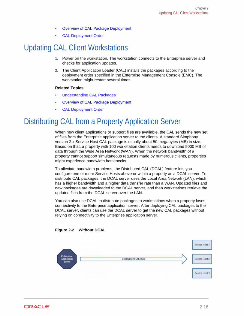
Distributing CAL from a Property Application ServerWhen new client applications or support files are available, the CAL sends the new setof files from the Enterprise application server to the clients. A standard Simphonyversion 2.x Service Host CAL package is usually about 50 megabytes (MB) in size.Based on that, a property with 100 workstation clients needs to download 5000 MB ofdata through the Wide Area Network (WAN). When the network bandwidth of aproperty cannot support simultaneous requests made by numerous clients, propertiesmight experience bandwidth bottlenecks.
To alleviate bandwidth problems, the Distributed CAL (DCAL) feature lets youconfigure one or more Service Hosts above or within a property as a DCAL server. Todistribute CAL packages, the DCAL server uses the Local Area Network (LAN), whichhas a higher bandwidth and a higher data transfer rate than a WAN. Updated files andnew packages are downloaded to the DCAL server, and then workstations retrieve theupdated files from the DCAL server over the LAN.
You can also use DCAL to distribute packages to workstations when a property losesconnectivity to the Enterprise application server. After deploying CAL packages to theDCAL server, clients can use the DCAL server to get the new CAL packages withoutrelying on connectivity to the Enterprise application server.
Figure 2-2 Without DCAL
Chapter 2Updating CAL Client Workstations
2-16
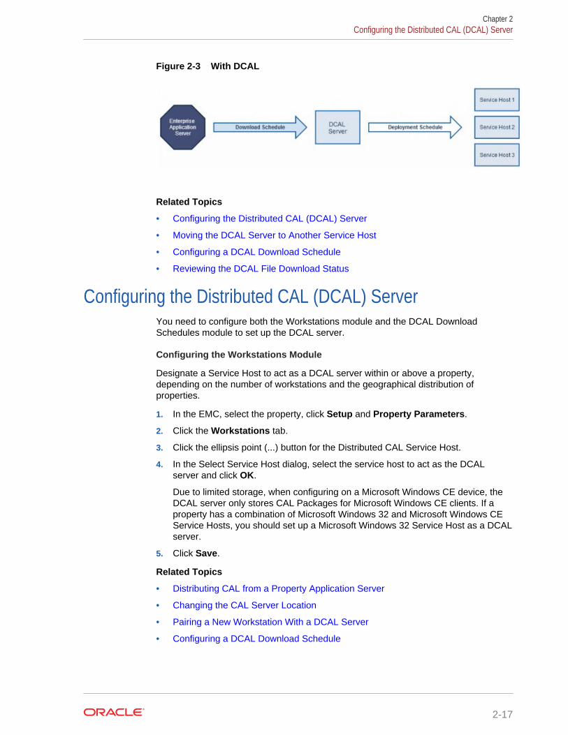
Figure 2-3 With DCAL
Related Topics
• Configuring the Distributed CAL (DCAL) Server
• Moving the DCAL Server to Another Service Host
• Configuring a DCAL Download Schedule
• Reviewing the DCAL File Download Status
Configuring the Distributed CAL (DCAL) ServerYou need to configure both the Workstations module and the DCAL DownloadSchedules module to set up the DCAL server.
Configuring the Workstations Module
Designate a Service Host to act as a DCAL server within or above a property,depending on the number of workstations and the geographical distribution ofproperties.
1. In the EMC, select the property, click Setup and Property Parameters.
2. Click the Workstations tab.
3. Click the ellipsis point (...) button for the Distributed CAL Service Host.
4. In the Select Service Host dialog, select the service host to act as the DCALserver and click OK.
Due to limited storage, when configuring on a Microsoft Windows CE device, theDCAL server only stores CAL Packages for Microsoft Windows CE clients. If aproperty has a combination of Microsoft Windows 32 and Microsoft Windows CEService Hosts, you should set up a Microsoft Windows 32 Service Host as a DCALserver.
5. Click Save.
Related Topics
• Distributing CAL from a Property Application Server
• Changing the CAL Server Location
• Pairing a New Workstation With a DCAL Server
• Configuring a DCAL Download Schedule
Chapter 2Configuring the Distributed CAL (DCAL) Server
2-17

Changing the CAL Server LocationAfter you configure a property to retrieve CAL packages from the DCAL server,workstations in the property that were pointed to the Enterprise application serverautomatically change the CAL URL to point to the DCAL server. You must restart theService Host for the changes in the CAL server to take effect.
Related Topics
• Configuring the Distributed CAL (DCAL) Server
• Moving the DCAL Server to Another Service Host
• Configuring a DCAL Download Schedule
• Reviewing the DCAL File Download Status
Moving the DCAL Server to Another Service HostIf a DCAL server was moved from one Service Host to another, all Service Hostswithin the property update the CAL URL to point to the newly defined DCAL server.You must restart the Service Host for the changes in the DCAL server to take effect.
You can see the changes made to the CAL server URL from the workstation.
1. Sign on to a workstation.
2. Click the PMC button, click PMC Home Page, and then click the General tab.
3. Review the CAL Url field and verify the changes.
Related Topics
• Distributing CAL from a Property Application Server
• Changing the CAL Server Location
• Pairing a New Workstation With a DCAL Server
Configuring a DCAL Download ScheduleDCAL Download Schedules prevent unexpected network utilization by controllingwhen the software packages are delivered to the DCAL server from the Enterpriseapplication server.
1. In the EMC, select the Enterprise level, click Setup and CAL Packages.
2. Click the DCAL Download Schedules tab.
3. Click the Add Download link.
4. In the Add Download Schedules for Distributed CAL Services dialog, select theCAL Package from the Select CAL Package drop-down list.
5. Select the properties to receive the scheduled CAL Packages, and then click OK.
6. Click the ellipsis (...) button in the Download From field, and set a time todownload the CAL Package. Leave the Download From field empty to downloadCAL Packages immediately.
Chapter 2Changing the CAL Server Location
2-18

You need to configure Deployment Schedules to deploy CAL Packages to the ServiceHosts. Without Deployment Schedules, CAL Packages are stored on the DCAL serverand are not deployed to the Service Hosts. Adding a Deployment Schedule for theCurrent CAL Package contains more information about scheduling CAL Packages todeploy at preset times.
Related Topics
• Distributing CAL from a Property Application Server
• Changing the CAL Server Location
• Pairing a New Workstation With a DCAL Server
Reviewing the DCAL File Download StatusAfter you configure and implement CAL Package download schedules, you can reviewthe availability and file download status of CAL Packages for a selected workstation.
1. In the EMC, select the Enterprise level, click Setup and CAL Packages.
2. Click the ServiceHost Status/Control tab, and then click the Add Download link.
3. Click the Install Status tab, select the search variables, and then click the Searchbutton.
Related Topics
• Distributing CAL from a Property Application Server
• Changing the CAL Server Location
• Pairing a New Workstation With a DCAL Server
Pairing a New Workstation With a DCAL ServerWhen setting up new workstations, select the application server from the workstation’sCAL client list. If you configured a DCAL server, select the DCAL server from the list.Because the DCAL server is configured to serve a property, the CAL client does notprovide a list of properties after you have selected the DCAL server as the CAL server.
Related Topics
• Configuring the Distributed CAL (DCAL) Server
• Moving the DCAL Server to Another Service Host
• Configuring a DCAL Download Schedule
• Reviewing the DCAL File Download Status
Chapter 2Reviewing the DCAL File Download Status
2-19
3Properties
A property is a place of business. A property can have one or more revenue centerswithin a confined geographic location. For example, a hotel property can have threerevenue centers (restaurant, bar, and gift shop), and a shopping mall can have severalrestaurant revenue centers. Both properties can belong to the same SimphonyEnterprise, but each property has separate sales figures, tax information, and otherconfiguration specific to the location.
• Adding a Property
• Adding a Revenue Center
• Overview of Adding a Workstation
• Adding a Workstation
• Configuring Workstation Transaction Settings
• Setting Offline Transaction Posting Time
• Configuring Workstation Security
• Configuring the Magnetic Stripe Reader on the Oracle MICROS Tablet 720
• Configuring the Barcode Scanner on the Oracle MICROS Tablet 720
• Integration with the Android Mobile Operating System
• Android Devices and Versions
• Android Functionality Support
• Android Network Requirements
• Android Payments
• Configuring the Android Device
• Configuring the Android Device as a Workstation
• Setting the CAL Package for the Android Device
• Installing the Client Application Loader (CAL) on the Android Device
• Installing the Simphony Service Host
• Viewing and Editing Simphony Android Files
• Setting Languages
Adding a Property1. In the EMC, select the Enterprise level, click Setup and Properties.
2. Insert a record.
3. On the Add Property dialog, enter the Property Number and Property Name.
4. Select the Simphony Platform from the drop-down list.
3-1
5. Select the Time Zone of the property.
6. Select the reporting location from the Report Location drop-down list. The OracleHospitality Reporting and Analytics database determines the locations that appearin the list.
a. If you want to add a new location, click the New button and enter theappropriate information. An administrator must then add the information to theOracle Hospitality Reporting and Analytics property list in order to run reports.
b. If you want to change an existing location, click the Edit button and enter theappropriate information.
7. (Optional) If you want to copy information from a property template, in the SourceProperty section select Copy from source property. The hierarchy panel andModules To Copy fields become active.
a. In the hierarchy panel, select the property to use as the source property.
b. In the Modules to Copy section, select the modules you want to copy from thesource property. To automatically select all modules, click the Select AllModules link.
c. (Optional) Select Create Clone to copy the Internet Protocol (IP) addresses ofworkstations and kitchen display system (KDS) displays and to distribute allrevenue centers and create new revenue centers. Selecting this optionessentially selects the next two options (described in Steps 7d and 7e).
d. (Optional) Select Create RVCs to create new revenue centers for the propertybased on the existing revenue centers in the template property.
e. (Optional) Select Copy IP Addresses to copy the IP addresses ofworkstations and KDS displays from the source property to the destinationproperty. (You should use this option when properties are segmented on theirown networks and IP address conflicts do not occur.)
f. (Optional) Select Distribute inherited records to distribute all records(defined and inherited) from the source property to the destination property.Deselect this option to distribute only records defined at the source property tothe destination property.
g. (Optional) Select If destination record is inherited, create override tocreate an override record in the destination property when an inheriteddefinition exists.
h. (Optional) Select Distribute Data Extensions if they exist to distribute dataextension values if they exist.
8. Click OK to copy the records from the source template property to the newproperty.
Adding a Revenue Center1. In the EMC, select the property, click Setup and RVC Configuration.
2. Insert a record.
3. On the Add Revenue Center dialog, enter the RVC Number and RVC Name.
4. (Optional) If you want to copy information from a revenue center template, in theSource Revenue Center section select Copy from source Revenue Center. Thehierarchy panel and Modules To Copy fields become active.
Chapter 3Adding a Revenue Center
3-2
a. In the hierarchy panel, select the revenue center to use as the source revenuecenter.
b. In the Modules to Copy section, select the modules you want to copy from thesource revenue center. To automatically select all modules, click the SelectAll Modules link.
c. (Optional) Select Distribute inherited records to distribute all records(defined and inherited) from the source revenue center to the new revenuecenter. Deselect this option to distribute only records defined at the sourcerevenue center to the new revenue center.
d. (Optional) Select If desination record is inherited, create override to createan override record in the new revenue center when an inherited definitionexists.
e. (Optional) Select Distribute Data Extensions if they exist to distribute dataextension values if they exist.
5. Click OK to copy the records from the source template revenue center to the newrevenue center.
6. In the table view of the RVC Configuration module, select the following options asapplicable for the new revenue center:
• LDS Active – Select this option if the revenue center uses a LiquorDispensing System (LDS), which is a third party system used for pouring andtracking liquor and beverages, as well as mixed drinks.
• KDS Controller – Select the KDS Controller to control the kitchen displaysystem (KDS) order devices in the revenue center.
7. Click Save.
Overview of Adding a WorkstationAdding a workstation consists of completing the following tasks:
• Adding a workstation
• Configuring workstation transaction settings
• Setting offline transaction posting time
• Configuring workstation security
• Configuring order device upgrades
• (Optional) Configuring integration with Android mobile operating system
Related Topics
• Adding a Workstation
• Configuring Workstation Transaction Settings
• Setting Offline Transaction Posting Time
• Configuring Workstation Security
Adding a Workstation1. In the EMC, select the property, click Setup and Workstations.
Chapter 3Overview of Adding a Workstation
3-3

2. Insert a record for the workstation, enter the name, and click OK.
3. Double-click the new workstation record.
4. On the General tab, enter information in the following fields:
Table 3-1 General Workstation Settings
Field Description
Type Select the type of workstation from the drop-down list:• Mobile MICROS – Mobile devices• Workstation Client – Workstations, virtual machines,
and Android tablets.• POSAPI Client – Simphony Transaction Services• MICROS Tablet Client – Oracle MICROS Tablet E-
Series
Language Select the default language of the workstation. This is thelanguage that appears on the workstation’s Sign In screen.If an employee has a different language set, the employeesees another language after signing in to the workstation.
Resolution Cols Enter the number of Resolution Columns for theworkstation’s display. This number should correspond toone of the resolutions set in the workstation’s .INI file, orleave it at 0 (zero) as a default.
Resolution Rows Enter the number of Resolution Rows for the workstation’sdisplay. This number should correspond to one of theresolutions set in the workstation’s .INI file, or leave it at 0(zero) as a default.
Log Verbosity Select the logging verbosity for the workstation. Forexample, select 0 (zero) for minimal logging. Highernumbers cause the workstation’s disk or flash drive to fillmore quickly.
(Optional) Workstation Class Select a Workstation Class to allow similar workstations tobe grouped together and share certain page configurationsettings.
Database Update Frequency Enter the number of seconds the workstation waits toretrieve the latest updates from the database. The defaultvalue is 60 seconds.
The value in this field overrides the Property Parameter’sDatabase Update Frequency setting.
Check Inactivity Timeout Enter the number of seconds that the workstation waitsbefore showing a message (Do you need more time?),prompting the workstation operator to cancel thetransaction. When you enter 0 (zero), the message doesnot appear.
When you select Enable Follow Me in the RVCParameters module, the check is automatically suspendedrather than cancelled.
Check Inactivity DialogTimeout
Enter the number of seconds that the workstation showsthe Inactivity dialog before automatically cancelling thetransaction. This field is dimmed when you set the CheckInactivity Timeout value to 0 (zero).
Report Timeout Enter the number of seconds the workstation waits toretrieve reporting information before failing.
Chapter 3Adding a Workstation
3-4
Table 3-1 (Cont.) General Workstation Settings
Field Description
Address / Host Name Enter the IP address or host name of the Service Hostwhere the workstation application runs.
5. Click the Revenue Centers tab.
6. Select the revenue centers for the workstation. You must select at least onerevenue center.
7. Click Save.
Related Topics
• Overview of Adding a Workstation
Configuring Workstation Transaction Settings1. In the EMC, select the property, click Setup and Workstations.
2. Double-click the workstation record to open it.
3. Click the Transactions tab and enter information in the following fields:
Table 3-2 Workstation Transaction Settings
Field Description
Minimum Check Number Enter the minimum guest check number to use:• When the workstation is in offline mode• When the workstation is used in revenue centers
without the RVC Parameters option Use RevenueCenter Check Numbers. In these revenue centers,each workstation determines its own check numberrange.
Maximum Check Number Enter the maximum guest check number to use:• When the workstation is in offline mode• When the workstation is used in revenue centers
without the RVC Parameters option Use RevenueCenter Check Numbers. In these revenue centers,each workstation determines its own check numberrange.
(Optional) Default Order Type Select the default active order type for the workstation(for example, Dine In, Take Out, or Drive Thru).
Barcode Format Set Select the barcode format for the workstation to readbarcodes of various lengths.
Cashier Link Select the cashier record to link to the workstation.Linking cashier records provides sales information, suchas menu item sales and tenders.
This field is available only when you select 8 - On =Link Cashier Totals to WS; OFF = Link to Operator inthe Workstations Options Offline/Misc sub-tab.
Merchant Group Select the merchant group, or select 0 - Use RVCSetting to use the settings from the revenue center inwhich the transaction occurs.
Chapter 3Configuring Workstation Transaction Settings
3-5
Table 3-2 (Cont.) Workstation Transaction Settings
Field Description
Thai Tax Rd Number If applicable, enter the number to print on Thai Taxtrailers.
4. Click Save.
Related Topics
• Overview of Adding a Workstation
Setting Offline Transaction Posting TimeYou can configure the posting of transactions that occur when a property or itsworkstations are unable to communicate with the database for an extended period oftime.
1. In the EMC, select the property, click Setup and Property Parameters.
2. Click the Options tab.
3. If you want offline checks to post to the database (when communications with theCheck and Posting server are re-established) with the actual time of thetransaction, select 6 - Post Offline Transactions with Actual Transaction Time.Deselect this option if you want offline checks to post with the time that the checkis uploaded into the database.
Reports run offline might not match reports run online (after all the transactionshave been played back).
4. Click Save.
Related Topics
• Overview of Adding a Workstation
Configuring Workstation Security1. In the EMC, select the property, click Setup and Workstations.
2. Double-click the workstation record to open it.
3. Click the Options tab and the Display/Security sub-tab.
4. Enter information in the following fields:
Chapter 3Setting Offline Transaction Posting Time
3-6

Table 3-3 Workstation Security Options
Security Option Description
Mag Card Entry Required forEmployee ID
Select this option to require all employeeidentification (ID) entries at the workstation to usea magnetic employee identification card (forexample, to sign in and authorize privilegedoperations). When you select this option, theworkstation does not accept an employee IDnumber entered through the keyboard ortouchscreen. Deselect this option to allow theemployee ID to be entered by either a magneticcard or by the keyboard or touchscreen.
Disable Employee Auto Sign Out Select this option to if you do not want to use theAutomatic Operator Popup Interval set in the RVCParameters module. Deselect this option to signout workstation operators after the AutomaticOperator Popup Interval expires.
Use Alternate ID for Sign-in Select this option to allow workstation operators tosign in using a four-digit alternate ID numberrather than a ten-digit employee ID number.
Fingerprint Scan Required forEmployee ID
Select this option to require all employee IDentries at the workstation to scan a fingerprint.When you select this option, the workstation doesnot accept an employee ID number enteredthrough the keyboard or touchscreen.
Employee ID or Fingerprint ScanRequired for Employee ID
Select this option to require all employee IDentries at the workstation to scan a fingerprint orenter an employee ID through the keyboard ortouchscreen. When you select this option, theworkstation only accepts an employee ID numberentered through the keyboard or touchscreen, orfingerprint scan.
Employee ID and Fingerprint ScanRequired for Employee ID
Select this option to require all employee IDentries at the workstation to scan a fingerprint andenter an employee ID through the keyboard ortouchscreen. When you select this option, theworkstation only accepts an employee ID numberentered through the keyboard or touchscreen andfingerprint scan.
Mag Card or Fingerprint ScanRequired for Employee ID
Select this option to require all employee IDentries at the workstation to scan a fingerprint orswipe a magnetic card. When you select thisoption, the workstation only accepts either amagnetic card swipe or fingerprint scan.
Mag Card and Fingerprint ScanRequired for Employee ID
Select this option to require all employee IDentries at the workstation to scan a fingerprint andswipe a magnetic card. When you select thisoption, the workstation accepts only a magneticcard swipe and fingerprint scan.
5. Click Save.
Related Topics
• Overview of Adding a Workstation
Chapter 3Configuring Workstation Security
3-7
Configuring the Magnetic Stripe Reader on the OracleMICROS Tablet 720
The Oracle MICROS Tablet 720 comes with a built-in OPOS Mag Stripe Reader(MSR).
1. In EMC, select Property, Setup, Hardware/Interfaces, Workstations, and thenDevices.
2. In the Peripheral Device Configuration section, click Add.
3. For Select Peripheral Device Type, select OPOS Mag Stripe Reader.
4. For Configuration, enter IDTECH_SECUREMAG_USBHID.
5. Click OK, and then Save.
The Oracle MICROS Tablet 720 Setup Guide contains more information on setting upand using the Tablet 720.
Configuring the Barcode Scanner on the Oracle MICROSTablet 720
The Oracle MICROS Tablet 720 comes with a built-in OPOS Barcode Scanner.
1. In EMC, select Property, Setup, Hardware/Interfaces, Workstations, and thenDevices.
2. In the Peripheral Device Configuration section, click Add.
3. For Select Peripheral Device Type, select OPOS Barcode Reader.
4. For Configuration, enter Honeywell.
5. Click OK, and then Save.
The Oracle MICROS Tablet 720 Setup Guide contains more information on setting upand using the Tablet 720.
Integration with the Android Mobile Operating SystemYou can run Simphony version 2.7 and later on devices with the Android mobileoperating system. The Simphony Point of Service (POS) client operates in a similarway on an Android mobile device and a Microsoft Windows device.
You can configure the POS client using the Enterprise Management Console (EMC),regardless of the platform. EMC manages the POS attributes, such as employees,menu items, discounts, taxes, and service charges for all Simphony client devices.System administrators use EMC to configure the pages (touchscreens) for all clients,and to deploy different user interfaces to Android devices than to traditional fixed placeworkstations.
The user interface workflow is the same on all devices and workstations. Rules areconsistent across all devices governing the sale of items, applicable discounts, andemployee functions. Android devices have special requirements that you shouldconsider if you are familiar with the traditional Microsoft platforms. These differences
Chapter 3Configuring the Magnetic Stripe Reader on the Oracle MICROS Tablet 720
3-8
include deployment methodology, configuration requirements, and the procurementprocess. Understanding these nuances and setting reasonable customer expectationsensures successful Simphony deployment with Android devices.
Related Topics
• Configuring the Android Device
• Configuring the Android Device as a Workstation
• Setting the CAL Package for the Android Device
• Installing the Client Application Loader (CAL) on the Android Device
• Installing the Simphony Service Host
• Viewing and Editing Simphony Android Files
Android Devices and VersionsSimphony is certified and supported with the following Android devices:
• Google Nexus 7 inch Tablet (one revenue center per device)
• Samsung Galaxy Note 10 inch (one revenue center per device)
• Samsung S 10 inch
• Samsung S 8 inch
Oracle recommends using one revenue center per Android device, and a maximum of10,000 menu item definitions.
The following table shows the Android versions available and supported withSimphony.
Table 3-4 Android Versions Supported with Simphony
Version Number Version Name Supported
4.1.x Jellybean No
4.2.x Jellybean No
4.3.x Jellybean No
4.4.x KitKat Yes
Related Topics
• Configuring the Android Device
• Configuring the Android Device as a Workstation
• Setting the CAL Package for the Android Device
• Installing the Client Application Loader (CAL) on the Android Device
• Installing the Simphony Service Host
• Viewing and Editing Simphony Android Files
Chapter 3Android Devices and Versions
3-9

Android Functionality SupportNote the following functionality limitations when using Simphony on an Android device:
• Simphony does not support remote access to the Android desktop for certifiedsupport applications (for example, Bomgar, Remote Desktop Protocol (RDP), andso on).
• Android devices only operate the Simphony POS client application and cannothost shared services that other devices might access.
• Android devices do not support the Check and Posting Service (CAPS). Therefore,the property must use at least one device with a Microsoft operating system inaddition to the Android device. Oracle Hospitality recommends that this device bean Oracle MICROS Workstation 5a (POSReady) or Oracle MICROS PCWorkstation 2015.
Related Topics
• Configuring the Android Device
• Configuring the Android Device as a Workstation
• Setting the CAL Package for the Android Device
• Installing the Client Application Loader (CAL) on the Android Device
• Installing the Simphony Service Host
• Viewing and Editing Simphony Android Files
Android Network RequirementsAndroid devices are connected wirelessly to Simphony using an 802.11x network,Therefore, it is vital that the property have a high quality wireless network. Spotty Wi-Ficoverage causes application performance issues with check sharing and posting, aswell as bouncing between online and offline states with the services on property (forexample, check and posting, printing and kitchen display) and the Enterprise, whichimpacts the ability to receive database updates.
You must configure the Android device to use a wireless local area network (WLAN)with connectivity to the LAN used by the Check and Posting Service and otherSimphony clients with which they might share checks. Simphony does not support theuse of a 3G or 4G connection through a telecommunications provider back to theselocal devices.
Oracle Hospitality recommends that you configure Android devices to use a staticInternet Protocol (IP) address. Simphony does not support the use of Dynamic HostConfiguration Protocol (DHCP) assigned addresses unless you define a DHCPreservation.
Related Topics
• Configuring the Android Device
• Configuring the Android Device as a Workstation
• Setting the CAL Package for the Android Device
• Installing the Client Application Loader (CAL) on the Android Device
Chapter 3Android Functionality Support
3-10

• Installing the Simphony Service Host
• Viewing and Editing Simphony Android Files
Android PaymentsThe Android clients support processing credit cards and other forms of electronicpayments.
Simphony installs several credit card payment drivers with the application. Thefollowing drivers are supported with the Android mobile operating system:
• CAPMS
• Elavon Fusebox
• mCreditDebit
• MerchantLink TV2G
• Shift4 Dollars On The Net
• VisaD
The loadable Stored Value and Loyalty modules support Android clients, and are usedwith Oracle Hospitality Gift and Loyalty and FreedomPay. The Xprocessor ExtensionApplication, which is used for third party gift cards such as Givex, does not supportAndroid devices.
Related Topics
• Configuring the Android Device
• Configuring the Android Device as a Workstation
• Setting the CAL Package for the Android Device
• Installing the Client Application Loader (CAL) on the Android Device
• Installing the Simphony Service Host
• Viewing and Editing Simphony Android Files
Configuring the Android DevicePerform the following steps before installing Simphony software.
1. Configure the Android device to be a member of the point of sale (POS) networkusing a static Internet Protocol (IP) address.
2. Install antivirus software.
3. Turn off Trusted Sources on the device. See the manufacturer instructions fordetails.
4. If you are using a Bluetooth printer, pair it with the device. See the manufacturerinstructions for details.
Related Topics
• Integration with the Android Mobile Operating System
• Android Devices and Versions
• Android Functionality Support
Chapter 3Android Payments
3-11
• Android Network Requirements
• Android Payments
Configuring the Android Device as a Workstation1. (Optional) If you are using a Bluetooth printer with the Android device, set the
printer in the Printers module. Configuring a Printer contains more informationabout setting up the printer.
2. In the EMC, select the property, click Setup and Workstations.
3. Insert a new workstation record.
4. Double-click the record to open it in form view.
5. Enter information into the workstation configuration fields, and set the Type asWorkstation Client.
6. Enter the Internet Protocol (IP) address or host name of the Service Host wherethe workstation application runs in the Address/Host Name field.
7. Click the Options tab and the Display/Security sub tab.
8. Select 39 - Floating Tablet.
9. (Optional) If you are using a Bluetooth printer, click the Printers tab and select theprinter.
10. Click Save.
Related Topics
• Integration with the Android Mobile Operating System
• Android Devices and Versions
• Android Functionality Support
• Android Network Requirements
• Android Payments
Setting the CAL Package for the Android Device1. In the EMC, select the Enterprise level, click Setup and CAL Packages.
2. Highlight the Service Host version.
3. Click the CAL Package Configuration tab.
4. Set the Platform Type for Service Host.[version] to 0 - All Clients.
5. Click the Deployment Schedules tab.
6. Set the deployment for the Service Host package for your Enterprise, property, orindividual Service Host. Adding a Deployment Schedule for the Current CALPackage contains more information about setting the deployment.
7. Click Save.
Related Topics
• Integration with the Android Mobile Operating System
• Android Devices and Versions
Chapter 3Configuring the Android Device as a Workstation
3-12
• Android Functionality Support
• Android Network Requirements
• Android Payments
Installing the Client Application Loader (CAL) on the AndroidDevice
1. Open an Internet browser window on the Android device.
2. Browse to the application server: http://[servername or IP]:8080/EGateway/Download/CAL/Android/McrsCALClient_[CALversion].apk.McrsCALClient_[CALversion].apk downloads to the device. (The CAL version islikely 129 or later.)
3. Open the Downloads menu on the Android device.
4. Touch the McrsCALClient_[CALversion].apk file to start the installation.
5. If prompted, select the device Package Installer or local application for Androidfile installation and touch Always.
6. If you receive a prompt for clearing instructions, touch OK.
7. Touch Install. CAL installs and notifies you upon completion.
8. Touch Done.
9. Press the Home button on the Android device to prompt for CAL Launcher.
10. Touch the Micros CAL option and then touch Always.
11. If you receive a prompt with instructions about defaults, touch OK. The CALLauncher home page appears. Installation of CAL is complete.
12. Touch the CAL shortcut to launch CAL Admin.
13. Enter the correct code based on the six-digit number shown at the top, and touchNext.
CAL restricts access to CAL Admin and other areas on the Android device. Youmust enter a security code to access the CAL Admin configuration and settings onthe device.
14. CAL searches for available servers. If found, the available servers appear. Touchthe desired server to populate the server information. If no servers are available,manually configure the server information.
15. Touch Next to continue.
16. Select the correct property for the device and touch Next to continue. CAL returnsa list of defined workstations for the selected property.
17. Touch the correct workstation for the device to populate the workstationinformation. If no workstations are available, manually configure the information forthe workstation.
18. Touch Save.
Related Topics
• Integration with the Android Mobile Operating System
Chapter 3Installing the Client Application Loader (CAL) on the Android Device
3-13

• Android Devices and Versions
• Android Functionality Support
• Android Network Requirements
• Android Payments
Installing the Simphony Service HostThe download and installation of Simphony ServiceHost automatically occurs. TheClient Application Loader (CAL) shows the download file progress. The estimated filesize is 558,000 kilobytes.
1. Touch Install.
2. Touch Open. ServiceHost starts and requests that you save the property andworkstation settings.
3. Touch OK. ServiceHost loads and downloads data from the Enterprise level.
4. Enter the Installer User Name for the property and touch OK.
5. Enter the Installer Password for the property and touch OK. The installation iscomplete when the login page appears.
Related Topics
• Integration with the Android Mobile Operating System
• Android Devices and Versions
• Android Functionality Support
• Android Network Requirements
• Android Payments
Viewing and Editing Simphony Android FilesAfter you install Simphony on an Android device, use the Configuration ManagementTool to view and edit certain files.
1. Launch the Simphony application on the Android device.
2. After the application loads, perform the following task on the Android device: Onevent (left swipe + right swipe + left swipe + tap + tap).
3. Enter the correct code based on the six-digit number shown at the top, and tapSign In. The Management Tool Home screen appears.
4. The following table lists the options and actions you can perform.
Table 3-5 Simphony Android Files
Option Action
View web.config.txt Tap to view and edit the web.config.txt file
View config32.web Tap to view and edit the config32.web file
View Log Tap to view the EGateway Log
Chapter 3Installing the Simphony Service Host
3-14

Table 3-5 (Cont.) Simphony Android Files
Option Action
View LogZone Tap to view the LogZone_LoadHandlers.txtfile, which is not editable
Ping Server Tap to view the Server Name or IP Address
Delete DataStore Tap to delete the DataStore database fileand restart the application on the device
Copy DataStore Tap to copy the DataStore database filewithin the device
Related Topics
• Integration with the Android Mobile Operating System
• Android Devices and Versions
• Android Functionality Support
• Android Network Requirements
• Android Payments
Setting Languages1. In the EMC, select the Enterprise, click Setup and Languages.
2. Insert a record and name it for the language you want (for example, Chinese).
3. Double-click the record to open it.
4. On the General tab, select the language in the Keyboard Type drop-down list.
5. Click the Text Files tab.
6. Click the Add link and select 1 - OPS Text in the File Type drop-down list.
7. Click the Edit link and the Import from a file link.
8. Browse to C:\MICROS\Simphony2\EgatewayService\handlers, select OPS.txt,and click Open.
9. Click the Add link and select 2 - POS Core Text in the File Type drop-down list.
10. Click the Miscellaneous tab.
11. Select the language in the Locale field.
12. Select the LocalID from the drop-down list.
13. Click Save.
14. Select the property, click Setup and Workstations.
15. On the General tab, select the Language you want to appear on the workstationtablet device.
16. Click Save.
17. Select the property, click Setup and Property Parameters.
18. On the General tab, select primary and secondary languages from the Language1 and Language 2 lists.
Chapter 3Setting Languages
3-15

19. Select the language from the Select Secondary Print Language list. Selecting 0 -None causes only the default language to print. When printing multiple languages,the application prints item names in the order configured for the property.
20. Click Save.
21. Select the Enterprise, property, revenue center, or zone, click Setup and FormatParameters.
22. Click the Options tab.
23. Select option 52 - Print Secondary Language on Guest Checks/CustomerReceipt.
24. Click Save.
Chapter 3Setting Languages
3-16

4Employees and Privileges
In Simphony, privileges determine the activities an employee can perform, theEnterprise Management Console (EMC) modules available to the employee, and thetypes of transactions the employee can process. You can set some privileges by thejob title (for example, host, server, bartender, cashier, manager) and others by the task(for example, adding menu items, adding employees, adding reservations, andperforming voids).
You can assign employees to roles based on the tasks they perform. Most workstationoperators are associated with a single role (such as bartender or server).
• Setting Employee Roles
• Creating Employee Classes
• Adding an Employee
• Terminating an Employee
• Changing Employee Information
• Configuring Employee Shifts
• Configuring Employee Breaks
• Clock-In and Clock-Out Cycles
• Setting Clock-In and Clock-Out Cycles
• Job Codes
• Configuring Job Codes
• Understanding Tip Tracking
• Configuring Tip Tracking and Reporting
• Configuring Tip Track Front of House Buttons
Setting Employee Roles1. In the EMC, select the Enterprise level, click Configuration and Roles.
2. Insert a record for the type of role (for example, host, bartender, server, manager,or administrator) and click OK.
3. Double-click the role type.
4. On the General tab, select the role security from the Level drop-down list. Level 0(zero) has greater privileges than level 9. The value in this field preventsEnterprise Management Console (EMC) users from creating employee recordswith greater privileges than the user is granted. The following table describestypical levels for various types of roles. Gaps appear to allow flexibility for othertypes of roles that are not listed.
4-1

Table 4-1 Role Security Levels
Level Type of Role
0 System Administrator
1 Enterprise Level Programmer
2
3
4 Property Level Programmer
5
6 Property Floor Manager
7
8 Bartender, Cashier, Server
9
5. Click the EMC Modules tab.
6. For each EMC module listed in the File column, select one or more of the followingprivileges:
• View – You must grant access to view a module in order for the employees inthe role to open the module.
• Edit – Selecting this option allows employees in the role to update fields orrecords within a module.
• Add – Selecting this option allows employees in the role to add records to amodule.
• Delete – Selecting this option allows employees in the role to delete recordsfrom a module.
• Add Override – Selecting this option allows employees in the role to overriderecords in a module.
• Allow Duplicate Obj# – Selecting this option allows employees in the role toadd records where existing records with the same number exist elsewhere inthe Enterprise.
• Allow Duplicate Name – Selecting this option allows employees in the role toadd records where existing records with the same name exist elsewhere in theEnterprise.
• If you want to easily configure a role to View, Edit, Add, Delete, or AddOverride for every module without having to individually select each option,right-click a column heading and select Set All.
7. Click the Actions tab.
8. Select Enable for the appropriate EMC tasks listed in the Action column.
If you want to easily activate a role for every module without having to individuallyselect each option, right-click the Enable heading and select Set All.
9. Click Save.
Chapter 4Setting Employee Roles
4-2

Creating Employee ClassesYou can set collective options for a group of similar employee roles using anEmployee Class. Each employee must belong to an Employee Class to performworkstation operations.
1. In the EMC, select the property, click Configuration and Employee Classes.
2. Insert a record for a group of employees (for example, server, bartender, or host)and double-click the record to open it.
3. On the General tab, enter or select information for the fields as described in thefollowing table:
Table 4-2 Employee Class Settings
Field Description
#Hours/Day Before OT Enter the number of regular hours thatemployees in the Employee Class can workin a single day before being paid at theovertime rate.
#Hours/Period Before OT Enter the number of regular hours thatemployees in the Employee Class can workin a single pay period before being paid atthe overtime rate.
ISL Options Select the ISL Employee Options to allowemployees in the Employee Class toexecute Interface Script Language (ISL)scripts.
ISL is the Oracle Hospitality proprietaryinterpreted language used to create smallprograms called scripts. The ISL options actlike a transaction privilege level in an ISLscript. ISL scripts can be written to includevariables that check for the presence ofthese privileges for the employee who isrunning the script. If the employee is not amember of an Employee Class that has thenecessary ISL employee option set, thescript does not execute, and a privilegeprompt appears.
Default Trans TS Select the default touchscreen that appearswhen members of the Employee Class signin to a workstation.
MMH Default Trans TS Select the default touchscreen that appearswhen members of the Employee Class signin to a Mobile MICROS device.
Pickup/Add/Xfer SLU Style Select a touchscreen style that workstationoperators can use when adding andtransferring checks with the Add/TransferCheck Screen Lookup (SLU) function key.
View Screen/Style Names for RVC View the touchscreen names and styles setin the revenue centers.
4. Click the Operator Options tab.
Chapter 4Creating Employee Classes
4-3
5. For each revenue center listed, in the Operator Type drop-down list, select theguest check printing method for workstation operators assigned to the EmployeeClass.
• By Round – Select this option to print a guest check at the end of eachservice round, showing only the changes posted to the service round.
• On Demand – Select this option to print a buffered guest check afterperforming a Service Total or tender set to print an on demand check.
• Temp On Demand – Select this option to print a guest check on demand (in aby round manner).
• Special By Round – Select this option to print a guest check on demand forall rounds except the first round of a check. The first round always prints.Subsequent service rounds print if the Service Total is set to print an ondemand check.
6. For each revenue center listed, select the appropriate Options for workstationoperators assigned to the Employee Class and click OK.
Using a Server Employee Class as an example, you can require all servers in arevenue center to enter the number of guests when beginning new checks and toenter table numbers.
7. Click Save.
Adding an EmployeeYou must have the Enterprise level permission Add Employees to add an employeerecord from a template.
1. In the EMC, select the Enterprise, property, or revenue center, clickConfiguration and Employee Maintenance.
2. Click the Insert Record icon on the toolbar. The Add Employees dialog appears.
3. In the Select a task to perform drop-down list, select Add Employee Recordfrom Template.
Using a template simplifies the process of adding employees.
4. Click Select next to the Employee To Copy field.
5. In the Select Employee dialog, select a template employee record and click OK.
6. Enter employee information in the following fields and click OK.
• First and Last Name
• (Optional) Check Name – The employee name appearance on guest checks(for example, Sally S)
• (Optional) ID – The employee identification number
• Record Number – The next available record number appears by default
• Property # and Name – The property where the employee works
• RVC # and Name – The revenue center (RVC) where the employee works
7. Click Yes on the Add Employee? confirmation prompt.
8. If you want to add another employee, click Yes on the prompt, and repeat Steps 6through 7. If you do not want to add more employees, click No.
Chapter 4Adding an Employee
4-4
Terminating an EmployeeYou must have the Enterprise level permission called Delete Employees to remove anemployee record.
1. In the EMC, select the Enterprise, property, or revenue center, clickConfiguration and Employee Maintenance.
2. Search for the employee record.
3. In the table view, right-click the employee record and select Delete.
4. On the Delete Employee Records dialog, click Yes to confirm.
5. To see a list of all deleted employees in the search area, select View DeletedEmployees and click Search.
6. To reactivate a deleted employee, right-click the employee record, selectReactivate, and click Yes to confirm.
7. If you are an administrator and want to permanently delete an employee, right-click the employee record, select Permanently Delete, and click Yes on theprompts to confirm.
You cannot permanently delete an employee who is not marked Is Deleted andwho has associated sales or timecard records in the Oracle Hospitality Reportingand Analytics database. Employees are mapped between the Simphony andReporting and Analytics databases using the object number from the EnterpriseManagement Console (EMC). Consider the following example:
• Employee 12345, Ted Davis, has $500 in sales
• Employee 12345 is deleted from the database
• If the EMC allowed this employee to be permanently deleted, a new employee,Mary Smith, could be added at employee record 12345 and the new employeewould essentially start with $500 in sales
Thus, the two-step employee deletion process preserves the object numberbetween the two databases. Because of this potential scenario, object numbersare not reusable. If employee 12345 is marked as Is Deleted in the database, youcannot create a new employee record using number 12345.
8. Click Save.
Changing Employee Information
You must have the Enterprise level permission Edit Employees to change anemployee record.
1. In the EMC, select the Enterprise, property, or revenue center, clickConfiguration and Employee Maintenance.
2. Search for the employee record using the Search Criteria fields to limit theresults, and click Search. Depending on the hierarchy level at which you openedthe Employee Maintenance module (Enterprise, property, or revenue center), theresulting list of employee records appears in one of the following tabs located nearthe lower area of the screen:
Chapter 4Terminating an Employee
4-5
• Employee Records – Enterprise level
• Property Employee Records – Property level
• Operator Records – Revenue Center level
3. You can make changes in either table view or form view. To make changes in formview, double-click the object number of the employee record.
4. Change any of the information in the active fields. The following tables list thetypes of information you can change for each hierarchy level.
Table 4-3 Employee Records Information
Sub Tab Type of Information
General Allows you to change basic informationabout the employee, including name,language, identification numbers, level,group, and Enterprise Management Console(EMC) login credentials.
Roles Allows you to change the employee’s role(permissions).
Reporting Allows you to change the employee’s log incredentials for Oracle Hospitality Reportingand Analytics.
References Shows the locations where the employee isbeing referenced (excluding workstations).
Table 4-4 Property Employee Records Information
Sub Tab Type of Information
General Allows you to change basic informationabout the employee, including name,employee class, revenue center, and clock-in options.
Job Codes Shows the job code assigned to theemployee in the property. You can changethe Regular and Overtime Pay Rates foreach job code.
Operators Shows each revenue center in the propertywhere the employee has an operator record.You can change the Cash Drawer, TableCount, TMS Color, and Server Efficiency.You can also select whether to use theEmployee Class options or set options atthe operator level.
Table 4-5 Operator Records Information
Sub Tab Type of Information
General Allows you to change basic informationabout the employee, including name,employee class, revenue center, and clock-in options.
Chapter 4Changing Employee Information
4-6

Table 4-5 (Cont.) Operator Records Information
Sub Tab Type of Information
Job Codes Shows the job code assigned to theemployee in the property. You can changethe Regular and Overtime Pay Rates foreach job code.
Operators Shows each revenue center in the propertywhere the employee has an operator record.You can change the Cash Drawer, TableCount, TMS Color, and Server Efficiency.You can also select whether to use theEmployee Class options or set options atthe operator level.
5. Click Save.
Configuring Employee Shifts1. In the EMC, select the Enterprise, property, revenue center, or zone, click Setup
and Control Parameters.
2. Click the Options tab and select the appropriate shift options.
Table 4-6 Shift Options
Option Description
49 – Enable Shift Tracking Select this option to activate shift reporting,segregating employee, employee tip, andcashier financial totals by shift. Deselect thisoption to have employee, employee tip andcashier totals accumulate in a single totalset. When you deselect this option, thesubsequent shift-related options aredimmed.
50 – Increment Cashier Shift when ClockingOut
Select this option to increment the shift forthe cashier associated with the employeeclocking out (except when clocking out onbreak). Deselect this option to have the shiftfor the cashier associated with the employeeremain the same.
51 – Increment Cashier Shift when ClockingIn
Select this option to increment the shift forthe cashier associated with the employeeclocking in (except when returning frombreak). Deselect this option to have the shiftfor the cashier associated with the employeeremain the same.
Chapter 4Configuring Employee Shifts
4-7
Table 4-6 (Cont.) Shift Options
Option Description
52 – Increment Cashier Shift whenChanging Job
Select this option to increment the shift forthe cashier associated with the employeewhen they clock in with a different job. Thisclock in occurs automatically when theemployee signs in to a workstation with adifferent revenue center than the job inwhich they are currently clocked in. Deselectthis option to have the shift for the cashierassociated with the employee remain thesame during this clock in cycle.
53 – Increment Cashier Shift whenChanging Revenue Center
Select this option to increment the shift forthe cashier associated with the employeewhen they sign in to a different revenuecenter. Deselect this option to have the shiftfor the cashier associated with the employeeremain the same when signing in to adifferent revenue center.
54 – Prompt before incrementing CashierShift
Select this option to prompt the employee toincrement the shift for the cashierassociated with the employee when the shiftis set to increment upon clocking in or out,changing jobs, or changing revenue centers.Deselect this option so that no promptingoccurs when the cashier shift is set toincrement through one of those methods.
55 – Prompt to Increment Cashier Shift afterShift Report
Select this option to prompt the workstationoperator to increment the cashier shift whena Cashier Shift Report is generated with ashift scope. Deselect this option so that noprompting occurs and the cashier shift doesnot increment.
56 – Increment Employee Shift whenClocking Out
Select this option to increment the shift forthe employee upon clocking out (except onbreak). Deselect this option to have the shiftfor the employee remain the same.
57 – Increment Employee Shift whenClocking In
Select this option to increment the shift forthe employee upon clocking in (except whenreturning from break). Deselect this option tohave the shift for the employee remain thesame.
58 – Increment Employee Shift whenChanging Job
Select this option to increment the shift forthe employee when they clock in with adifferent job. This clock in occursautomatically when the employee signs in toa workstation with a different revenue centerthan the job in which they are currentlyclocked in. Deselect this option to have theshift for the employee remain the sameduring this clock in cycle.
Chapter 4Configuring Employee Shifts
4-8
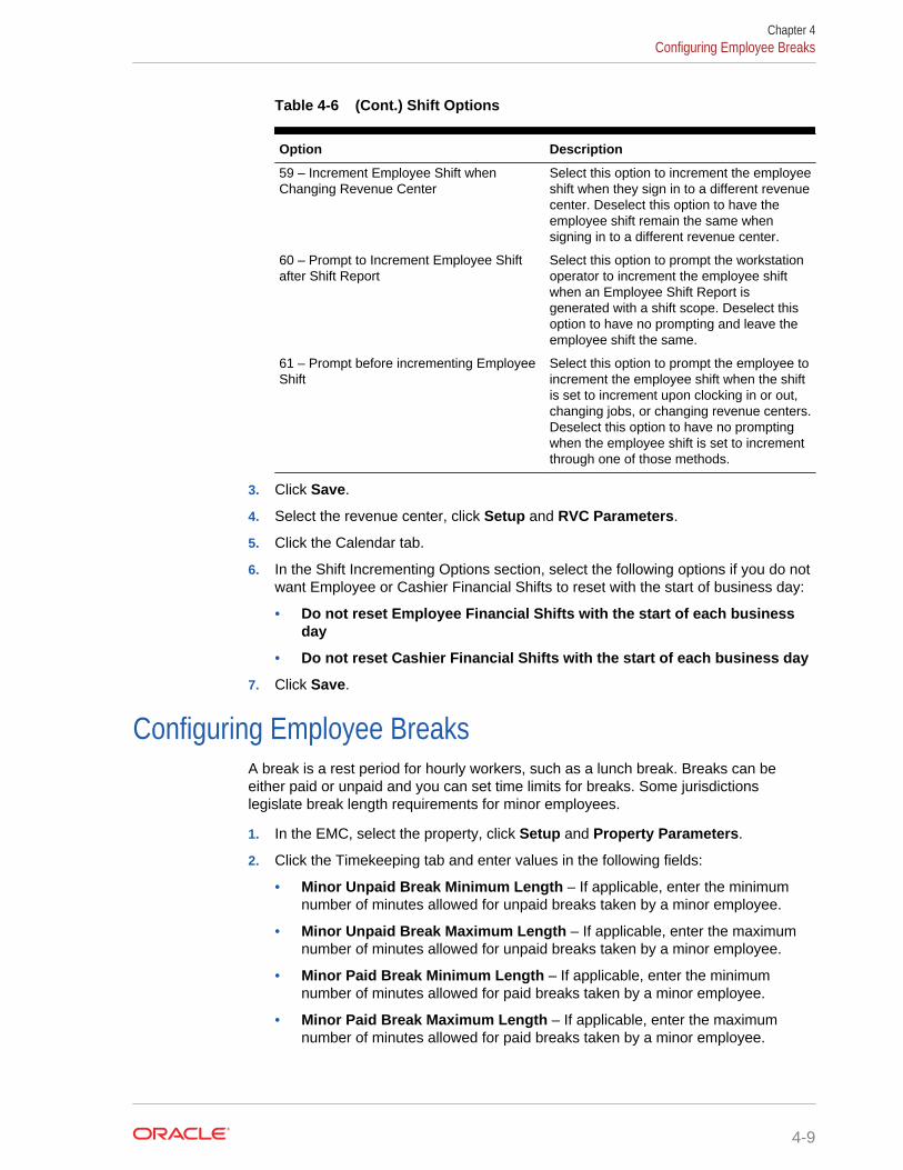
Table 4-6 (Cont.) Shift Options
Option Description
59 – Increment Employee Shift whenChanging Revenue Center
Select this option to increment the employeeshift when they sign in to a different revenuecenter. Deselect this option to have theemployee shift remain the same whensigning in to a different revenue center.
60 – Prompt to Increment Employee Shiftafter Shift Report
Select this option to prompt the workstationoperator to increment the employee shiftwhen an Employee Shift Report isgenerated with a shift scope. Deselect thisoption to have no prompting and leave theemployee shift the same.
61 – Prompt before incrementing EmployeeShift
Select this option to prompt the employee toincrement the employee shift when the shiftis set to increment upon clocking in or out,changing jobs, or changing revenue centers.Deselect this option to have no promptingwhen the employee shift is set to incrementthrough one of those methods.
3. Click Save.
4. Select the revenue center, click Setup and RVC Parameters.
5. Click the Calendar tab.
6. In the Shift Incrementing Options section, select the following options if you do notwant Employee or Cashier Financial Shifts to reset with the start of business day:
• Do not reset Employee Financial Shifts with the start of each businessday
• Do not reset Cashier Financial Shifts with the start of each business day
7. Click Save.
Configuring Employee BreaksA break is a rest period for hourly workers, such as a lunch break. Breaks can beeither paid or unpaid and you can set time limits for breaks. Some jurisdictionslegislate break length requirements for minor employees.
1. In the EMC, select the property, click Setup and Property Parameters.
2. Click the Timekeeping tab and enter values in the following fields:
• Minor Unpaid Break Minimum Length – If applicable, enter the minimumnumber of minutes allowed for unpaid breaks taken by a minor employee.
• Minor Unpaid Break Maximum Length – If applicable, enter the maximumnumber of minutes allowed for unpaid breaks taken by a minor employee.
• Minor Paid Break Minimum Length – If applicable, enter the minimumnumber of minutes allowed for paid breaks taken by a minor employee.
• Minor Paid Break Maximum Length – If applicable, enter the maximumnumber of minutes allowed for paid breaks taken by a minor employee.
Chapter 4Configuring Employee Breaks
4-9
• Regular Unpaid Break Minimum Length – Enter the minimum number ofminutes allowed for an unpaid break taken by a regular employee.
• Regular Unpaid Break Maximum Length – Enter the maximum number ofminutes allowed for an unpaid break taken by a regular employee.
• Regular Paid Break Minimum Length – Enter the minimum number ofminutes allowed for a paid break taken by a regular employee.
• Regular Paid Break Maximum Length – Enter the maximum number ofminutes allowed for a paid break taken by a regular employee.
3. Click Save.
Clock-In and Clock-Out CyclesA clock-in cycle for a workstation operator includes one clock in and the subsequentclock out. Clock-in cycles are sequentially numbered from the start of the currentpayroll period to the current date on employee time cards and labor detail reports. Ifbreaks are not in use, a cycle is the equivalent of a work shift.
A clock-in cycle includes the day, date, and time of the entry and the Job Code underwhich the employee clocks in.
Related Topics
• Setting Clock-In and Clock-Out Cycles
Setting Clock-In and Clock-Out Cycles1. In the EMC, select the Enterprise, property, or revenue center, click
Configuration and Employee Maintenance.
2. Search for the property employee record.
3. Select the Employee Records tab near the lower part of the screen, and thendouble-click the object number of the appropriate record.
4. If the ID field is blank, enter the employee identification number.
5. Click the Search/Table View tab.
6. Select the Property Employee Records tab near the lower part of the screen, andthen double-click the object number of the appropriate record.
7. Click the Job Codes tab and add a job code for the role if it does not exist.
Employees who clock in require a job code. Employees without a job codeassigned typically do not need to clock in (such as tax exempt employees). If anemployee has more than one job code assigned (for example, bartender andserver), the workstation prompts the employee to select a job code when clockingin.
8. Click Save to apply the changes.
9. Select the Enterprise level, click Configuration and Roles.
10. Select the role type, click the Operations tab and the Timekeeping sub tab.
11. In the Job Rate Options section, select the appropriate Clock in at Rate optionsfor employees associated with the role. Each rate number refers to a pay rate thatis assigned for the employee record.
Chapter 4Clock-In and Clock-Out Cycles
4-10

12. Select the appropriate general timekeeping options as described in the followingtable:
Table 4-7 Employee Timekeeping Options
Option Allow the Employee to Perform orAuthorize...
13 - Authorize/Perform Reprint of Time Card Reprinting a time card using the ReprintTime Card key, and to authorize non-privileged employees to do so
20009 - Authorize Clock In / Authorize ClockIn/Out for the Wrong Location
Other employees to clock in
Setting this option also allows users to clockin or out for the wrong location
20010 - Authorize/Perform Clock In/OutOutside Schedule or Scheduled Breaks
Clocking in or out at times that conflict withthe assignment in the Time Clock Schedulemodule
20011 - ON = Minor Employees; OFF =Regular Employees
Designate employees associated with therole as minors
20012 - Authorize/Perform Clock Out withOpen Checks
Clocking out at the end of a shift with openguest checks, and to authorize otheremployees to do so
20013 - Authorize Changing RevenueCenter at Clock In
Changing the revenue center assignment ofother employees who are clocking in
20014 - Change Revenue Center at Clock In Changing the revenue center assignmentwhen clocking in
20015 - Authorize/Perform Clock Out in theFuture
Clock themselves out at a time ahead of theapplication time
13. Click Save.
Related Topics
• Clock-In and Clock-Out Cycles
Job CodesA Job Code identifies a category of labor group (for example, Server, Bartender,Cashier, Manager) for timekeeping. Job codes:
• Link hourly employees to specific pay rates upon clock in
• Group labor hours and costs into job categories on reports
Related Topics
• Configuring Job Codes
Configuring Job Codes1. In the EMC, select the property, click Configuration and Job Codes.
2. Insert a new job code record with the appropriate name (for example, Server,Bartender, or Manager) and double-click it to open.
3. Select the Employee Role from the drop-down list to associate with the job code.
Chapter 4Job Codes
4-11

If you select 0 - None, the employee receives privileges based on the roles set inthe Employee Maintenance module.
This setting is ideal for an employee who has two job codes (for example, Serverand Bartender). The privileges associated with this employee role are active forthe duration of the clock-in cycle.
4. Select the Employee Class from the drop-down list.
If you select 0 - None, the employee uses the Employee Class set in theEmployee Maintenance module.
The employee is assigned to this employee class for the duration of the clock-incycle.
5. Select the Revenue Center in which the job code is available.
If you want to make the job code available in all revenue centers, select 0 - None.
6. Enter the Report Group for the job code.
The labor reports sort and calculate subtotals by the Report Group. If you set theReport Group to 0 (zero), the job code does not appear on job code reports.
7. Select the appropriate options as described in the following table:
Table 4-8 Job Code Options
Option Description
1 – Prompt for Direct Tips beforeClocking Out
Select this option to prompt employees who areclocked in under the job code to declare theamount of direct tips received (tips given directlyfrom the customer to the employee) whenclocking out.
2 – Prompt for Indirect Tips beforeClocking Out
Select this option to prompt employees who areclocked in under the job code to declare theamount of indirect tips received (tips given fromone employee to another) when clocking out.
3 – Cannot Clock Out with Open Checks Select this option to prevent employees clockedin under the job code from clocking out whilethey have open guest checks.
You can override this setting for employees thathave the Clock Out with Open Checksprivilege.
4 – Use Scheduled Time if EmployeeClocks in Early
Select this option to use the employee’sscheduled clock-in time for labor calculations ifthe employee clocks in earlier than scheduled.
5 – Prompt for Clock In Revenue Center Select this option to allow employees to selectthe revenue center when clocking in.
8. Click Save.
Related Topics
• Job Codes
Understanding Tip TrackingServers can use Tip Track to:
Chapter 4Understanding Tip Tracking
4-12

• Share tips with other employees
• Edit tip-outs
• Claim tips from other employees
Managers can use Tip Track to:
• Grant tip-out privileges
• Generate tip-out transaction reports
You cannot use Tip Track with Oracle Hospitality Labor Management.
Related Topics
• Configuring Tip Tracking and Reporting
• Configuring Tip Track Front of House Buttons
Configuring Tip Tracking and Reporting1. In the EMC, select the Enterprise level, click Configuration and Roles.
2. Select the type of role (for example, server or bartender).
3. Click the Operations tab and the Miscellaneous sub-tab.
4. If you want to allow employees to give cash tips to others, select 187 - Authorize/Perform the Pay Tip Out To Others Keys.
5. If you want to allow employees to receive a tip from another employee, select 188- Claim Tips From Other Employee.
6. If you want to allow employees to edit cash tips given to other employees, select189 - Authorize/Perform Edit Of Any Tip Outs.
7. Select the manager type of role in the left pane.
8. Click the Ad Hoc Reports sub-tab.
9. If you want to allow managers to run the Employee Tip Track Report, select 31045- Run Employee Tip Track Report.
10. Click Save.
11. Select the revenue center, click Setup and RVC Parameters.
12. Click the Options tab.
13. If you want to print a validation receipt when a tip-out or tip edit operation occurs,select 7 - Validate Employee Direct/Indirect Tips Declared Transactions.
14. Assign a validation printer at the property level:
a. Select the property, click Setup and Workstations.
b. Click the Printers tab.
c. Select a Validation Printer and click OK.
d. Click Save.
Related Topics
• Understanding Tip Tracking
Chapter 4Configuring Tip Tracking and Reporting
4-13

Configuring Tip Track Front of House Buttons1. In the EMC, select the Enterprise, property, revenue center, or zone, click
Configuration and Page Design.
2. Open the Front of House page on which to place tip track buttons.
3. On the Edit tab, select the page area in which to define the tip track functions.
4. Click Button.
5. On the General sub-tab, enter the button name Tip Track Tip Out in the Legendfield.
6. Select Function from the Type drop-down.
7. Click the black arrow directly beneath the Type drop-down, select Tips in the Typesection, select Tip Track Tip Out in the Results section, and click OK.
8. Repeat Steps 3 through 7 to create the following buttons:
• Tip Track Edit My Tips
• Tip Track Edit
9. Click Save.
Related Topics
• Understanding Tip Tracking
Chapter 4Configuring Tip Track Front of House Buttons
4-14

5Payments and Currency
Customers pay guest checks with various types of payments or tenders, ranging frompaper to plastic to digital.
• Types of Payment
• Configuring Base Currency and Alternate Currency
• Configuring Currency Conversions
• Configuring the Cash Tender
• Credit Card Tokenization
• Loadable Payment Card Configuration Tasks
• Loadable Payment Configuration Prerequisites
• Universal Transaction Gateway for Shift4
• Communication Methods for Fusebox Payment Card Driver
• stunnel Installation Methods
• Installing stunnel at a Single Host Location
• Installing stunnel Through Simphony as a CAL Package
• Configuring the CAPMS Payment Card Driver
• Configuring the CAPMS Payment Module
• Configuring the Dollars on the Net Payment Card Driver
• Configuring the Dollars on the Net Payment Module
• Configuring the Fusebox Payment Card Driver
• Configuring the Fusebox Payment Module
• Configuring the VisaD Payment Card Driver
• Configuring the VisaD Payment Module
• Configuring the Loadable Payment Card Device
• Creating Front of House Loadable Payment Card Buttons
• Distributing a Third-Party Credit Card Driver Package
• Copying Third-Party Payment Driver Files
• Creating a CAL Package for the Third-Party Payment Card Driver Distribution
• Credit Card Batching
• Creating a Credit Card Batch
• Editing a Credit Card Batch
• Settling a Credit Card Batch
• Credit Card Preamble
5-1
• Credit Card Preamble Rules
• Updating Standard Credit Card Preambles
• List of Standard Credit Card Preambles for the U.S.
• Pay at the Table
• Configuring a Credit Card Tender
• Configuring the Room Tender
• Configuring the OPERA PMS Payment Driver
• Configuring the MICROS Standard Credit Card Payment Module
• Configuring the Loadable PMS Payment Module
• Configuring the Demo Payment
• Setting the Front of House to Allow Pay at the Table
• Configuring Email Receipts
• Autosequence Events
• Configuring Autosequence Events
• Configuring the Autosequence Event Schedule
Types of PaymentPayments reduce the balance of the guest check, and can include the types listed inthe following table:
Table 5-1 Payment Types
Payment Type More Information
Cash Configuring the Cash Tender
Credit Cards Loadable Payment Card Configuration Tasks
Gift Cards Stored Value Configuration Tasks
Pay at the Table Pay at the Table
Hotel Room Charge Configuring the Room Tender
Configuring Base Currency and Alternate Currency1. In the EMC, select the Enterprise, property or zone, click Setup and Currency
Parameters.
2. Select the Base Currency from the drop-down list. This is the primary currency forthe location.
Oracle recommends setting the base currency once during initial configuration of aproperty, prior to opening guest checks. When you change the base currency afteropening checks, the Enterprise Management Console (EMC) prompts you forverification twice.
3. (Optional) Select the Alternate Currency from the drop-down list. This is the othercurrency used at the location. For example, a property located near Niagara Falls
Chapter 5Types of Payment
5-2

might set US Dollars as the base currency and accept Canadian Dollars as thealternate currency.
4. If you want to use rounding, select 4 - Round Currency. When you select thisoption the subsequent options are available. Select the appropriate options toround the amount due:
• 5 - ON = Round to Nearest 0; OFF = Round to Nearest 5 – Select thisoption if you want to round currency amounts to the nearest 0 (for example,163.336 rounds to 163.340). Deselect this option to round currency amountsto the nearest 5 (for example, 163.336 rounds to 163.335).
• 6 - ON = Round to Second-Least Significant Digit; OFF = Round to LeastSignificant Digit – Select this option if you want to round currency amountsbased on the second least significant digit (for example, in 100.45, the secondleast significant digit is 4). Deselect this option to round currency amountsbased on the least significant digit (for example, in 100.45, the least significantdigit is 5).
5. Click Save.
6. Select the Enterprise, property or zone, click Setup and Currency Availability.
7. If you selected the Enterprise level, for each record, select the non-base currency(foreign or alternate currency) in the Currency field.
8. Select the appropriate alternate currency options:
• 2 - Issue Change In Other Currency – Select this option if you want to issuechange from a currency conversion in the currency. Deselect this option toissue change in the base currency.
• 3 - Prompt For Issuing Change – Select this option to have the workstationprompt the workstation operator to issue change in the other currency.Deselect this option to issue change in the base currency.
• Select options 4, 5, and 6 as appropriate for the alternate currency. Theseoptions are described in Step 4.
9. Click Save.
Configuring Currency ConversionsYou can configure how one currency rate converts to another currency rate. Typically,currency conversion rates are set at the Enterprise level and each property receivesthe same conversion. If one location has a slightly different conversion rate for thesame two currencies, you can set the currency conversion at the zone (for example, aEuro-to-US Dollar conversion might be standard for the Enterprise level, but an airportproperty has a different rate).
1. In the EMC, select the Enterprise, property or zone, click Setup and CurrencyConversions.
2. Insert a record and double-click it. Each record contains two currencies: aCurrency and a Conversion Currency.
3. Select the Currency and click OK.
This field, divided by the Rate, determines the number of Conversion Currencyrecords.
Chapter 5Configuring Currency Conversions
5-3

4. Select the Conversion Currency and click OK. You must select a differentcurrency than the selection in the Currency field. That is, the Currency andConversion Currency fields cannot contain the same values.
This field, multiplied by the Rate, determines the number of Currency records.
5. Enter the conversion Rate.
The Rate determines how the application calculates the Currency and ConversionCurrency. The Conversion and Conversion Reverse fields calculate automaticallyto show additional information about the record.
6. Click Save.
Configuring the Cash TenderYou must configure a cash tender for guests to pay the check with cash.
1. In the EMC, select the Enterprise, property, or revenue center, click Setup andPayments.
2. Insert a record and enter Cash as the name.
3. Double-click the record to open it.
4. On the General tab, click the Import from a file link.
5. Browse to C:\MICROS\Simphony2\EgatewayService\handlers, selectMicros.Payment.Cash.dll, and click Open.
6. Click the Configuration tab.
7. In the Module Configuration sub-tab, enter information in the following fields:
Table 5-2 Module Configuration Fields
Field Description
Module ID Enter MicrosCashPaymentModule.
Description Enter a description for the payment driver (forexample, Micros Cash Payment Module).
Do Not Batch Select False.
Run As Service Select either True or False to indicate whetheryou want to run the Micros Cash Payment Modulemodule as a Service Host service. If you selectFalse, the cash module runs directly on Ops.
Show Change Due Dialog If you want to show a change due dialog in Ops,select True.
8. Click Save.
9. Select the Enterprise or property, click Configuration, and Tender/Media.
10. Insert a record and name it Cash.
11. Double-click the Cash record to open it.
12. On the General tab, in the Key Type field, select option 1 - Payment.
13. Click the Options tab, and the Printing Options sub-tab.
14. Select options 8 - Print Customer Receipt and 21 - Print Summary Totals.
Chapter 5Configuring the Cash Tender
5-4
15. Click Save.
Related Topics
• Adding Payment Keys to the Transaction Page
Credit Card TokenizationCredit card tokenization helps to protect merchants from credit card theft. Tokenizationtechnology replaces the customer’s credit card number with a different identifier touniquely distinguish the customer’s credit card during settlement of a transaction. Thistechnology eliminates the need to store credit card numbers on persistent media onthe merchant’s site. All sensitive information that is stored for credit card processing iskept off site.
Encryption technology is used to store customer credit card data. While the encryptiontechnology is secure, it requires ongoing maintenance tasks to maintain the security.Managing this technology can be cumbersome for merchants. Many smallermerchants do not typically employ Management Information System (MIS) staff tomonitor networks and security infrastructure. Larger Enterprise clients can incur largeauditing charges to verify that each property is compliant with Payment Card IndustryData Security Standards (PCI DSS).
In a typical restaurant payment scenario, a server picks up a guest check with thecredit card to be used for payment. The server swipes the credit card on the Point ofSale (POS) application and the credit authorization with the credit card number is sentto the credit card payment processor. The payment processor returns a validauthorization code and, along with the payment, a token is also returned to identify thecredit card during the transaction’s settlement. Any record of the original card number,expiration date, and track data is erased from memory. When the voucher prints, allthat remains is the last four digits of the original credit card number and a token thatidentifies the card to the payment processor for future operations.
Consider the same transaction, but with the network connection to the credit cardprocessor offline. In this case, the server must manually authorize the credit card andthe credit card payment processor cannot provide a token. The credit card data mustbe stored until a token can be acquired by the POS system (usually at transactionsettlement time). At that point the sensitive credit card information is purged from theapplication.
Table 5-3 Loadable Credit Card Tokenization
Loadable Credit Card Driver Requires Tokenization?
CAPMS Optional
Dollars on the Net by Shift4 Yes
Fusebox by Elavon Optional (Elavon sets tokenization)
VisaD No
Loadable Payment Card Configuration TasksSetting up a loadable payment driver consists of completing the tasks listed in thefollowing table:
Chapter 5Credit Card Tokenization
5-5

Table 5-4 Loadable Payment Card Configuration Tasks
Task More Information
Reading configuration prerequisites Configuration Prerequisites
(If applicable) Vendor installing third-partygateway application or communicationmethod
• Universal Transaction Gateway (requiredfor Dollars on the Net by Shift4)
• Communication Methods for FuseboxPayment Card Driver
Configuring the loadable payment driver Configuring the Payment Card Driver:• CAPMS• Dollars on the Net• Fusebox• VisaD
Configuring the payment device Configuring the Loadable Payment Device
Configuring the loadable payment cardmodule
Configuring the Payment Card Module:• CAPMS• Dollars on the Net• Fusebox• VisaD
Creating Front of House loadable paymentcard buttons
Creating Front of House Loadable PaymentCard Buttons
(Optional) Setting Automatic Event Tasks Autosequence Events
(If applicable) Distributing a third-partypayment card driver package
Distributing a Third-Party Credit Card DriverPackage
Related Topics
• Configuring the Dollars on the Net Payment Card Driver
• Configuring the Dollars on the Net Payment Module
Related Topics
• Installing stunnel at a Single Host Location
• Installing stunnel Through Simphony as a CAL Package
• Configuring the Fusebox Payment Card Driver
• Configuring the Fusebox Payment Module
Related Topics
• Configuring the CAPMS Payment Card Driver
• Configuring the CAPMS Payment Module
Related Topics
• Configuring the VisaD Payment Card Driver
• Configuring the VisaD Payment Module
Loadable Payment Configuration PrerequisitesBefore configuring the loadable payment card driver and module, perform the followingactions:
Chapter 5Loadable Payment Configuration Prerequisites
5-6

• Install Simphony version 2.6 or later at the property.
• Obtain access to the Enterprise Management Console (EMC) within Simphony.
• Ensure that you have the Value Added Reseller (VAR) sheet from a CAPMSpayment processing vendor representative. The VAR sheet contains the propertyinformation, such as the Bank Identification Number, Merchant Number, StoreNumber, and Terminal Number.
• (If Applicable) Implement custom payment or device drivers. The DistributingThird-Party Credit Card Driver CAL Packages section contains instructions.
Related Topics
• Configuring the Dollars on the Net Payment Card Driver
• Configuring the Dollars on the Net Payment Module
Related Topics
• Installing stunnel at a Single Host Location
• Installing stunnel Through Simphony as a CAL Package
• Configuring the Fusebox Payment Card Driver
• Configuring the Fusebox Payment Module
Related Topics
• Configuring the CAPMS Payment Card Driver
• Configuring the CAPMS Payment Module
Related Topics
• Configuring the VisaD Payment Card Driver
• Configuring the VisaD Payment Module
Universal Transaction Gateway for Shift4The Universal Transaction Gateway (UTG) is necessary for communication betweenSimphony and Dollars on the Net by Shift4. Obtain the Internet Protocol (IP) addressof each computer that processes credit card transactions, and provide this list to theShift4 representative. A Shift4 representative must install the UTG:
• On only one machine at a property. (Do not install UTG on each workstation.)
• Before you can configure the Shift4 loadable payment card driver in Simphony.
A Shift4 representative must also install and configure one instance of the UTG at theOracle Hospitality Hosting Center to support all batching activity. Depending on thetransaction volume, you can implement additional UTGs in the Hosting Center tohandle the required daily transactions.
UTG does not run on the Windows CE operating system.
Related Topics
• Configuring the Dollars on the Net Payment Card Driver
• Configuring the Dollars on the Net Payment Module
Chapter 5Universal Transaction Gateway for Shift4
5-7

Communication Methods for Fusebox Payment Card DriverYou can implement one of the following communication methods to process creditcards with the Fusebox payment card driver:
• Fusebox solution through stunnel
• ProtoBase Hosted Solution through Virtual Private Network (VPN)
For premise-based implementations, a single VPN can accommodate bothauthorization and settlement traffic.
Fusebox stunnel
The Fusebox application (Next Generation Hosted Solutions from Elavon) uses thestunnel application as a secure TCP connection between the property and the ElavonHosting Center. This secure connection allows credit card authorizations andcommunication between the Oracle Hospitality Hosting Center and the Elavon HostingCenter for settlements. Stunnel is a small application that uses a certificate to establishan SSL connection. You can implement stunnel through a Simphony CAL package. stunnel Installation Methods contains instructions about implementing stunnel.
ProtoBase Hosted Solution
If you use the legacy ProtoBase application, you need to use the ProtoBase HostedSolution VPN communication method. When you use the ProtoBase Hosted Solutionto communicate, establish at least two VPNs.
• Set the first VPN between the property and the ProtoBase Hosting Center. Installand configure a VPN appliance to establish the connection. This connection isused to process credit card authorizations. Contact an Elavon representative fordetails about this implementation.
• The second VPN appliance resides at the Oracle Hospitality Hosting Center and isused to process all settlements (batching) for the property. If multiple propertiesexist within an Enterprise organization, you can use a single VPN connection.Contact an Elavon representative for details about this implementation.
Related Topics
• Installing stunnel at a Single Host Location
• Installing stunnel Through Simphony as a CAL Package
• Configuring the Fusebox Payment Card Driver
• Configuring the Fusebox Payment Module
stunnel Installation MethodsSimphony uses the stunnel application to communicate with the Elavon HostingCenter. You can install stunnel on one computer (single host location) at theEnterprise level, or on individual workstations at the property to allow individualconnectivity to Fusebox by Elavon. You must install stunnel at the Oracle HospitalityHosting Center to perform all batching activities.
Chapter 5Communication Methods for Fusebox Payment Card Driver
5-8

Single Host Location
Use this method for Oracle Hospitality Hosting Center installations or for propertiesthat want to perform all payment card activity from a single computer. Installing stunnelat a Single Host Location contains instructions for this method.
CAL Package to Each Workstation
Use this method for properties that want to have stunnel installed on each workstationand perform payment card activity from multiple workstations. Installing stunnelThrough Simphony as a CAL Package contains instructions for this method.
Related Topics
• Installing stunnel at a Single Host Location
• Installing stunnel Through Simphony as a CAL Package
• Configuring the Fusebox Payment Card Driver
• Configuring the Fusebox Payment Module
Installing stunnel at a Single Host LocationObtain the Simphony version 2.6 or later installation media to perform the instructionsin this section.
1. From the root of the Simphony version 2.6 installation media, browse to \\Install\Simphony2\Tools\FuseboxSTunnel.
2. Double-click stunnel.exe. stunnel automatically installs the files under ProgramFiles, Fusebox, stunnel. stunnel installs as a service and is set to automaticallystart.
Related Topics
• Communication Methods for Fusebox Payment Card Driver
• stunnel Installation Methods
• Loadable Payment Card Configuration Tasks
• Loadable Payment Configuration Prerequisites
Installing stunnel Through Simphony as a CAL Package1. In the EMC, select the Enterprise level, click Setup and CAL Packages.
2. Select Fusebox STunnel in the navigation tree.
3. Click the Deployment Schedules tab.
4. Click Add Deployment.
5. Select 1 - Property/Enterprise in the Deployment Type drop-down list.
6. Select the property in the Property field.
7. Select 0 - Install in the Action to Take drop-down list.
8. Click Save.
Chapter 5Installing stunnel at a Single Host Location
5-9
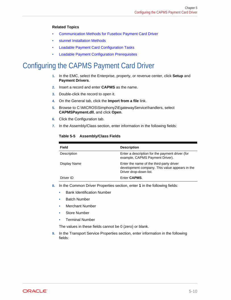
Related Topics
• Communication Methods for Fusebox Payment Card Driver
• stunnel Installation Methods
• Loadable Payment Card Configuration Tasks
• Loadable Payment Configuration Prerequisites
Configuring the CAPMS Payment Card Driver1. In the EMC, select the Enterprise, property, or revenue center, click Setup and
Payment Drivers.
2. Insert a record and enter CAPMS as the name.
3. Double-click the record to open it.
4. On the General tab, click the Import from a file link.
5. Browse to C:\MICROS\Simphony2\EgatewayService\handlers, selectCAPMSPayment.dll, and click Open.
6. Click the Configuration tab.
7. In the Assembly/Class section, enter information in the following fields:
Table 5-5 Assembly/Class Fields
Field Description
Description Enter a description for the payment driver (forexample, CAPMS Payment Driver).
Display Name Enter the name of the third-party driverdevelopment company. This value appears in theDriver drop-down list.
Driver ID Enter CAPMS.
8. In the Common Driver Properties section, enter 1 in the following fields:
• Bank Identification Number
• Batch Number
• Merchant Number
• Store Number
• Terminal Number
The values in these fields cannot be 0 (zero) or blank.
9. In the Transport Service Properties section, enter information in the followingfields:
Chapter 5Configuring the CAPMS Payment Card Driver
5-10

Table 5-6 Transport Service Properties Fields
Field Description
Batching Host Enter the IP address of the machine where thevendor gateway application is installed at theHosting or Enterprise level. Refer to the third partydriver development company for the appropriatevalue.
Batching Host Port Refer to the third party driver developmentcompany for the appropriate value.
Host Timeout Enter the timeout value in seconds. Setting thevalue to 0 (zero) equals no timeout. Do not leavethis field blank.
10. In the CAPMS Driver Properties section, enter information in the following fields:
Table 5-7 CAPMS Driver Properties Fields
Field Description
Enable RFID Select False.
Enable Shift4 Messaging Select True.
Enable Tokenization This setting is based on the vendor configuration.Select True to use tokenized messaging. SelectFalse to use standard non-tokenized messages.
Interface Name Refer to the third party driver developmentcompany for the appropriate value.
Message Version Refer to the third party driver developmentcompany for the appropriate value.
Non-Tokenized AuthorizationReversal Method
If you set Enable Tokenization to False, selectone of the following standard messaging options:• Expire – Do nothing with the authorization
reversal request.• Send – Send the authorization reversal
request.• ZeroSale – Send $0.00 sale as the
authorization reversal request.
Send Issue Number Select False.
Send Start Date Select False.
11. Click Save.
Related Topics
• Loadable Payment Card Configuration Tasks
• Loadable Payment Configuration Prerequisites
Configuring the CAPMS Payment Module1. In the EMC, select the Enterprise level, click Setup and Payments.
2. Insert a record and enter Credit Card as the name. If a Credit Card paymentrecord exists, skip this step.
Chapter 5Configuring the CAPMS Payment Module
5-11

3. Double-click the record to open it.
4. On the General tab, click the Import from a file link.
5. Browse to C:\MICROS\Simphony2\EgatewayService\handlers, selectMicros.Payment.LoadableCreditCardModule.dll, and click Open.
6. Select CAPMS from the Driver drop-down list.
7. Select the appropriate device from the Device drop-down list.
• Select Internal for Oracle Hospitality devices.
• Select the third-party device if the property is using a custom device driver.
8. Click the Configuration tab.
9. In the Common Properties section, enter information in the following fields:
Table 5-8 Common Properties Fields
Field Description
Allow Manual Authorization Credit Card This field indicates whether manualauthorization of credit cards is allowed.Select True for processors using theCAPMS driver.
Allow Partial Settlement On Batch Select False for processors using theCAPMS driver.
Do Not Batch This field indicates whether batch creationand settlement occurs within Simphony.Select False for processors using theCAPMS driver.
Encrypt Data Select True for processors using theCAPMS driver.
Manual Card Data Entry Retries This field indicates the number of times aworkstation operator can attempt tomanually enter a card number. OracleHospitality recommends entering 5. Theminimum value is 1.
Offline Authorizations This field indicates the number of offlinecard authorizations allowed before theapplication attempts to re-establish onlinecommunication.
Prompt for Manual Card Data Entry This field indicates whether workstationoperators can manually enter a cardnumber. Select True for processors usingthe CAPMS driver.
Retry Authorization Reversals On Batch Select False for processors using theCAPMS driver.
Run As Service Select False for processors using theCAPMS driver.
10. Click Save.
11. (Optional) If you need to configure CAPMS payment driver settings that are uniqueto the property or revenue center, continue with the following steps.
12. Select the property or revenue center, click Setup and Payment Drivers.
Chapter 5Configuring the CAPMS Payment Module
5-12

13. Double-click the CAPMS record to open it.
14. On the General tab, click the Override this record link, and then click Yes.
15. Click the Configuration tab.
16. If the property or revenue center values differ from those set at the Enterprise levelin the Common Driver Properties section, enter property information in the fields.
Ensure that you have the Value Added Reseller (VAR) sheet from a CAPMSpayment processing vendor representative. The VAR sheet contains the propertyinformation, such as the Bank Identification Number, Merchant Number, StoreNumber, and Terminal Number.
17. If the property or revenue center values differ from those set at the Enterprise levelin the Transport Service Properties section, enter property information in the fields.
18. Click Save.
Related Topics
• Loadable Payment Card Configuration Tasks
• Loadable Payment Configuration Prerequisites
Configuring the Dollars on the Net Payment Card Driver1. In the EMC, select the Enterprise, property, or revenue center, click Setup and
Payment Drivers.
2. Insert a record and enter DOTN as the name.
3. Double-click the record to open it.
4. On the General tab, click the Import from a file link.
5. Browse to C:\MICROS\Simphony2\EgatewayService\handlers, selectDOTNPayment.dll, and click Open.
6. Click the Configuration tab.
7. In the Assembly/Class section, enter information in the following fields:
Table 5-9 Assembly/Class Fields
Field Description
Description Enter a description for the payment driver (forexample, Dollars on the Net Payment Driver).
Display Name Enter the name of the third-party driver developmentcompany (for example, Shift4). This value appearsin the Driver drop-down list.
Driver ID Enter DOTN.
8. In the Common Driver Properties section, enter 1 in the following fields:
• Bank Identification Number
• Batch Number
• Merchant Number
• Store Number
Chapter 5Configuring the Dollars on the Net Payment Card Driver
5-13
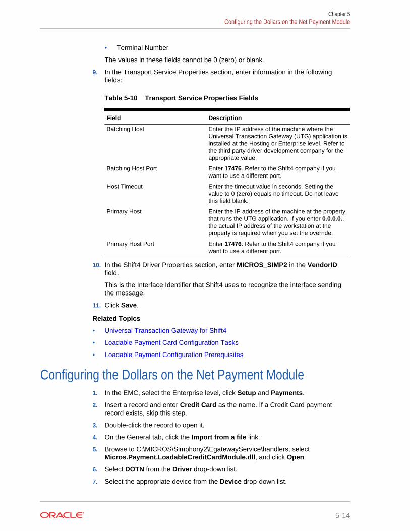
• Terminal Number
The values in these fields cannot be 0 (zero) or blank.
9. In the Transport Service Properties section, enter information in the followingfields:
Table 5-10 Transport Service Properties Fields
Field Description
Batching Host Enter the IP address of the machine where theUniversal Transaction Gateway (UTG) application isinstalled at the Hosting or Enterprise level. Refer tothe third party driver development company for theappropriate value.
Batching Host Port Enter 17476. Refer to the Shift4 company if youwant to use a different port.
Host Timeout Enter the timeout value in seconds. Setting thevalue to 0 (zero) equals no timeout. Do not leavethis field blank.
Primary Host Enter the IP address of the machine at the propertythat runs the UTG application. If you enter 0.0.0.0.,the actual IP address of the workstation at theproperty is required when you set the override.
Primary Host Port Enter 17476. Refer to the Shift4 company if youwant to use a different port.
10. In the Shift4 Driver Properties section, enter MICROS_SIMP2 in the VendorIDfield.
This is the Interface Identifier that Shift4 uses to recognize the interface sendingthe message.
11. Click Save.
Related Topics
• Universal Transaction Gateway for Shift4
• Loadable Payment Card Configuration Tasks
• Loadable Payment Configuration Prerequisites
Configuring the Dollars on the Net Payment Module1. In the EMC, select the Enterprise level, click Setup and Payments.
2. Insert a record and enter Credit Card as the name. If a Credit Card paymentrecord exists, skip this step.
3. Double-click the record to open it.
4. On the General tab, click the Import from a file link.
5. Browse to C:\MICROS\Simphony2\EgatewayService\handlers, selectMicros.Payment.LoadableCreditCardModule.dll, and click Open.
6. Select DOTN from the Driver drop-down list.
7. Select the appropriate device from the Device drop-down list.
Chapter 5Configuring the Dollars on the Net Payment Module
5-14
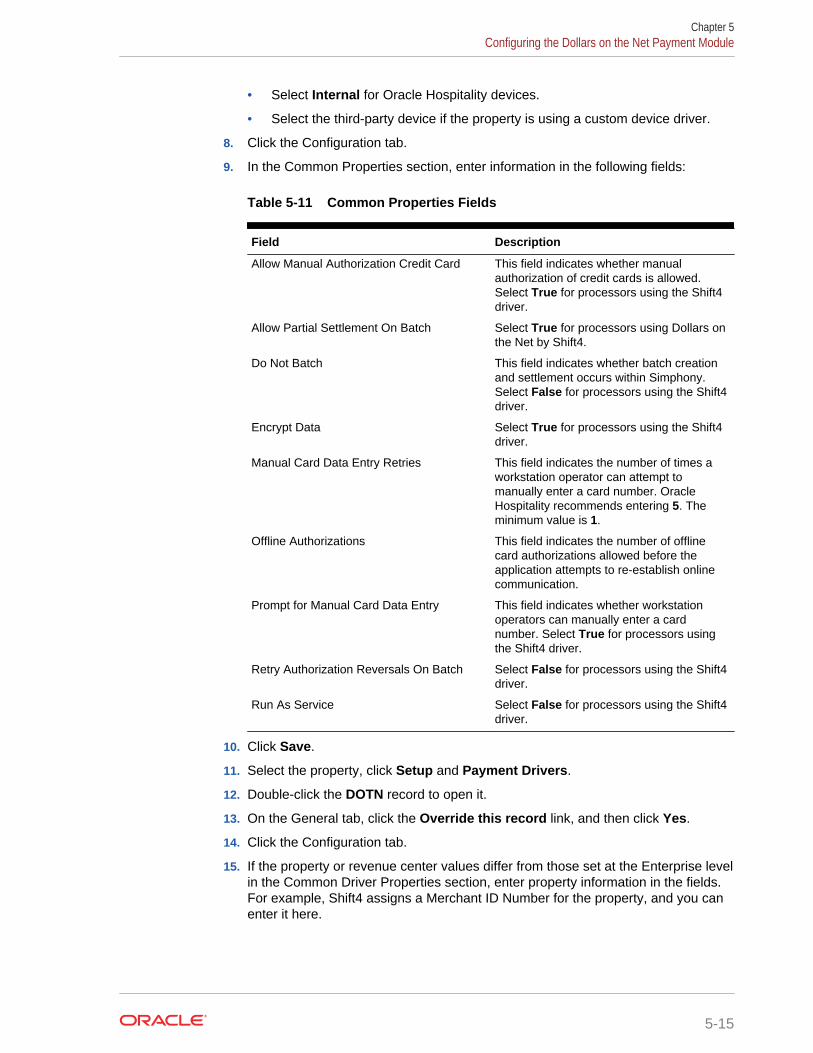
• Select Internal for Oracle Hospitality devices.
• Select the third-party device if the property is using a custom device driver.
8. Click the Configuration tab.
9. In the Common Properties section, enter information in the following fields:
Table 5-11 Common Properties Fields
Field Description
Allow Manual Authorization Credit Card This field indicates whether manualauthorization of credit cards is allowed.Select True for processors using the Shift4driver.
Allow Partial Settlement On Batch Select True for processors using Dollars onthe Net by Shift4.
Do Not Batch This field indicates whether batch creationand settlement occurs within Simphony.Select False for processors using the Shift4driver.
Encrypt Data Select True for processors using the Shift4driver.
Manual Card Data Entry Retries This field indicates the number of times aworkstation operator can attempt tomanually enter a card number. OracleHospitality recommends entering 5. Theminimum value is 1.
Offline Authorizations This field indicates the number of offlinecard authorizations allowed before theapplication attempts to re-establish onlinecommunication.
Prompt for Manual Card Data Entry This field indicates whether workstationoperators can manually enter a cardnumber. Select True for processors usingthe Shift4 driver.
Retry Authorization Reversals On Batch Select False for processors using the Shift4driver.
Run As Service Select False for processors using the Shift4driver.
10. Click Save.
11. Select the property, click Setup and Payment Drivers.
12. Double-click the DOTN record to open it.
13. On the General tab, click the Override this record link, and then click Yes.
14. Click the Configuration tab.
15. If the property or revenue center values differ from those set at the Enterprise levelin the Common Driver Properties section, enter property information in the fields.For example, Shift4 assigns a Merchant ID Number for the property, and you canenter it here.
Chapter 5Configuring the Dollars on the Net Payment Module
5-15

16. In the Transport Service Properties section Batching Host field, enter the IPaddress of the computer where the UTG application is installed at the HostingCenter.
17. In the Primary Host field, enter the IP address of the computer with the UTGapplication installed at the property.
18. In the Shift4 Driver Properties section, enter information in the following fields:
Table 5-12 Shift4 Driver Properties Fields
Field Description
APIPassword Shift4 assigns the password which is uniqueto the property and pairs it with theAPISerialNumber.
APISerialNumber Shift4 assigns the password which is uniqueto the property and pairs it with theAPIPassword.
ZipCode Enter the zip code of the property assignedby Shift4.
19. Click Save.
Related Topics
• Universal Transaction Gateway for Shift4
• Loadable Payment Card Configuration Tasks
• Loadable Payment Configuration Prerequisites
Configuring the Fusebox Payment Card Driver1. In the EMC, select the Enterprise, property, or revenue center, click Setup and
Payment Drivers.
2. Insert a record and enter Fusebox as the name.
3. Double-click the record to open it.
4. On the General tab, click the Import from a file link.
5. Browse to C:\MICROS\Simphony2\EgatewayService\handlers, selectFuseboxPayment.dll, and click Open.
6. Click the Configuration tab.
7. In the Assembly/Class section, enter information in the following fields:
Table 5-13 Assembly/Class Fields
Field Description
Description Enter a description for the payment driver (forexample, Fusebox Payment Driver).
Display Name Enter the name of the third-party driverdevelopment company (for example, Elavon). Thisvalue appears in the Driver drop-down list.
Driver ID Enter FB.
Chapter 5Configuring the Fusebox Payment Card Driver
5-16

8. In the Common Driver Properties section, enter 1 in the following fields:
• Bank Identification Number
• Batch Number
• Merchant Number
• Store Number
• Terminal Number
The values in these fields cannot be 0 (zero) or blank.
9. In the Transport Service Properties section, enter information in the followingfields:
Table 5-14 Transport Service Properties Fields
Field Description
Batching Host • If you are using the Fusebox solution, enter theIP address of the machine where the stunnelapplication is installed.
• If you are using ProtoBase, enter the IPaddress of the ProtoBase Hosted Solutionprovided by the Elavon representative forsettlement transactions.
Batching Host Port • Enter 10001 for Fusebox.• Contact the Elavon representative for the
ProtoBase Hosted Solution port number forsettlement transactions.
Host Timeout Enter the timeout value in seconds. Setting thevalue to 0 (zero) equals no timeout. Do not leavethis field blank.
Primary Host Enter the IP address of the machine that runs thestunnel application.• If stunnel is installed per workstation, enter
127.0.0.1.• If stunnel is installed on a single workstation at
the property, leave this field blank.• If the property is using ProtoBase, enter the IP
address of the ProtoBase Hosted Solutionprovided by the Elavon representative forauthorizations.
Primary Host Port • Enter 10001 for Fusebox.• Contact the Elavon representative for the
ProtoBase Hosted Solution port number forauthorizations.
10. In the Elavon Driver Properties section, enter information in the following fields:
Chapter 5Configuring the Fusebox Payment Card Driver
5-17
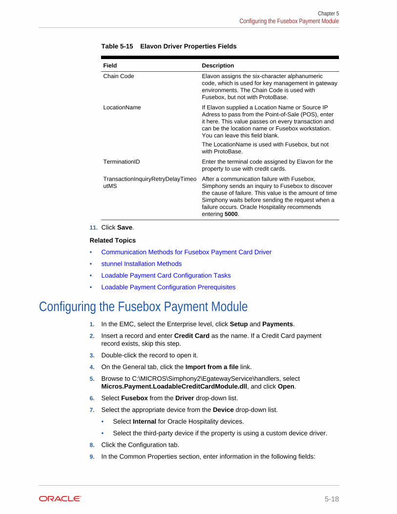
Table 5-15 Elavon Driver Properties Fields
Field Description
Chain Code Elavon assigns the six-character alphanumericcode, which is used for key management in gatewayenvironments. The Chain Code is used withFusebox, but not with ProtoBase.
LocationName If Elavon supplied a Location Name or Source IPAdress to pass from the Point-of-Sale (POS), enterit here. This value passes on every transaction andcan be the location name or Fusebox workstation.You can leave this field blank.
The LocationName is used with Fusebox, but notwith ProtoBase.
TerminationID Enter the terminal code assigned by Elavon for theproperty to use with credit cards.
TransactionInquiryRetryDelayTimeoutMS
After a communication failure with Fusebox,Simphony sends an inquiry to Fusebox to discoverthe cause of failure. This value is the amount of timeSimphony waits before sending the request when afailure occurs. Oracle Hospitality recommendsentering 5000.
11. Click Save.
Related Topics
• Communication Methods for Fusebox Payment Card Driver
• stunnel Installation Methods
• Loadable Payment Card Configuration Tasks
• Loadable Payment Configuration Prerequisites
Configuring the Fusebox Payment Module1. In the EMC, select the Enterprise level, click Setup and Payments.
2. Insert a record and enter Credit Card as the name. If a Credit Card paymentrecord exists, skip this step.
3. Double-click the record to open it.
4. On the General tab, click the Import from a file link.
5. Browse to C:\MICROS\Simphony2\EgatewayService\handlers, selectMicros.Payment.LoadableCreditCardModule.dll, and click Open.
6. Select Fusebox from the Driver drop-down list.
7. Select the appropriate device from the Device drop-down list.
• Select Internal for Oracle Hospitality devices.
• Select the third-party device if the property is using a custom device driver.
8. Click the Configuration tab.
9. In the Common Properties section, enter information in the following fields:
Chapter 5Configuring the Fusebox Payment Module
5-18

Table 5-16 Common Properties Fields
Field Description
Allow Manual Authorization Credit Card This field indicates whether manualauthorization of credit cards is allowed.Select True for processors using theFusebox driver.
Allow Partial Settlement On Batch Select False for processors using theFusebox driver.
Do Not Batch This field indicates whether batch creationand settlement occurs within Simphony.Select False for processors using theFusebox driver.
Encrypt Data Select True for processors using theFusebox driver.
Manual Card Data Entry Retries This field indicates the number of times aworkstation operator can attempt tomanually enter a card number. OracleHospitality recommends entering 5. Theminimum value is 1.
Offline Authorizations This field indicates the number of offlinecard authorizations allowed before theapplication attempts to re-establish onlinecommunication.
Prompt for Manual Card Data Entry This field indicates whether workstationoperators can manually enter a cardnumber. Select True for processors usingthe Fusebox driver.
Retry Authorization Reversals On Batch Select False for processors using theFusebox driver.
Run As Service Select False for processors using theFusebox driver.
10. Click Save.
11. (Optional) If you need to configure Fusebox payment driver settings that areunique to the property or revenue center, continue with the following steps.
12. In the EMC, select the property or revenue center, click Setup and PaymentDrivers.
13. Double-click the Fusebox record to open it.
14. On the General tab, click the Override this record link, and then click Yes.
15. Click the Configuration tab.
16. If stunnel is installed on a single workstation at the property, enter the PrimaryHost in the Transport Service Properties section. This is the IP address of themachine that houses stunnel for Fusebox, or the IP address for authorizations tothe ProtoBase Hosted Solution.
17. In the Elavon Driver Properties section, enter information in the following fields:
Chapter 5Configuring the Fusebox Payment Module
5-19

Table 5-17 Elavon Driver Properties Fields
Field Description
Chain Code Elavon assigns the six-characteralphanumeric code, which is used for keymanagement in gateway environments. TheChain Code is used with Fusebox, but notwith ProtoBase.
LocationName If Elavon supplied a Location Name orSource IP Adress to pass from the Point-of-Sale (POS), enter it here. This value passeson every transaction and can be the locationname or Fusebox workstation. You canleave this field blank.
The LocationName is used with Fusebox,but not with ProtoBase.
TerminationID Enter the terminal code assigned by Elavonfor the property to use with credit cards.
TransactionInquiryRetryDelayTimeoutMS After a communication failure with Fusebox,Simphony sends an inquiry to Fusebox todiscover the cause of failure. This value isthe amount of time Simphony waits beforesending the request when a failure occurs.Oracle Hospitality recommends entering5000.
18. Click Save.
Related Topics
• Communication Methods for Fusebox Payment Card Driver
• stunnel Installation Methods
• Loadable Payment Card Configuration Tasks
• Loadable Payment Configuration Prerequisites
Configuring the VisaD Payment Card Driver1. In the EMC, select the Enterprise, property, or revenue center, click Setup and
Payment Drivers.
2. Insert a record and enter VisaD as the name.
3. Double-click the record to open it.
4. On the General tab, click the Import from a file link.
5. Browse to C:\MICROS\Simphony2\EgatewayService\handlers, selectVisaDPayment.dll, and click Open.
6. Click the Configuration tab.
7. In the Assembly/Class section, enter information in the following fields:
Chapter 5Configuring the VisaD Payment Card Driver
5-20
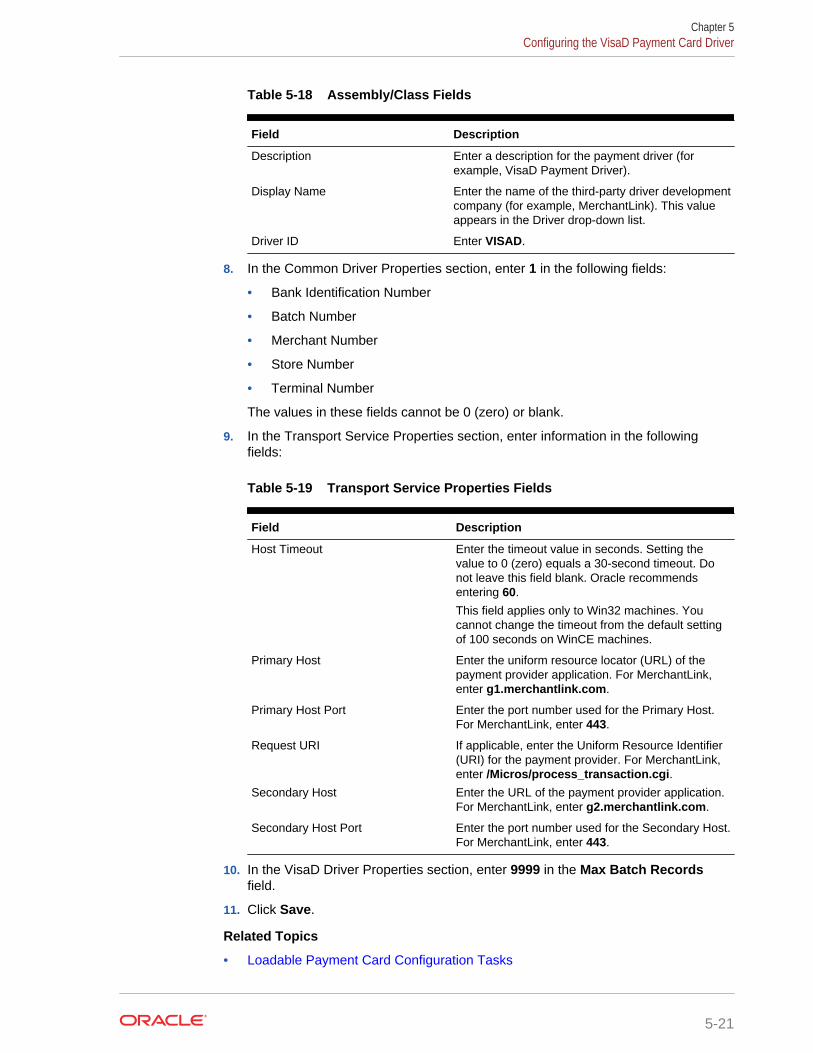
Table 5-18 Assembly/Class Fields
Field Description
Description Enter a description for the payment driver (forexample, VisaD Payment Driver).
Display Name Enter the name of the third-party driver developmentcompany (for example, MerchantLink). This valueappears in the Driver drop-down list.
Driver ID Enter VISAD.
8. In the Common Driver Properties section, enter 1 in the following fields:
• Bank Identification Number
• Batch Number
• Merchant Number
• Store Number
• Terminal Number
The values in these fields cannot be 0 (zero) or blank.
9. In the Transport Service Properties section, enter information in the followingfields:
Table 5-19 Transport Service Properties Fields
Field Description
Host Timeout Enter the timeout value in seconds. Setting thevalue to 0 (zero) equals a 30-second timeout. Donot leave this field blank. Oracle recommendsentering 60.
This field applies only to Win32 machines. Youcannot change the timeout from the default settingof 100 seconds on WinCE machines.
Primary Host Enter the uniform resource locator (URL) of thepayment provider application. For MerchantLink,enter g1.merchantlink.com.
Primary Host Port Enter the port number used for the Primary Host.For MerchantLink, enter 443.
Request URI If applicable, enter the Uniform Resource Identifier(URI) for the payment provider. For MerchantLink,enter /Micros/process_transaction.cgi.
Secondary Host Enter the URL of the payment provider application.For MerchantLink, enter g2.merchantlink.com.
Secondary Host Port Enter the port number used for the Secondary Host.For MerchantLink, enter 443.
10. In the VisaD Driver Properties section, enter 9999 in the Max Batch Recordsfield.
11. Click Save.
Related Topics
• Loadable Payment Card Configuration Tasks
Chapter 5Configuring the VisaD Payment Card Driver
5-21

• Loadable Payment Configuration Prerequisites
Configuring the VisaD Payment Module1. In the EMC, select the Enterprise level, click Setup and Payments.
2. Insert a record and enter Credit Card as the name. If a Credit Card paymentrecord exists, skip this step.
3. Double-click the record to open it.
4. On the General tab, click the Import from a file link.
5. Browse to C:\MICROS\Simphony2\EgatewayService\handlers, selectMicros.Payment.LoadableCreditCardModule.dll, and click Open.
6. Select VisaD from the Driver drop-down list.
7. Select the appropriate device from the Device drop-down list.
• Select Internal for Oracle Hospitality devices.
• Select the third-party device if the property is using a custom device driver.
8. Click the Configuration tab.
9. In the Common Properties section, enter information in the following fields:
Table 5-20 Common Properties Fields
Field Description
Allow Manual Authorization Credit Card This field indicates whether manualauthorization of credit cards is allowed.Select True for processors using the VisaDdriver.
Allow Partial Settlement On Batch Select False for processors using the VisaDdriver.
Do Not Batch This field indicates whether batch creationand settlement occurs within Simphony.Select False for processors using the VisaDdriver.
Encrypt Data Select True for processors using the VisaDdriver.
Manual Card Data Entry Retries This field indicates the number of times aworkstation operator can attempt tomanually enter a card number. OracleHospitality recommends entering 5. Theminimum value is 1.
Offline Authorizations This field indicates the number of offlinecard authorizations allowed before theapplication attempts to re-establish onlinecommunication.
Prompt for Manual Card Data Entry This field indicates whether workstationoperators can manually enter a cardnumber. Select True for processors usingthe VisaD driver.
Retry Authorization Reversals On Batch Select False for processors using the VisaDdriver.
Chapter 5Configuring the VisaD Payment Module
5-22

Table 5-20 (Cont.) Common Properties Fields
Field Description
Run As Service Select False for processors using the VisaDdriver.
10. Click Save.
11. (Optional) If you need to configure VisaD payment driver settings that are uniqueto the property or revenue center, continue with the following steps.
12. Select the property or revenue center, click Setup and Payment Drivers.
13. Double-click the VisaD record to open it.
14. On the General tab, click the Override this record link, and then click Yes.
15. Click the Configuration tab.
16. If the property or revenue center values differ from those set at the Enterprise levelin the Transport Service Properties section, enter property information in the fields.
Ensure that you have the Value Added Reseller (VAR) sheet from a VisaDpayment processing vendor representative. The VAR sheet contains the propertyinformation, such as the Agent Bank Number, Industry Type, Merchant Category,and Time Zone.
17. In the VisaD Driver Properties section, enter values in all fields based on the VARsheet information.
18. Click Save.
Related Topics
• Loadable Payment Card Configuration Tasks
• Loadable Payment Configuration Prerequisites
Configuring the Loadable Payment Card DeviceThe payment module generally uses payment devices containing internal drivers (forexample, magnetic stripe reader (MSR) or radio-frequency identification (RFID)) thatare compatible with Simphony and accept payment card information. If this is the case,skip the instructions in this section.
If the payment module uses a physical input device containing a custom driver that isnot supported with Simphony, you must configure the third-party device driver to allowcommunications between the device and Simphony.
1. In the EMC, select the Enterprise level, click Setup and Payment Device.
2. Insert a record and enter the device name.
3. Double-click the record to open it.
4. On the General tab, click the Import from a file link.
5. Browse to C:\MICROS\Simphony2\EgatewayService\handlers, select[ThirdPartyProvider].dll, and click Open.
6. Click the Configuration tab.
7. In the Assembly/Class section, enter information in the following fields:
Chapter 5Configuring the Loadable Payment Card Device
5-23
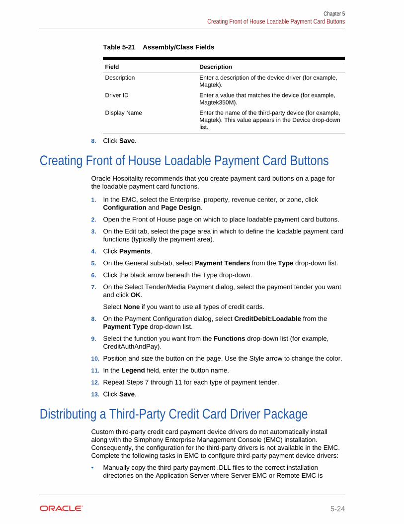
Table 5-21 Assembly/Class Fields
Field Description
Description Enter a description of the device driver (for example,Magtek).
Driver ID Enter a value that matches the device (for example,Magtek350M).
Display Name Enter the name of the third-party device (for example,Magtek). This value appears in the Device drop-downlist.
8. Click Save.
Creating Front of House Loadable Payment Card ButtonsOracle Hospitality recommends that you create payment card buttons on a page forthe loadable payment card functions.
1. In the EMC, select the Enterprise, property, revenue center, or zone, clickConfiguration and Page Design.
2. Open the Front of House page on which to place loadable payment card buttons.
3. On the Edit tab, select the page area in which to define the loadable payment cardfunctions (typically the payment area).
4. Click Payments.
5. On the General sub-tab, select Payment Tenders from the Type drop-down list.
6. Click the black arrow beneath the Type drop-down.
7. On the Select Tender/Media Payment dialog, select the payment tender you wantand click OK.
Select None if you want to use all types of credit cards.
8. On the Payment Configuration dialog, select CreditDebit:Loadable from thePayment Type drop-down list.
9. Select the function you want from the Functions drop-down list (for example,CreditAuthAndPay).
10. Position and size the button on the page. Use the Style arrow to change the color.
11. In the Legend field, enter the button name.
12. Repeat Steps 7 through 11 for each type of payment tender.
13. Click Save.
Distributing a Third-Party Credit Card Driver PackageCustom third-party credit card payment device drivers do not automatically installalong with the Simphony Enterprise Management Console (EMC) installation.Consequently, the configuration for the third-party drivers is not available in the EMC.Complete the following tasks in EMC to configure third-party payment device drivers:
• Manually copy the third-party payment .DLL files to the correct installationdirectories on the Application Server where Server EMC or Remote EMC is
Chapter 5Creating Front of House Loadable Payment Card Buttons
5-24

installed. Copying Third-Party Payment Driver Files contains instructions to copythe files to the appropriate directories.
• Create a Client Application Loader (CAL) Package in the EMC.
Related Topics
• Copying Third-Party Payment Driver Files
Copying Third-Party Payment Driver Files1. After you receive the CreditDriverPackage.zip from the third-party vendor, unzip it
to a location.
2. Copy the CreditCardDrivers2.0 folder from the \CreditDriverPackage\CE directoryand place it in the following folders on the Application Server:
• \MICROS\Simphony2\EgatewayService\CAL\WS5A\Packages
• \MICROS\Simphony2\EgatewayService\CAL\WS5\Packages
3. Copy the CreditCardDrivers2.0 folder from the \CreditDriverPackage\WIN32directory and place it in the following folder on the Application Server:
\MICROS\Simphony2\EgatewayService\CAL\Win32\Packages
4. Open the CreditCardDrivers2.0 folder in the \MICROS\Simphony2\EgatewayService\CAL\Win32\Packages directory and copy all of thefiles to the following directories on the Application Server, with the exception of theSetup.dat file. Do not copy the Setup.dat file to these directories.
• \MICROS\Simphony2\EgatewayService\handlers
• \MICROS\Simphony\EgatewayService\Download\EMCClient
5. Copy the correct third-party payment .DLL files to the appropriate installationdirectory on the Application Server where Server EMC or Remote EMC isinstalled.
• Server EMC
Copy custom .DLL files to \MICROS\Simphony2\EgatewayService\handlers
• Remote EMC
Copy custom .DLL files to \MICROS\EMC\EMCClient
Related Topics
• Distributing a Third-Party Credit Card Driver Package
• Creating a CAL Package for the Third-Party Payment Card Driver Distribution
Creating a CAL Package for the Third-Party Payment CardDriver Distribution
Create a Client Application Loader (CAL) package in the Enterprise ManagementConsole (EMC). See Understanding CAL Packages for instructions to create andupload the CAL package.
Chapter 5Copying Third-Party Payment Driver Files
5-25
Related Topics
• Copying Third-Party Payment Driver Files
Credit Card BatchingCredit card batches are typically created and settled automatically using a PCAutosequence during the Start of Day (SOD) process. You can manually create, edit,and settle credit card batches from the Enterprise Management Console (EMC) inspecial situations, such as:
• When the property wants to batch multiple times per day, at various times
• During troubleshooting
Related Topics
• Creating a Credit Card Batch
• Editing a Credit Card Batch
• Settling a Credit Card Batch
Creating a Credit Card Batch1. In the EMC, select a property, click Tasks and Create Batch.
2. (Optional) Enter information about the batch you are creating in the Commentfield.
3. If you want to create a batch for yesterday’s totals and all dates prior to yesterday,select Yesterday.
4. If you want to create a batch only for today’s totals up to the current time, selectCurrent Totals.
5. If you want to create a batch for the entire property, select All in the RevenueCenters section.
6. If you want to create a batch only for the totals of a particular revenue center,select Selected, and select a revenue center from the list.
7. If you want to revert the changes that you made and use the default selections,click Default.
8. Click Create.
Related Topics
• Credit Card Batching
Editing a Credit Card Batch1. In the EMC, select a property, click Tasks and Edit Batch.
2. Click Select adjacent to the Batch field, select a batch, and click Select.
3. If you want to refine the search results, use the Employee, Revenue Center,Card Holder, and Check Number filters.
Chapter 5Credit Card Batching
5-26
The card holder name is often encrypted on the card and is not stored in theTransaction database. Therefore, it is not always possible to use this as a searchparameter.
4. Click Search.
5. Click Edit near the relevant credit card record.
6. Make the changes, and click Save.
Related Topics
• Credit Card Batching
Settling a Credit Card Batch1. In the EMC, select a property, click Tasks and Transfer Batch.
2. Click Select, select one or more batches to transfer, and then click Transfer.
Related Topics
• Credit Card Batching
Credit Card PreambleA credit card preamble—sometimes called a credit card prefix, issuer identificationnumber (IIN), or bank identification number (BIN)—is a digit or series of digits at thebeginning of a credit card number that identifies the type of card or company thatissued the card.
• Credit Card Preamble Rules
Related Topics
• Updating Standard Credit Card Preambles
• List of Standard Credit Card Preambles for the U.S.
Credit Card Preamble RulesAdhere to the following rules that govern a valid credit card preamble:
• The Start and End preambles must end with an asterisk (*) (for example, 304*).
• The number of digits in the Start and End fields must be the same.
• The number of digits in the Start and End fields cannot exceed the Lengthdefined.
• The value of the End field must be greater than the value of the Start field.
• Credit Card Preamble
Related Topics
• Updating Standard Credit Card Preambles
• List of Standard Credit Card Preambles for the U.S.
Chapter 5Settling a Credit Card Batch
5-27
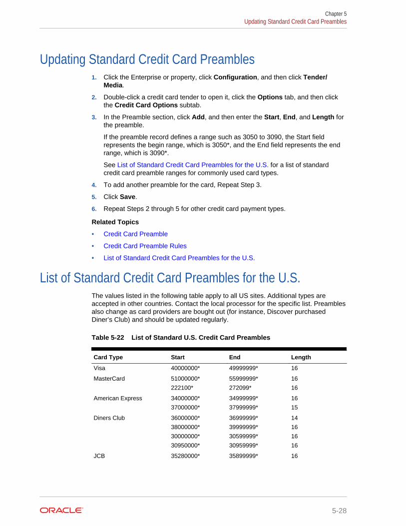
Updating Standard Credit Card Preambles1. Click the Enterprise or property, click Configuration, and then click Tender/
Media.
2. Double-click a credit card tender to open it, click the Options tab, and then clickthe Credit Card Options subtab.
3. In the Preamble section, click Add, and then enter the Start, End, and Length forthe preamble.
If the preamble record defines a range such as 3050 to 3090, the Start fieldrepresents the begin range, which is 3050*, and the End field represents the endrange, which is 3090*.
See List of Standard Credit Card Preambles for the U.S. for a list of standardcredit card preamble ranges for commonly used card types.
4. To add another preamble for the card, Repeat Step 3.
5. Click Save.
6. Repeat Steps 2 through 5 for other credit card payment types.
Related Topics
• Credit Card Preamble
• Credit Card Preamble Rules
• List of Standard Credit Card Preambles for the U.S.
List of Standard Credit Card Preambles for the U.S.The values listed in the following table apply to all US sites. Additional types areaccepted in other countries. Contact the local processor for the specific list. Preamblesalso change as card providers are bought out (for instance, Discover purchasedDiner’s Club) and should be updated regularly.
Table 5-22 List of Standard U.S. Credit Card Preambles
Card Type Start End Length
Visa 40000000* 49999999* 16
MasterCard 51000000*
222100*
55999999*
272099*
16
16
American Express 34000000*
37000000*
34999999*
37999999*
16
15
Diners Club 36000000*
38000000*
30000000*
30950000*
36999999*
39999999*
30599999*
30959999*
14
16
16
16
JCB 35280000* 35899999* 16
Chapter 5Updating Standard Credit Card Preambles
5-28

Table 5-22 (Cont.) List of Standard U.S. Credit Card Preambles
Card Type Start End Length
Discover 60110000*
60112000*
60117400*
60117700*
60118600*
64400000*
60110999*
60114999*
60117499*
60117999*
60119999*
65999999*
16
16
16
16
16
16
Discover (CUP) 62212600*
62400000*
62820000*
62292599*
62699999*
62889999*
16
16
16
Related Topics
• Credit Card Preamble
• Credit Card Preamble Rules
• Updating Standard Credit Card Preambles
Pay at the TableThis section describes the brief process in which a guest can pay a check using atablet device, and an overview for setting up Simphony’s Pay at the Table (PATT)features.
Guests can use PATT on the following handheld devices:
• Oracle MICROS Table E-Series
• Zebra MC40 (formerly the Motorola MC40) mobile device running on the Androidmobile operating system and configured with either an integrated or externalmagnetic card reader.
After a dining room guest or hotel guest places an order, a server or room service staffmember presents a tablet device containing the check to the guest, who can:
• View the check
• Add a tip or change the tip value
• Select a different language
• Share payment among several guests
• Charge menu items to a credit card or room account
• Swipe a credit card, or enter a room number and guest last name
• Sign the check with electronic signature after card authorization
• Enter a valid email address and receive a receipt electronically through email
When a guest charges payment to a room account, Simphony posts the total paymentto the OPERA property management system (PMS). The front desk manager can viewthe payment and signature from Pay at the Table in:
Chapter 5Pay at the Table
5-29

• Oracle Hospitality Reporting and Analytics using the Check Query and Audit andAnalysis portlets
• Oracle Hospitality Simphony Reports
Sales executives can demonstrate Pay at the Table features to clients without using amagnetic card or card reader.
Check images, including captured electronic signatures, are available through theOracle Hospitality Reporting and Analytics Check Query and Audit and Analysisportlets.
Complete the following tasks to set up the Pay at the Table feature.
• Configure the Tenders
• Configure the Payment Drivers
• Configure the Payment Modules
• Create Pay at the Table Buttons for Ops
• Configure Email Receipts
• Configure Languages
Related Topics
• Configuring a Credit Card Tender
• Configuring the Room Tender
• Configuring the OPERA PMS Payment Driver
• Configuring the MICROS Standard Credit Card Payment Module
• Configuring the Loadable PMS Payment Module
• Configuring the Demo Payment
• Setting the Front of House to Allow Pay at the Table
• Configuring Email Receipts
Configuring a Credit Card Tender1. In the EMC, select the Enterprise or property, click Configuration, and Tender/
Media.
2. Insert a record and name it based on the credit card company (for example, Visaor MasterCard).
3. Double-click the credit card record to open it.
4. On the General tab, in the Key Type field, select option 1 - Payment.
5. Click the Options tab, and the Printing Options sub-tab.
6. Select options 8 - Print Customer Receipt and 21 - Print Summary Totals.
7. Click the Ops Behavior sub-tab.
8. Select option 3 - Assume Paid in Full.
9. Click Save.
Chapter 5Configuring a Credit Card Tender
5-30

Related Topics
• Pay at the Table
Configuring the Room TenderConfigure a room charge tender for guests to charge meals to a hotel room usingOracle Hospitality OPERA.
1. In the EMC, select the Enterprise or property, click Configuration, and Tender/Media.
2. Insert a record and name it PATT Room Charge.
3. Double-click the PATT Room Charge record to open it.
4. On the General tab, in the Key Type field, select option 1 - Payment.
5. Click the Options tab, and the Interface Options sub-tab.
6. Select option 39 - Reverse PMS Itemizers On VOID Postings.
7. Click Save.
Related Topics
• Pay at the Table
Configuring the OPERA PMS Payment DriverTo configure the Oracle Hospitality OPERA 5 Hotel Property Systems payment driver:
1. In the EMC, select the Enterprise, property, or revenue center, click Setup andPayment Drivers.
2. Insert a record and enter OPERA PMS Driver as the name.
3. Double-click the record to open it.
4. On the General tab, click the Import from a file link.
5. Browse to C:\MICROS\Simphony2\EgatewayService\handlers, selectOperaWSPayment.dll, and click Open.
6. Click the Configuration tab.
7. In the Assembly/Class section, enter information in the following fields:
Table 5-23 Assembly/Class Fields
Field Description
Description Enter a description for the payment driver (forexample, PMS posting driver for OPERA).
Display Name Enter the name of the PMS driver (for example,OPERAPMS). This value appears in the Driverdrop-down list.
Driver ID Enter OPERAPMS.
8. In the Opera Interface Properties section, enter information in the following fields:
Chapter 5Configuring the Room Tender
5-31
Table 5-24 Opera Interface Properties Fields
Field Description
Connection String Enter jdbc / operaoperads.
Interface ID Enter the OPERA interface ID.
Opera Tender Number Enter the Tender/Media object number mapped forthe Room Charge.
Password Enter the password.
Resort Enter the name of the property using OPERA.
UserName Enter the user name.
Web Service Enter the uniform resource locator (URL) of theOPERA Web Service.
9. Click Save.
Related Topics
• Pay at the Table
Configuring the MICROS Standard Credit Card PaymentModule
1. In the EMC, select the Enterprise, property, revenue center, or zone, click Setupand Payments.
2. Insert a record and name it based on the payment driver you are using (forexample, MCreditDebit).
3. Double-click the record to open it.
4. Select 3 - DLL in the Content Type drop-down list.
5. Select the Import from a file link.
6. Browse to C:\MICROS\Simphony2\EgatewayService\handlers\Micros.Payment.MCreditDebit.dll, and click Open.
7. Click the Configuration sub-tab.
8. In the Assembly/Class section, enter information in the following fields:
Table 5-25 Assembly/Class Fields
Field Description
Module ID Enter a description for the payment driver (forexample,MicrosCreditDebitPaymentModuleStandard).
Description Enter a description for the payment driver (forexample, Micros Standard Credit/Debit PaymentDriver).
9. In the Common Properties section, enter information in the following fields:
Chapter 5Configuring the MICROS Standard Credit Card Payment Module
5-32

Table 5-26 Common Properties Fields
Field Description
Allow Manual Authorization CreditCard
This field indicates whether manual authorization ofcredit cards is allowed. Select True for processorsusing the MICROS standard credit and debitpayment driver.
Allow Partial Settlement On Batch Select False for processors using the MICROSstandard credit and debit payment driver.
Bank Identification Number Enter the 6-digit bank identification number providedby the bank or processor.
Batch Number Enter a value between 1 and 9999 to indicate thenext sequence number. The number increments byone each time a new batch is created, and resets to1 after reaching 999. The bank or processor assignsthe value for this field and uses it to detect duplicatebatches.
Do Not Batch This field indicates whether batch creation andsettlement occurs within Simphony. Select False forprocessors using the MICROS standard credit anddebit payment driver.
Encrypt Data Select True for processors using the MICROSstandard credit and debit payment module.
Host Timeout Enter the timeout value in seconds. Setting thevalue to 0 (zero) equals a 30-second timeout. Donot leave this field blank. Oracle Hospitalityrecommends entering 60.
This field applies only to Win32 machines. Youcannot change the timeout from the default settingof 100 seconds on WinCE machines.
Merchant Number Enter the merchant number provided by the bank orprocessor.
Offline Authorizations Enter the number of offline card authorizationsallowed before the application attempts to re-establish online communication.
Primary Host Enter the uniform resource locator (URL) of thepayment provider application. As an example, thisfield should include something.receiving-url.com.For MerchantLink, enter g1.merchantlink.com.
Primary Host Port Enter the port number used for the Primary Host.For MerchantLink, enter 443.
Prompt for Manual Card Data Entry This field indicates whether workstation operatorscan manually enter a card number. Select True forprocessors using the VisaD driver.
Retry Authorization Reversals OnBatch
Select False for processors using the MICROSstandard credit and debit payment module.
Run As Service Select False for processors using the MICROSstandard credit and debit payment module.
Store Number Enter the 4-digit store identification number used toidentify the merchant store. The bank or processorassigns the value for this field.
Terminal Number Enter the workstation number at the merchant store.
Chapter 5Configuring the MICROS Standard Credit Card Payment Module
5-33

Table 5-26 (Cont.) Common Properties Fields
Field Description
Manual Card Data Entry Retries This field indicates the number of times aworkstation operator can attempt to manually entera card number. Oracle Hospitality recommendsentering 5. The minimum value is 1.
VisaQ Compatibility Select False for processors using the MICROSstandard credit and debit payment driver.
10. If you are using the VisaD driver, enter information in the VisaD Driver Specificsection fields:
Table 5-27 VisaD Driver Specific Fields
Field Description
Agent Bank Number Enter a six-digit number that identifies the AgentBank Number. This value identifies the agent of theacquirer which signed the merchant. The acquirerprovides this value to the merchant.
Agent Chain Number Enter a six-digit number that identifies the AgentChain Number. This value identifies a specific chainof an agent organization. The merchant's bank orprocessor provides this number.
City Code The city code identifies the merchant’s location.Within the United States, enter the five- or nine-digitzip code of the merchant’s address. In othercountries, the bank or processor assigns the code.
Country Code Select the country that identifies where themerchant is located. The bank or processor assignsthe value for this field. The United States countrycode is 840.
Currency Code Select the currency that the merchant uses. Thebank or processor assigns the value for this field.The United States currency code is 840.
Enable Card Level Results Select True to have the the VisaD driver retrievecard-level results during authorization and return thedata at settlement.
Enable POS Data Code Select True to have the VisaD driver report the POSData Code at authorization and settlement.
Include Exp Date And Extra MagCard Data
Select True to include the expiration date andmodified magnetic stripe reader data duringsettlement.
Industry Type Select a value to identify the industry type to themerchant. The bank or processor assigns the valuefor this field.
Language Indicator This field is used to designate the language in whichAuthorization Response messages should bereturned to the workstation for display and printing.The bank or processor assigns the value for thisfield.
Chapter 5Configuring the MICROS Standard Credit Card Payment Module
5-34

Table 5-27 (Cont.) VisaD Driver Specific Fields
Field Description
Max Batch Records Enter the maximum number of records that can betransferred in one batch (for example, 9999). Somebanks and driver types can support only a specificnumber of records during credit card settlement.When you enter 0 (zero), all records are processedin the same batch.
Merchant Category Enter the four-digit number assigned by the bank orprocessor to identify the merchant type.
Merchant Location Enter the merchant location or city name providedby the bank or processor. For auditing purposes, theMerchant Location should correspond to thelocation or city that prints on a credit card voucher.
Merchant Name Enter the merchant’s name. For auditing purposes,the Merchant Name should correspond to the namethat prints on a credit card voucher.
Merchant State Enter the merchant’s state or province codeprovided by the bank or processor. For auditingpurposes, the Merchant State should correspond tothe state or province code that prints on a creditcard voucher.
Request URI If applicable, enter the uniform resource identifier(URI) to use when sending VisaD messages to theprocessor. For MerchantLink, enter /Micros/process_transaction.cgi.
Secondary Host Enter the uniform resource locator (URL) of thesecondary host. As an example, this field shouldinclude something.receiving-url.com. ForMerchantLink, enter g2.merchantlink.com.
Secondary Host Port Enter the port number used for the Secondary Host.For MerchantLink, enter 443.
Send RFID Data Select True to add RFID-related fields to themessage. Some processors require this informationto authorize and settle RFID transactions.
Time Zone Select the code used to calculate the local timewithin the VisaNet Authorization System. The bankor processor assigns the value for this field.
11. Click Save.
Related Topics
• Pay at the Table
Configuring the Loadable PMS Payment ModuleConfigure a property management system (PMS) payment module for guests tocharge meals to a hotel room using Oracle Hospitality OPERA version 5.0.04.01 andlater.
1. In the EMC, select the Enterprise, property, revenue center, or zone, click Setup,and Payments.
Chapter 5Configuring the Loadable PMS Payment Module
5-35

2. Insert a record and name it LoadablePMS.
3. Double-click the LoadablePMS record to open it.
4. Click the Import from a file link.
5. Browse to MICROS\Simphony2\EgatewayService\handlers\Micros.Payment.LoadablePmsModule.dll, and click Open.
6. Click the Configuration sub-tab.
7. Select the Module Functions section.
8. Enter the Configuration Number for the Room Charge tender record.
9. Select Payment as the Configuration Type.
10. Click Save.
Related Topics
• Pay at the Table
Configuring the Demo PaymentSales executives can use demo mode to demonstrate Pay at the Table features toclients without needing a magnetic card or reader.
1. In the EMC, select the Enterprise, property, revenue center, or zone, click Setupand Payments.
2. Insert a record for demo payments (for example, Demo).
3. Double-click the record to open it.
4. Select 3 - DLL in the Content Type drop-down list.
5. Click the Import from a file link.
6. Browse to C:\MICROS\Simphony2\EgatewayService\handlers\Micros.Payment.CreditDebit.dll, and click Open.
7. Click Save.
Related Topics
• Pay at the Table
Setting the Front of House to Allow Pay at the TableDepending on the property’s Pay at the Table (PATT) payment methods, you need tocreate the following PATT buttons for the Front of House page:
• PATT Credit Card – Create this button if the property allows credit card paymentswith PATT
• PATT Room Charge – Create this button if the property allows room charges withPATT
1. In the EMC, select the Enterprise, property, revenue center, or zone, clickConfiguration and Page Design.
2. Open the Front of House page on which to place Pay at the Table buttons.
Chapter 5Configuring the Demo Payment
5-36
3. On the Edit tab, select the page area in which to define the Pay at the Tablefunctions (typically the payment area).
4. Click Button.
5. On the General sub-tab, enter the button name in the Legend field.
6. Select Function from the Type drop-down.
7. Click the black arrow directly beneath the Type drop-down and select Pay at theTable.
8. Highlight the PATT button.
9. Click the Pay at the Table Config button.
10. (Optional) Select Enable Tip Screen, and enter the Default Tip Percent value.The tip percentage appears to the guest. If you do not want the tip screen toappear to guests, deselect Enable Tip Screen.
11. (Optional) Select Enable Share Payment and enter the Default Share Paymentgroup sizes (for example, 2, 3, 4). This is the default number of people that canshare the payment. (If a different number of people want to share payment, theguest can enter the number.) Deselect Enable Share Payment if you do not wantguests to share check payment.
12. (Optional) If you want to use Pay at the Table in demonstration mode, selectDemo Payment. This allows sales executives to demonstrate Pay at the Tablefeatures to clients without needing a magnetic card or reader. Deselect DemoPayment to use Pay at the Table live at a property.
13. In the Select Payment Type area, select the payment type (for example, CreditCard or OPERA) from the Payment Type drop-down.
14. Click the Edit Command link in the Command column.
15. In the Payment Configuration dialog, select the appropriate payment method fromType drop-down. Click Edit... and then enter the appropriate Command. Thefollowing table lists the Types and associated Commands.
Table 5-28 PATT Payment Methods
Type Command
Credit Card CreditDebit:MCreditDebit — MICROSstandard credit and debit drivers for creditcard charges
Credit Card Other CreditDebit:Loadable — Loadable creditand debit drivers for credit card charges
Opera Other1:LoadablePms — Loadable propertymanagement system driver for roomcharges
16. If the payment type is a credit card, select CreditAuthAndPay from theFunctions drop-down list, and click OK.
17. Position and size the button on the page. Use the Style arrow to change the color.
18. Click Save.
19. Repeat Steps 1 through 18 for each PATT button.
Chapter 5Setting the Front of House to Allow Pay at the Table
5-37
Related Topics
• Pay at the Table
Configuring Email Receipts1. In the EMC, select the property, click Setup andProperty Parameters.
2. On the General tab, click the Primary SMTP Server sub-tab.
3. Enter information in the fields as described in the following table:
Table 5-29 Email Receipt Fields
Field Description
Server Enter the email server or service to use.Click Select to choose from the SMTPServer list of commonly used mail servers(for example, Outlook, Gmail, or Yahoo).
Port Enter the port number for the SMTP emailserver. A default port of 587 works for mostSMTP servers.
SSL Select this option to require secure Internetcommunication.
User Name Enter the user name of the email addressthat will send receipts.
Password, Confirm Password Enter the password associated with theemail user name.
Source Email Enter the full email address to appear as thesender in the emailed receipt. Depending onthe SMTP server, this may not create a copyof emails sent.
Name Enter the business name or name to appearalong with the email in the sender field.Depending on the SMTP server, this valuemay or may not appear in the sent email (forexample, Username = jsmith Name = Johncould appear as:John<[email protected]>).
BCC List Enter the email address(es) to receive ablind carbon copy of the email receipt that issent to the guest. Oracle Hospitalityrecommends that you list the source emailin the BCC field so you can resend copies ofemail receipts later if necessary.
Send Test Email After saving the information entered in thefields, send a test email receipt message tothe source email address. A confirmationappears after the email is successfully sent.
4. Select Backup SMTP Server.
5. Configure the Backup SMTP Server with the same settings as the Primary SMTPServer or an alternate server from which to send emails in the event the primaryserver becomes unavailable.
Chapter 5Configuring Email Receipts
5-38
6. Select Text Formatting, and enter information in the following fields:
• Email Subject – Enter text in rich text format to appear as the subject line ofemail receipts.
• Email Body – Enter text in rich text format to appear as the body of emailreceipts. You must include @@Check in the body in order to send a copy ofthe receipt.
7. Select HTML Formatting, and enter information in the following fields:
• Email Subject – Enter text in HTML format as the subject line of emailreceipts.
• Email Body – Enter text in HTML format as the body of email receipts. Youmust include @@Check in the body in order to send a copy of the receipt.
8. Select the Send Html Email option to dim the Text Formatting tab, and send onlyHTML format. Deselect this option to dim the HTML Formatting tab and send onlythe text formatted email.
9. Click Save.
Related Topics
• Pay at the Table
Autosequence EventsYou can set up automatic event tasks, such as nightly credit card batching, using thePC Autosequence feature in Simphony. After you create an automatic event, you canschedule it to run repeatedly at specific frequencies or time intervals.
To set up an automatic event, you must configure the Autosequence Event and theAutosequence Event Schedule.
Related Topics
• Configuring Autosequence Events
• Configuring the Autosequence Event Schedule
Configuring Autosequence Events1. In the EMC, select the Enterprise level, click Configuration and PC
Autosequences.
2. Insert a record for the autosequence event (for example, Nightly Batch). If theautosequence event record exists, skip this step.
3. Double-click the record to open it.
4. On the General tab, select each Property to include in the autosequence eventrun.
5. (Optional) Select the employee group to have privileges to run the autosequenceevent from the Privilege Group drop-down list.
6. (Optional) To restrict execution of the autosequence event, click the Add link inthe Parameters section and add optional parameters.
7. Click the Steps tab.
Chapter 5Autosequence Events
5-39
8. Beneath the Steps section, click the Add link to add the first step of theautosequence event.
9. In the Step Parameters section, select the Step Type from the drop-down list.
10. Repeat Steps 9 and 10 to add each step required to run the autosequence event.
11. Select the outcome for each step:
• Step on Success – Select the step number to occur next if a step succeeds.For example, after Step 1 runs successfully, proceed to Step 2.
• Step on Failure– Select the step number to occur next if a step fails. Forexample, if Step 1 fails, do no proceed with any steps.
12. Click Save.
Related Topics
• Autosequence Events
Configuring the Autosequence Event Schedule1. In the EMC, select the Enterprise level, click Configuration and PC
Autosequence Schedules.
2. Insert a record for the autosequence schedule (for example, Nightly Batch). If theautosequence schedule record exists, skip this step.
3. Double-click the record to open it.
4. On the General tab, enter information in the following fields:
Table 5-30 General Settings Fields
Field Description
Autosequence Select the autosequence event from thedrop-down list.
Server Name Enter the name of the server located at theEnterprise level or Hosting Center.
Time Zone Select the time zone of the Enterprise levelor Hosting Center.
Schedule Type Select the frequency for the autosequenceevent.
Duration Select Enabled for the autosequence eventto run.
Select the Start and End dates for theautosequence event.
5. Click the Recurrence tab.
6. In the Daily section, enter the number of days for the autosequence event toreoccur. For example, to run the event daily, set this value to Every 1 day(s).
7. In the Daily Frequency section, set the time or times for the autosequence eventto run.
8. Click Save.
Chapter 5Configuring the Autosequence Event Schedule
5-40
Related Topics
• Autosequence Events
Chapter 5Configuring the Autosequence Event Schedule
5-41

6Taxes
A tax is a sum of money demanded by a government for its support or for specificfacilities or services, levied upon income, property, sales, and so on. The followingtable explains methods of taxation:
Table 6-1 Tax Methods
Tax Method Description
European Value Added Tax(VAT)
A VAT is a form of sales tax used in some countries. VAT isan inclusive tax, which means the tax is included in the menuitem price. The global tax type can be set as European orUnited States. A VAT tax is calculated differently, dependingon the global setting. In Europe, only inclusive type tax iscalculated. In the United States, inclusive type tax and add-ontype tax can be used at the same time.
U.S. Inclusive Tax U.S. inclusive tax uses the item price and a percent value tocalculate the tax amount. The tax is then included in the priceof each menu item not added to the bill.
For example, if the tax rate is 5% and the item price is $5.00,the inclusive tax method calculates by the formula: $5.00/(1+5%) = $4.76. The total price to the customerremains $5.00, but the net sales price is $4.76 and the taxis $0.24. If U.S. inclusive tax is used, only one inclusive taxrate may be applied to a menu item.
Add-on Tax This method uses the item price to calculate tax, which is thenadded to the bill.
For example, if the tax rate is 5% and the item is $5.00, theapplication calculates 5% of $5.00, posting $0.25 tax to thecheck and making the total due of $5.25.
Breakpoint or Threshold Tax Breakpoints establish the points at which an increase of onecent in sales will increase tax by one cent. For example, abreakpoint tax might be one percent for sales from zero totwenty cents and then two percent from twenty-one to fortycents. Twenty cents would be the breakpoint for this tax.
• Understanding Tax Rates and Tax Classes
• Serving Periods
• Configuring a Serving Period
• Order Types
• Configuring Order Types
• Configuring Order Types as Subtotal Keys
• Configuring Tax Rates and Classes
• Understanding Tax Labels
• Configuring Tax Labels
6-1
• Printing Tax Rate Per Item
• Configuring Tax Rates Per Item to Print on Guest Check, Customer Receipt andJournal
• Configuring Workstation Number and Transaction Number to Print on GuestCheck, Customer Receipt, and Journal
Understanding Tax Rates and Tax ClassesSimphony uses two tax handling files to assign taxes to menu items, discounts, andservice charges:
• Tax Rates
• Tax Classes
A tax class is a collection of tax rates. Tax classes determine the tax rates that applyto menu items and service charges, and which tax rates can be reduced by discounts.A tax class can have up to 64 active tax rates, but typically a single tax class has oneto three tax rates. By grouping multiple tax rates into a single tax class, you can easilysee a record named Food Tax in other Enterprise Management Console (EMC)modules without wondering which tax rates are active.
You can associate a tax class with the following types of records:
• Menu Item Class: All menu item definitions in the menu item class are taxed usingthe tax class
• Discount: Specific tax rates can receive a discount when a menu item isdiscounted
• Service Charge: Specific types of services charges are taxed, such as banquetand room service transactions
In some jurisdictions, multiple tax rates apply to food items. Usually these tax ratesmust be calculated separately for accounting purposes (allowing each jurisdictionalgovernment to collect the appropriate tax amount). Generally a restaurant must paytaxes to both the state and the city:
• State – 5% tax
• City – 2% tax
In this example, both the state and city tax rates are active for the Food tax class. Thetotal tax for a food item would be 7%.
For customer convenience, bars often use inclusive taxes. In some properties withmultiple revenue centers, it is common that a bar revenue center uses inclusive taxeswhile a restaurant revenue center uses add-on taxes, even though both revenuecenters serve the same items. In this scenario, the configuration of a Liquor tax classmight be:
• Inclusive tax rate – 5%
• Add-on tax rate – 5%
Using this scenario, you can set either order types or serving periods to have theappropriate tax rates in the revenue centers. The following table shows an exampleconfiguration using Order Types:
Chapter 6Understanding Tax Rates and Tax Classes
6-2

Table 6-2 Example of Inclusive Tax with Multiple Revenue Centers
Revenue Center Order Type Tax Configuration
Bar • Inclusive tax rate enabled• Add-on tax rate disabled
Restaurant • Inclusive tax rate disabled• Add-on tax rate enabled
Related Topics
• Configuring Tax Rates and Classes
Serving PeriodsA serving period is a time period during the business day in one revenue center. Thefollowing examples illustrate serving periods:
• Breakfast (5:00 a.m. to 11:00 a.m.)
• Lunch (11:00 a.m. to 5:00 p.m.)
• Dinner (5:00 p.m. to 10:00 p.m.)
You can run sales reports for serving periods, include the active serving period ininterface posting messages, and use serving periods on the default transactionscreen.
Related Topics
• Configuring a Serving Period
Configuring a Serving Period1. In the EMC, select the revenue center, click Configuration and Serving Periods.
2. Insert a record and name it for the serving period.
3. Select the serving period’s Start Time and End Time. If the serving period lasts allday, use the same start and end times.
4. In the Table Count field, enter the number of tables available during the servingperiod.
5. Select the days of the week when the serving period is active.
6. Select the Default Transaction Touchscreen to use when the serving period isactive.
7. If you are using Mobile MICROS workstation, select the MMH DefaultTransaction Touchscreen to use when the serving period is active.
8. Select the Default Main Level to use when the serving period is active.
9. Select the Default Sub Level to use when the serving period is active.
10. Click the Taxes tab.
11. Select the tax rates to use when the serving period is active.
12. Click Save.
Chapter 6Serving Periods
6-3

Related Topics
• Serving Periods
Order TypesAn order type is a menu item sales category, such as Dine In or Take Out. You can setup to eight order types for each location. Order types control active tax rates for atransaction and prevent theft in fast transaction environments. The following tabledescribes the three order type classes in Simphony:
Table 6-3 Order Types
Order Type Description
Transaction Order Type This is the order type of the current round. If the workstationoperator changes the transaction order type, the order type ofall menu items in the current round changes to the selectedorder type while the order type of the check remainsunaffected. A reference entry with the name of the changedorder type appears at the top of the menu items.
Check Order Type The check order type appears in the check detail header. If youselect 16 - Post to Check Order Type in the RVC Parametersmodule under Posting options, menu item sales post to thecheck order type. Otherwise, menu item sales post to theoverridden order type.
Menu Item Order Type This is the order type of the menu item and also affects thecondiments of the menu item. The workstation operator canchange the order type of an entire combo meal or selecteditems in a combo meal. A reference entry appears with thename of the order type beneath the menu item to which thechange was made. If the workstation operator consolidatesmenu items, changing the menu item order type affects allconsolidated items. When the workstation operator changes acondiment order type, it applies to the parent menu item.
Order Type Subtotal Security Option
In a fast transaction environment, you can increase security and prevent theft byrestricting the workstation operators’ ability to perform voids and cancel transactions,while still allowing operators to perform legitimate error corrections. Simphony allowsyou to suppress the check total on the workstation until the workstation operatorpresses a subtotal key. The following table describes the type of theft that can beprevented using the subtotal security.
Chapter 6Order Types
6-4
Table 6-4 Subtotal Restriction Scenarios
No Order Type Subtotal Keys Using Order Type Subtotal Keys
• Workstation operator begins transaction.• Customer orders hamburger and soda.• Workstation operator sees the total
as $4.78 and requests the paymentamount from the customer.
• The customer gives $4.78 in cash.• Workstation operator pockets the cash
and voids the items or cancels thetransaction.
• Workstation operator begins transaction.• Customer orders hamburger and soda.• Workstation operator does not see the
total amount due, and must press one ofthe Order Type function keys to view thesubtotal.
• The customer gives $4.78 in cash.• Workstation operator cannot void items or
cancel the transaction after pressing theOrder Type key. After pressing the OrderType key, the items ordered areconsidered previous-round items forvoiding purposes. Typically, onlymanagers can perform previous-roundvoids.
If the workstation operator adds anothermenu item after pressing the Order Typekey, the check summary is blank. Theworkstation operator can perform errorcorrections on items that were orderedsince the Order Type key was pressed,but cannot perform error corrections onitems before the Order Type declaration.
Related Topics
• Configuring Order Types
• Configuring Order Types as Subtotal Keys
Configuring Order Types1. In the EMC, select the Enterprise, property, or zone, click Descriptors and Order
Types.
2. In the Text field, enter an order type for each record (for example, Dine In, TakeOut, Drive Thru).
3. Click Save.
4. Select the Enterprise, property, revenue center, or zone, click Setup and OrderType Parameters.
5. For each order type record, select the appropriate options as described in thefollowing table:
Table 6-5 Order Type Options
Option Description
1 - Print on Customer Receipt andGuest Check
Select this option to print the order type name oncustomer receipts and guest checks.
Chapter 6Configuring Order Types
6-5

Table 6-5 (Cont.) Order Type Options
Option Description
2 - Print on Order Printer Select this option to print the order type name onorder printers.
4 - Do Not Post Transactions to TipReport Totals
Select this option if you do not want sales for theorder type to appear on Tip Report Totals.
5 - Perform Auto Combo Recognition Select this option to have workstationsautomatically perform auto combo recognition whenthe workstation operator changes the workstation tothe order type.
6 - Transaction Cancel Default Select this option when starting orders without anorder type.
If a workstation operator begins a transaction andcancels it before selecting an order type, Opsrequires the workstation operator to associate thecheck with an order type for posting purposes. Opsfinds the first order type that has this optionselected and uses it. When you deselect this option,Ops uses the first order type record in the list toassociate with the check.
8 - Enable Routing Order by OrderType
Select this option to control order routing by theorder type. The workstation order devices must beset for all possibilities and use this as an override todisable order devices.
6. In the Tax Mask field, select the appropriate tax rates for the order type record.
7. Select Active for each order type that you want to activate.
8. Click Save.
9. Select the revenue center, click Setup and RVC Parameters.
10. Select the Default Order Type from the drop-down list. This is the order type thatis active when a workstation operator begins a check.
11. Click Save.
12. If you want to override the default order type setting for a workstation:
a. Select the property, click Setup and Workstations.
b. Click the Transactions tab.
c. Select the Default Order Type from the drop-down list.
d. Click Save.
Related Topics
• Order Types
Configuring Order Types as Subtotal KeysYou can allow the Order Type keys in the revenue center to act as Subtotal keys.
1. In the EMC, select the Enterprise, property, or revenue center, click Setup andControl Parameters.
2. Click the Options tab.
Chapter 6Configuring Order Types as Subtotal Keys
6-6

3. If you do not want summary subtotals to appear on the workstation until theworkstation operator presses an Order Type key, select 8 - Display SummaryTotals Only After Order Type Declared.
4. Click Save.
Related Topics
• Order Types
Configuring Tax Rates and Classes1. In the EMC, select the Enterprise, property, or zone, click Setup and Tax Rates.
2. Locate the appropriate tax rate. There are up to 64 active tax rates.
3. In the Type field, select the tax rate type from the drop-down list. The followingtable describes the tax types:
Table 6-6 Tax Types
Type Description
0 - Disabled Tax Rate Select this option if you do not want to usethe tax calculation for the tax rate.
1 - Add On, Breakpoint Select this option to calculate the add-on taxusing the Breakpoint method, and add thetax to the check total.
The government imposing the tax provides abreakpoint chart to facilitate programmingthe breakpoint entry.
2 - Add On, Percentage Select this option to calculate the add-on taxusing the Flat Percentage Rate, and add thetax to the check total.
3 - Included, Percentage Select this option to calculate the inclusivetax using the Flat Percentage Rate todetermine what portion of the sales price isthe tax. The inclusive tax applies differentlydepending on the global tax type (Europeanor United States).
Because the tax is included in the price, thetax is backed out of gross sales on reports.You cannot back out inclusive tax from acheck total using an Exempt Tax functionkey.
4 - Florida Surcharge Select this option to calculate surcharges formenu items in Florida.
4. Click Save.
5. Select the Enterprise, property, or zone, click Setup and Tax Classes.
6. Insert a tax class record with the appropriate name (for example, Food Tax orLiquor Tax).
7. In the Taxes Enabled field, select the applicable tax rates and click OK. The taxrates you select are active for the tax class.
8. Click Save.
Chapter 6Configuring Tax Rates and Classes
6-7
Related Topics
• Understanding Tax Rates and Tax Classes
Understanding Tax LabelsSetting tax labels allows you to perform the following actions:
• Define up to two tax labels and associate each of them with a specific tax rate
• Associate multiple tax rates with the same tax labels
• Associate a blank tax label with tax exempt items (considered non-value-addedtax (VAT))
Related Topics
• Configuring Tax Labels
Configuring Tax Labels1. In the EMC, select the Enterprise, property, revenue center, or zone, click Setup
and Tax Parameters.
2. Click the International Options tab.
3. Select 17 - Enable Tax Labels.
4. Click the Options tab.
5. If you want to print items with a 0% tax rate on guest checks, select 8 - PostTaxable Sales when Tax Rate is Zero.
6. Click Save.
7. Select the Enterprise, property, revenue center, or zone, click Setup and FormatParameters.
8. Click the Options tab.
9. Select the appropriate printing options:
• 57 - Do Not Print Change/Payment Due in Double Wide – Select this optionif you do not want double-wide formatting when a guest check has changedue.
• 58 - Do Not Consolidate Current Round Items in Printed Guest Check –Select this option if you do not want to combine the current round items whenprinting a receipt.
10. Click Save.
Related Topics
• Understanding Tax Labels
Printing Tax Rate Per ItemYou can have a menu item’s tax rate print on the header of guest checks andcustomer receipts, and in the journal. The following diagram illustrates a samplecustomer receipt printed with the tax rates for each menu item, workstation numberand transaction number.
Chapter 6Understanding Tax Labels
6-8
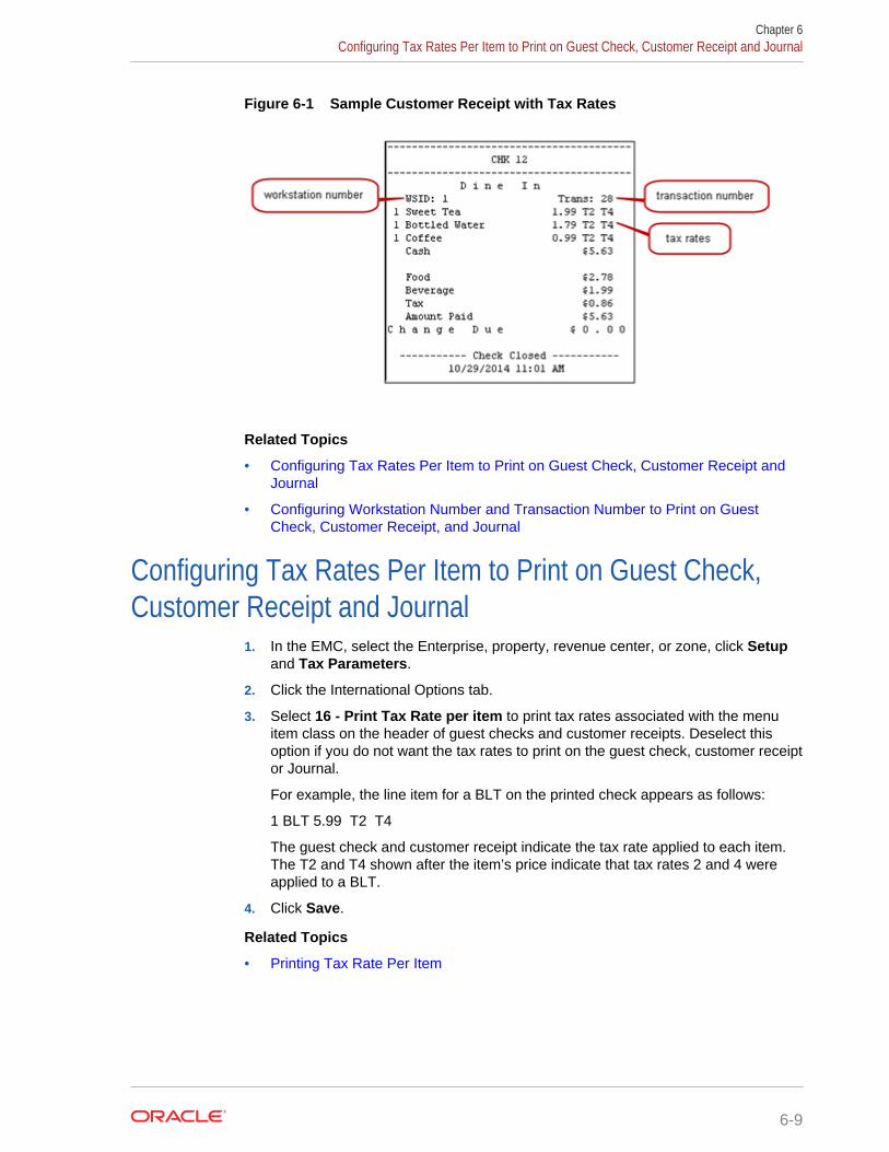
Figure 6-1 Sample Customer Receipt with Tax Rates
Related Topics
• Configuring Tax Rates Per Item to Print on Guest Check, Customer Receipt andJournal
• Configuring Workstation Number and Transaction Number to Print on GuestCheck, Customer Receipt, and Journal
Configuring Tax Rates Per Item to Print on Guest Check,Customer Receipt and Journal
1. In the EMC, select the Enterprise, property, revenue center, or zone, click Setupand Tax Parameters.
2. Click the International Options tab.
3. Select 16 - Print Tax Rate per item to print tax rates associated with the menuitem class on the header of guest checks and customer receipts. Deselect thisoption if you do not want the tax rates to print on the guest check, customer receiptor Journal.
For example, the line item for a BLT on the printed check appears as follows:
1 BLT 5.99 T2 T4
The guest check and customer receipt indicate the tax rate applied to each item.The T2 and T4 shown after the item’s price indicate that tax rates 2 and 4 wereapplied to a BLT.
4. Click Save.
Related Topics
• Printing Tax Rate Per Item
Chapter 6Configuring Tax Rates Per Item to Print on Guest Check, Customer Receipt and Journal
6-9

Configuring Workstation Number and Transaction Numberto Print on Guest Check, Customer Receipt, and Journal
1. In the EMC, select the Enterprise, property, revenue center, or zone, click Setupand Format Parameters.
2. Click the Options tab.
3. Select the appropriate workstation and transaction options. These options workindependently of each other; you can set one, both, or none.
• 54 - Print Workstation Number – Select this option to have the workstationnumber print on the header of guest checks and customer receipts, and in thejournal.
• 55 - Print Transaction Number – Select this option to have the transactionnumber print on the header of guest checks and customer receipts, and in thejournal. The journal header does not contain the legacy transaction number(labeled TRN).
4. Click Save.
Related Topics
• Printing Tax Rate Per Item
Chapter 6Configuring Workstation Number and Transaction Number to Print on Guest Check, Customer Receipt, and Journal
6-10

7Discounts
You can activate a discount using the methods described in the following table:
Table 7-1 Discount Methods
Discount Method Description
Manual A workstation operator manually applies a discount to acheck. This is a traditional discount method.
Automatic A workstation applies an automatic discount when thetransaction meets certain criteria. As a workstationoperator adds menu items to the guest check, theworkstation looks for items that trigger a discount, andthen applies the award amount to the check.
Coupon An automatic coupon discount is an automatic discountwith one difference: the workstation operator must firstapply the discount to the guest check, letting thediscount engine know that the discount is available forthe check.
Combination Pricing A combination pricing discount is a type of automaticdiscount or automatic coupon discount that allows aproperty to charge a single price for multiple items whenthey appear on a check at the same time. Restaurantsuse this type of discount in combo meal scenarios suchas Burger, Fries, and Soda are $3.25. Configuring aCombination Pricing Discount contains instructions toset up combination pricing discounts.
The discount engine within Ops automatically performs the following actions:
• Detects the presence of discountable menu items on a transaction.
• Applies the discounts to the transaction.
• Automatic Discounts
• Understanding Automatic Discount Rules
• Understanding Awarding Algorithms
• Discount Award Types
• Discount Exclusivity
• Simple Exclusivity
• Group Exclusivity
• Menu Item Groups
• Configuring Discount Privileges
• Configuring Discounts
• Understanding Automatic Discounts with Decimal Quantity Menu Items
7-1

• Amount Off Examples
• Amount Substitution Examples
• Configuring Decimal Quantity Menu Items
• Configuring a Combination Pricing Discount
• Applying Discounts Using Condiments
• Configuring the Condiment as the Trigger
• Configuring Parent Menu Item Class Discounts
• Configuring the Discount for a Condiment
• Creating the Discount Button
• Configuring Menu Item Groups
Related Topics
• Configuring Discounts
Automatic DiscountsThe workstation automatically applies discounts to a guest check based on conditionswithin the transaction and without workstation operator interaction. For example, aproperty may run a promotional sale: buy one DVD and receive one CD for free. In thissituation, whenever both a CD and a DVD appear on a single transaction, a 100%discount applies to the CD. There are several automatic discount types. This scenariois just one example of an automatic discount configuration.
Automatic discounts and automatic coupon discounts use the following Menu ItemGroups to determine which items receive a discount:
• Trigger Menu Item Group
A trigger menu item group contains at least one item that makes an item becomediscountable. For example, in a Buy a DVD, get a CD example, the DVD is in thetrigger menu item group.
• Award Menu Item Group
An award menu item group contains at least one item to receive a discount. Forexample, in the Buy a DVD, get a CD example, the CD is in the award menu itemgroup.
A menu item can be in both the trigger and award groups.
Simphony uses several other factors to determine the automatic discount amount:
• Automatic Discount Rules
• Awarding Algorithms
• Discount Award Types
• Discount Exclusivity
Chapter 7Automatic Discounts
7-2

Understanding Automatic Discount RulesVarious algorithms (known as Automatic Discount Rules) determine how Simphonycalculates a discount. The following table explains the Automatic Discount Rules:
Table 7-2 Automatic Discount Rules
Automatic Discount Rule Description
Item Price Substitution This discount rule is used in scenarios such as:• All Beverages are half-price on Tuesday• If you order three or more hamburgers, they are
20% off
The Item Price Substitution discount rule is similar to theSales Price rule.
Quantity Threshold This discount rule is used for Buy-One-Get-Onescenarios, such as Buy one DVD and get one CD for50% off, or Buy two entrees and a dessert is free.
Total Price Threshold This discount rule is used for scenarios such as 15% offall purchases of $200 or more.
Combination Pricing This discount type needs to have part of each itemincluded in the combination to apply the discount. Youmust order at least two of an item before a discount canbe applied. This discount rule is used for combinationmeals, such when a hamburger, fries, and soda areapplied on one check, charge $4.00.
Sales Price This discount rule is similar to Item Price Substitution,but it is simpler to program. Use this discount rule for Allhamburgers are $2.00 on Wednesdays, withoutconfiguring Minimum Quantity of trigger items or MaxCount per check.
Understanding Awarding AlgorithmsWhen dealing with automatic discounts, the better deal always wins. For example, ifyou set both Buy One DVD Get One CD For Free and Buy One DVD Get One Car ForFree, the application discounts the price of the car to $0.00 because this is a betterdeal than receiving a CD for $0.00.
When you use automatic discounts, the discount engine performs algorithms todetermine which discounts are applied and which items receive a discount. Thefollowing two types of algorithms determine the discount:
Chapter 7Understanding Automatic Discount Rules
7-3

Table 7-3 Awarding Algorithms
Awarding Algorithm Description
Best Deal for Customer Each automatic discount type provides the best deal forthe customer, which means that the workstation scansall menu items and determines the largest discount toapply. In this example, a common best deal scenario isdescribed as follows:• A combo discount is configured so any Pants-and-
Shirt purchase is $30.• If a customer orders a $25 pair of pants and a $20
shirt, the discount is $15:– $25 for a pair of pants, $20 for a shirt = $45– The combination price is $30, so the discount
is $15.• If the customer then orders a $25 shirt, the discount
recalculates:– $25 for a pair of pants, $25 for a shirt = $50– The combination price is $30, so the discount
is $20.
In this example, the higher-priced shirt is discounted, sothe customer receives a total discount of $20 instead ofjust $15. This is the calculation for all automaticdiscounts and you cannot configure it (except forQuantity Threshold Discounts). By default, Opsconsiders all menu items on the check and all discountsthat can apply, and creates the largest discount possiblefor the customer.
Best Deal for Merchant You can configure Quantity Threshold Discounts toprovide the best deal for the merchant, which meansthat the customer receives the lowest possible discount.Some jurisdictions require this configuration.
Figure 7-1 Examples of Best Deals for Merchant and Customer
Chapter 7Understanding Awarding Algorithms
7-4

Consider this discount: Buy one entree and get a second (of equal or lesser value) for50% off. The examples show the different calculations of the discount based on thebest deal configuration.
• In Example 1, the Filet is the most expensive item, so it is the trigger. The ChickenDinner is more expensive than the Spaghetti, so it is discounted by 50%. The totaldiscount is $7.50.
• In Example 2, the Filet is the most expensive item, so it is the trigger. TheSpaghetti is the least expensive entree, so it is discounted by 50%. The totaldiscount is $5.00.
Discount Award TypesThe following table describes the discount award types.
Table 7-4 Award Types
Award Type Description
Percent Off Simphony calculates this type of award as a percent ofthe sales total.
Amount Off Simphony calculates this type of award as a fraction ofthe sales total. The discount awarded cannot be greaterthan the Amount Off value.
Amount Off Examples contains examples of the AmountOff award type.
Amount Substitution Simphony calculates this type of award as a fraction ofthe sales total. Calculations do not change with wholenumbers. For decimal values, Simphony calculates whatpercent of the parent item the original substitution pricewas, and applies that percent discount to the newdecimal quantity.
Amount Substitution contains examples of the AmountSubstitution award type.
Discount ExclusivityDiscount exclusivity controls how multiple discounts interact with each other. You canconfigure discounts to be exclusive to the following:
• Per transaction
• Per menu item
• Based on workstation operator-defined groups
In short, discount exclusivity stops discounts from applying multiple times to the sameitems.
Discount exclusivity applies in these situations:
• A senior citizen discount coupon cannot be used at the same time as a 25% off allitems discount.
• A Buy One Get One Free discount cannot be applied to a transaction that also hasa Buy $100, Get 25% Off Discount.
Chapter 7Discount Award Types
7-5

• The customer's 10% coupon cannot be applied to items that get the Happy Hourdiscount.
You can configure two types of discount exclusivity: simple exclusivity and groupexclusivity. Simple exclusivity is easier to use and configure. Group exclusivity yieldsgreater flexibility, but at the price of complexity. Simple Exclusivity and GroupExclusivity contain more information about these types of discount exclusivity.
Automatic discounts always recalculate after the workstation operator adds orremoves an item from a guest check. Because of this, automatic discounts are alwaysapplied after manual discounts. Consider the following example:
• The revenue center is configured with automatic discounts enabled in the RVCParameters module.
• One automatic discount is active: all food is 10% off.
• A manual discount is configured, and it allows the 10% off all food discount to beon the check at the same time as the manual discount.
• The operator orders $20 of food.
• The automatic discount applies on the check for $2.
If the workstation operator then adds a manual discount for $5.00 off, the discountchanges:
• All automatic discounts are removed (this occurs internally on the workstation butis listed here to explain the logic)
• The check's total is $15.00 ($20.00 minus the $5.00 manual discount)
• The 10% automatic discount is applied for $1.50, taking the check's total to $13.50
Because of the scenario described here, it is not possible to get a better deal whencombining automatic and manual discounts. Either the discounts can both be on thecheck (as in this example) or the manual discount is not allowed (if the automaticdiscount is exclusive to the manual discount). Thus, if you want to use manualdiscounts and automatic discounts in the same environment, you should configure thediscounts that would normally be manual as automatic coupon discounts, which followthe best deal rules of the Discount Engine. See Understanding Awarding Algorithmsfor more information.
Configuring Discounts contains more information about setting the Simple ItemExclusivity and Simple Transaction Exclusivity options.
Simple ExclusivityThe following three discount options apply to simple exclusivity in the Discountsmodule:
Chapter 7Simple Exclusivity
7-6

Table 7-5 Simple Exclusivity Options
Option Description
9 - Simple Item Exclusivity When you select this option, only this discount can be appliedto a menu item. This prevents individual items from beingdiscounted more than once. Deselecting this option causesthe Exclusivity Group settings to determine how this discountinteracts with other discounts. If other discounts that are betterdeals can apply to the item or transaction, the better dealdiscounts apply.
23 - Simple TransactionExclusivity
When you select this option, only this discount can be appliedto a single check. This prevents the check from beingdiscounted more than once. Deselecting this option causesthe Exclusivity Group settings to determine how this discountinteracts with other discounts. If other discounts that are betterdeals can apply to the item or transaction, the better dealdiscounts apply.
24 - Discount is Final When you select this option, no additional discounts can beapplied to the transaction after this discount posts. (Thisoption works in automatic discount transactions only.)
Group ExclusivityGroup exclusivity is sometimes a difficult concept to grasp, but it is important as it letsyou configure the manner in which possibly hundreds of discounts interact. Anunderstanding of group exclusivity is crucial for long-term discount configuration.
When two discounts are exclusive to each other, it means that only one discountapplies. This exclusiveness can apply either per transaction or per menu item:
• If two discounts are transaction exclusive to each other, only one can be applied tothe same transaction. The discount that provides the best deal is applied to thecheck.
• If two discounts are item exclusive to each other, only one can be applied to aspecific menu item. Two discounts that are item exclusive can both be present ona transaction, but only applied to different menu items. Again, the discount thatprovides the best deal is applied to the item.
Table 7-6 Transaction Exclusivity
Discount In Exclusivity Group 1 In Exclusivity Group 2
A Yes Yes
B Yes No
C No Yes
D No No
Given the configuration shown in the Transaction Exclusivity table, the followingoccurs:
• Discounts A and B cannot appear on the same transaction because they bothbelong to the first group.
Chapter 7Group Exclusivity
7-7
• Discounts A and C cannot appear on the same transaction because they bothbelong to the second group.
• Discounts B and C can appear on the same transaction because they do notbelong to the same groups.
• Discount D can appear on any transaction with A, B, and C because it does notbelong to any group.
The Transaction Exclusivity example shows a configuration with only two groups. Thecombinations become more complex (yet more flexible) when using all 32 groups inthe property.
Table 7-7 Item Exclusivity
Discount In Exclusivity Group 1 Menu Items Affected byDiscount
A Yes x, y
B Yes x
C No y
Given the configuration shown in the Item Exclusivity table, the following occurs:
• Menu Item x is discounted by A or B, but not both. Discounts A and B areexclusive to each other.
• Menu Item y is discounted by A and C. These discounts are not exclusive to eachother, so they may both discount the same items.
Menu Item GroupsA menu item group is a workstation operator-defined group of menu items thatSimphony uses to calculate discounts. Within the Menu Item Group module, you canassign menu items based on Major Groups, Family Groups, or by menu item objectnumber or range.
Related Topics
• Configuring Menu Item Groups
Configuring Discount Privileges1. In the EMC, select the Enterprise level, click Configuration and Roles.
2. Select the role type, click the Operations tab and the Voids/Returns sub tab.
3. Select the appropriate options to allow employees to void discounts in a previousround and on closed checks:
• 27 - Authorize/Perform Void of Discounts from a Previous Round
• 70 - Authorize/Perform Void of Discounts on Closed Checks
4. Click the Transactions sub tab.
5. Select the appropriate options that apply to discounts:
• 20 - Post Discounts to Checks Belonging to Another Operator
Chapter 7Menu Item Groups
7-8

• 98 - Authorize/Perform Employee Meal Discount Override for Non-Scheduled Employees
6. Click Save.
Configuring Discounts1. In the EMC, select the Enterprise, property, or zone, click Configuration and
Discounts.
2. Insert a record for a discount or double-click a record to select it.
3. On the General tab, select the type of discount from the Activation Type drop-down list:
• 0 - Manual (Manually entered and applied) from the Activation Type
• 1 - Automatic (Automatically applied, operator cannot enter)
• 2 - Coupon (Automatically applied, operator must enter)
4. If you are configuring a manual discount, enter the following information.Otherwise, skip this step.
a. If you want to use a percent discount, enter the percentage in the Percentfield.
b. If you want to use an amount discount, enter the maximum amount allowed forthe discount in the Max Amount field.
5. Select Enabled to make the discount available to the workstation operator. (If youconfigure a temporary discount, you can quickly turn it off.)
6. Select the Tax Class to be discounted.
7. Select a Privilege Group to restrict the discount to only employees who are linkedto the same privilege group. Set the Privilege Group to 0 to allow all employeesto use the discount.
8. Select the method to determine how condiment menu items are discounted in theCondiment Discountability drop-down list.
9. Select the Report Group to associate with the discount.
10. Select the appropriate options for the discount. The following table describes theoptions and indicates the Activation Types (Manual, Automatic, Coupon) that areavailable for each option.
Table 7-8 Discount Options
Option Description Manual Automatic Coupon
1 - ON = Open;OFF = Preset
Select this option if you want tomake the discount open.
The workstation prompts theworkstation operator to enter theamount or percentage.
Yes No Yes
2 - ON =Amount; OFF =Percentage
Select this option if you want tomake the discount an amount.Deselect this option if you want thediscount to be a percentage.
Yes No No
Chapter 7Configuring Discounts
7-9
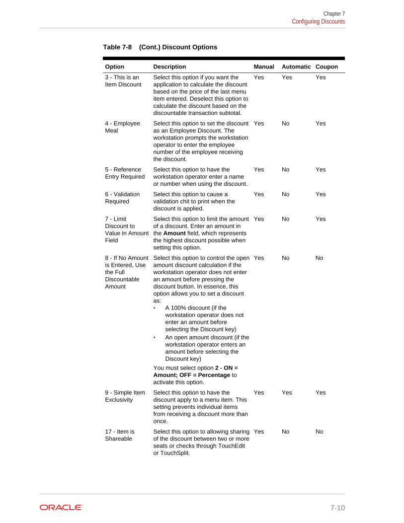
Table 7-8 (Cont.) Discount Options
Option Description Manual Automatic Coupon
3 - This is anItem Discount
Select this option if you want theapplication to calculate the discountbased on the price of the last menuitem entered. Deselect this option tocalculate the discount based on thediscountable transaction subtotal.
Yes Yes Yes
4 - EmployeeMeal
Select this option to set the discountas an Employee Discount. Theworkstation prompts the workstationoperator to enter the employeenumber of the employee receivingthe discount.
Yes No Yes
5 - ReferenceEntry Required
Select this option to have theworkstation operator enter a nameor number when using the discount.
Yes No Yes
6 - ValidationRequired
Select this option to cause avalidation chit to print when thediscount is applied.
Yes No Yes
7 - LimitDiscount toValue in AmountField
Select this option to limit the amountof a discount. Enter an amount inthe Amount field, which representsthe highest discount possible whensetting this option.
Yes No Yes
8 - If No Amountis Entered, Usethe FullDiscountableAmount
Select this option to control the openamount discount calculation if theworkstation operator does not enteran amount before pressing thediscount button. In essence, thisoption allows you to set a discountas:• A 100% discount (if the
workstation operator does notenter an amount beforeselecting the Discount key)
• An open amount discount (if theworkstation operator enters anamount before selecting theDiscount key)
You must select option 2 - ON =Amount; OFF = Percentage toactivate this option.
Yes No No
9 - Simple ItemExclusivity
Select this option to have thediscount apply to a menu item. Thissetting prevents individual itemsfrom receiving a discount more thanonce.
Yes Yes Yes
17 - Item isShareable
Select this option to allowing sharingof the discount between two or moreseats or checks through TouchEditor TouchSplit.
Yes No No
Chapter 7Configuring Discounts
7-10

Table 7-8 (Cont.) Discount Options
Option Description Manual Automatic Coupon
18 - EmployeeMeal DiscountApplies toScheduledEmployees Only
Select this option for propertiesusing timekeeping and only whensetting discount option 4 -Employee Meal.The discount can be used as anemployee meal discount only foremployees who are scheduled towork.
Yes No Yes
22 - EmployeeMeal DiscountApplies toEmployees OnBreak Only
Select this option for propertiesusing timekeeping and only whensetting discount option 4 -Employee Meal.The discount can be used as anemployee meal discount only foremployees who are on break.
Yes No Yes
23 - SimpleTransactionExclusivity
Select this option to have thediscount apply to a single check.This setting prevents the check fromreceiving a discount more thanonce.
Yes Yes Yes
24 - Discount isFinal
Select this option if you do not wantworkstation operators to applyadditional discounts to thetransaction after the discount isposted.
Yes Yes Yes
25 - DiscountCombo MealGroup Items
Select this option to discount combogroup menu items when the AllowDiscounts option is set for thecombo group.
Yes Yes No
28 - Apply toReturned orDirect-VoidedMenu Items
Select this option to allow thediscount to be applied to returnedand voided items.
No Yes Yes
29 - Menu itemto use checkopen time
Select this option if you want a menuitem to use the check’s open time(instead of using the current time) todetermine effectivity of the discount.
Yes Yes Yes
30 - Selectedmenu item toinclude parentmenu item indiscount
Select this option to include a parentmenu item in the discount when theworkstation operator selects a childmenu item for the discount.
Yes Yes Yes
Chapter 7Configuring Discounts
7-11

Table 7-8 (Cont.) Discount Options
Option Description Manual Automatic Coupon
31 - NetAutomaticService ChargeItemizer
Select this option if you want the netvalue of the menu item to post to theAutomatic Service Charge Itemizer,reducing the Automatic ServiceCharge after the discount is applied.
This option is available when you setoption 3 - This is an Item Discount(above) and option 12 - Add toAutomatic Service ChargeItemizer in the Menu Item Classesmodule.
No Yes Yes
32 - LimitDiscount valueto value ofDiscountableItem
Select this option to limit thediscountable amount to the item oraward when the Amount Offexceeds the item or award. Forexample, if the Amount Off is $5.00and the item or award is $4.00, thediscount is limited to $4.00.
Yes Yes No
33 - CashManagementTransaction Item
Select this option to include thediscount in Enterprise CashManagement (ECM) tracking andreports.
Yes No Yes
11. Click the RVC Type tab.
12. Select the revenue centers that can have the discount available.
13. Click the Effectivity tab.
14. Select the dates, days and times you want the discount to be in effect.
15. Click the Effectivity Groups tab.
The effectivity group configuration allows you to configure and packagepromotions so that the menu items and their discounts are only available for afixed period of time.
16. Click Add Effectivity Record.
17. Assign discounts, menu item prices, and other configuration elements to theeffectivity group.
18. Click Save.
19. If you want to set an automatic discount to apply to a revenue center:
a. Select the revenue center, click Setup and RVC Parameters.
b. Click the Options tab and select 48 - Enable Automatic Discounts byDefault. If you do not select this option, workstation operators must activateautomatic discounts per transaction using one of the following function keys:
• 655 - Auto Discount Toggle – Toggle the automatic discounts for thetransaction
• 656 - Auto Discount Apply – Apply all discounts possible
• 657 - Auto Discount Remove – Remove all discounts from thetransaction
Chapter 7Configuring Discounts
7-12
c. Click Save.
Related Topics
• Discounts
Understanding Automatic Discounts with Decimal QuantityMenu Items
Simphony ignores partial (or decimal) quantities with automatic discounts and appliesthe discount for the closest whole number. For example, if you have an order for 2.3cups yogurt, the automatic discount algorithms consider only 2.0 cups yogurt whendetermining whether to apply a discount.
• If you add a menu item to the check with an original quantity less than 1,Simphony does not apply the automatic discount.
• If you add a menu item to the check with a discount and then split the check, thediscount no longer applies to either check.
The following automatic discount rules ignore partial quantities when ordering:
• Quantity Threshold
• Combination Pricing
The discount engine ignores menu items added with an original quantity of less than 1(for example .5 cup of yogurt). Understanding Automatic Discount Rules containsmore information about Quantity Threshold and Combination Pricing.
Amount Off Examples contains examples of the Amount Off award type.
Amount Substitution contains examples of the Amount Substitution award type.
Related Topics
• Configuring Decimal Quantity Menu Items
• Configuring a Combination Pricing Discount
Amount Off ExamplesThis section provides examples of the Amount Off discount award type.
Example 1: Whole Number Item
• 1 Salad: $10.00
• Amount Off: $2.00
• Award Percent = Amount Off ($2.00) / Item Base Price ($10.00) = .20
• Discount = Current Sales Total ($10.00) x Award Percent (.20) = $2.00
Because the Current Sales Total is greater than or equal to the base price, thecustomer receives the Amount Off.
Example 2: Decimal Number Item
• .5 Salad: $5.00
Chapter 7Understanding Automatic Discounts with Decimal Quantity Menu Items
7-13
• Amount Off: $2.00
• Award Percent = Amount Off ($2.00) / Item Base Price ($10.00) = .20
• Discount = Current Sales Total ($5.00) x Award Percent (.20) = $1.00
When the Current Sales Total is less than the base price, the customer receives thediscount based on the award percent calculation.
Example 3: Decimal Number Item with Condiment
• .5 Salad: $5.00
• 1 Chicken: $5.00
• Current Sales Total = $10.00
• Discount = Current Sales Total ($10.00) x Award Percent (.20) = $2.00
Because the Current Sales Total is greater than or equal to the base price, thecustomer receives the Amount Off.
Related Topics
• Configuring Decimal Quantity Menu Items
• Configuring a Combination Pricing Discount
Amount Substitution ExamplesThis section provides examples of the Amount Substitution discount award type.
Example 4: Whole Number Item
• 1 Salad: $10.00
• Amount Substitution: $9.00 (discounted $1.00)
• Award Percent = Amount Substitution ($9.00) / Item Base Price ($10.00) = .90
• Discount = ($10.00) - Amount Substitution ($9.00) = $1.00
When dealing with whole number menu items, the customer always pays the AmountSubstitution. If the customer orders items totaling $100, they pay only $9.00.
Example 5: Decimal Number Item
• .5 Salad: $5.00
• Amount Substitution: $9.00 (discounted $1.00 from parent item base price)
• Award Percent = Amount Substitution ($9.00) / Item Base Price ($10.00) = .90
• Discount = (Current Sales Total – (Current Sales x Award Percent) = $5.00 –($5.00 x .90) = $5.00 – $4.50 = $.50
Example 6: Decimal Number Item, More Condiments Than Parent Items
• The Award Percent for Amount Substitution is based on the parent item baseprice, not the total price of each item plus condiments.
• The Discount Calculation only comes into effect when the menu item pluscondiments are less than the base price amount of the parent item.
Chapter 7Amount Substitution Examples
7-14

OrderNumber
Items Price AwardPercent
DiscountCalculation
DiscountAmount
CustomerPays
1 1 Salad $10.00 ($9.00) /($10.00) = .90
($25.00– $9.00)
$16.00 $9.00
1 Chicken $5.00
1 Steak $5.00
1 Steak
(This extracondimentis added tothe firstmenu item.)
$5.00
2 1 Salad $10.00 ($9.00) /($10.00) = .90
($25.00– $9.00)
$11.00 $9.00
1 Chicken $5.00
1 Steak $5.00
3 1 Salad $10.00 ($9.00) /($10.00) = .90
($17.50– $9.00)
$8.50 $9.00
1 Chicken $2.50
1 Steak $5.00
4 .5 Salad $5.00 ($9.00) /($10.00) = .90
($10.00– $9.00)
$1.00 $9.00
1 Steak $5.00
Related Topics
• Configuring Decimal Quantity Menu Items
• Configuring a Combination Pricing Discount
Configuring Decimal Quantity Menu Items1. In the EMC, select the Enterprise, property, or revenue center, click
Configuration and Menu Item Classes.
2. Double-click the menu item class record to open it.
3. On the General tab, select 2 - Decimal/fraction allowed, round sales count upin the Count Entry drop-down list.
4. Click the Options tab and select option 20 - Allow decimal quantity whenordering.
5. Click Save.
Related Topics
• Understanding Automatic Discounts with Decimal Quantity Menu Items
• Amount Off Examples
• Amount Substitution Examples
Configuring a Combination Pricing Discount1. In the EMC, select the Enterprise, property, or zone, click Configuration and
Discounts.
Chapter 7Configuring Decimal Quantity Menu Items
7-15

2. Double-click the discount record to open it.
3. On the Auto tab, select 4 - Combination Pricing from the Automatic(Automatically applied, operator cannot enter) drop-down list.
Table 7-9 Discount Rule Configuration Fields
Field Description
Priority This field determines the order in which theworkstation calculates the discounts. This field isblank (0) for all discounts by default, meaning thatthe workstation calculates discounts at the sametime. When using this field, the workstationcalculates all discounts in priority 1, then in priority2, and so on. the workstation calculates priority 0discounts last. The Priority field allows the discountengine to determine which discount to applyquicker, thus reducing central processing unit (CPU)time on the workstation.
Trigger MI Groups Select the menu item groups that belong to thiscombination discount. This discount is used inscenarios such as a Burger, Fries, and Sodaare $3.25. You can configure a maximum of fourtrigger Menu Item Groups for combination pricingdiscounts. You can use a Trigger MI Group morethan once (for example, if the combo meal includestwo sides). (This is not a typical configuration.)
Amount Substitution Enter the price to be charged for this combo meal.
Max Count Enter the maximum number of combo meals thatcan be ordered per check. In general, this field is setto 0 to allow an unlimited amount of combo mealson a single check.
4. Click Save.
Related Topics
• Understanding Automatic Discounts with Decimal Quantity Menu Items
• Amount Off Examples
• Amount Substitution Examples
Applying Discounts Using CondimentsYou can apply manual, automatic, and coupon discounts to a check when a condimentitem is present on the check. A workstation operator can manually apply a discount byselecting the condiment item. For example, configure a bagel to be a parent menuitem and configure the condiment, such as cream cheese, to trigger a 5% discount. Asa result, when the workstation operator enters the customer order for a bagel withcream cheese, the system applies the discount after the workstation operator selectscream cheese.
Place condiments in trigger menu item groups to have Simphony apply automatic andcoupon discounts.
Complete the following tasks to apply discounts using condiments:
Chapter 7Applying Discounts Using Condiments
7-16

• Specify the condiment to be the trigger
• Set the discount to apply to the parent menu item, condiment, or both
• Set up the discount for a condiment
• Create a discount button to appear on the workstation page
Related Topics
• Configuring the Condiment as the Trigger
• Configuring Parent Menu Item Class Discounts
• Configuring the Discount for a Condiment
• Creating the Discount Button
Configuring the Condiment as the Trigger1. In the EMC, select the Enterprise, property, or zone, click Configuration and
Menu Item Groups.
2. Create a menu item group record and then double-click it to open.
3. Click Add near the Include area.
4. Select information for the fields described in the following table:
Table 7-10 Include Fields
Field Description
Type Select 4 - By Menu Item.
Start # Click in this field, but do not enter a value.
End # Click in this field, but do not enter a value.
See Items and Select Click the link and then select the condiment to bethe trigger. This condiment appears in the End #field.
5. Click Save.
Related Topics
• Applying Discounts Using Condiments
Configuring Parent Menu Item Class Discounts1. In the EMC, select the Enterprise, property, or zone, click Configuration and
Menu Item Groups.
2. Double-click the menu item and select the Options tab.
3. Select 55 - Discounts Apply to Priced Condiments (parent items only) to allowboth parent and condiment items to receive the discount. Deselect option 55 if youwant only the parent item to receive the discount.
4. Click Save.
Chapter 7Configuring the Condiment as the Trigger
7-17

Related Topics
• Applying Discounts Using Condiments
Configuring the Discount for a Condiment1. In the EMC, select the Enterprise, property, or zone, click Configuration and
Discounts.
2. Create the discount record and then double-click it.
3. On the General tab, enter the fields as described in the following table:
Table 7-11 Discount Fields
Field Description
Activation Type Select the type of discount:• 0 - Manual (Manually entered and applied)• 1 - Automatic (Automatically applied, operator
cannot enter)• 2 - Coupon (Automatically applied, operator must
enter)
Percent Enter the discount percentage if you want to use a percentdiscount.
Max Amount Enter the maximum amount allowed for the discount if youwant to use an amount discount.
Enabled Select this option to make the discount available to theworkstation operator. (If you configure a temporarydiscount, you can quickly turn it off.)
Condiment Discountability Select the discount method for condiment menu items:• 0 - Use MI Class Option – You must also select
Menu Item Class option 55 - Discounts Apply toPriced Condiments (parent items only).
• 1 - Parent Items Only – Selecting this option makesthe discount apply only to the parent menu item.
• 2 - Condiment Items Only – Selecting this optionmakes the discount apply to the trigger condiment andto all condiments associated with the check.
• 3 - Parent and Highlighted Condiment Items – Thisoption is available only for manual discounts.
• 4 - Parent and All Condiment Items – Selecting thisoption makes the discount apply to the parent menuitem and to all condiments associated with the check.
Trigger MI Group Select the menu item group. This group is the trigger forthe discount. When you select 0 - Use DiscountItemizers, the only options available for the TriggerCondiment Group are 0 - None and all availablecondiment groups previously created.
Trigger Condiment Group Select the trigger condiment group. This field is dimmedwhen Trigger MI Group is set to 0 - Use DiscountItemizers.
Options Select 25 - Discount Combo Meal Group Items if youwant combo group menu items to be discounted. You mustalso select option 1 - Allow Discounts in the Combo MealGroups module.
Chapter 7Configuring the Discount for a Condiment
7-18

4. On the Effectivity tab, select the days on which the application applies thediscount.
5. On the RVC Type tab, select the revenue centers that can use this discount.
6. On the Menu Levels tab and in the Menu Level Configuration group, select alloptions for Active On Main Levels and Active On Sub Levels.
7. On the Output tab, select the following options:
• Print on Customer Receipt
• Print on Journal
• Print on Guest Check
8. Click Save.
Related Topics
• Applying Discounts Using Condiments
Creating the Discount Button1. In the EMC, select the Enterprise, property, or zone, click Configuration and
Page Design.
2. In the Type field, select Discount.
3. Click the black arrow beneath the Type field, select the discount, and click OK.
4. Click Save.
Related Topics
• Applying Discounts Using Condiments
Configuring Menu Item Groups1. In the EMC, select the Enterprise, property, or zone, click Configuration, and
Menu Item Groups.
2. Insert a menu item group record and then double-click it to open.
3. Click Add near one of the following areas:
• Include – You can add the menu item groups to include in the discount here
• Exclude – You can add the menu item groups to exclude from the discounthere
4. Select information for the fields described in the following table:
Chapter 7Creating the Discount Button
7-19
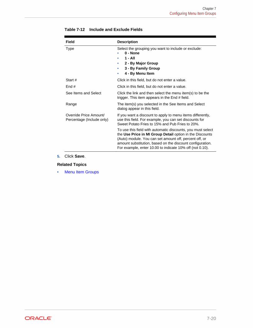
Table 7-12 Include and Exclude Fields
Field Description
Type Select the grouping you want to include or exclude:• 0 - None• 1 - All• 2 - By Major Group• 3 - By Family Group• 4 - By Menu Item
Start # Click in this field, but do not enter a value.
End # Click in this field, but do not enter a value.
See Items and Select Click the link and then select the menu item(s) to be thetrigger. This item appears in the End # field.
Range The item(s) you selected in the See Items and Selectdialog appear in this field.
Override Price Amount/Percentage (Include only)
If you want a discount to apply to menu items differently,use this field. For example, you can set discounts forSweet Potato Fries to 15% and Pub Fries to 20%.
To use this field with automatic discounts, you must selectthe Use Price in MI Group Detail option in the Discounts(Auto) module. You can set amount off, percent off, oramount substitution, based on the discount configuration.For example, enter 10.00 to indicate 10% off (not 0.10).
5. Click Save.
Related Topics
• Menu Item Groups
Chapter 7Configuring Menu Item Groups
7-20

8Service Charges
A service charge is the amount added to a sales transaction for a service renderedand is posted to one of the following parties:
• The person or people providing the service (for example, a server or bartender, ora team of servers)
• The House or the establishment providing the service
You can configure the following types of service charges:
• Service changes that report as Tips on employee tip reports
• Service changes that report as Service Charges on employee tip reports
• Service changes that are paid to the House
• Non-revenue service charges
• Gift certificates sold
• Configuring Service Charges
Related Topics
• Configuring Service Charges
Configuring Service Charges1. In the EMC, select the Enterprise, property, or zone, click Configuration and
Service Charges.
2. Insert the service charge record and then double-click it.
3. On the General Settings tab, enter the fields as described in the following table:
Table 8-1 General Settings Fields
Field Description
Percent Enter the service charge percentage.
Amount Enter the service charge amount.
Tips Paid Tender/Media If you want to link a tender to the service charge, selectthe Tender/Media from the drop-down list.
HALO Enter the High Amount Lock Out (HALO) value for theservice charge. This field prevents workstationoperators from entering abnormally high values for theservice charge. To exceed this limit, the workstationoperator must have the Authorize/Perform OverHALO Amounts on Service Charge Keys option setfor the employee role. When you set this value to 0,there is no HALO for the service charge. This field doesnot apply to automatic service charges.
8-1

Table 8-1 (Cont.) General Settings Fields
Field Description
Tax Class If you want to apply a tax class to the service charge,select a Tax Class from the drop-down list.
Privilege Group Select a Privilege Group to restrict use of this servicecharge to employees who are linked to the sameprivilege group. You can set the field to 0 to allow allemployees to use the service charge.
Percent to Tips Paid Select the trigger condiment group. This field isdimmed when you set the Trigger MI Group to 0 - UseDiscount Itemizers.
Report Group Select the report group to which this service chargerecord belongs. Report groups are sub-categories thatallow reports to show similar service charges groupedand subtotaled together. You can set report groups inthe Report Groups module, in the Reporting section ofthe Property tab.
4. Select the Service Charge options as described in the following table:
Table 8-2 Service Charge Options
Option Description
1 - ON = Open; OFF = Preset Select this option to make the service charge an openservice charge, prompting the workstation operator forthe amount or percentage. Deselect this option to usea preset amount or preset percentage for the servicecharge.
2 - ON = Amount; OFF =Percentage
Select this option to make the service charge anamount service charge. Deselect this option to makethe service charge a percentage service charge.
3 - Post to Charged Tips Total onTip Reports
Select this option to post the service charge to theDirect Charged Tips total and to add it to the Total Tipson employee tip reports. This setting records chargedtips that employees receive directly from customers. Ifyou select this option, workstation operators who use itmust also enter a charged tip payment using atendering key with Tender/Media option Post toCharged Receipts on Tip Reports set.
Select either 3 - Post to Charged Tips Total on TipReports or 11 - Do Not Post to Gross Receipts, butnot both.
Select either 3 - Post to Charged Tips Total on TipReports or 4 - Post to Service Charges Total on TipReports, but not both.
Chapter 8Configuring Service Charges
8-2
Table 8-2 (Cont.) Service Charge Options
Option Description
4 - Post to Service Charges Totalon Tip Reports
Select this option to post the service charge to theService Charges total, but not the Total Tips or theGross F&B Receipts total. Use this option for servicecharges that are paid to the House. This settingrecords tips that employees receive as wages throughpayroll. Deselect this option to post the service chargeto the Gross F&B Receipts, but not the ServiceCharges total. The Service Charges total on tip reportsmeets the reporting requirements of United States IRSForm 8027, which states that this total should equal alltips that are paid to the employee as wages, and areless than 10% of the transaction total.
Select either 3 - Post to Charged Tips Total on TipReports or 4 - Post to Service Charges Total on TipReports, but not both.
5 - Reference Entry Required Selecting this option requires the workstation operatorto enter a name or number when using the servicecharge.
6 - Validation Required Select this option to print a validation chit when theworkstation operator uses the service charge.
7 - Non-Revenue Service Charge(No Post to Sales)
Select this option to create a service charge that canbe paid by credit card without posting to the Simphonysales totals. (A tracking group total can track thisamount if necessary.) This option is often used tocreate a service charge for gift certificate sales as thecustomer can pay for the gift certificate with a creditcard. When you select this option, you must configurethe service charge as an amount service charge. Anon-revenue service charge cannot post to a checkthat contains menu items. If the tender requires acashier link, posting a non-revenue service charge alsorequires a cashier link. When using this option,deselect options 3 and 4.
8 - Taiwanese Paid Out Select this option to create a service charge recordsrepayment of cash from a Taiwanese paid out.
9 - Reset Itemizer(s) Select this option to reset service charge itemizers.This option prevents all service charges from beingapplied twice to menu items that post to the sameservice charge itemizers. Deselecting this option allowsmultiple service charges to apply to the same servicecharge itemizers.
10 - Service Charge Adds toGuest Count
Select this option to increment the transaction’s guestcount by one every time the service charge applies tothe transaction. This option is often used for non-revenue service charges that apply as cover charges.Selecting the RVC Parameter option 8 - Use Numberof Seats for Guest Count overrides the setting of thisoption. When the workstation operator presses theNumber of Guests key during a transaction, the guestcount no longer increments when the service chargeapplies to the transaction. The workstation operatormust maintain the guest count manually from thatpoint.
Chapter 8Configuring Service Charges
8-3

Table 8-2 (Cont.) Service Charge Options
Option Description
11 - Do Not Post to GrossReceipts
Select this option to prevent this service charge fromposting to gross F&B receipts on tip reports. This isintended for service charges that meet the UnitedStates Internal Revenue Service’s definition of non-allocable receipts (as defined in the IRS Instructions forForm 8027). Deselecting this option allows the servicecharge to post to gross F&B receipts on the tip reports.
Select either 3 - Post to Charged Tips Total on TipReports or 11 - Do Not Post to Gross Receipts, butnot both.
12 - Item is Shareable Select this option to share the item between two ormore seats or two or more checks when usingTouchEdit or TouchSplit.
13 - Cash Tips Select this option to add the Direct Cash Tips total onthe tip reports. Selecting option 3 - Post to ChargedTips Total on Tip Reports or 4 - Post to ServiceCharges Total on Tip Reports overrides this option.This option is used in a cashier environment where thecustomer leaves the table and pays their check directlywith a cashier. After paying the bill, the cashier canpost a value to a Cash Tip Service Charge. This CashTip Service Charge posts to the employee’s DirectCash Tips total on the Employee Tip Report.
14 - Service Charge Used ForStored Value Transactions
Select this option if the service charge is used forstored value transactions.
15 - Mask Account Number Use this option for service charges with referenceentries. Select this option to mask the account number(often a gift card number or other reference entry) onguest checks and customer receipts. Deselect thisoption to keep the text un-masked.
16 - Encrypt Service ChargeReference Entry
Use this option for service charges with referenceentries. Select this option to encrypt the reference entry(in the Oracle Hospitality relational database) that isassociated with the service charge. Deselect thisoption to post the unencrypted reference entryinformation to the relational database.
17 - Use Floor Amount(Automatic Service ChargesOnly)
This option only applies to the service charge inrevenue centers where it is used as an automaticservice charge. Select this option to require a minimumvalue for the automatic service charge. Then enter theminimum floor amount in the Amount field, which isonly active for percentage service charges when youselect option 17.
Chapter 8Configuring Service Charges
8-4

Table 8-2 (Cont.) Service Charge Options
Option Description
18 - Gift Certificate Sold Select this option to create a service charge that canbe paid without posting to the application’s sales totals.(A tracking group total can track the amount ifnecessary.) This option is similar to 7 - Non-RevenueService Charge, except that menu items can bepresent on the check in addition to the service charge.When you select this option, you must configure theservice charge as an amount. If a tender requires acashier link, posting a non-revenue service charge alsorequires a cashier link. Selecting this option dimsoption 7.
21 - Post To Till Totals Select this option if you are using Cash Managementand the server must be assigned to a CashManagement till when applying the service charge.Deselect this option if the Cash Managementaccounting method is set to Server Banking.
22 - Add to Checks Begun/PaidCount if Non-Revenue
This option applies to the service charge if it isconfigured as non-revenue (option 7 is set). Selectingthis option increases the checks begun or paid counton reports when the non-revenue service chargeapplies to a transaction. Deselecting this option resultsin no change to the checks begun or paid count.
23 - Rental Deposit Select this option to use the service charge as a rentaldeposit. Rental deposits work with the deposit handlingfeature and are necessary to apply a deposit to acheck. Service charges with this option set may benon-revenue service charges. However, unliketraditional non-revenue service charges, a check maycontain more than one rental deposit service charge.
26 - Configure as Banquet Tip Select this option to include the amount of the servicecharge transaction in the Tip line item of the banquetcheck.
27 - Configure as Banquet Fee Select this option to include the amount of the servicecharge transaction in the Fees line item based uponthe selected service charge on the banquet check.
5. Click Save.
Related Topics
• Service Charges
Chapter 8Configuring Service Charges
8-5

9Setting Up Menu Items
A menu item is the foundation of transactions. Anything ordered is a menu item. Inrestaurants, food and drinks are menu items. In retail stores, shirts and hats are alsoconsidered menu items. Therefore, any item being sold is a menu item.
• Menu Item Programming Best Practices
• Major Groups
• Family Groups
• Menu Item Master and Menu Item Definitions
• Menu Item Classes
• Menu Item Pricing
• Screen Look Up (SLU)
• Number Look Up (NLU)
• Menu Levels
• Sales Itemizers
• Configuring Major Groups
• Configuring Family Groups
• Configuring Menu Item Classes
• Configuring Menu Item Prices
• Setting Main, Sub, and Custom Menu Levels
• Setting the Default Main and Sub Levels for Serving Periods
• Configuring Auto Menu Levels
• Setting the Default Menu Levels for a Revenue Center
• Configuring Active Menu Levels for Menu Item Definitions
• Configuring Menu Item Functionality on the Workstation
• Configuring Sales Itemizers
• Configuring Master Records for Menu Items
• Configuring Menu Item Definitions
• Adding and Disabling Menu Items
• Configuring Menu Item Availability from the EMC
• Configuring Menu Item Availability for Multiple Definitions at the Workstation
• Configuring a Weighed Menu Item
• Understanding Tare Weight
• Setting the Tare Weight for a Menu Item
9-1

• Menu Item Fees
• Configuring Menu Item Fees
• Configuring Screen Look Ups for Menu Items
• Configuring Screen Look Ups for Discounts
• Configuring Screen Look Ups for Service Charges
• Configuring Screen Look Ups for Tender/Media Records
• Configuring Screen Look Ups for Family Groups
• Configuring Screen Look Ups for Major Groups
• Configuring Screen Look Ups for Custom Reports
• Configuring Screen Look Ups for Open Checks
• Configuring Number Look Ups for Discounts
• Configuring Number Look Ups for Service Charges
• Configuring Number Look Ups for Tender/Media Records
• Configuring Number Look Ups for Main and Sub Levels
• Menu Item Waste Checks
• Allowing Employees to Begin Waste Checks and Run Waste Check Reports
• Configuring Waste Reasons
• Configuring Waste Receipt Headers and Trailers
• Hiding Price Details on Waste Checks
• Creating the Declare Waste Button
• Menu Item Waste Reports
Menu Item Programming Best PracticesOracle Hospitality recommends configuring menu items in the following order:
Figure 9-1 Sequence for Programming Menu Items
Chapter 9Menu Item Programming Best Practices
9-2
Major GroupsA major group is a basic category of a menu item, such as Food or Liquor. Everymenu item belongs to a major group. Examples of major groups include:
• Food
• Liquor
• Beer
• Wine
You can configure major groups based on your database and reporting needs. Forexample, you can configure major groups to represent leased outlets so that anaccountant can immediately see sales figures for a tenant.
Related Topics
• Configuring Major Groups
Family GroupsA family group is a category of menu items. Every menu item belongs to a familygroup. A family group is a sub-category of a major group. For example, if the majorgroup is food, its family groups are appetizer, salad, dessert, and entrée.
Related Topics
• Configuring Family Groups
Menu Item Master and Menu Item DefinitionsA menu item master record is a property-level menu item record. This record residesat the top of the menu item hierarchy, and its primary purpose is to appear in reports.A menu item master:
• Does not appear on workstation touchscreens
• Does not have a price
A menu item can have only one menu item master per property (for example, oneShrimp Cocktail master record exists).
A menu item definition record is a revenue center-level menu item record. Menu itemdefinitions determine how menu item master records act, how and when they appearto a workstation operator, including:
• Screen look up (SLU) on which the menu item appears
• Menu item class to which it belongs
• Menu levels where the item is active
• Name of the item that appears on touchscreens
Menu item definitions are the records that customers can order. Menu item definitionsappear on touchscreens and print on order chits, guest checks, and customer receipts.A menu item can have up to 64 menu item definitions in a revenue center for a single
Chapter 9Major Groups
9-3
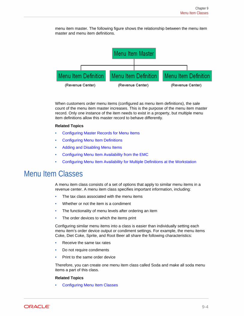
menu item master. The following figure shows the relationship between the menu itemmaster and menu item definitions.
When customers order menu items (configured as menu item definitions), the salecount of the menu item master increases. This is the purpose of the menu item masterrecord. Only one instance of the item needs to exist in a property, but multiple menuitem definitions allow this master record to behave differently.
Related Topics
• Configuring Master Records for Menu Items
• Configuring Menu Item Definitions
• Adding and Disabling Menu Items
• Configuring Menu Item Availability from the EMC
• Configuring Menu Item Availability for Multiple Definitions at the Workstation
Menu Item ClassesA menu item class consists of a set of options that apply to similar menu items in arevenue center. A menu item class specifies important information, including:
• The tax class associated with the menu items
• Whether or not the item is a condiment
• The functionality of menu levels after ordering an item
• The order devices to which the items print
Configuring similar menu items into a class is easier than individually setting eachmenu item’s order device output or condiment settings. For example, the menu itemsCoke, Diet Coke, Sprite, and Root Beer all share the following characteristics:
• Receive the same tax rates
• Do not require condiments
• Print to the same order device
Therefore, you can create one menu item class called Soda and make all soda menuitems a part of this class.
Related Topics
• Configuring Menu Item Classes
Chapter 9Menu Item Classes
9-4
Menu Item PricingA menu item price is the amount charged for the sale of a menu item. In Simphony,menu item prices are configured per menu item definition. Typically a menu itemdefinition is set with one price. You can set a definition with multiple prices (forexample, separate prices for a small, medium, and large soda), or no price (commonfor condiments).
When multiple prices are active for a menu item definition, the workstation searchesthe prices assigned to the definition starting with price sequence number 1, then pricesequence number 2, and so on. The workstation adds the first price that meets theactive level to the check. For example, based on the configuration described in thefollowing table, the item price is $8.00 when ordered on menu level 7, and $4.00 whenordered at any other level. The workstation’s logic is:
• The current level of the transaction is level 5.
• Price number 1 for the item is active on level 7. Continue to the next price.
• Price number 2 for the item is active on level 0. This represents any level. Theitem is $4.00.
Table 9-1 Correct Menu Prices and Levels
Price Sequence Number Price Level
1 8.00 7 - Double
2 4.00 0 - All Levels
When configuring multiple prices, you must always configure the 0 - All Levels pricelevel as the last price sequence number for the definition. For example, in the followingtable, the configurations in the previous table are reversed.
Table 9-2 Incorrect Menu Prices and Levels
Price Sequence Number Price Level
1 4.00 0 - All Levels
2 8.00 7 - Double
The workstation’s logic is:
• The current level of the transaction is level 7.
• Price number 1 for the item is active on level 0; this includes all levels. The itemis $4.00.
The item price $8.00 never becomes active because the 0 - All Levels price level is setas the first price sequence for the definition.
Related Topics
• Configuring Menu Item Prices
Chapter 9Menu Item Pricing
9-5
Screen Look Up (SLU)Similar to a number look up (NLU), a screen look up (SLU) is a touchscreen buttonthat gives workstation operators access to a list of items, except the workstation showseach item in the list as a separate touchscreen button. For example, the Open CheckSLU shows separate touchscreen buttons for each open check within the revenuecenter. When a workstation operator presses a SLU (for example, appetizers), theworkstation shows all menu items belonging to that SLU group. Typically menu itembuttons are not added directly to a touchscreen, but instead menu items are usuallylinked to SLU groups.
You can configure screen look ups for the following items:
• Menu Items
• Discounts
• Service Charges
• Tender/Media Records
• Family Groups
• Major Groups
• Custom Reports
• Open Checks
Related Topics
• Configuring Screen Look Ups for Menu Items
• Configuring Screen Look Ups for Discounts
• Configuring Screen Look Ups for Service Charges
• Configuring Screen Look Ups for Tender/Media Records
• Configuring Screen Look Ups for Family Groups
• Configuring Screen Look Ups for Major Groups
• Configuring Screen Look Ups for Custom Reports
• Configuring Screen Look Ups for Open Checks
Number Look Up (NLU)A number look up (NLU) is a touchscreen button that allows workstation operators toaccess a numbered list of items. The workstation operator can select one of thefollowing items in the list or enter the relevant NLU number to apply the item to thetransaction:
• Discounts
• Main Levels
• Service Charges
• Sub Levels
• Tender/Media
Chapter 9Screen Look Up (SLU)
9-6
If you want items to appear in NLU, you must configure a valid NLU number greaterthan zero (0) for each record. In an improperly configured database, it is possible fortwo records to have the same NLU number. If this occurs, the workstation applies thelowest numbered record (by object number) to the check. When showing discounts,service charges, and tender/media records, the workstation takes the active menulevel of the transaction into consideration.
Related Topics
• Configuring Number Look Ups for Discounts
• Configuring Number Look Ups for Service Charges
• Configuring Number Look Ups for Tender/Media Records
• Configuring Number Look Ups for Main and Sub Levels
Menu LevelsMenu levels determine where and when a workstation operator exists during atransaction. Simphony uses menu levels to:
• Determine what workstation operators can and cannot access during atransaction. For example, shared revenue centers are often configured so that tworevenue centers are active on different transaction levels, making some itemsvisible to one revenue center, while the other revenue center shows differentitems.
• Allow different prices for one menu item.
A main menu level and a sub menu level are always active. You can determine whichlevels are active by default (using the menu level hierarchy) and allow workstationoperators to change the levels during a transaction using a function key or menu levelpop-ups. You can also configure the status bar in the lower area of the workstation toshow main and sub level names that are active.
Auto Menu Level
You can set the main menu level, sub menu level, or both to change automatically at aspecific time of day. This configuration is called auto menu level, and controls pricingat different times of a day or week. For example, a revenue center can offer an EarlyBird Special (entrées are 20% off) every weekday from 3:00 p.m. to 6:00 p.m. For theEarly Bird Special to automatically occur, you can set an auto menu level from 3:00p.m. to 6:00 p.m. Monday through Friday. Set menu item definitions with multipleprices accordingly (one price for the Early Bird level and another general price).
You can set auto menu levels to overlap (although this is uncommon). In this case,menu levels become active based on the order in which you set the auto menu levels.After the workstation determines that one level is active, it does not look at the otherauto menu levels. Therefore, you must pay special attention when configuring multipleauto menu levels that occur on the same days at the same times.
As an example, based on the configuration described in the following table, at 3:00p.m., the main level becomes 2 - Early Bird. The main level does not change to 3 -Free Drinks at 4:00 p.m. When a transaction begins, the workstation considers theauto menu level table in the order of the configured auto levels. The workstationchecks the status of auto menu level and because it is active, the workstationcontinues to use the Early Bird menu level. In this example, the Free Drinks menulevel never becomes active.
Chapter 9Menu Levels
9-7
Table 9-3 Example of Incorrect Auto Menu Levels
Number
Main Level Start End Days Active
1 2 - Early Bird 15:00 18:00 Monday–Friday
2 3 - Free Drinks 16:00 17:00 Monday–Friday
According to the configuration in the following table, at 3:00 p.m. the main levelbecome 2 - Early Bird, and at 4:00 p.m. the main level becomes 3 - Free Drinks. Thisoccurs because the Free Drinks level is set at auto level 1, and starts after Early Bird,which is set at auto level 2.
Table 9-4 Example of Correct Auto Menu Levels
Number
Main Level Start Time End Time Days Active
1 3 - Free Drinks 16:00 17:00 Monday–Friday
2 2 - Early Bird 15:00 18:00 Monday–Friday
The workstation’s logic for these two menu levels is explained in the following table.
Table 9-5 Workstation Logic
Time Logic
15:00 Is auto level 1 active? No
Is auto level 2 active? Yes. Active main level is 2 - Early Bird
16:00 Is auto level 1 active? Yes. Active level is 3 - Free Drinks
17:00 Is auto level 1 active? No
Is auto level 2 active? Yes. Active main level is 2 - Early Bird
18:00 Is auto level 1 active? No
Is auto level 2 active? No
The main level is 1 - Regular, which is the default menu levelfor the revenue center
Menu Level Hierarchy
The following menu level hierarchy determines which setting controls the defaulttransaction menu levels:
Table 9-6 Menu Level Hierarchy
Number
Enterprise Management Console (EMC)Configuration
Description
1 Serving Periods If the active serving period has a main orsub level that is not 0, that is the activemain or sub level.
Chapter 9Menu Levels
9-8
Table 9-6 (Cont.) Menu Level Hierarchy
Number
Enterprise Management Console (EMC)Configuration
Description
2 Auto Menu Levels table If the time of day falls during an active automenu level, the main or sub level that isspecified for that auto menu level is theactive level.
3 Transaction Menu Level Defaults If the main or sub level set in the RVCParameters module is not 0, that is theactive main or sub level.
4 Main 1 and sub 1 are always defaults If the other hierarchy rules have not beenmet, the workstation defaults to main level1 and sub level 1.
Menu Level Configuration Tasks
Setting up menu levels consists of completing the following tasks:
• Set up main, sub, and custom menu levels
• Configure the default main and sub levels for serving periods
• Configure auto menu levels
• Configure the default menu levels for a revenue center
• Configure the active menu levels for menu item definitions
• Configure the functionality of menu items at the workstation
Related Topics
• Setting Main, Sub, and Custom Menu Levels
• Setting the Default Main and Sub Levels for Serving Periods
• Configuring Auto Menu Levels
• Setting the Default Menu Levels for a Revenue Center
• Configuring Active Menu Levels for Menu Item Definitions
• Configuring Menu Item Functionality on the Workstation
Sales ItemizersWhen the workstation operator adds items to a check, Simphony maintains varioussubtotals, known as itemizers, in the background. An itemizer is a bucket where totalsaccumulate. Simphony uses sales itemizers to separate menu item sales intocategories such as food, beverage, and merchandise. You can configure up to 16sales itemizers.
Related Topics
• Configuring Sales Itemizers
Chapter 9Sales Itemizers
9-9
Configuring Major Groups1. In the EMC, select the Enterprise, property, or zone, click Configuration and
Major Groups.
2. Insert a new record and enter a name for the major group (for example, Food).
3. Enter a number other than 0 (zero) in the Report Group field.
For example, you can enter 1 for the Food major group and enter 2 for the Liquormajor group. When you enter 0 (zero), the menu item does not appear on theMenu Item Report.
4. Click Save.
Related Topics
• Major Groups
Configuring Family Groups1. In the EMC, select the Enterprise, property, or zone, click Configuration and
Family Groups.
2. Insert a new record and enter a name for the family group (for example,Appetizers).
3. Enter a number other than 0 (zero) in the Report Group field.
For example, you can enter 1 for all family groups associated with Food and enter2 for all family groups associated with Liquor. When you enter 0 (zero), the menuitem does not appear on the Menu Item Report.
4. Select the Parent Major Group to which the new family group belongs.
5. Click Save.
Related Topics
• Family Groups
Configuring Menu Item ClassesFor instructions on configuring menu item classes for condiments and fixed pricemeals, see Creating Menu Item Classes for Condiment Groups.
1. In the EMC, select the Enterprise, property, revenue center, or zone, clickConfiguration and Menu Item Classes.
2. Insert a new record and enter a name for the new menu item class.
3. Double-click the new menu item class.
4. On the General tab, configure the appropriate settings:
Chapter 9Configuring Major Groups
9-10
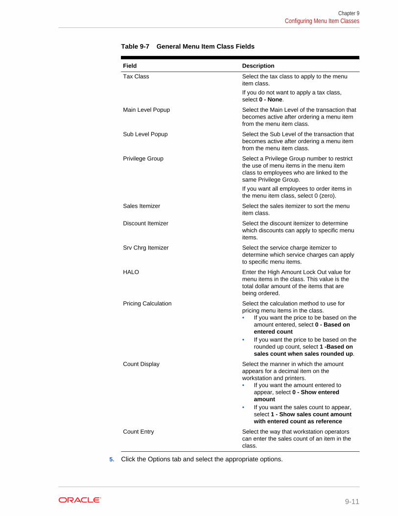
Table 9-7 General Menu Item Class Fields
Field Description
Tax Class Select the tax class to apply to the menuitem class.
If you do not want to apply a tax class,select 0 - None.
Main Level Popup Select the Main Level of the transaction thatbecomes active after ordering a menu itemfrom the menu item class.
Sub Level Popup Select the Sub Level of the transaction thatbecomes active after ordering a menu itemfrom the menu item class.
Privilege Group Select a Privilege Group number to restrictthe use of menu items in the menu itemclass to employees who are linked to thesame Privilege Group.
If you want all employees to order items inthe menu item class, select 0 (zero).
Sales Itemizer Select the sales itemizer to sort the menuitem class.
Discount Itemizer Select the discount itemizer to determinewhich discounts can apply to specific menuitems.
Srv Chrg Itemizer Select the service charge itemizer todetermine which service charges can applyto specific menu items.
HALO Enter the High Amount Lock Out value formenu items in the class. This value is thetotal dollar amount of the items that arebeing ordered.
Pricing Calculation Select the calculation method to use forpricing menu items in the class.• If you want the price to be based on the
amount entered, select 0 - Based onentered count
• If you want the price to be based on therounded up count, select 1 -Based onsales count when sales rounded up.
Count Display Select the manner in which the amountappears for a decimal item on theworkstation and printers.• If you want the amount entered to
appear, select 0 - Show enteredamount
• If you want the sales count to appear,select 1 - Show sales count amountwith entered count as reference
Count Entry Select the way that workstation operatorscan enter the sales count of an item in theclass.
5. Click the Options tab and select the appropriate options.
Chapter 9Configuring Menu Item Classes
9-11

Table 9-8 Menu Item Class Options
Option Description
1 - ON = Open-Priced Menu Items; OFF =Preset Menu Items
Select this option to require workstationoperators to enter a price when adding amenu item in the class. Deselect this optionif you are using preset prices.
3 - Negative Priced Menu Items Select this option if you want menu items inthis class to post a negative price.
4 - Increment Seat Number With Sale ofthese Menu Items
Select this option if you want to increase theseat number each time a workstationoperator adds a menu item in the class.
5 - Reference Entry Required Select this option to require workstationoperators to enter a reference entry whenadding menu items in the class.
6 - Validation Required Select this option if you want a validationchit to print at the validation printerdesignated in the Workstation module.
7 - Item Discounts May Be Applied to theseMenu Items
Select this option to allow menu items in theclass to be discounted with an item discount(manual discount only).
8 - Allow Menu Items in this Class to beNon-Priced
Select this option to allow menu items in theclass to be non-priced.
10 - ON = Use Sub Level Pricing; OFF =Use Main Level Pricing
Select this option to use Sub Level pricingfor the menu item class.
11 - Add to Guest Count Select this option to increase the guestcount each time a workstation operator addsmenu items in the class.
13 - Print Price on Order Chit Select this option if you want to print themenu item price on order printers. Thisoption is typically used with open-pricedmenu items.
14 - Do Not Put in Transaction Detail Select this option to prevent zero-priced ornon-priced menu items in the class fromprinting, appearing, or posting.
38 - Item is Shareable Select this option to allow menu items in theclass to be shared between two or moreseats, or two or more checks.
45 - Use KDS/Dining Course Number Select this option to use KDS/DiningCoursing with the menu item class.
6. Click Save.
Related Topics
• Menu Item Classes
Configuring Menu Item Prices1. In the EMC, select the Enterprise, property, revenue center, or zone, click
Configuration and Menu Item Maintenance.
2. Click Search to show all menu items, and double-click a menu item master record.
Chapter 9Configuring Menu Item Prices
9-12

3. Click Prices, and click the Insert button on the toolbar.
4. Select Price Sequence #1, enter the Default Price for the menu item, and clickOK.
5. Configure the price record. The following table explains the price record fields:
Table 9-9 Price Record Configuration Fields
Field Description
(Optional) Prep Cost Enter the menu item prep cost.
Tax Class Override If you want the menu item price to use adifferent tax class than the tax classconfigured for the menu item definition,select a new tax class from the list.
If you select 0-None, the price uses the taxclass configured for the menu item classassociated with the menu item definition.
Service Charge Group If the price includes a service charge, selecta service charge group from the list.
Active on Level Select the main or sub menu level in whichthis price becomes active.
If you select 0-All Levels, the price is activefor all menu levels.
Options If the price applies for the item whenordered as a course for a fixed price meal,select 1 - Price for Fixed Price MealCourse.
If the price applies when the item is orderedas a course for a fixed price meal as well aswhen ordered as a normal menu item entry,select 2 - Price for Fixed Price MealCourse and Regular Menu Item.
Effectivity Group If you want the price to become active at aspecific date and time, select thecorresponding effectivity group from the list.
6. Click Save.
7. Repeat Steps 3 through 6 to add more price definitions for the menu item.
Related Topics
• Menu Item Pricing
Setting Main, Sub, and Custom Menu Levels1. In the EMC, select the Enterprise, property, revenue center, or zone, click
Configuration and Menu Level Sets.
2. If you want to create a custom menu level, insert a new record and enter a customlevel set name.
3. If you want to define main menu levels, double-click Main.
4. If you want to define sub menu levels, double-click Sub.
Chapter 9Setting Main, Sub, and Custom Menu Levels
9-13
5. If you want to define menu levels for a custom level set, double-click the newcustom level that you created in Step 2.
6. Select the appropriate options:
a. If you want the menu level to change to the default level when a workstationoperator presses a touchscreen button corresponding to any menu level in thismenu level set again, select 1 - Pressing level key again reverts to defaultlevel.
b. If the menu level set is bound to a Default Master Group and you want theworkstation to switch the active parent menu item when the active menu levelchanges, select 2 - Bound to parent.
7. (Optional) Select the Default Master Group for the menu level set.
8. In the Menu Level Entries section, define the menu levels. For example, Breakfast,Lunch, Dinner.
9. (Optional) Define the Prefix or Suffix for each menu level to show on the checkdetail area and print on guest checks and customer receipts.
10. To define a menu level as the default level for the menu level set:
a. In the Options column, click the ellipsis point (...) symbol adjacent to thedefault menu level.
b. Select 1 - Default and click OK.
11. To define a menu level as an anonymous level for the menu level set:
a. In the Options column, click the ellipsis point (...) symbol adjacent to theanonymous menu level.
b. Select 2 - Anonymous and click OK.
The Default and Anonymous menu levels are generic, and are typically usedwith $0.00 priced menu item definitions that have names such as {SIZE} Hot Drinkor {TEMP} Drink.
12. Click Save.
Related Topics
• Menu Levels
Setting the Default Main and Sub Levels for Serving Periods1. In the EMC, select the revenue center, click Configuration and Serving Periods.
2. Double-click a serving period record.
3. In the General tab, select the Default Main Level and the Default Sub Level.
4. Click Save.
Related Topics
• Menu Levels
Configuring Auto Menu Levels1. In the EMC, select the Enterprise, property, revenue center, or zone, click
Configuration and Auto Menu Levels.
Chapter 9Setting the Default Main and Sub Levels for Serving Periods
9-14
2. In the Start column, enter the time at which the menu level becomes active.
3. In the End column, enter the time at which the menu level becomes inactive.
4. Select the Main Level and the Sub Level.
5. In the Options column, click the ellipsis point (...) symbol.
6. Select 1 - This Entry is Active, and select one or more of the following optionsthat correspond with the days that the menu level should become active:
• 2 - Active On Sunday
• 3- Active On Monday
• 4- Active On Tuesday
• 5- Active On Wednesday
• 6- Active On Thursday
• 7- Active On Friday
• 8- Active On Saturday
7. Click Save.
Related Topics
• Menu Levels
Setting the Default Menu Levels for a Revenue Center1. In the EMC, select the revenue center, click Setup and RVC Parameters.
2. In the General tab, select the Default Main Level and the Default Sub Level.
3. Click the Options tab and set the main and sub menu levels as follows:
• If you want the workstation to remain at the current main menu level aftercompleting a transaction, select 23 - Retain Current Main Level after aTransaction.
• If you want the workstation to remain at the current sub menu level aftercompleting a transaction, select 24 - Retain Current Sub Level after aTransaction.
4. Click Save.
Related Topics
• Menu Levels
Configuring Active Menu Levels for Menu Item Definitions1. In the EMC, select the Enterprise, property, revenue center, or zone, click
Configuration and Menu Item Maintenance.
2. Search for and then double-click a menu item master record.
3. If the menu item has multiple definitions, select a definition and click the Generaltab.
4. In the Menu Level Availability section, select the active main and sub levels for theitem.
Chapter 9Setting the Default Menu Levels for a Revenue Center
9-15
5. If you want the menu item definition to be active on all menu levels, click All.
6. If you want the definition to be active on a custom menu level:
a. Click Menu Levels Tab, select a Menu Level Set, and select the menu levels.
b. If you want the definition to be active on all custom levels, select Active on AllLevels.
7. If the menu item has multiple price records click Prices and select the ActiveMenu Level for each price definition.
If the menu item belongs to a class that uses sub level pricing (menu item classoption 10 - ON = Use Sub Level Pricing; OFF = Use Main Level Pricing is set),the application only lists sub levels. Otherwise, the application only lists the mainlevels.
8. Click Save.
Related Topics
• Menu Levels
Configuring Menu Item Functionality on the Workstation1. In the EMC, select the Enterprise, property, revenue center, or zone, click
Configuration and Menu Item Classes.
2. Double-click a menu item class.
3. If you want the main level of the transaction to change to another level when aworkstation operator orders a menu item from this class, select a new Main LevelPopup.
4. If you want the sub level of the transaction to change to another level when aworkstation operator orders a menu item from this class, select a new Sub LevelPopup.
5. If you want the transaction to return to the default main level after a workstationoperator orders a menu item from this class, select Main Level Default.
6. If you want the transaction to return to the default sub level after a workstationoperator orders a menu item from this class, select Sub Level Default.
7. Click the Options tab and select the appropriate options:
Table 9-10 Menu Item Functionality Options at the Workstation
Option Description
10 - ON = Use Sub Level Pricing; OFF =Use Main Level Pricing
Select this option if an item has multipleprice definitions and you want theworkstation to use sub level pricing for themenu item class.
26 - Keep Main Level With Repeat Rounds Select this option if you want the items in theclass to use the same main menu level thatwas in effect during the most recent serviceround when ordered using the RepeatRound touchscreen button.
Chapter 9Configuring Menu Item Functionality on the Workstation
9-16

Table 9-10 (Cont.) Menu Item Functionality Options at the Workstation
Option Description
27 - Keep Sub Level With Repeat Rounds Select this option if you want the items in theclass to use the same sub menu level thatwas in effect during the most recent serviceround when ordered using the RepeatRound touchscreen button.
28 - Print Main Level Prefix and Suffix Select this option if you want the workstationto show the main menu level prefixes orsuffixes on the check detail area and printon guest checks and customer receipts.
29 - Print Sub Level Prefix and Suffix Select this option if you want the workstationto show the sub menu level prefixes orsuffixes on the check detail area and printon guest checks and customer receipts.
69 - Prompt to lookup menu item definitionbased on current menu levels (RepeatRounds)
Select this option if you want the workstationto prompt workstation operators to run afresh menu item definition lookup based onthe current active menu levels when arepeatable menu item is unavailable.
You must also select options 26 - KeepMain Level With Repeat Rounds and 27 -Keep Sub Level With Repeat Rounds.
8. Click Save.
Related Topics
• Menu Levels
Configuring Sales Itemizers1. In the EMC, select the Enterprise level, click Descriptors and Sales Itemizers.
2. In the Text column, enter the names for each descriptor.
3. Click Save.
Related Topics
• Sales Itemizers
Configuring Master Records for Menu ItemsYou can add master records for menu items, along with menu item definitions andprices, using a template record. If there are no template records to use when creatinga property, you can add only a menu item master record, without adding definitionsand prices.
1. In the EMC, select the Enterprise, property, revenue center, or zone, clickConfiguration and Menu Item Maintenance.
2. Click Insert on the toolbar.
3. In the Select a task to perform drop-down list, select Add Master RecordWithout a Template, and enter the Name of the new menu item.
Chapter 9Configuring Sales Itemizers
9-17
4. Select a Major Group and a Family Group for the menu item.
5. Enter a Report Group number between 1 and 99 for the menu item. Menu ItemReports sort and list subtotals by Report Group. If the Report Group number is 0(zero), the menu item does not show on Menu Item Reports.
6. Select the appropriate value for the object number:
• If you want to insert the menu item in the next available position, select NextAvailable Position.
• If you want to define the record number or range for the new menu item recordor records, select Record Number Or Range, and enter the record numbersor ranges.
7. Click OK.
Related Topics
• Menu Item Master and Menu Item Definitions
Configuring Menu Item DefinitionsYou can add menu item definitions to existing menu item master records from bothtable and form view. This procedure explains how to add new definition records fromtable view.
1. In the EMC, select the Enterprise, property, revenue center, or zone, clickConfiguration and Menu Item Maintenance.
2. Click Insert.
3. In the Select a task to perform drop-down list, select Add Definition to Masters.
4. If you want to add definitions to a single menu item master record, select a menuitem mater record from the master record list.
5. If you want to add definitions to multiple menu item master records:
a. If the menu item master records to receive the definitions are not in sequentialorder, in the Range Type drop-down list, select Record Number or Rangeand enter individual record numbers or ranges (for example, 3, 5, 6-12).
b. If the menu item master records to receive the definitions are in sequentialorder, in the Range Type drop-down list, select Select Range and select thebegin and end items.
6. If you want to use an existing definition record as a template for creating the newdefinitions, select Use Template, and select the menu item definition record to useas a template.
7. If you are not using an existing definition record as a template for creating the newdefinitions, select the Menu Item Class for the new definitions.
8. Select the Definitions to Add.
9. If you are using a template menu item definition and you want the new definitionsto inherit price records from the template, in the Insert Price Records drop-downlist, select Inherit Price from Template.
10. If you want to insert new price records for the new menu item definitions, in theInsert Price Records drop-down list, select Specify Prices, select the number ofprices to create for the definitions, and enter the Price for the definitions.
Chapter 9Configuring Menu Item Definitions
9-18

Typically, you use this option when the new definitions have only one price recordeach.
11. Select Yes to confirm the insertion.
12. Click Save.
Related Topics
• Menu Item Master and Menu Item Definitions
Adding and Disabling Menu ItemsAdding a menu item is a different process than adding records in other EnterpriseManagement Console (EMC) modules. You can add master records, definitionrecords, and price records at the same time for the Enterprise in the Menu ItemMaintenance module. These instructions explain how to add menu item masterrecords with definition and price records. For information about adding masters,definitions, and prices individually, see the appropriate section:
• Configuring Master Records for Menu Items
• Configuring Menu Item Definitions
• Configuring Menu Item Prices
1. To add menu items in the EMC, select the Enterprise, property, revenue center, orzone, click Configuration and Menu Item Maintenance.
2. Insert a record.
3. If you opened Menu Item Maintenance from the revenue center, in the Select atask to perform drop-down list, select Add Master Record from Template.
4. Click Select adjacent to the Master to Copy field and select a template record.
5. Enter the Name of the new menu item.
6. Enter the Record Number of the item. By default, this field shows the nextavailable record number after the selected record to copy.
7. If you selected Add Master Record from Template, select Copy Menu ItemNames to copy all existing primary and foreign names, including Long Descriptors,from the original menu item to the new menu item.
8. If the menu item is priced the same for the entire Enterprise or property, selectUse the same price for all records, and enter the price in the text box next to theoption.
9. If the menu item has more than one definition and price, select Configure PricesIndividually, enter the price for the first definition in the Price column, and clickOK to add the menu item.
10. If you want to add another menu item, click Yes when prompted and repeat Steps4 through 9.
11. If you do not want to add another item, click No.
12. Click Save.
13. If you want to disable a menu item, select the Enterprise, property, revenue center,or zone, click Configuration and Menu Item Maintenance.
14. Double-click the menu item that you want to disable.
Chapter 9Adding and Disabling Menu Items
9-19

15. Click the General tab and deselect all main and sub levels in the Menu LevelAvailability section.
16. Click Save.
Related Topics
• Menu Item Master and Menu Item Definitions
Configuring Menu Item Availability from the EMCWhen a menu item has multiple definitions, changing the menu item availability fromthe Enterprise Management Console (EMC) affects all definitions.
1. In the EMC, select the property or revenue center, click Configuration and MenuItem Availability.
2. Change the Menu Item Status of the relevant item to 2 - Use AvailabilitySettings.
3. If you want to change the available count for a menu item, enter the count in theCount field.
4. If you want to make an item unavailable, select Out of Item.
5. Click Save.
Related Topics
• Menu Item Master and Menu Item Definitions
Configuring Menu Item Availability for Multiple Definitions atthe Workstation
By default, the Menu Item Availability function key only allows workstation operatorsto adjust the availability of the first menu item definition. To allow workstation operatorsto edit all definitions of an item from the workstation:
1. In the EMC, select the revenue center, click Setup and RVC Parameters.
2. On the Options tab, select 66 - Manage Menu Item Availability/Out of Item foreach Menu Item Definition.
3. Click Save.
Related Topics
• Menu Item Master and Menu Item Definitions
Configuring a Weighed Menu ItemA weighed menu item is measured in ounces, pounds, or kilograms and is priced perunit of measurement (for example, lobster is sold by the pound). You can measure theweight manually or automatically. The workstation calculates the price regardless ofthe weight entry method.
• Manual – The workstation operator can use the Item Weight function key andenter the weight of the item.
Chapter 9Configuring Menu Item Availability from the EMC
9-20

• Automatic – A scale attached to a workstation can automatically calculate theweight of the item.
There are two ways to configure a weighed menu item:
1. Assign the menu item to a menu item class that has option 15 - Weighed Itemsset.
2. Set a Tare Weight for menu item definition. See Understanding Tare Weight and Setting the Tare Weight for a Menu Item for more information.
Related Topics
• Understanding Tare Weight
Understanding Tare WeightTare weight is the weight of a container or wrapper that is deducted from the grossweight to obtain the net weight. Tare weight is used to accurately measure the weightof a weighed menu item. For example, in a restaurant with a salad bar where salad issold by weight, the customer should not be charged for the weight of the container. Toprevent this, a tare weight is configured for the salad menu item, and the weight of thesalad’s container is automatically subtracted from the weight of the salad.
When a weighed menu item posts to a guest check or customer receipt, the weightand tare weight (if set) appear and factor into the calculations with the same level ofprecision. The level of precision is determined by the Unit of Measure (UOM) asfollows:
• Kilograms: 0.000
• Pounds: 0.00
• Ounces: 0.0
This precision formatting meets the United States Department of Agriculture Weightsand Measures requirements for scale certification.
The UOM must match in the Enterprise Management Console (EMC) configurationand on the scale setting. For example, the scale must measure in ounces and EMCmust be set to use ounces. You cannot set the scale to measure in ounces and setEMC to measure in pounds. When a mismatch occurs between the scale and EMC,Ops rejects the posting and informs the workstation operator that there is a UOMmismatch due to configuration in EMC.
Related Topics
• Setting the Tare Weight for a Menu Item
• Configuring a Weighed Menu Item
• Configuring a Scale
Setting the Tare Weight for a Menu Item1. In the EMC, select the Enterprise, property, revenue center, or zone, click
Configuration and Menu Item Maintenance.
2. Click Search to show all menu items, and double-click a menu item master record.
Chapter 9Understanding Tare Weight
9-21

3. Click the Definition Records tab in the lower area of the screen.
4. In the Tare Weight field, enter the weight of the empty package for an item that issold by weight.
5. Click Save to apply the changes.
6. Select the Enterprise, property, revenue center, or zone, click Setup and ControlParameters.
7. Click the Options tab and select 13 - Convert Weight to System Unit ofMeasure. Setting this option allows Ops to convert the item weight to theproperty’s UOM if the UOM received from a scale does not correspond to theUOM established by the Property Parameters module in the EMC.
You must set this option in the United States to comply with the Department ofAgriculture Weights and Measure requirements.
8. Click Save.
Related Topics
• Understanding Tare Weight
Menu Item FeesYou can apply one or more menu item service charge fees (for example, a bottledeposit and a recycling fee) combined as a service charge group to a menu item.When the workstation operator adds a menu item (for example, Diet Coke) associatedwith a service charge group, the application adds the menu item fees under theservice charge group to the check. Auditors can track the revenue from specific menuitem fees, such as a recycling fee.
Related Topics
• Configuring Menu Item Fees
Configuring Menu Item Fees1. In the EMC, select the Enterprise, property, revenue center, or zone, click
Configuration and Service Charge Groups.
2. Insert a new service charge group or double-click the service charge group record.
3. Add or remove service charges to be included with this service charge group usingthe Add and Delete links.
4. Click Save.
5. Select the Enterprise, property, revenue center, or zone, click Configuration andMenu Item Classes.
6. Double-click the menu item class record.
7. On the General tab, select the Service Charge Group from the drop-down list toapply to the menu item class record.
8. Click Save.
9. Select the Enterprise level, click Configuration and Roles.
10. Select the role type, click the Operations tab and the Voids/Returns sub tab.
Chapter 9Menu Item Fees
9-22

11. Select Authorize/Perform Void of Fees.
12. Click Save.
13. Select the Enterprise, property, or revenue center, click Configuration and PageDesign.
14. Add the Display/Hide Menu Item Fees function key.
15. Click Save.
16. To show or hide menu item fees on the workstation, toggle the Display/HideMenu Item Fees function key.
Related Topics
• Menu Item Fees
Configuring Screen Look Ups for Menu Items1. In the EMC, select the Enterprise, property, revenue center, or zone, click
Descriptors and Menu Item.
2. Enter names for menu item screen look up groups (for example, breakfast, lunch,and dinner) in the Text column, and click Save.
3. Select the Enterprise, property, revenue center, or zone, click Configuration andMenu Item Maintenance.
4. Double-click a menu item and click General.
5. Select the relevant SLU group in the Touchscreen Properties section.
6. (Optional) Enter a SLU Sort Priority for the menu item.
7. Repeat Steps 4 and 5 for all menu items that you want to appear on screenlookups.
8. Select the Enterprise, property, revenue center, or zone, click Configuration andPage Design.
9. Double-click the transaction page on which you want the screen look up to appearon the workstation.
10. Click Other in the Page Design toolbar and click Sales SLU.
11. Select Menu Item as the Type, SLU as the Property, and the menu item screenlookup group as the Value.
12. Select the Menu Item Display Name and click Save.
13. If the revenue center uses hand held point-of-sale (POS) devices:
a. Select Dynamic SLU as the Property, and select a menu item screen look upgroup as the SLU Value.
b. Enter a non-zero value for the Visual State(s).
The application uses the Visual State value to link menu item screen look upswith their corresponding Visual State buttons, which workstation operators useto change the menu items that appear in the Dynamic SLU.
c. If you want to add more screen look ups to the Dynamic SLU, click Add.
d. Select the Menu Item Display Name and click Save.
Chapter 9Configuring Screen Look Ups for Menu Items
9-23

e. Insert buttons for each screen look up that you added to the Dynamic SLU.For example, if you added five screen look up groups to the Dynamic SLU,insert five buttons.
f. Select Function as the Type, and select Visual State from the function list.
g. Enter a Visual State value that you assigned to a screen look up group in Step13-b in the Arguments field.
h. Click Save.
Related Topics
• Screen Look Up (SLU)
Configuring Screen Look Ups for Discounts1. In the EMC, select the Enterprise, property, or zone, click Descriptors and
Discount.
2. Enter names for discount screen look up groups in the Text column, and clickSave.
3. Select the Enterprise property, or zone, click Configuration and Discounts.
4. Double-click a record and click NLU/SLU.
5. Select the relevant SLU group for the discount and click Save.
6. Repeat Steps 3 through 5 for all discounts that you want to appear in screenlookups.
7. Select the Enterprise, property, revenue center, or zone, click Configuration andPage Design.
8. Double-click the transaction page on which you want the screen look up to appearon the workstation.
9. Click Other in the Page Design toolbar and click Sales SLU.
10. Select Discount as the Type and the discount screen lookup group as the Value.
11. Click Save.
Related Topics
• Screen Look Up (SLU)
Configuring Screen Look Ups for Service Charges1. In the EMC, select the Enterprise property, or zone, click Descriptors and
Service Charge.
2. Enter names for service charge screen look up groups in the Text column, andclick Save.
3. Select the Enterprise property, or zone, click Configuration and ServiceCharges.
4. Double-click a record and click NLU/SLU.
5. Select the relevant SLU group for the service charge and click Save.
Chapter 9Configuring Screen Look Ups for Discounts
9-24

6. Repeat Steps 3 through 5 for all service charges that you want to appear in screenlookups.
7. Select the Enterprise, property, revenue center, or zone, click Configuration andPage Design.
8. Double-click the transaction page on which you want the screen look up to appearon the workstation.
9. Click Other in the Page Design toolbar and click Sales SLU.
10. Select Service Charge as the Type and the service charge screen lookup groupas the Value
11. Click Save.
Related Topics
• Screen Look Up (SLU)
Configuring Screen Look Ups for Tender/Media Records1. In the EMC, select the Enterprise property, or zone, click Descriptors and
Tender/Media.
2. Enter names for tender/media screen look up groups in the Text column, and clickSave.
3. Select the Enterprise or property, click Configuration and Tender/Media.
4. Double-click a record and click NLU/SLU.
5. Select the relevant SLU group for the tender/media and click Save.
6. Repeat Steps 3 through 5 for all tender/media records that you want to appear inscreen lookups.
7. Select the Enterprise, property, revenue center, or zone, click Configuration andPage Design.
8. Double-click the transaction page on which you want the screen look up to appearon the workstation.
9. Click Other in the Page Design toolbar and click Sales SLU.
10. Select Tender/Media as the Type and the tender/media screen lookup group asthe Value.
11. Click Save.
Related Topics
• Screen Look Up (SLU)
Configuring Screen Look Ups for Family Groups1. In the EMC, select the Enterprise, property, revenue center, or zone, click
Configuration and Page Design.
2. Double-click the transaction page on which you want the screen look up to appearon the workstation.
3. Click Other in the Page Design toolbar and click Sales SLU.
Chapter 9Configuring Screen Look Ups for Tender/Media Records
9-25

4. Select Menu Item as the Type, Family Group as the Property, and the familygroup to show in the screen look up as the Value.
5. Select the Menu Item Display Name and click Save.
Related Topics
• Screen Look Up (SLU)
Configuring Screen Look Ups for Major Groups1. In the EMC, select the Enterprise, property, revenue center, or zone, click
Configuration and Page Design.
2. Double-click the transaction page on which you want the screen look up to appearon the workstation.
3. Click Other in the Page Design toolbar and click Sales SLU.
4. Select Menu Item as the Type, Major Group as the Property, and the major groupto show in the screen look up as the Value.
5. Select the Menu Item Display Name and click Save.
Related Topics
• Screen Look Up (SLU)
Configuring Screen Look Ups for Custom Reports1. In the EMC, select the Enterprise, property, revenue center, or zone, click
Configuration and Page Design.
2. Double-click the transaction page on which you want the screen look up to appearon the workstation.
3. Click Other in the Page Design toolbar and click Sales SLU.
4. Select Custom Report as the Type and click Save.
Related Topics
• Screen Look Up (SLU)
Configuring Screen Look Ups for Open Checks1. In the EMC, select the Enterprise, property, revenue center, or zone, click
Configuration and Page Design.
2. Double-click the transaction page on which you want the screen look up to appearon the workstation.
3. Click Other in the Page Design toolbar and click Check SLU.
4. If you want the screen look up (SLU) to show open checks belonging to allemployees, select All Employees.
5. If you want the SLU to show open checks belonging to only the signed inemployee, select Currently Signed In Employee.
6. Select the type of open checks you want to appear on the SLU:
Chapter 9Configuring Screen Look Ups for Major Groups
9-26
Table 9-11 Open Check Options
Open Check SLU Option Description
All Checks Select this option if you want to show allopen checks.
Autofire Checks Only Select this option if you want to show onlyopen checks that are programmed to sendto order devices at a preset time.
All Except Autofire Checks Select this option if you do not want to showopen checks that are programmed to sendto order devices at a preset time.
Checks Held Items Only Select this option if you want to show onlyopen checks with items on hold.
All Except Checks with Held Items Select this option if you do not want to showchecks with items on hold.
All Except Autofire and Checks with HeldItems
Select this option if you do not want to showopen checks with items on hold and checksthat are programmed to send to orderdevices at a preset time.
Autofire Checks with Held Items Only Select this option if you want to show onlyopen checks that are programmed to sendto order devices at a predefined time andhave items on hold.
7. If you want to show only open checks that belong to particular order types (forexample, Dine-in or Take Out), select one or more Order Types, click Add, andclick Save.
Related Topics
• Screen Look Up (SLU)
Configuring Number Look Ups for Discounts1. In the EMC, select the Enterprise or property, click Configuration and Discounts.
2. Double-click a record and click NLU/SLU.
3. Enter a unique NLU number for the discount, and click Save.
You can enter a value between 1 and 255.
4. Repeat Steps 2 and 3 for all discounts that you want to appear in the number lookup.
5. Select the Enterprise, property, revenue center, or zone, click Configuration andPage Design.
6. Double-click the transaction page on which you want the number look up toappear on the workstation.
7. Insert a new button, select Function as the Type, select Discount NLU from thefunction list, and click OK.
8. Click Save.
Related Topics
• Number Look Up (NLU)
Chapter 9Configuring Number Look Ups for Discounts
9-27

Configuring Number Look Ups for Service Charges1. In the EMC, select the Enterprise or property, click Configuration and Service
Charges.
2. Double-click a record and click NLU/SLU.
3. Enter a unique NLU number for the service charge, and click Save.
You can enter a value between 1 and 255.
4. Repeat Steps 2 and 3 for all service charges that you want to appear in thenumber look up.
5. Select the Enterprise, property, revenue center, or zone, click Configuration andPage Design.
6. Double-click the transaction page on which you want the number look up toappear on the workstation.
7. Insert a new button, select Function as the Type, select Service Charge NLUfrom the function list, and click OK.
8. Click Save.
Related Topics
• Number Look Up (NLU)
Configuring Number Look Ups for Tender/Media Records1. In the EMC, select the Enterprise or property, click Configuration and Tender/
Media.
2. Double-click a record.
3. Enter a unique NLU number for the tender/media record, and click Save.
You can enter a value between 1 and 255.
4. Repeat Steps 2 and 3 for all tender/media records that you want to appear in thenumber look up.
5. Select the Enterprise, property, revenue center, or zone, click Configuration andPage Design.
6. Double-click the transaction page on which you want the number look up toappear on the workstation.
7. Insert a new button, select Function as the Type, select Tender/Media NLU fromthe function list, and click OK.
8. Click Save.
Related Topics
• Number Look Up (NLU)
Chapter 9Configuring Number Look Ups for Service Charges
9-28

Configuring Number Look Ups for Main and Sub Levels1. In the EMC, select the Enterprise, property, revenue center, or zone, click
Configuration and Page Design.
2. Double-click the transaction page on which you want the number look up toappear on the workstation.
3. Insert a new button, select Function as the Type, select either Main Level NLU orSub Level NLU from the function list, and click OK.
4. Click Save.
Related Topics
• Number Look Up (NLU)
Menu Item Waste ChecksMenu Item Waste describes menu items that are not sold to customers due to reasonssuch as spillage, spoilage and quality standards. There are three main characteristicsof a menu item waste check:
• A menu item waste check does not post to sales.
• Inventory is depleted when the application posts waste.
• A menu item waste check closes after posting. Service Total and Print functionsclose a waste check.
When menu item waste occurs, authorized workstation operators can begin a menuitem waste check and then enter wasted menu items. Wasted menu items appear inthe waste reports. Managers can generate Waste reports by revenue center, menuitem, employee, and waste reason. Depending on the reasons for waste, managerscan take action to reduce inventory loss. You can differentiate waste checks fromother checks in the Employee Journal Report and the Check Journal Report by theWaste Check banner on the check header.
The following table lists the functional differences between menu item waste checksand guest checks.
Table 9-12 Differences Between Waste Checks and Guest Checks
Function Menu Item Waste Checks Guest Checks
Kitchen Display Systems(KDS) or screen lookupsdisplay the check
No Yes
Reopen a closed check No Yes
Apply discounts No Yes
Apply taxes No Yes
Apply service charges No Yes
Apply guest count No Yes
Return item No Yes
Edit seat No Yes
Chapter 9Configuring Number Look Ups for Main and Sub Levels
9-29
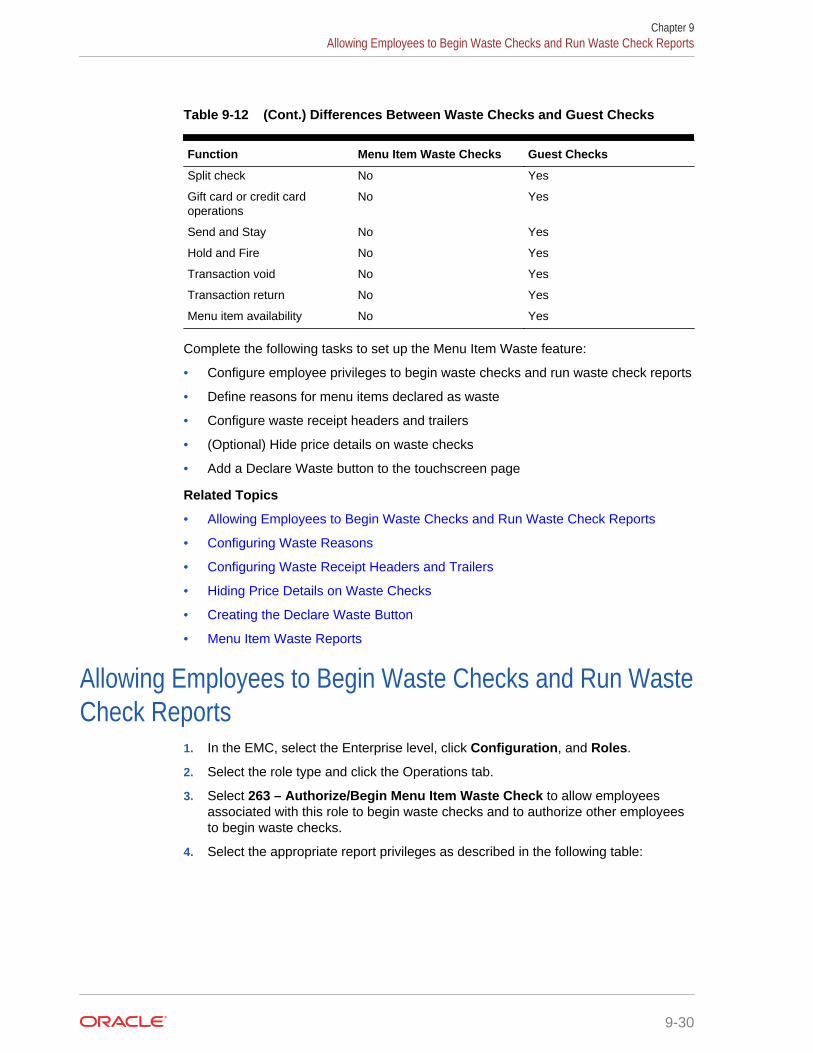
Table 9-12 (Cont.) Differences Between Waste Checks and Guest Checks
Function Menu Item Waste Checks Guest Checks
Split check No Yes
Gift card or credit cardoperations
No Yes
Send and Stay No Yes
Hold and Fire No Yes
Transaction void No Yes
Transaction return No Yes
Menu item availability No Yes
Complete the following tasks to set up the Menu Item Waste feature:
• Configure employee privileges to begin waste checks and run waste check reports
• Define reasons for menu items declared as waste
• Configure waste receipt headers and trailers
• (Optional) Hide price details on waste checks
• Add a Declare Waste button to the touchscreen page
Related Topics
• Allowing Employees to Begin Waste Checks and Run Waste Check Reports
• Configuring Waste Reasons
• Configuring Waste Receipt Headers and Trailers
• Hiding Price Details on Waste Checks
• Creating the Declare Waste Button
• Menu Item Waste Reports
Allowing Employees to Begin Waste Checks and Run WasteCheck Reports
1. In the EMC, select the Enterprise level, click Configuration, and Roles.
2. Select the role type and click the Operations tab.
3. Select 263 – Authorize/Begin Menu Item Waste Check to allow employeesassociated with this role to begin waste checks and to authorize other employeesto begin waste checks.
4. Select the appropriate report privileges as described in the following table:
Chapter 9Allowing Employees to Begin Waste Checks and Run Waste Check Reports
9-30
Table 9-13 Menu Item Waste Report Privileges
Privilege Name Allows the Employee to ...
31062 – Run Employee Waste Report Run the Employee Waste Report from theworkstation.
31063 – Run Menu Item Waste Report Run the Menu Item Waste Report from theworkstation.
31064 – Run Waste Summary Report Run the Waste Summary Report from theworkstation.
31065 – Run Waste Detail Report Run the Waste Detail Report from theworkstation.
5. Click Save.
Related Topics
• Menu Item Waste Checks
• Menu Item Waste Reports
Configuring Waste Reasons1. In the EMC, select the Enterprise level, click Descriptors and Void/Return/Waste
Reasons.
2. To add a new waste reason, enter a waste reason in an empty row under the Textcolumn and then select 2 - Use for Waste from the Options column.
3. To use an existing void or return reason also as a waste reason, select 2 - Use forWaste from the Options column adjacent to relevant the void or return reason. Theoptions work independently of each other; you can set one, both, or none.
4. Click Save.
Related Topics
• Menu Item Waste Checks
• Menu Item Waste Reports
Configuring Waste Receipt Headers and TrailersWhen you post a waste check, the guest check printer assigned to the workstationprints a waste receipt.
1. In the EMC, select the Enterprise level and click Descriptors.
2. Select one of the following options, depending on whether you want to configurereceipt headers or trailers:
• Waste Receipt Headers
• Waste Receipt Trailers
3. Perform one of the following actions:
• Enter text for the header or trailer in the rows under the Text column.
• Select a check box under the Use Logo column and then select a logo usingthe ellipsis icon in the Logo column.
Chapter 9Configuring Waste Reasons
9-31
4. Click Save.
Related Topics
• Menu Item Waste Checks
• Menu Item Waste Reports
Hiding Price Details on Waste ChecksA waste check measures the cost of wasted inventory as opposed to a guest checkthat posts the prices of menu items to the sales totals.
Complete these steps if you do not want to display prices of waste menu items in thecheck detail area of the workstation screen or print prices on waste receipts.
1. In the EMC, select the Enterprise level, click Setup, and Format Parameters.
2. Select the Options tab and select 54 - Do not display/print price for Waste.
3. Click Save.
Related Topics
• Menu Item Waste Checks
• Menu Item Waste Reports
Creating the Declare Waste ButtonTo declare waste, you need to add the Declare Waste function key to a page.
1. In the EMC, select the Enterprise, property, or revenue center, clickConfiguration and Page Design.
2. Open the Front of House page on which to place the Declare Waste button.
3. On the Edit tab, select the page area in which to define the Declare Waste button.
4. Click Button to add a button.
5. On the General sub-tab, enter the button name in the Legend field.
6. Select Function from the Type drop-down.
7. Click the black arrow directly beneath the Type drop-down and select DeclareWaste.
8. Highlight the Declare Waste button.
9. Position and size the button on the page. Use the Style arrow to change the color.
10. Click Save.
Related Topics
• Menu Item Waste Checks
• Menu Item Waste Reports
Chapter 9Hiding Price Details on Waste Checks
9-32
Menu Item Waste ReportsMenu Item Waste Reports provide an overview of discarded menu items resulting fromspillage, spoilage, or compromised quality standards so that you can take action toreduce inventory loss in your revenue center. You can generate waste reports byrevenue center, menu item, employee, and waste reason. The following Menu ItemWaste Reports are available:
• Waste Detail Report
• Waste Summary Report
• Employee Waste Report
• Menu Item Waste Report
The Waste Detail Report shows in-depth information about wasted menu itemsgrouped by the waste reason, as described in the following table. You can filter thereport data by waste reason.
Table 9-14 Waste Detail Report
Column Shows
Check # • The reason for discarding the menu items oringredients.
• The waste check number.• The total number of menu items or ingredients
discarded for the same waste reason.
Employee The name of the employee that created the wastecheck.
QTY Menu Item The quantity wasted followed by the name of the wastedmenu item or ingredient.
Amount The price of the wasted menu items or ingredients.
The Waste Summary Report shows an overview of the menu items wasted and thecorresponding waste quantity grouped by the waste reason, as described in thefollowing table. You can filter the report data by waste reason.
Table 9-15 Waste Summary Report
Column Shows
Waste Reason • The reason for discarding the menu items oringredients.
• The employee that recorded the waste (created thewaste check).
• The name of the wasted menu items or ingredients.
Quantity • The quantity of menu items or ingredients wasted.• The total number of menu items or ingredients
discarded for the same waste reason.
The Employee Waste Report shows a summary of the waste checks created by eachemployee, as described in the following table. When you filter the Employee Waste
Chapter 9Menu Item Waste Reports
9-33

Report for an employee, the report shows a summary of the waste checks created bythe selected employee.
Table 9-16 Employee Waste Report
Column Shows
Employee • The name of the employee that created the wastecheck.
• List of waste reasons added to the waste checksthat were created by the employee.
Quantity • The quantity of menu items or ingredients that werewasted for each waste reason.
• The total number of menu items or ingredientsdiscarded.
The Menu Item Waste Report shows the waste reason and the quantity of menu itemswasted grouped by menu item, as described in the following table. At the end of thereport, a summary of menu items wasted for each family group is shown. You can filterthe report by the family group.
Table 9-17 Menu Item Waste Report
Column Shows
Item Name • The name of the wasted menu item or ingredient.• The reason for discarding the menu item or
ingredient.
Quantity • The quantity corresponding to each menu item oringredient wasted.
• The total number of menu items or ingredientsdiscarded.
Family Group The family groups of each menu item wasted appear asa summary at the end of the report.
Quantity • The number of menu items or ingredients wastedfor each family group.
• The total number of menu items or ingredientsdiscarded.
Related Topics
• Menu Item Waste Checks
• Allowing Employees to Begin Waste Checks and Run Waste Check Reports
• Configuring Waste Reasons
• Configuring Waste Receipt Headers and Trailers
• Hiding Price Details on Waste Checks
• Creating the Declare Waste Button
Chapter 9Menu Item Waste Reports
9-34

10Condiments
A condiment is an item that is external to a regular menu item. For example, ketchup,salt, and chocolate sprinkles are all condiments. Condiments can also give furtherdetails to the cook preparing the menu item, such as a well-done steak or salad withranch dressing. In Simphony, condiments are often instructions or modifiers, such asthe words extra, add, substitute, and without.
Setting up condiments consists of completing the tasks listed in the following table:
Table 10-1 Condiment Configuration Tasks
Task More Information
Create condiment groups Configuring Condiment Groups
Create menu item classes for the condimentgroups
Creating Menu Item Classes for CondimentGroups
Create menu item master records forcondiments and assign to condiment classes
Creating Menu Item Master Records forCondiments
Create condiment sets and assigncondiments
Configuring Condiment Sets
Assign condiments to parent menu itemclasses
Assigning Condiments to Parent Menu ItemClasses
Assign default condiments to parent menuitems
Assigning Default Condiments to Parent MenuItems
Create condiment prefixes Configuring Condiment Prefixes
Configure additional settings for condimentappearance on workstations, guest checks,and customer receipts
Setting Condiment Appearance
• Condiment Groups and Condiment Sets
• Configuring Condiment Groups
• Creating Menu Item Classes for Condiment Groups
• Creating Menu Item Master Records for Condiments
• Configuring Condiment Sets
• Assigning Condiments to Parent Menu Item Classes
• Assigning Default Condiments to Parent Menu Items
• Condiment Prefixes
• Creating Condiment Prefix Menu Items
• Creating Menu Items Classes for Prefixes
• Activating Condiment Prefixes
• Deactivating Condiment Prefixes
10-1
• Configuring Touchscreen Buttons for Condiment Prefixes
• Setting Condiment Appearance
• Understanding the Popup Condiment Orderer
• Configuring a Popup Condiment Orderer Page
• Configuring a Revenue Center to Use the Popup Condiment Orderer
• Configuring a Menu Item Class to Use the Popup Condiment Orderer
Condiment Groups and Condiment SetsA condiment set defines the condiments that accompany the parent menu item. Forexample, a condiment set for a bacon cheeseburger includes the followingcondiments:
• Bacon
• Cheddar Cheese
• Mayonnaise
• Lettuce
• Ketchup
A condiment group defines the category to which a condiment set belongs anddictates its behavior.
Related Topics
• Configuring Condiment Groups
• Creating Menu Item Classes for Condiment Groups
• Creating Menu Item Master Records for Condiments
• Configuring Condiment Sets
• Assigning Condiments to Parent Menu Item Classes
• Assigning Default Condiments to Parent Menu Items
• Setting Condiment Appearance
Configuring Condiment Groups1. In the EMC, select the Enterprise, property, revenue center, or zone, click
Descriptors and Condiment Group Names.
2. Enter condiment group names (for example, Meat Group or Cheese Group) in theText field.
3. Click Save.
Related Topics
• Condiment Groups and Condiment Sets
Chapter 10Condiment Groups and Condiment Sets
10-2

Creating Menu Item Classes for Condiment Groups1. In the EMC, select the Enterprise, property, revenue center, or zone, click
Configuration and Menu Item Classes
2. Insert a new record, enter the class name, and double-click the new record.
3. On the General tab, select the Condiment Order Type from the drop-down list.
4. Click the Options tab and select 2 - ON = Condiment Menu Items; OFF =Regular Menu Items.
5. If you do not want to charge customers for the condiments in this class, select 8 -Allow Menu Items in this Class to be Non-Priced.
6. If you want each condiment in this class to print to a specific order device, select22 - ON = Use Own Output Link; OFF = Use Parent's (Condiments Only).
7. Click the Condiment Groups tab and select the Member Condiment Groups forthe class. For example, if the condiment class is Deli Meat Class, select MeatGroup from the Member Condiment Groups list.
8. Click Save.
9. Repeat Steps 2 through 8 to create menu item classes for all condiment groups.
Related Topics
• Condiment Groups and Condiment Sets
Creating Menu Item Master Records for Condiments1. In the EMC, select the Enterprise, property, revenue center, or zone, click
Configuration and Menu Item Maintenance.
2. Insert a new record and enter the condiment name (for example, Ham).
3. Search for and then double-click the new record
4. Insert a definition record and click the General sub-tab.
5. In the Name and Class section, select the Menu Item Class for the condiment.For example, if the condiment is Ham, select Deli Meat Class.
6. If this is a priced condiment:
a. Click the Prices sub-tab, insert a price definition, and enter the Price for thecondiment.
b. If you want the price to become active at a specific menu level, select ActiveOn Level and select the level.
7. Click Save.
8. Repeat Steps 2 through 6 to create menu item master records for all condiments.
Related Topics
• Condiment Groups and Condiment Sets
Chapter 10Creating Menu Item Classes for Condiment Groups
10-3
Configuring Condiment Sets1. In the EMC, select the Enterprise, property, revenue center, or zone, click
Configuration and Condiment Sets.
2. Insert a new record, enter a name for the condiment group, and then double-clickthe new record.
3. Click Add in the Condiments section.
4. In the Menu Item column, click the ellipsis point (...) symbol, select a condimentfrom the list, and click OK.
5. Enter the number of condiments that accompany the condiment group in theDefault Count field.
For example, if the condiment is a slice of cheddar cheese and you enter number2 as the default count, 2 slices of cheddar cheese accompany the condimentgroup.
6. In the Sort Order field, enter the order in which the workstation should show thecondiment on screen.
7. If you want the condiment to remain in the order when the workstation operatorchanges a menu item to plain (for example, when a workstation operator changesthe order to a plain bacon cheeseburger, the bacon and the cheese are notremoved), click the ellipsis point (...) symbol in the Options column, select 1 -Persist On Plain, and click OK.
8. Enter the Menu Item Definition Sequence number that coincides with thiscondiment. The Menu Item Definition Sequence number helps workstationoperators switch between condiments.
For example, the cheeseburger has two menu item definitions. If the customerorders definition 1, the cheeseburger should have cheddar cheese and if thecustomer orders definition 2, the cheeseburger should have mozzarella cheese.When configuring the condiment group for the cheeseburger, you must enter 1 asthe Menu Item Definition Sequence for the condiment cheddar cheese and 2 asthe Menu Item Definition Sequence for the condiment mozzarella cheese.
9. Repeat Steps 3 through 8 to add more condiments to the condiment group.
10. Click Save.
Related Topics
• Condiment Groups and Condiment Sets
Assigning Condiments to Parent Menu Item Classes1. In the EMC, select the Enterprise, property, revenue center, or zone, click
Configuration and Menu Item Classes.
2. Double-click a parent menu item class.
3. Click the Condiment Groups tab and select the appropriate Required CondimentGroups and Allowed Condiment Groups for the class. For example, if the parentmenu item class is Ham Sandwich Class, the required and allowed condimentgroups are listed in the following table:
Chapter 10Configuring Condiment Sets
10-4

Table 10-2 Examples of Required and Allowed Condiment Groups
Condiment Group Examples
Required Condiment Meat Group, Bread Group
Required condiments are sometimes referred to asforced condiments. Each Required Condiment Groupthat you select appears on the Forced Condiments tab.From there you can enter the Minimum and Maximumamounts for each item.
Allowed Condiment Meat Group, Bread Group, Cheese Group, SauceGroup, and Veggie Group
4. (Optional) Click the Forced Condiments tab.
5. For each required condiment group, enter the minimum and maximum condimentcount required to complete the order. For example, if you set the minimumcondiment count for Meat Group as 2, the workstation operator must add two meattypes to complete the order.
6. If you want to limit the number of selections that workstation operators can addfrom a condiment group at a certain menu level, enter the Threshold 1 and 2 foreach required condiment group. Typically, the menu level controls how much theapplication charges for a condiment. The threshold values allow you to determinewhen the price of a condiment changes, based on the number of items selected.
7. Click the Options tab and select the appropriate options as described in thefollowing table:
Table 10-3 Condiment Menu Item Class Options
Option Description
9 - Condiment Changes Print Group ofParent Menu Item
Select this option if you want the menuitems in this class to use the print group ofthe condiment.
21 - Require Number of Condiments toMatch Number of Parent Items
Select this option if you want the number ofthe required condiments belonging to themenu item class to match the number ofparent menu items ordered.
23 - Add Condiment Price to the ParentItem's Price on Check Only
Select this option if you want guest checksand receipts to show only a single price forthe parent menu item and its condiments(the price breakdown for each condimentdoes not appear).
30 - Sort Condiments by Print Group Select this option if you want condiments tosort according to their print group.
41 - Consolidate Menu Items withCondiments on Order Output
Select this option if you want order devicesto consolidate items with condiments andprint each condiment with the seat numberto which the condiment applies.
You must also select 6 - Print SeatNumbers with Individual Items in theOrder Devices module at the revenue centerlevel.
Chapter 10Assigning Condiments to Parent Menu Item Classes
10-5

Table 10-3 (Cont.) Condiment Menu Item Class Options
Option Description
42 - Consolidate Parents with MatchingCondiments on Order Output
Select this option if you want order devicesto consolidate parent menu items withidentical condiments.
8. Click Save.
9. Repeat Steps 2 through 7 for all parent menu item classes.
Related Topics
• Condiment Groups and Condiment Sets
Assigning Default Condiments to Parent Menu ItemsDefault condiments are not supported with Transaction Services. If you are usingTransaction Services, workstation operators need to add default condimentsseparately.
1. In the EMC, select the Enterprise, property, revenue center, or zone, clickConfiguration and Menu Item Maintenance.
2. Search for and double-click a parent menu item record.
3. Click the Default Condiments sub-tab and then click Add.
4. Click the ellipsis point (...) symbol in the Condiment Set column, select thecondiment set, and click OK.
5. (Optional) Enter the sort group number for the condiment set in the Sort Groupcolumn.
All condiment sets appear in the workstation according to the Sort Group.Condiment sets in Sort Group 0 appear first, followed by 1, 2, and so on. Itemsthat have the same Sort Group number appear as they are listed in the EMC.
6. Click the ellipsis point (...) symbol in the Options column and select 1 - Displaywhen in default state.
7. If you want to always charge customers for the condiment count, select 2 - Chargefor entire sales count and press OK.
For example, if a burger comes with 2 slices of cheese by default, the customer ischarged when there are 1 or 2 slices of cheese on the burger. If you do not selectthis option, customers are only charged when the condiment count exceeds thedefault count.
8. Click Save.
Related Topics
• Condiment Groups and Condiment Sets
Condiment PrefixesMany restaurants allow customers to modify menu items, such as adding, removing,increasing and decreasing the number of condiments on the item. You can insertprefixes (for example, No, Add, Extra) before the condiment on the guest check, order
Chapter 10Assigning Default Condiments to Parent Menu Items
10-6
devices, and customer receipts. This allows the workstation operator, server, kitchenstaff, and customer to see changes made to a default condiment. It also provideshelpful preparation instructions to the kitchen staff and helps to eliminate orderconfusion.
Complete the following tasks to set up condiment prefixes:
• Create condiment prefix menu items
• Create menu item classes for the prefixes
• Activate and deactivate condiment prefixes
• Configure separate touchscreen buttons for condiment prefixes
Related Topics
• Creating Condiment Prefix Menu Items
• Creating Menu Items Classes for Prefixes
• Activating Condiment Prefixes
• Deactivating Condiment Prefixes
• Configuring Touchscreen Buttons for Condiment Prefixes
Creating Condiment Prefix Menu Items1. In the EMC, select the Enterprise, click Configuration and Menu Item
Maintenance.
2. Insert a new record and name it Prefixes. This is a header menu item record andis used to distinguish the prefixes from other menu items.
3. Select the Prefixes header record and insert a new record. Enter the prefix (forexample, ADD) as the name for the new menu item record.
4. Double-click the record you created in Step 3, and click Menu Levels Tab.
5. Select Active on All Levels.
6. Click Prices and insert a $0 priced record.
7. Click Save.
8. Repeat Steps 3 through 7 to create records for the remaining four prefixes.
Related Topics
• Condiment Prefixes
Creating Menu Items Classes for Prefixes1. In the EMC, select the Enterprise, click Descriptors and Condiment Group
Names.
2. Enter a group name to show in the workstation for the condiment prefixes, andclick Save.
3. Select the Enterprise, click Configuration and Menu Item Classes.
4. Insert a new record and name it after a prefix (for example, ADD).
5. Double-click the new record.
Chapter 10Creating Condiment Prefix Menu Items
10-7
6. On the General tab, select the Condiment Prefix Type that corresponds to theprefix menu item class that you created in Step 4:
• 2 - No Prefix
• 3 - Add Prefix
• 4 - Sub Prefix
• 5 - Plain Prefix
• 6 - Reset Prefix
7. Click the Options tab, and select 2 - ON = Condiment Menu Items; OFF =Regular Menu Items and 8 - Allow Menu Items in this Class to be Non-Priced.
8. Click the Condiments Group tab and in the Member Condiment Groups section,select the condiment group that you created in Step 2.
9. Click Save.
10. Repeat Steps 4 through 9 to configure menu item classes for the remainingprefixes.
Related Topics
• Condiment Prefixes
Activating Condiment Prefixes1. In the EMC, select the Enterprise, property, revenue center, or zone, click
Configuration and Menu Item Classes.
2. For all regular menu item classes, select 65 - Support Enhanced Prefix Mode(Parent Only) and click OK.
If you are not using condiment prefixes, but you select option 65 - SupportEnhanced Prefix Mode (Parent Only), it is considered incorrect configuration andnegatively impacts the application.
3. Click Save.
Related Topics
• Condiment Prefixes
Deactivating Condiment PrefixesYou can deactivate condiment prefixes to prevent them from appearing in the Combo/Condiment Orderer.
1. In the EMC, select the Enterprise level, click Configuration and Menu ItemClasses.
2. Double-click a regular menu item class with condiments.
3. Click the Condiments Group tab and change all Allowed Condiment Groups toRequired Condiment Groups.
4. In the Allowed Condiment Groups section, select the condiment group you createdin the section Creating Menu Items Classes for Prefixes.
5. Click the Forced Condiments tab and set the Minimum value for the previouslyallowed condiment groups to 0 (zero).
Chapter 10Activating Condiment Prefixes
10-8
6. Repeat Steps 2 through 5 for all regular menu items with condiments.
7. Click Save.
Related Topics
• Condiment Prefixes
Configuring Touchscreen Buttons for Condiment Prefixes1. In the EMC, select the Enterprise, property, revenue center, or zone, click
Configuration and Page Design.
2. Locate the Combo/Condiment Orderer and deselect Allowed.
3. Click Save.
4. Insert a new button on the transaction screen, select Menu Item as the buttontype, and select a prefix as the menu item (for example, ADD).
5. Enter or generate a legend for the button, and click Save.
6. Repeat Steps 4 and 5 to configure touchscreen buttons for the remainingcondiment prefixes.
Related Topics
• Condiment Prefixes
Setting Condiment Appearance1. In the EMC, select the Enterprise, property, or revenue center, select Setup and
Format Parameters.
2. Click the Options tab and select the appropriate options:
• If you want to force as many condiments as possible to print together on eachline of guest checks and customer receipts, select 4 - Wrap Condiments onGuest Checks.
• If you want the workstation to hide previous round condiments and show onlythe parent menu item when a workstation operator picks up a check, select 35- Hide Previous Round Condiments on Display.
• If you want the check detail area to actively sort condiments while they areordered, select 45 - Sort Current Round Condiments on Screen. Condimentsorting occurs only when items are in different print groups and the parentallows condiment sorting.
3. Click Save.
4. Select the Enterprise, property, or revenue center, click Setup and ControlParameters.
5. Click the Options tab and select the appropriate options:
• If you want the workstation to show only condiments that customers areallowed to order with the parent menu item, select 37 - Enable CondimentMasking.
• If you want to allow workstation operators to add condiments out of order(conversational ordering), select 44 - Permit Required Condiments To BeEntered Out Of Order.
Chapter 10Configuring Touchscreen Buttons for Condiment Prefixes
10-9
6. Click Save to apply the changes.
7. Select the revenue center, click Setup and Order Devices.
8. Double-click a printer record and click the Options tab.
9. If you want condiments to print in red, select 10 - Print Condiments in Red(Overrides Print Class Settings).
10. Click Save.
Related Topics
• Condiment Groups and Condiment Sets
Understanding the Popup Condiment OrdererThe Popup Condiment Orderer provides a screen workflow that automaticallyadvances to all required condiment groups when ordering menu items.
The Popup Condiment Orderer resides in a template. The workstation operator usesthis template to create a page that pops up for required condiments. When adding amenu item (for example, Steak) that requires condiment selection to a transaction, thepage with the template appears as a popup where the workstation operator can selectthe required condiment groups (for example, meat temperature and sauce).
The workstation operator can also recall a Popup Condiment Orderer to modify therequired condiments of a previously ordered menu item. The workstation operator canselect the parent item or condiment in the check detail or select the Recall PopupCondiment Orderer function key (depending on configuration).
Unlike the regular Condiment Orderer, the Popup Condiment Orderer automaticallypops up and closes.
Complete the following tasks to set up the Popup Condiment Orderer:
• Configure a Popup Condiment Orderer page
• Configure a revenue center to use the Popup Condiment Orderer
• Configure a menu item class to use the Popup Condiment Orderer
Related Topics
• Configuring a Popup Condiment Orderer Page
• Configuring a Revenue Center to Use the Popup Condiment Orderer
• Configuring a Menu Item Class to Use the Popup Condiment Orderer
Configuring a Popup Condiment Orderer Page1. In the EMC, select the Enterprise, property, revenue center, or zone, click
Configuration and Page Design.
2. Insert a record for Popup Condiment Orderer if it does not exist.
3. Double-click the record to open it.
4. Select Specify Template and then select Popup Condiment Orderer from theInternal Templates list.
Chapter 10Understanding the Popup Condiment Orderer
10-10

This template is preset with a Condiment Orderer control and a Done button. Youcannot delete these elements from the template, nor can you copy elements to thistemplate. The Popup Condiment Orderer template supports two key functions:Void and Transaction Cancel.
5. In the Popup Type drop-down list, select where you want the Popup CondimentOrderer to appear on the page. (The Popup Types do not apply to Ops clientsrunning the Android and iOS mobile operating systems.)
• Full Screen
• Centered
• Next to Check Detail Area
• In Dynamic Content Area
6. Select Allow selection in check detail area if you want workstation operators toselect the current menu item and its condiments in the check detail area while thePopup Condiment Orderer is open.
7. Select Manually dismiss Condiment Orderer to have the Popup CondimentOrderer remain open after the workstation operator selects all requiredcondiments. The operator must use the Done function to close the PopupCondiment Orderer.
If you configure required condiment groups with a zero minimum count, selectManually dismiss Condiment Orderer. Otherwise the Popup Condiment Ordererautomatically closes because the application meets the minimum required count(zero) before the workstation operator orders a condiment in the group.
8. (Optional) Change the page settings, such as layout and button styles. You cannotmodify the dimmed settings.
9. (Optional) Repeat steps 2 through 8 for each Popup Condiment Orderer page youwant to create. Ops requires one page for initial condiment selection andsubsequent editing, although you can configure two pages.
When you designate Next Page/Panel for menu items (in menu item classes andon menu item buttons), Ops goes to the designated page or panel after the PopupCondiment Orderer closes (either manually or automatically).
10. Click Save.
Related Topics
• Understanding the Popup Condiment Orderer
Configuring a Revenue Center to Use the Popup CondimentOrderer
1. In the EMC, select the revenue center, click Setup and RVC Parameters.
2. In the Default Condiment Ordering Popup field, select the default automaticpopup to appear when the workstation operator orders a menu item with requiredcondiments for the revenue center:
• None
• Popup Condiment Orderer
Chapter 10Configuring a Revenue Center to Use the Popup Condiment Orderer
10-11
3. In the Default Condiment Editing Popup field, select the default automaticpopup to appear when the workstation operator selects a menu item with requiredcondiments in the check detail area for the revenue center:
• None
• Popup Condiment Orderer
4. Click Save.
Related Topics
• Understanding the Popup Condiment Orderer
Configuring a Menu Item Class to Use the PopupCondiment Orderer
The Popup Condiment Orderer configuration in the Menu Item Classes moduleoverrides the revenue center configuration in the RVC Parameters module.
If you do not configure a revenue center or menu item class to use the PopupCondiment Orderer, the feature is turned off. You can use a mix of the settings. Forexample, you can set the revenue center to use the Popup Condiment Orderer, andset specific menu items to use the revenue center parameter, other menu items to usea different Popup Condiment Orderer, and some menu items with no popup.
1. In the EMC, select the Enterprise, property, revenue center, or zone, clickConfiguration and Menu Item Classes.
2. Double-click the menu item class record.
3. In the Condiment Order Popup field, select the automatic popup to appear whenthe workstation operator orders a menu item with required condiments:
• No Popup
• Use Revenue Center Parameter
• Popup Condiment Orderer
4. In the Condiment Edit Popup field, select the automatic popup to appear whenthe workstation operator selects a menu item with required condiments in thecheck detail area:
• No Popup
• Use Revenue Center Parameter
• Popup Condiment Orderer
To use gestures on transaction pages, set the Condiment Edit Popup to NoPopup for the menu item classes, and use the Recall Popup CondimentOrderer function key to modify previously ordered required condiments.
5. Click Save.
Related Topics
• Understanding the Popup Condiment Orderer
Chapter 10Configuring a Menu Item Class to Use the Popup Condiment Orderer
10-12
11Combo and Fixed Price Meals
A combo meal consists of two or more menu items grouped together in combo mealgroups and sold to the customer for a single price. Quick service restaurants typicallysell combo meals to increase business by packaging the most frequently requestedmenu combinations (for example, hamburger, fries, and a drink) and offering them fora lower price than à la carte items.
A combo meal group allows you to configure the menu items within a group so thatOps knows which items to combine. Two typical combo meal groups are combo sidesand combo drinks. For example, you can configure a meal named Combo 1 with aprimary menu item called Combo Sandwiches and additional Combo Groups (such asCombo Drinks and Combo Side Items).
A fixed price meal (FPM) is a complete meal offered at a fixed price. For example,during special occasions or holidays, restaurants sometimes serve multi-course mealswith only a few menu item choices for each course, and charge a fixed total price.
There is no restriction on the number of FPMs or side items (courses). The workstationoperator can order multiple meals on the same seat. If the parent menu itemincrements the seat number, ordering multiple meals adds them to different seats (forexample, three pre-dinner specials). The sides can default to a placeholder menu itemthat the workstation operator replaces in a later round. Placeholder menu items can beshown or hidden in the check detail area.
You can configure FPMs like combo meals. Creating Combo Meal Groups containsinformation to assemble required items for a FPM, and assign alternate groups toallow guests to substitute items.
• Combo Meal Group Pricing
• Placeholder Menu Items in Combo Meals
• Creating Combo Meal Groups
• Creating Combo Meals
• Configuring Additional Combo Meal Settings
• Creating Combo Meal Pages
• Combo Meal Function Keys
Related Topics
• Creating Combo Meal Groups
• Creating Combo Meals
• Configuring Additional Combo Meal Settings
• Creating Combo Meal Pages
• Combo Meal Function Keys
11-1

Combo Meal Group PricingYou can use many pricing scenarios for combo meal groups, as described in thefollowing examples.
Pricing Combo Meal Groups Based on Side Items
You can price side items on the combo meal’s side items level instead of thetraditional pricing at the combo meal groups items level. In some instances, thissimplifies combo meal price configuration. If you set prices in both places, the pricingon the combo meal groups item level takes precedence. Consider the followingexamples:
• (Traditional Pricing) Combo Meal #1 Drinks cost $0.99
• (Traditional Pricing) Combo Meal #2 Drinks cost $1.09
• (Side Item Pricing) Milk (drink choice) costs $1.50 (upcharge)
1 Combo Meal #1: Root Beer $0.99
1 Combo Meal #1: Milk $1.50
1 Combo Meal #2: Root Beer $1.09
Pricing Combo Meal Groups Based on Size
The following figure illustrates the configuration of a basic combo meal group usingdifferent sizes and associated prices. A combo meal group called Combo Drinkscontains the menu items Small Coke, Medium Coke and Large Coke. The MediumCoke is the default drink for all applicable Order Types. The workstation operator doesnot need to make a selection when adding the combo meal item using the workstation.The application automatically adds the Medium Coke as the default selection. (Aworkstation operator can modify this choice using the sizing or substitute option.) Youcan use the prices of $1.00 for the Medium Coke and $2.00 for the Large Coke. Touse the combo size meal functionality, set the Small Coke as the Size 1 Item, theMedium Coke as the Size 2 Item and the Large Coke as the Size 3 Item. You must setSize 1-4 Item settings for all sizable combo group items listed. To allow workstationoperators to add or change combo meal item sizes, add Front of House buttons to thecombo transaction page using the Page Design module.
Chapter 11Combo Meal Group Pricing
11-2

Figure 11-1 Example of Pricing Based on Item Size
Pricing Combo Meal Groups Based on Menu Item Definition
The following figure shows another optional pricing convention. You can price anycombo meal menu item (for example, a Hamburger Combo to include all combo sideand drink items. Set the combo’s price in the menu item definition record (in the MenuItem Maintenance module), and deselect option 4 - Add Side Prices To Meal Price inthe Combo Meals module.
Figure 11-2 Example of Pricing Based on Menu Item Definition
Chapter 11Combo Meal Group Pricing
11-3
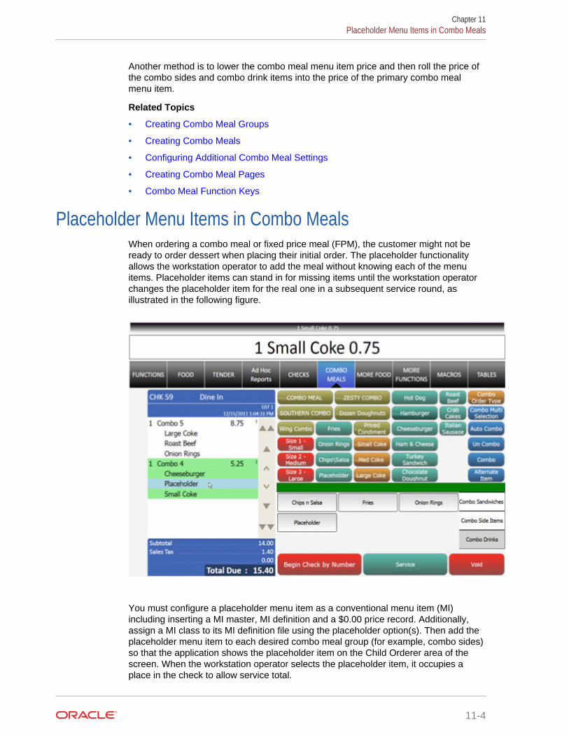
Another method is to lower the combo meal menu item price and then roll the price ofthe combo sides and combo drink items into the price of the primary combo mealmenu item.
Related Topics
• Creating Combo Meal Groups
• Creating Combo Meals
• Configuring Additional Combo Meal Settings
• Creating Combo Meal Pages
• Combo Meal Function Keys
Placeholder Menu Items in Combo MealsWhen ordering a combo meal or fixed price meal (FPM), the customer might not beready to order dessert when placing their initial order. The placeholder functionalityallows the workstation operator to add the meal without knowing each of the menuitems. Placeholder items can stand in for missing items until the workstation operatorchanges the placeholder item for the real one in a subsequent service round, asillustrated in the following figure.
You must configure a placeholder menu item as a conventional menu item (MI)including inserting a MI master, MI definition and a $0.00 price record. Additionally,assign a MI class to its MI definition file using the placeholder option(s). Then add theplaceholder menu item to each desired combo meal group (for example, combo sides)so that the application shows the placeholder item on the Child Orderer area of thescreen. When the workstation operator selects the placeholder item, it occupies aplace in the check to allow service total.
Chapter 11Placeholder Menu Items in Combo Meals
11-4

The workstation operator can replace the placeholder menu item at any time prior totendering or closing the check. After replacing it with a valid item (as shown in thefollowing figure), the workstation operator cannot change the item back to aplaceholder item. However, the workstation operator can substitute with another validitem.
Related Topics
• Creating Combo Meal Groups
• Creating Combo Meals
• Configuring Additional Combo Meal Settings
• Creating Combo Meal Pages
• Combo Meal Function Keys
Creating Combo Meal GroupsYou can configure combo meals using two Enterprise Management Console (EMC)modules: Combo Meal Groups and Combo Meals. Configure the Combo Meal Groupsmodule first and then configure the Combo Meals module.
1. In the EMC, select the Enterprise, property, revenue center, or zone, clickConfiguration and Combo Meal Groups.
2. Insert a record for a new combo meal group, or double-click an existing record.
3. Select the appropriate combo group configuration options:
Chapter 11Creating Combo Meal Groups
11-5

• 1 - Allow Discounts – Select this option if you want discounts to apply toitems in the group. The discount being applied must have option 25 -Discount Combo Meal Group Items set in the Discounts module.
• 2 - Substitution Group items use this sides price – Select this option if youwant to set the menu item price to the side’s combo meal price specified onthe combo meal form. The price setting occurs when a workstation operatorsubstitutes a combo meal side with a menu item from an alternate group.Deselect this option if you want to set the menu item price in the alternategroup.
4. (Optional) If you want to allow swappable side items, add Alternate Groups usingthe Add link.
• When alternate groups are present, workstation operators can substitutecombo side items with other combo meal groups. For example, the customermight want to have an onion rings side item that is generally available inCombo Meal #2 with a Combo Meal #4. You can add a Combo Onion Ringsalternate group that allows menu item substitution with a Combo Fries group.Configuring alternate side groups allows the application to substitute theseside menu items. You must configure an Alternate Side button (using the PageDesign module) to substitute items in Ops.
• If you are using Simphony version 2.7 MR3 or later, you configure fixed pricemeals (FPM) in the Alternate Groups field. Customers often want to substitutean appetizer or salad for the entrée portion of an FPM and this fieldaccommodates these substitutions.
5. Click the Items tab to configure all menu items within a combo meal group.
6. Click the Add and Delete links to add or remove menu items from the combo mealgroup.
7. Enter or select information in the following fields for each item:
Table 11-1 Combo Meal Group Fields
Field or Option Description
Primary Menu Item Select a menu item to use in the combomeal group. For instance, if the combogroup is called Combo Side Items, items inthis group could be Small Fries, MediumFries, Large Fries (if using the Size 1-4Items), and Onion Rings (among others).This field shows all menu item masterrecords that contain a definition in therevenue center.
Quantity Enter the number of times the menu item isneeded in the combo group. This field isavailable for instances when a value mealconsists of two burgers and a soda (as anexample).
1 - Default when no Order Type declared Select this option to make the selected itemthe default item for the combo group withoutan Order Type.
Chapter 11Creating Combo Meal Groups
11-6

Table 11-1 (Cont.) Combo Meal Group Fields
Field or Option Description
2-9 Default for Order Types 1-8 These options make the selected item thedefault item when Order Type 1 (through 8)is active. Deselecting these options forcesthe workstation operator to select an item tofulfill the combo meal requirements.
10 - Autofill If the operator orders one of the combomeals and more than one remaining item isrequired for the side, the quantity of the itemordered changes to the number of remainingitems to complete the side requirements.
Size 1-4 Items Select a menu item that will substitute forthe Primary Menu Item when using theCombo Size Size 1 through Size 4 functionkeys (set in Page Design under Type). Thislist shows all menu items assigned to thecombo group after saving the items to thedatabase. In the database, the Size 1-4fields of Combo Meal Group items are partof a self-referencing table. Because of this,EMC has two limitations: you cannot copy orpaste combo meal groups, and the Size 1-4Item fields populate only after you saveitems to the database. (For example, if youcreate a new combo group and add theitems Soda and Large Soda, you must savethese items before selecting either item inthis field.)
Size 1-4 Menu Levels Select a menu level that can affect the priceof the substituted Size 1-4 Items.
8. If you want to set specific side items with a different price (upcharge), click thePrices sub-tab. For example, perhaps Fries cost $0.00, but there is an extracharge of $1.25 when the customer orders Onion Rings.
9. Click the Add and Delete links to add or remove prices for each item. You canconfigure up to 8 prices for a single item.
Set the following fields when adding a price:
• Price – Enter the price to charge for the item.
• Prep Cost – Enter the à la carte price of the combo group item.
• Active On Level – Select the menu level on which the price is active.
• (Optional) Effectivity Group – Select the effectivity group for this price.
• (Optional) Date Start and Date End – Enter start and end dates.
10. Click Save.
Related Topics
• Combo and Fixed Price Meals
• Combo Meal Group Pricing
• Placeholder Menu Items in Combo Meals
Chapter 11Creating Combo Meal Groups
11-7

• Combo Meal Function Keys
Creating Combo Meals1. In the EMC, select the Enterprise, property, revenue center, or zone, click
Configuration, and Combo Meals.
2. Insert a record for a new combo meal, or double-click an existing record.
3. Select the menu item that represents the combo meal in the Menu Item Masterfield and click OK.
4. Enter the Priority for the combo meal when workstation operators press the AutoCombo function key.
5. In the Auto Combo Algorithm drop-down list, select the setting for the applicationto use when a workstation operator creates a combo meal from menu itemsalready listed on a check. When the workstation operator presses the AutoCombo function key, the application uses one of the following options to combinethe combo meal items:
• 0 - First Deal Found – Select this option to have the application use andcombine the first item(s) found.
• 1 - Best Deal for Customer – Select this option to combine the mostexpensive items as a combo meal.
• 2 - Best Deal for Merchant – Select this option to combine the leastexpensive items as a combo meal.
6. Select the appropriate options as described in the following table:
Table 11-2 Combo Meal Options
Option Description
1 - Disable Auto-Combo Recognition Select this option to prevent the combo mealfrom being considered when the workstationoperator presses the Auto Combo functionkey.
2 - Allow Auto-Combo in Previous Round Select this option to allow the combo mealto consider previous-round items when theworkstation operator presses the AutoCombo function key.
3 - Is Sized Combo Meal Select this option to allow the combo mealto use Combo Size Size 1-4 function keys,changing the size of the items ordered.
4 - Add Side Prices To Meal Price Select this option to add the prices of themeal’s side items to the price of the meal onthe Kitchen Display System (KDS) displayand the printed guest check.
5 - Only Print Priced Sides On Guest Check Select this option to prevent the meal's sideitems from printing on the guest check whenthey have no price, or when their price rollsinto the price of the meal.
6 - No Charge For Condiments Select this option when added condiments(to the meal) are non-priced.
Chapter 11Creating Combo Meals
11-8
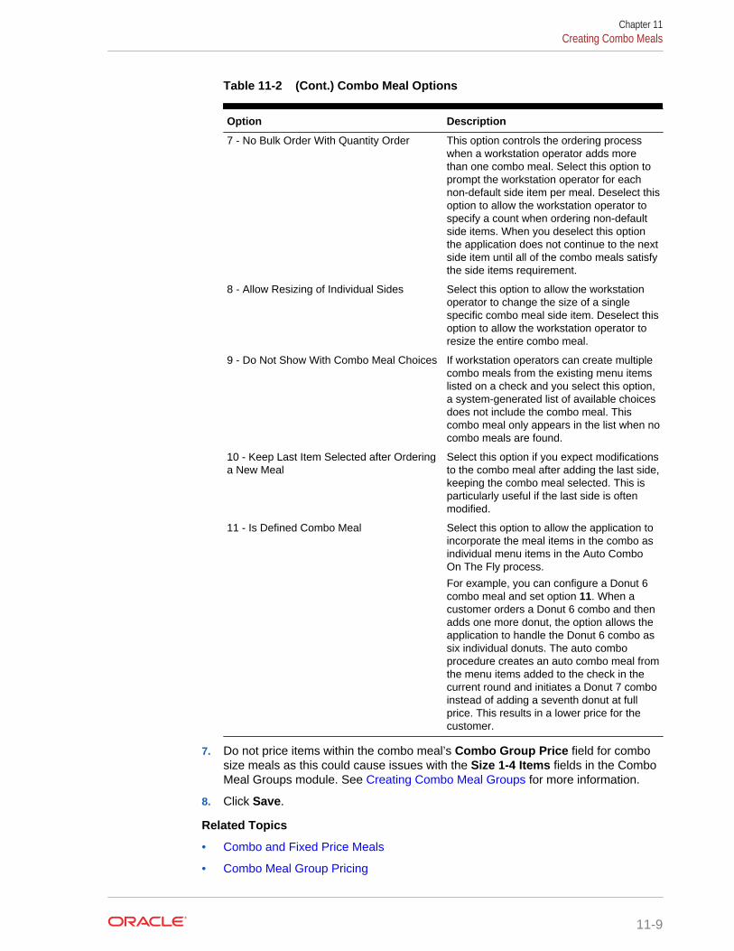
Table 11-2 (Cont.) Combo Meal Options
Option Description
7 - No Bulk Order With Quantity Order This option controls the ordering processwhen a workstation operator adds morethan one combo meal. Select this option toprompt the workstation operator for eachnon-default side item per meal. Deselect thisoption to allow the workstation operator tospecify a count when ordering non-defaultside items. When you deselect this optionthe application does not continue to the nextside item until all of the combo meals satisfythe side items requirement.
8 - Allow Resizing of Individual Sides Select this option to allow the workstationoperator to change the size of a singlespecific combo meal side item. Deselect thisoption to allow the workstation operator toresize the entire combo meal.
9 - Do Not Show With Combo Meal Choices If workstation operators can create multiplecombo meals from the existing menu itemslisted on a check and you select this option,a system-generated list of available choicesdoes not include the combo meal. Thiscombo meal only appears in the list when nocombo meals are found.
10 - Keep Last Item Selected after Orderinga New Meal
Select this option if you expect modificationsto the combo meal after adding the last side,keeping the combo meal selected. This isparticularly useful if the last side is oftenmodified.
11 - Is Defined Combo Meal Select this option to allow the application toincorporate the meal items in the combo asindividual menu items in the Auto ComboOn The Fly process.
For example, you can configure a Donut 6combo meal and set option 11. When acustomer orders a Donut 6 combo and thenadds one more donut, the option allows theapplication to handle the Donut 6 combo assix individual donuts. The auto comboprocedure creates an auto combo meal fromthe menu items added to the check in thecurrent round and initiates a Donut 7 comboinstead of adding a seventh donut at fullprice. This results in a lower price for thecustomer.
7. Do not price items within the combo meal’s Combo Group Price field for combosize meals as this could cause issues with the Size 1-4 Items fields in the ComboMeal Groups module. See Creating Combo Meal Groups for more information.
8. Click Save.
Related Topics
• Combo and Fixed Price Meals
• Combo Meal Group Pricing
Chapter 11Creating Combo Meals
11-9

• Placeholder Menu Items in Combo Meals
• Combo Meal Function Keys
Configuring Additional Combo Meal SettingsYou can configure additional combo meal options in various Enterprise ManagementConsole (EMC) modules.
1. To set tenders with incomplete combo meals:
a. Select the Enterprise, property, or zone, click Configuration and Tender/Media.
b. Double-click the tender media record.
c. Click the Options tab and the Printing Options sub-tab.
d. If you do not want the tender to be allowed when a meal is missing a sideitem, select 85 - Not Allowed With Incomplete Meals.
e. Click Save.
2. To set workstation operator privileges with incomplete combo meals andplaceholder items:
a. Select the Enterprise level, click Configuration and Roles.
b. Double-click the role record.
c. Click the Operations tab and the Transactions sub-tab.
d. Select 161 - Allow Incomplete Item to allow workstation operators to add aparent item without a required condiment. (The parent menu item must have59 - Allow Item Incomplete Based on Role set in the Menu Item Classesmodule.)
e. Select 164 - Authorize/Perform Service Total/Payment with Placeholderitem to allow workstation operators to perform or authorize tendering atransaction with a placeholder item. (You must also set option 85 - NotAllowed With Incomplete Meals in the Tender/Media module.)
f. Click Save.
3. To set revenue center operating parameters for combo meals:
a. Select the revenue center, click Setup and RVC Parameters.
b. Click the Options tab.
c. Select 51 - Allow Auto Combo Meal Recognition with the "Combo" key toallow the combo key to function with Auto Combo Meal recognition.
d. Select 52 - Allow Creation of Combo Meals from Previous Round MenuItems to allow the Auto Combo Meal recognition to create combo meals frommenu items that were ordered in previous rounds.
e. Select 55 - Show Combo Meal Choices to show a list of combo meal choiceswhen the workstation operator attempts to create meals from menu itemsalready on the check.
f. Select 58 - Auto Combo Items On The Fly to have the application createcombo meals from the menu items added to the check in the current round.
g. Click Save.
Chapter 11Configuring Additional Combo Meal Settings
11-10

4. To set menu item class options:
a. Select the Enterprise, property, revenue center, or zone, click Configurationand Menu Item Classes.
b. Double-click the menu item class record.
c. Click the Options tab.
d. Select 47 - Suppress Price with Combo Meal to make condiments free whenordered as part of a combo meal.
e. Select 59 - Allow Item Incomplete Based On Role to allow the workstationoperator to add a menu item without satisfying the required condiment’sconditions. (The role privilege 161 - Allow Incomplete Item must be set forthe workstation operator ordering a parent item with this menu item class.)
f. Select 60 - Placeholder if the menu item is a placeholder in a combo meal.
g. Select 61 - No Placeholder Display to hide placeholder items in the checkdetail area.
h. Click Save.
Related Topics
• Combo and Fixed Price Meals
• Combo Meal Group Pricing
• Placeholder Menu Items in Combo Meals
• Combo Meal Function Keys
Creating Combo Meal Pages1. In the EMC, select the Enterprise, property, revenue center, or zone, click
Configuration and Page Design.
2. Open the Front of House page (typically the Transaction page) on which to placethe combo meal keys and functions.
3. Click Button and create hardcoded combo meal menu item keys on theTransaction page.
Figure 11-3 Combo Meal Menu Item Key
Chapter 11Creating Combo Meal Pages
11-11

4. Click Other... and add a Condiment/Combo Orderer.
Add the Condiment/Combo Orderer to the same Transaction page as the combomenu items and function keys to view the combo meals and substitute side itemseasier.
5. Select the Condiment/Combo Orderer, select the Data tab, and then selectDisplay Title Bar. This area prompts workstation operators when required combomeal sides or condiments are not ordered.
6. Select Combo Meal Side to have the application generate and show any combomeal side items.
7. (Optional) Create combo meal size keys (if needed). These keys allow togglingbetween sizes of combo meal items. You can name the combo size keys for anactual size such as small, medium, or large, or Combo Size 1, Combo Size 2, andso on.
Figure 11-4 Combo Meal Size Key
8. Add the appropriate function keys to the Combo Meal Transaction page (forexample Combo, Un-Combo, Auto Combo and Combo Multi-Selection).
9. Configure keys for all individual menu items available (in particular combo groups).
10. Click Save.
Related Topics
• Combo and Fixed Price Meals
• Combo Meal Group Pricing
• Placeholder Menu Items in Combo Meals
• Combo Meal Function Keys
Combo Meal Function KeysWorkstation operators can use the following function keys with combo meals:
Chapter 11Combo Meal Function Keys
11-12

Table 11-3 Combo Meal Function Keys
Function Key Description
Auto Combo This key allows the workstation operator to create one ormore combo meals from existing menu items.
Combo When the workstation operator uses this key, the selecteditem or the last item on the check becomes a combo meal.The item must be a primary combo item. For example, ifthe combo meal is a burger with fries and a drink, theburger item must be the highlighted item or the last itemordered prior to pressing this key.
Combo Alternate Side This key allows the workstation operator to substitute acombo meal side with a selection from another combomeal group (for example, when a customer orders anappetizer instead of an entree in a combo meal).
Combo Bulk Order This key allows the workstation operator to order multiplecombo meals at a time. The workstation operator mustmeet each combo’s side item requirements before movingon to order the next combo’s side items.
Combo Multi Selection This key allows the workstation operator to select existingmenu items to combine into a combo meal. This functionshows the check details in a window, which allows theworkstation operator to select individual items to make upthe combo meal. This gives the workstation operatorgreater control in determining what is included in thecombo meal.
Un-Combo This key separates an existing combo meal into individualà la carte items (non-combo pricing takes effect).
Type - Combo Order Size Selecting this key changes the order size before orderingthe combo meal.
Type - Combo Size 1-4 These keys change the combo size after ordering thecombo meal. Using this key causes the workstation toresize the selected combo meal or combo meal side itemto selected sizes 1 through 4. If the workstation operatordoes not select an item, the last item on the check isresized.
Related Topics
• Combo and Fixed Price Meals
• Combo Meal Group Pricing
• Placeholder Menu Items in Combo Meals
• Creating Combo Meal Groups
• Creating Combo Meals
• Configuring Additional Combo Meal Settings
• Creating Combo Meal Pages
Chapter 11Combo Meal Function Keys
11-13

12Workstation Touchscreen Pages
Page templates allow you to customize a workstation touchscreen page in variousways. Page templates are categorized into the following types:
• Classic templates – These templates are similar to Simphony First Editiontouchscreen templates
• Blank templates – These templates are used for customized pages or a Log Inpage
• Tabbed templates – These templates are used for Sign In and Transaction pages
Tabbed templates allow the greatest functionality. With a tabbed template, you canconfigure multiple tabs on the page. Approximately 50 tabs and sub tabs can appearon a page, and each tab and sub tab contain up to 50 buttons. Having a large numberof buttons on a single page allows you to configure a small number of pages for arevenue center. A tab is used for navigation. Navigation on a page is consistent frompage to page (navigation bar and sub tabs).
Pages can contain buttons and more sophisticated content, such as dining tables,Screen Lookups (SLUs), numeric entry areas, and background panels for highlightedgroups of controls. All buttons performs a function.
The content appearing on a page can be dynamic based on the menu levels, servingperiod, employee class, or other criteria. For example, you can show a ManagerFunctions tab only if the manager is assigned to one of three manager employeeclasses.
When editing pages in the Enterprise Management Console (EMC) Page Designmodule, what-you-see-is-what-you-get.
• Configuring Function Keys
• Adding Menu Item Keys to the Transaction Page
• Adding a Service Total Key to the Transaction Page
• Adding Payment Keys to the Transaction Page
• Adding Discount and Service Charge Keys to the Transaction Page
• Configuring Macros
Configuring Function KeysFunction keys allow workstation operators to perform a variety of tasks, such asopening a cash drawer, authorizing a credit card, adding and transferring checks,printing customer receipts, and many other operations.
1. In the EMC, select the Enterprise, property, revenue center, or zone, clickConfiguration and Page Design.
2. Open the Front of House page on which to place a function key.
3. On the Edit tab, select the page area in which to define the function key.
12-1

4. Click Button.
5. On the General sub-tab, enter the key name in the Legend field.
6. In the Type drop-down, select Function.
7. Click the black arrow beneath the Type drop-down.
8. Select the function and click OK.
9. Position and size the button on the page. Use the Style arrow to change the color.
10. Click Save.
Adding Menu Item Keys to the Transaction Page1. In the EMC, select the Enterprise, property, revenue center, or zone, click
Configuration and Page Design.
2. Open the Front of House page (typically the Transaction page) on which to placethe menu item buttons.
3. On the Edit tab, select the page area in which to define the menu item buttons.
4. Click Button to add a button.
5. On the General sub-tab, enter the button name in the Legend field.
6. In the Type drop-down, select Menu Item.
7. Click the black arrow beneath the Type drop-down.
8. Select the menu item and click OK.
9. In the Menu Item Display Name drop-down, select the appearance for the menuitem name.
10. Position and size the button on the page. Use the Style arrow to change the color.
11. Click Save.
12. Repeat Steps 4 through 11 to create keys for each menu item.
Adding a Service Total Key to the Transaction Page1. In the EMC, select the Enterprise, property, revenue center, or zone, click
Configuration and Page Design.
2. Open the Front of House page (typically the Transaction page) on which to placethe service total button.
3. On the Edit tab, select the page area in which to define the service total button.
4. Click Button to add a button.
5. On the General sub-tab, enter the button name (Service Total) in the Legend field.
6. In the Type drop-down, select Tender/Media.
7. Click the black arrow beneath the Type drop-down.
8. Select the Service Total tender and click OK.
9. Position and size the button on the page. Use the Style arrow to change the color.
10. Click Save.
Chapter 12Adding Menu Item Keys to the Transaction Page
12-2

Adding Payment Keys to the Transaction PageYou can create payment keys for each type of payment tender (for example, Cash,Auth, Auth and Pay, Final Authorization, Split Tender).
1. In the EMC, select the Enterprise, property, revenue center, or zone, clickConfiguration and Page Design.
2. Open the Front of House page (typically the Transaction page) on which to placethe payment buttons.
3. On the Edit tab, select the page area in which to define the payment buttons.
4. Click Button to add a button.
5. On the General sub-tab, enter the button name in the Legend field.
6. In the Type drop-down, select Payment Tenders.
7. Click the black arrow beneath the Type drop-down.
8. Select the tender payment type and click OK.
9. In the Payment Configuration dialog, select the Payment Type and click OK.
10. Position and size the button on the page. Use the Style arrow to change the color.
11. Click Save.
Adding Discount and Service Charge Keys to theTransaction Page
1. In the EMC, select the Enterprise, property, revenue center, or zone, clickConfiguration and Page Design.
2. Open the Front of House page (typically the Transaction page) on which to placethe Discount and Service Charge buttons.
3. On the Edit tab, select the page area in which to define the Discount and ServiceCharge buttons.
4. Click Button to add a button.
5. On the General sub-tab, enter the button name in the Legend field.
6. On the General sub-tab, select the appropriate function from the Type drop-down.
• Discount
• Service Charge
7. Click the black arrow beneath the Type drop-down.
8. Select one of the following and click OK.
• Discount amount or percentage
• Service Charge amount or percentage
9. Position and size the button on the page. Use the Style arrow to change the color.
10. Click Save.
Chapter 12Adding Payment Keys to the Transaction Page
12-3
Configuring MacrosA macro is a button that, when pressed, executes a series of commands. Macros savetime when workstation operators frequently enter certain sequences or keystrokes.You can set macros to include menu items, service charges, discounts, tenders,function keys, alphanumeric keys, or a link to another macro.
Simphony allows a maximum of 255 macros in one revenue center. You can set eachmacro to include up to 16 steps (keys), and you can link up to 20 macros together.
1. In the EMC, select the Enterprise, property, revenue center, or zone, clickConfiguration and Page Design.
2. Open the Front of House page on which to place the macro button.
3. On the Edit tab, select the page area in which to define the macro button.
4. Click Button to add a button.
5. On the General sub-tab, enter the button name in the Legend field.
6. In the Type drop-down, select Function.
7. Click the black arrow directly beneath the Type drop-down, select the Macrofunction, and click OK.
8. Click the Edit Macro Keys button, and add the appropriate steps in the propersequence.
9. Highlight the macro button.
10. Position and size the button on the page. Use the Style arrow to change the color.
11. Click Save.
Chapter 12Configuring Macros
12-4
13Guest Checks
A guest check contains a record of all sales on the check, from the guest’s first orderto final payment.
• Configuring Guest Check Numbers
• Configuring Guest Check Headers and Trailers
• Creating a Tender to End the Current Service Round of Checks
• Understanding Fast Transactions
• Configuring Fast Transactions
• Understanding Full Seat Checks
• Configuring the Workstation to Print Full Seat Checks
• Creating a Full Seat Check Button
• Splitting Off an Item
• Configuring a Split Off Item Button
• Conversational Ordering
• Creating Menu Item Master Groups for Conversational Ordering
• Configuring Menu Level Sets for Conversational Ordering
• Configuring Menu Item Classes for Conversational Ordering
• Configuring Menu Items for Conversational Ordering
• Creating Front of House Buttons for Conversational Ordering
• Configuring Employee Privileges for Automatic Check Firing
• Configuring Automatic Check Firing
• Understanding Suspend and Resume
• Configuring Suspend and Resume
• Creating a Suspend and Resume Button
• Setting the Employee Auto Sign Out Period
• Understanding Follow Me
• Configuring Follow Me Checks
• Order Handling on Open Checks
• Holding and Sending Items to Order Devices
• Setting the Service Total to Send Items to be Prepared While the Check RemainsOpen
• Setting the Hold and Fire Option
• Setting the Hold and Fire Tender Notification
13-1
• Setting a Reminder for Items on Hold
• Setting Checks with Items on Hold to End Current Service Round
• Setting Check Handling with Held Items When Closing Checks
• Printing Multiple Languages on Guest Checks and Customer Receipts
• Configuring Right to Left Reading Languages
• Creating a Print Language List Button
• Creating Print Language Buttons
Configuring Guest Check NumbersThe guest check number can be between 1 and 9999 (a four-digit number). Generallycheck numbers start in numeric order. If a workstation operator begins check number1007, the next check number for the revenue center is 1008.
If you have multiple revenue centers and want to keep unique check numbers for eachrevenue center, you can assign an exclusive range or check numbers per revenuecenter. For example, Revenue Center 1 could have checks from 1000 to 1999 andRevenue Center 2 could have checks from 2000 to 2999.
1. In the EMC, select the revenue center, click Setup and RVC Parameters.
2. To set guest check numbers to generate automatically, enter the Min GuestCheck # and Max Guest Check # on the General tab.
When Simphony generates check numbers automatically, after reaching the MaxGuest Check # value, the next check number is the Min Guest Check # value.
3. To set workstation operators to manually assign guest check numbers, click theOptions tab and select 1 - Operator Assigns Check Numbers.
This option is typically used by properties that have guest checks with pre-printednumbers (rather than using roll printers).
4. Click Save.
Configuring Guest Check Headers and TrailersGuest check headers and trailers are leading and trailing lines that print on guestchecks. Typically, the header lines include the name of the property or revenue centerand address. The trailer lines generally show gratitude or promotional informationabout upcoming events. At hotels, guest check trailers are often configured to showroom charge information for the customer to complete. You can also set a header ortrailer line to print logos rather than text.
Headers print automatically on guest checks. You must set trailers to print per tender/media record.
1. In the EMC, select the Enterprise, property, revenue center, or zone, clickDescriptors and Guest Check Headers or Guest Check Trailers.
2. For each line, enter information in the following fields:
• Text – Enter the text to appear on the header or trailer.
• (Optional) Use Logo – Select this option if you want to print a logo rather thantext on the guest check header or trailer.
Chapter 13Configuring Guest Check Numbers
13-2
• (Optional) Logo – If you selected Use Logo, select an image.
3. Click Save.
4. To configure trailers to print for each tender media record, in the EMC, select theEnterprise, property or zone, click Configuration and Tender/Media.
5. Double-click the tender record.
6. Click the Options tab and the Printing Options sub tab.
7. Set the appropriate options as described in the following table:
Table 13-1 Trailer Printing Options for a Tender Record
Option Description
20 - Print Sales Itemizers Select this option to print the sales itemizerlines on guest checks, customer receipts,and memo checks when workstationoperators use the tender record. Deselectthis option to suppress printing of the salesitemizers.
21 - Print Summary Totals Select this option to print the summary totals(subtotal, tax, amount due, and change due)on guest checks, customer receipts, andmemo checks workstation operators pressthe key. Deselect this option to suppressprinting of the summary totals.
22 - Print Check Trailer Select this option to print the guest checktrailer lines at the end of the guest check.
28 - Print Guest Check Trailer on FastTransaction Customer Receipt
Select this option to print the guest checktrailer on the customer receipt whenworkstation operators use the tender toclose a fast transaction. Deselect this optionif you do not want the trailer to print oncustomer receipts.
8. Click Save.
Creating a Tender to End the Current Service Round ofChecks
You can configure the following two types of service total tenders that are commonlyused in restaurants to end the current service round of guest checks:
• Service total tenders that send menu items to order devices
• Service total tenders that send menu items to order devices and print the guestcheck
1. If you want to have the tender send menu items to order devices:
a. In the EMC, select the Enterprise or property, click Configuration andTender/Media.
b. Insert a new record, enter a name for the new tender record (for example,Send), and double-click the new tender record.
Chapter 13Creating a Tender to End the Current Service Round of Checks
13-3
c. In the Key Type field, select Service Total.
d. Click Menu Levels and select all main and sub menu levels.
e. Click Save.
2. If you want to have the tender send menu items to order devices and print theguest check:
a. Select the Enterprise or property, click Configuration and Tender/Media.
b. Insert a new record, enter a name for the new tender record (for example,Print), and double-click the new tender record.
c. In the Key Type field, select Service Total.
d. Click Options and Printing Options.
e. Select the following options:
• 13 - Print Memo Check
• 23 - Print Check on Demand
• 21 - Print Summary Totals
• 20 - Print Sales Itemizers
f. Click Menu Levels and select all main and sub menu levels.
g. Click Save.
Understanding Fast TransactionsA fast transaction does not require a workstation operator to use a Begin Check keyto start a new transaction. Workstation operators can quickly start transactions bepressing a menu item key or scanning an item. This functionality is often used in aretail/concession environment where a workstation operator stands in one place andquickly begins transactions repeatedly. It is also often used for bartenders who startmore transactions than a typical food server, and rarely assign customers to a specifictable or check number.
Related Topics
• Configuring Fast Transactions
Configuring Fast Transactions1. In the EMC, select the revenue center, click Setup and RVC Parameters.
2. Click the Options tab.
3. Select 15 - Allow Fast Transactions.
4. If you do not want customer receipts to automatically print after each fasttransaction, select 9 - On Demand Customer Receipts.
5. Click Save.
6. Select the Enterprise, property, revenue center, or zone, click Setup and FormatParameters.
7. Click the Options tab.
Chapter 13Understanding Fast Transactions
13-4
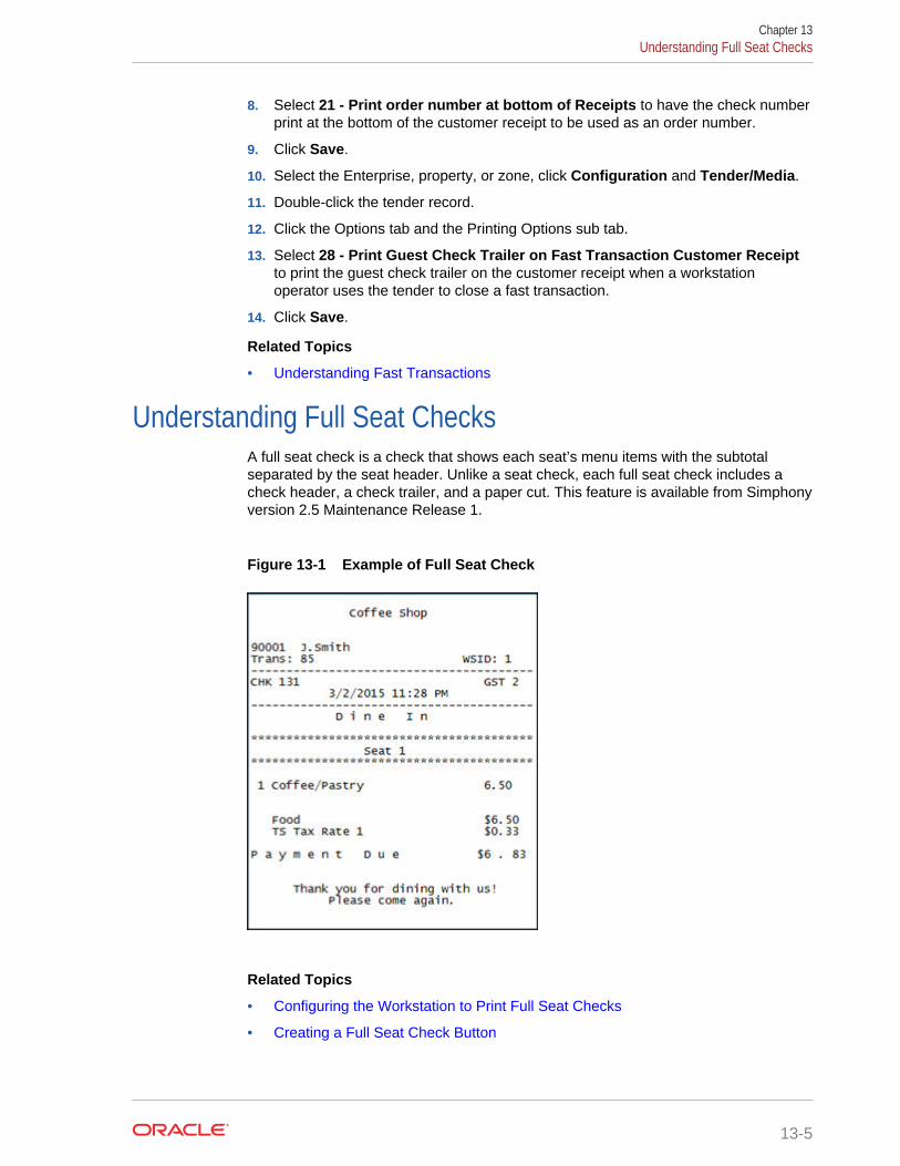
8. Select 21 - Print order number at bottom of Receipts to have the check numberprint at the bottom of the customer receipt to be used as an order number.
9. Click Save.
10. Select the Enterprise, property, or zone, click Configuration and Tender/Media.
11. Double-click the tender record.
12. Click the Options tab and the Printing Options sub tab.
13. Select 28 - Print Guest Check Trailer on Fast Transaction Customer Receiptto print the guest check trailer on the customer receipt when a workstationoperator uses the tender to close a fast transaction.
14. Click Save.
Related Topics
• Understanding Fast Transactions
Understanding Full Seat ChecksA full seat check is a check that shows each seat’s menu items with the subtotalseparated by the seat header. Unlike a seat check, each full seat check includes acheck header, a check trailer, and a paper cut. This feature is available from Simphonyversion 2.5 Maintenance Release 1.
Figure 13-1 Example of Full Seat Check
Related Topics
• Configuring the Workstation to Print Full Seat Checks
• Creating a Full Seat Check Button
Chapter 13Understanding Full Seat Checks
13-5
Configuring the Workstation to Print Full Seat Checks1. In the EMC, select the Enterprise or property, click Configuration and Tender/
Media.
2. Add a new record, and then toggle to Form View.
3. Select 2 - Service Total in the Key Type drop-down list.
4. Click the Options tab and Printing Options sub-tab.
5. Select 16 - Print Full Seat Check.
If you also select 14 - Print Seat Check, option 16 overrides option 14.
6. Select the following options:
• 21- Print Summary Totals
• 22 - Print Check Trailer
• 23 - Print Check on Demand
7. Click the Menu Levels tab, and then select all main and sub menu levels.
8. Click the Output tab, and then select the following options:
• Print on Customer Receipts
• Print on Guest Checks
• Print on Journal
9. Click Save.
10. Add a touchscreen button for the tender/media record that you created in step 2. Creating a Full Seat Check Button contains more information about configuring thetouchscreen button.
Related Topics
• Understanding Full Seat Checks
Creating a Full Seat Check Button1. In the EMC, select the Enterprise, property, revenue center, or zone, click
Configuration and Page Design.
2. Open the Front of House page on which to place the Full Seat Check button.
3. On the Edit tab, select the page area in which to define the Full Seat Checkbutton.
4. Click Button to add a button.
5. On the General sub-tab, enter the button name in the Legend field.
6. Select Tender/Media from the Type drop-down.
7. Click the black arrow directly beneath the Type drop-down and select Full SeatCheck.
8. Highlight the Full Seat Check button.
9. Position and size the button on the page. Use the Style arrow to change the color.
Chapter 13Configuring the Workstation to Print Full Seat Checks
13-6

10. Click Save.
Related Topics
• Understanding Full Seat Checks
Splitting Off an ItemA Split Off Item is a function key that enables workstation operators to separate (split)one or more items from a multiple quantity menu item entry so that it can be modifiedindependently from the original item.
For example, a customer orders 3 burgers with 2 pieces of cheese and bacon. Thecustomer then later requests to add ketchup to one burger. The workstation operatoruses Split Off Item to separate one of the burgers and adds ketchup to it.
Figure 13-2 Example of a Check Before and After Splitting an Item
When a workstation operator splits a multiple quantity menu item with condiments(required or non-required condiments) the following results appear on the check:
• The condiments of the original item and their quantities are carried over to eachsplit item.
• The quantity of the original parent menu item is reduced by the number of itemssplit.
For example, if the workstation operator originally adds 3 burgers, after splitting oneitem, the original item entry shows as 2 burgers while the new split entry shows as 1burger.
Chapter 13Splitting Off an Item
13-7

Related Topics
• Configuring a Split Off Item Button
Configuring a Split Off Item Button1. In the EMC, select the Enterprise, property, revenue center, or zone, click
Configuration and Page Design.
2. Open the Front of House page on which to place the Split Off Item button.
3. On the Edit tab, select the page area in which to define the Split Off Item button.
4. Click Button to add a button.
5. On the General sub-tab, enter the button name in the Legend field.
6. Select Function from the Type drop-down.
7. Click the black arrow directly beneath the Type drop-down and select Menu Item.
8. Highlight the Split Off Item button.
9. Position and size the button on the page. Use the Style arrow to change the color.
10. Click Save.
Related Topics
• Splitting Off an Item
Conversational OrderingConversational ordering allows workstation operators to add specially configuredmenu items for guests who order these items in no particular sequence. For example,in a coffee shop, the workstation operator requires the following items:
• Drink Type (Espresso, Latte, Mocha, Tea)
• Drink Size (Small, Medium, Large)
• Drink Temperature (Hot, Iced)
• Condiments or Modifiers (Whipped Cream, Cinnamon, Skim Milk)
When using conversational ordering, the workstation operator adds the order as aguest states items (for example, an iced mocha, medium size, with whipped cream),improving Speed of Service (SOS), ease of ordering for guests, and overall orderaccuracy.
Setting up conversational ordering consists of completing the tasks listed in thefollowing table:
• Creating Menu Item Master Groups
• Configuring Menu Level Sets
• Configuring Menu Item Classes
• Setting Menu Items
• Creating Front of House buttons
Chapter 13Configuring a Split Off Item Button
13-8
Related Topics
• Creating Menu Item Master Groups for Conversational Ordering
• Configuring Menu Level Sets for Conversational Ordering
• Configuring Menu Item Classes for Conversational Ordering
• Configuring Menu Items for Conversational Ordering
• Creating Front of House Buttons for Conversational Ordering
Creating Menu Item Master Groups for ConversationalOrdering
1. In the EMC, select the Enterprise, property, or zone, click Configuration andMenu Item Master Groups.
2. Insert a new Menu Item Master Group. In the coffee shop example, you couldcreate the following groups: Drinks, Espresso, Latte, Mocha, and Americano.
3. Click Save.
Related Topics
• Conversational Ordering
Configuring Menu Level Sets for Conversational Ordering1. In the EMC, select the Enterprise, property, revenue center, or zone, click
Configuration and Menu Level Sets.
2. Insert a new Menu Level Set. In the coffee shop example, you could create Sizeand Temperature Menu Level Sets.
3. Select the Default Master Group for each Menu Level Set.
In the coffee shop example, you could select Drinks as the Default Master Group.
4. Double-click a Menu Level Set to open it in form view.
5. In the General section, select 2 - Bound to parent to bind the Menu Item MasterGroup (for example, Drinks) to the custom Menu Levels (for example, Size andTemperature).
When a guest initially orders a drink by either Size or Temperature, those menuitems link to the Menu Item Master Group, which also link to Anonymous MenuLevel Entry Options. This allows the workstation operator to add items in the exactorder that the guest states or orders them.
6. In the Menu Level Entries section, click Add.
7. Enter menu level names for the Menu Level Set (for example, you could addSmall, Medium, and Large Menu Level Entries to the Size Menu Level Set).
8. For each Menu Level Entry, select the Default and Anonymous options.
Selecting these options allows the menu level sets to serve as temporary $0.00placeholders for menu items when guests order them out of sequence.
9. Click Save.
Chapter 13Creating Menu Item Master Groups for Conversational Ordering
13-9
Related Topics
• Conversational Ordering
Configuring Menu Item Classes for Conversational Ordering1. In the EMC, select the Enterprise, property, revenue center, or zone, click
Configuration and Menu Item Classes.
2. Insert a new Menu Item Class record.
• For each menu item that a guest can order through Conversational Ordering,create at least two Menu Item Classes to accommodate the guest in orderingthe same menu item in different ways. In the coffee shop example, eachcoffee type might have two classes: Latte Anonymous and Latte Defined.Create the Anonymous class first.
• Create a generic Menu Item Class to assign only to Menu Item Definitions thatare $0.00 priced menu items. In the coffee shop example, the Menu ItemClass Drink Anonymous can be used for Menu Item Definitions such as {SIZE}Large Drink or {TEMP} Hot Drink. This Menu Item Class is assigned to theDefault Master Group named Drinks.
3. Double-click a Menu Item Class to open it in form view.
4. On the General tab, in the Condiment Order Type drop-down list, select 2 -Replace in Condiment Group. Setting this option replaces the previouslyselected condiment with the latest condiment choice when the workstationoperator selects condiments. If you set the Increment option, a priced condimentcan be added to a transaction, such as a shot of espresso.
5. Click the Options tab.
6. For each Menu Item Class with Anonymous in the name, select the followingoptions:
• 8 - Allow Menu Items in this Class to be Non-Priced
• 49 - Participates in Menu Item Master Switching
• 50 - Anonymous Menu Item
7. For each Menu Item Class with Defined in the name, select the following options:
• 8 - Allow Menu Items in this Class to be Non-Priced
• 49 - Participates in Menu Item Master Switching
8. For the generic Menu Item Class (for example, Drink Anonymous), select thefollowing options:
• 8 - Allow Menu Items in this Class to be Non-Priced
• 49 - Participates in Menu Item Master Switching
• 50 - Anonymous Menu Item
9. Click the Condiment Groups tab.
10. For each Menu Item Class, select the appropriate condiment groups:
• Required Condiment Groups – These condiment groups must be enteredwhen a workstation operator adds menu items in this class.
Chapter 13Configuring Menu Item Classes for Conversational Ordering
13-10
• Allowed Condiment Groups – These condiment groups are allowed to beentered as condiments for menu items in this class.
• Member Condiment Groups – These condiment groups consist of menu itemsin this class.
11. Click Save.
Related Topics
• Conversational Ordering
Configuring Menu Items for Conversational Ordering1. In the EMC, select the Enterprise, property, revenue center, or zone, click
Configuration and Menu Item Maintenance.
2. Insert a menu item master record for each menu item (including condiments) thatcan be ordered using conversational ordering. You need to account for all potentialordering combinations a guest might use. Use braces {} to surround the genericvariables such as {SIZE} and {TEMP}.
In the coffee shop example shown in the following figure, you might have recordsfor {SIZE} {TEMP} Drink, {SIZE} Hot Drink, and so on.
Chapter 13Configuring Menu Items for Conversational Ordering
13-11

Figure 13-3 Menu Item Master Records for Conversationally Ordered Items
3. Select the Major Group, Family Group, and Master Group.
4. Click the Definition Records tab in the lower area of the page.
5. Set the following for each record:
• Menu Item Class
• Menu Item Price
• Menu Level Availability
• Default Condiments
6. Click Save.
Related Topics
• Conversational Ordering
Chapter 13Configuring Menu Items for Conversational Ordering
13-12
Creating Front of House Buttons for ConversationalOrdering
1. In the EMC, select the Enterprise, property, revenue center, or zone, clickConfiguration and Page Design.
2. Open the Front of House page on which to place menu item master buttons.
3. On the Edit tab, select the page area in which to define the menu items (includingcondiments) (typically the transaction area).
4. Click Button to add a button.
5. On the General sub-tab, select the appropriate function from the Type drop-down.
6. Click the black arrow beneath the Type drop-down.
7. Position and size the button on the page. Use the Style arrow to change the color.
8. In the Legend field, enter the button name.
9. Click Save.
10. Repeat these steps to create buttons for each of the menu item master names.
Related Topics
• Conversational Ordering
Configuring Employee Privileges for Automatic Check Firing1. In the EMC, select the Enterprise level, click Configuration and Roles.
2. Double-click an employee role, click the Operations tab and the Guest Checkssub-tab.
3. Select the appropriate privileges. The following table describes the privilegescorresponding to automatic check firing.
Table 13-2 Employee Guest Check Privileges for Automatic Check Firing
Privilege Description
183 - Begin Autofire Check using [BeginAutofire Check] Key
Select this option to allow employees in thisrole to create checks that automatically fireat a preset time using the Begin AutofireCheck function key.
184 - Authorize/Perform Pickup of AutofireCheck Belonging to Another Operator
Select this option to allow employees in thisrole to pick up and edit checks that fire at apreset time from other employees.
185 - Authorize/Perform Edit of AutofireDate/Time
Select this option to allow employees in thisrole to modify the date and time that checksare set to automatically fire.
4. If you want to allow employees in this role to generate the Autofire Open CheckReport from the workstation, click the Ad Hoc Reports sub-tab and select 31030 -Run Autofire Open Check Report.
5. Click Save.
Chapter 13Creating Front of House Buttons for Conversational Ordering
13-13

Configuring Automatic Check Firing1. In the EMC, select the revenue center, click Setup and RVC Parameters.
2. Click the Autofire tab and configure the settings as described in the following table:
Table 13-3 Automatic Check Firing Fields
Fields and Options Description
(Optional) Autofire Employee If you want a specific employee to becomethe owner of all checks, including thoseplaced using Transaction Services, afterthey fire, select a workstation operator andclick OK.• If you select an Autofire Employee, all
sales totals post to the designatedworkstation operator and the checksappear under the Autofire Employee inthe Open Check Report.
• If you do not select an AutofireEmployee, the check operator remainsthe owner of the check after the checkfires.
Autofire Workstation Select the workstation from which thechecks fire and print. The application usesthis value to determine the order outputdevices and workstation printers to usewhen a check fires.
Default Autofire Tender/Media Select a tender that workstation operatorsmust use to end the current service round ofchecks that fire automatically.
You can assign any service total typetender. Oracle Hospitality recommendsconfiguring a separate service total tenderfor automatic check firing to allowworkstation operators to identify thedesignated touchscreen button. Creating aTender to End the Current Round of Checkscontains information about configuring aservice total tender.
Backup Autofire Delay (Mins) Enter the amount of time (in minutes) thatthe autofire workstation must try to fire thechecks. The default value is 5 minutes.
After the Backup Autofire Delay timeelapses, if the autofire workstation isunsuccessful at firing the check, theworkstation at which the check wasoriginally created tries to fire the check. Ifboth workstations fail, a memo chit printsand a workstation operator must manuallyfire the check.
(Optional) Maximum Days Enter the maximum number of days forwhich workstation operators can schedulechecks to fire automatically.
Chapter 13Configuring Automatic Check Firing
13-14
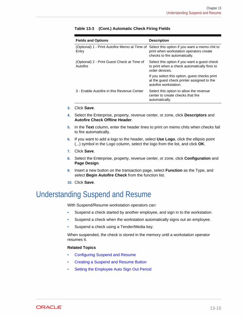
Table 13-3 (Cont.) Automatic Check Firing Fields
Fields and Options Description
(Optional) 1 - Print Autofire Memo at Time ofEntry
Select this option if you want a memo chit toprint when workstation operators createchecks to fire automatically.
(Optional) 2 - Print Guest Check at Time ofAutofire
Select this option if you want a guest checkto print when a check automatically fires toorder devices.
If you select this option, guest checks printat the guest check printer assigned to theautofire workstation.
3 - Enable Autofire in this Revenue Center Select this option to allow the revenuecenter to create checks that fireautomatically.
3. Click Save.
4. Select the Enterprise, property, revenue center, or zone, click Descriptors andAutofire Check Offline Header.
5. In the Text column, enter the header lines to print on memo chits when checks failto fire automatically.
6. If you want to add a logo to the header, select Use Logo, click the ellipsis point(...) symbol in the Logo column, select the logo from the list, and click OK.
7. Click Save.
8. Select the Enterprise, property, revenue center, or zone, click Configuration andPage Design.
9. Insert a new button on the transaction page, select Function as the Type, andselect Begin Autofire Check from the function list.
10. Click Save.
Understanding Suspend and ResumeWith Suspend/Resume workstation operators can:
• Suspend a check started by another employee, and sign in to the workstation.
• Suspend a check when the workstation automatically signs out an employee.
• Suspend a check using a Tender/Media key.
When suspended, the check is stored in the memory until a workstation operatorresumes it.
Related Topics
• Configuring Suspend and Resume
• Creating a Suspend and Resume Button
• Setting the Employee Auto Sign Out Period
Chapter 13Understanding Suspend and Resume
13-15
Configuring Suspend and Resume1. In the EMC, select the revenue center, click Setup and RVC Parameters.
2. Click the Options tab.
3. Select 60 - Enable Suspend/Resume.
4. Click Save.
5. Select the Enterprise, property, or zone, click Configuration and Tender/Media.
6. Insert a record with the tender name.
7. Double-click the tender record.
8. On the General tab, in the Key Type field, select 2 - Service Total.
9. Click the Options tab and the Ops Behavior sub tab.
10. Select 74 - Suspend Order.
11. Click Save.
Related Topics
• Understanding Suspend and Resume
Creating a Suspend and Resume ButtonTo allow workstation operators to manually suspend a check, you need to add a buttonassigned to the service total tender record.
1. In the EMC, select the Enterprise, property, revenue center, or zone, clickConfiguration and Page Design.
2. Open the Front of House page on which to place the Suspend/Resume button.
3. On the Edit tab, select the page area in which to define the Suspend/Resumebutton.
4. Click Button.
5. On the General sub-tab, enter the button name in the Legend field.
6. Select Tender/Media from the Type drop-down.
7. Click the black arrow directly beneath the Type drop-down, select the tender youcreated for the suspend and resume service total, and click OK.
8. Position and size the button on the page. Use the Style arrow to change the color.
9. Click Save.
Related Topics
• Understanding Suspend and Resume
Setting the Employee Auto Sign Out PeriodTo automatically suspend a check and sign out an employee, you need to define theautomatic operator popup interval.
Chapter 13Configuring Suspend and Resume
13-16

1. In the EMC, select the Enterprise, property, revenue center, or zone, click Setupand Control Parameters.
2. Click the Configuration tab.
3. In the Automatic Operator "Popup" Interval (min:sec) field, enter the amount oftime (in minutes and seconds) that the workstation waits before signing out aninactive popup workstation operator.
4. Click Save.
Related Topics
• Understanding Suspend and Resume
Understanding Follow MeFollow Me extends the functionality of the suspend and resume feature in Simphony.Follow Me allows workstation operators to use suspended checks across workstationsin the same revenue center. This feature increases speed of service in a typical puband fast casual restaurant environment.
For example, a pub may have three workstations and up to twelve bartenders workingsimultaneously. Each bartender can sign in and sign out on any workstation. Abartender can begin a check on workstation 1, prepare a drink, and then log on toworkstation 2 to resume the check. The check is suspended on workstation 1 andautomatically resumed on workstation 2. Any menu items, discounts, and servicecharges that were added on workstation 1 appear on workstation 2. A check can beopen on only one workstation at a time.
The journal logs the suspend and resume history of each check and lists theworkstation on which the suspend and resume transaction was performed.
Related Topics
• Configuring Follow Me Checks
Configuring Follow Me Checks1. In the EMC, select the revenue center, click Setup, RVC Parameters, and
Options.
2. Select 68 - Enable Follow Me.
When you set Follow Me, option 60 – Enable Suspend/Resume dims, and viceversa. You cannot select both Follow Me and Suspend/Resume; they are mutuallyexclusive. When you set Follow Me, each workstation in the revenue centerparticipates in the Follow Me operation.
3. Select the property, click Setup, and Workstations.
4. On the General tab, enter information in the fields as described in the followingtable:
Chapter 13Understanding Follow Me
13-17

Table 13-4 Workstation Timeout Settings
Timeout Setting Description
Check Inactivity Timeout The number of seconds the workstationwaits before prompting the workstationoperator to cancel a transaction. If you setthis value to 0 (zero), the Cancel dialogdoes not appear. If you select 68 - EnableFollow Me in the RVC Parameters module,the guest check is automatically suspendedrather than cancelled.
Check Inactivity Dialog Timeout The number of seconds the workstationshows the Do you need more time?Inactivity dialog before automaticallycancelling the transaction. If you set thisvalue to 0 (zero), the Cancel dialog does notappear.
5. Click Save.
Related Topics
• Understanding Follow Me
Order Handling on Open ChecksThis section describes how to configure Simphony to:
• Send orders to order devices (such as remote printers or a kitchen display system(KDS)) when performing a Service Total while the guest check remains open
• Manually or automatically send items on a guest check to order devices in groupsover a period of time at pre-set times
Related Topics
• Setting the Service Total to Send Items to be Prepared While the Check RemainsOpen
• Setting the Hold and Fire Option
• Setting the Hold and Fire Tender Notification
• Setting a Reminder for Items on Hold
• Setting Checks with Items on Hold to End Current Service Round
• Setting Check Handling with Held Items When Closing Checks
Holding and Sending Items to Order DevicesThe following table describes how to configure the workstation to hold and send menuitems on open guest checks to order devices.
Chapter 13Order Handling on Open Checks
13-18

Table 13-5 Configure Workstations to Hold Items on Guest Checks
Task More Information
Enable option to hold items on guest checksand add touchscreen buttons
Setting the Hold and Fire Option
Enable workstation notifications for heldmenu items when tendering
Setting the Hold and Fire Tender Notification
Configure workstations to remind workstationoperators of checks with items on hold aftersigning into the workstation
Setting a Reminder for Items on Hold
Configure guest checks with items on hold toend current service round and addtouchscreen buttons
Setting Checks with Items on Hold to EndCurrent Service Round
Configure how to handle items on hold whenclosing checks
Setting Check Handling with Items on Holdwhen Closing Checks
(Optional) Configure Check Screen Look Up(SLU) to display checks with only held items
Configuring Check Screen Lookup (SLU) toShow Checks with only Held Items
Setting the Service Total to Send Items to be PreparedWhile the Check Remains Open
1. In the EMC, select the property click Configuration and Tender/Media.
2. Insert a Service Total tender record if it does not exist.
3. Double-click the record to open it.
4. On the General tab, in the Key Type field, select 2 - Service Total.
5. Select the Options tab, and the Ops Behavior sub-tab.
6. Select option 95 - Send Order.
7. Click Save.
8. Add a touchscreen button for the tender/media record that you created in step 2. Workstation Touchscreen Pages contains more information about configuringtouchscreen buttons (for example, Service Total, Hold, Transaction Hold, TimedFire, and View Fire Times).
Related Topics
• Order Handling on Open Checks
Setting the Hold and Fire Option1. In the EMC, select the revenue center, click Setup, and RVC Parameters.
2. Select the Options tab, and then select 70 - Enable Hold and Fire.
3. Click Save.
Related Topics
• Order Handling on Open Checks
Chapter 13Setting the Service Total to Send Items to be Prepared While the Check Remains Open
13-19
Setting the Hold and Fire Tender Notification1. In the EMC, select the revenue center, click Setup, and Control Parameters.
2. Select the Options tab, and then select 66 - Enable Hold and Fire Final TenderNotification.
3. Click Save.
Related Topics
• Order Handling on Open Checks
Setting a Reminder for Items on Hold1. In the EMC, select the Enterprise level, click Setup and Control Parameters.
2. Click the Configuration tab.
3. In the Confirm Threshold Period for Items on Hold (minutes) field, enter thetime that should elapse before notifying workstation operators of checks with itemson hold.
If you set the Confirm Threshold Period for Items on Hold (minutes) to 0, theworkstation shows a reminder each time a workstation operator signs in to theworkstation.
4. Click Save.
Related Topics
• Order Handling on Open Checks
Setting Checks with Items on Hold to End Current ServiceRound
1. In the EMC, select the property, click Configuration and Tender/Media.
2. Insert a Hold Service Total tender record if it does not exist.
3. Double-click the record to open it.
4. On the General tab, in the Key Type field, select 2 - Service Total.
5. Select the Options tab, and the Ops Behavior sub-tab.
6. Select a Hold Type for the service total tender. The Hold Type is used with Holdand Fire to establish the order device output instruction for menu items on theguest check. The following options are available.
• 1 - Hold Order – Holds the entire guest check.
• 2 - Keep Held Status – Sends all items to the order device except those onhold.
• 3 - Fire Order – Sends all menu items, including items on hold, to orderdevices. Items that you configure to send at a preset time are exempt from thisservice total type.
Chapter 13Setting the Hold and Fire Tender Notification
13-20

7. Repeat Steps 2 through 6 to configure remaining hold service total tenders (forexample, Transaction Hold, Timed Fire, and View Fire Times).
8. Click Save.
9. Add touchscreen buttons for the tender/media records that you created in Step 2. Workstation Touchscreen Pages contains more information about configuringtouchscreen buttons (for example, Hold, Transaction Hold, Timed Fire, and ViewFire Times).
Related Topics
• Order Handling on Open Checks
Setting Check Handling with Held Items When ClosingChecks
1. In the EMC, select the property, click Configuration and Tender/Media.
2. Double-click a Service Total tender record to open it.
3. Select the Options tab and the Ops Behavior sub-tab.
4. Select a Hold Type for each type of Service Total tender used when making apayment and closing a guest check. The following table describes the Hold Typesand their affect on the workstation messages.
Table 13-6 Hold Types and Workstation Messages
Hold Type Workstation Message When Closing a Check withItems on Hold
1 - Hold Order Select this option to have the workstation show amessage asking the workstation operator whether tosend the items on hold to the order devices or to closethe check without sending the items.
2 - Keep Held Status Select this option to have the workstation show amessage asking the workstation operator whether tosend the items on hold to the order devices or to closethe check without sending the items.
3 - Fire Order Select this option to have the workstation send all itemson hold to the order devices. This is the default HoldType.
5. Click Save.
Related Topics
• Order Handling on Open Checks
Printing Multiple Languages on Guest Checks andCustomer Receipts
You can show guest check detail and print a receipt showing both primary andsecondary languages configured for the property. For example, English and Arabiccan appear on the guest check detail area and print on the same receipt. When
Chapter 13Setting Check Handling with Held Items When Closing Checks
13-21

configured, all areas of the check show both languages, except the check number,table number and employee name and number. These numerals print in the primarylanguage.
Related Topics
• Configuring Right to Left Reading Languages
• Creating a Print Language List Button
• Creating Print Language Buttons
Configuring Right to Left Reading LanguagesTo show guest check detail and print customer receipts and guest checks in the rightto left orientation configured for a language, set the following:
• Enterprise Language
• Workstation Language
• Secondary Print Language
1. In the EMC, select the Enterprise level, click Setup and Languages.
2. Double-click the language record to open it.
3. Select Right-To-Left to have the check detail area and customer receipt appear inOps and print in right-to-left orientation.
4. Click Save.
You can print custom numerals on a customer receipt or guest check. Forexample, Arabic digits can print on the receipt rather than Latin digits. Simphonyversion 2.7 and later does not support custom numerals in the Ops check detailappearance.
5. Select the property, click Setup, Workstations, and General.
6. Select the language you want to appear on the workstation from the Languagelist.
You can override the default language on the workstation for specific employeesusing the Employee Maintenance module. Employees with a different languageconfigured in Employee Maintenance see that language after signing in to theworkstation.
7. Click Save.
8. Select the property, click Setup, Property Parameters, and General.
9. Select primary and secondary languages from the Language 1 and Language 2lists.
10. Select the language from the Select Secondary Print Language list. Selecting 0 –None causes only the default language to print. When printing multiple languages,the system prints item names in the order configured for the property.
11. Click Save to apply the changes.
12. Select the Enterprise, property, revenue center, or zone, click Setup, FormatParameters, and Options.
13. Select 52 - Print Secondary Language on Guest Checks/Customer Receipt.
Chapter 13Configuring Right to Left Reading Languages
13-22
14. Click Save.
Related Topics
• Printing Multiple Languages on Guest Checks and Customer Receipts
Creating a Print Language List ButtonWhen printing multiple languages, you can have each workstation operator select thelanguage from a list in Ops using the Print Language List button.
1. In the EMC, select the Enterprise, property, revenue center, or zone, clickConfiguration and Page Design.
2. Add a button to the appropriate screen with the function Print Language List.
3. Click Save.
Related Topics
• Printing Multiple Languages on Guest Checks and Customer Receipts
• Workstation Touchscreen Pages
Creating Print Language ButtonsThe Print Language function allows the workstation operator to select a specificlanguage. For example, if the secondary language is Arabic, the Print Language 2button prints the customer receipt in Arabic. Follow these steps to create one or morePrint Language buttons.
1. In the EMC, select the Enterprise, property, revenue center, or zone, clickConfiguration and Page Design.
2. Add a button to the appropriate screen with the function Print Language 2.Depending on the number of languages, you can create other Print Languagebuttons (for example, Print Language 3 and Print Language 4).
3. Click Save.
Related Topics
• Printing Multiple Languages on Guest Checks and Customer Receipts
• Workstation Touchscreen Pages
Chapter 13Creating a Print Language List Button
13-23

14Resetting Daily Totals
A business day refers to the beginning and end times of a day of business. A businessday can have any begin time, but typically a business day starts in the early morninghours during a slow or closed period of operations (for example, 3:00 a.m. or 4:00a.m.). A calendar day always begins at 12:00 a.m.
To reset daily check and employee totals, a property or revenue center must start anew business day.
• Start of Day
• Start of Day Business Rules
• Start of Day with Offline Workstations or Server
• Configuring Start of Day
Related Topics
• Configuring Start of Day
Start of DayStart of Day (SOD) is the process that begins a new business day at a property. TheSOD can be set to run automatically or manually.
When the time of day occurs that a new business day is automatically configured tostart (for example, at 4:00 a.m. each day), the following actions occur in the orderlisted:
• Simphony increases the Business Day and updates the status of checks andemployees.
• The PC Autosequence runs, and typically performs the following actions:
– Batches and settles credit cards
– Runs custom applications for a property
• After the SOD Asequence completes, Simphony checks to see whether it is timeto run other autosequences (such as Start of Week Autosequence, Start of PayPeriod Autosequence, and so on).
Many properties like to start a new business day manually at their own time (after anight auditor balances reports). Often these properties stop their Simphony andproperty management systems at the same time, roll to a new business day, and thenbring the systems back up. An administrator can manually run SOD in Simphony usingan interaction called PC Autosequence (in the Enterprise Management Console(EMC)) or by pressing a button on the workstation. When SOD begins manually,Simphony performs the same actions as if it were run automatically. The onlydifference is the method by which SOD begins.
Related Topics
• Configuring Start of Day
14-1
Start of Day Business RulesSimphony has business rules to determine how and when a business day can begin,and which business day is beginning. The rules exist for both automatic and manualStart of Day (SOD).
When starting a new business day, the following rules apply:
• SOD cannot be run twice in 8 hours.
• SOD cannot be run twice between midnight and noon.
• SOD cannot be run twice between noon and midnight.
• When a business day is scheduled to run automatically, it is not possible to startthe business day manually with a PC Autosequence.
A business day is calculated based on noon (12:00 p.m.) to noon times.
• If SOD is run before noon, Simphony assumes the business day completed is forthe previous calendar day. (If SOD runs at 3:05 a.m. on the 17th, the 16th is thebusiness day that is closing, and the 17th is the business day being started.)
• If SOD is run after noon, Simphony assumes the business day completed is for thecurrent calendar day. (If SOD is run at 11:52 p.m. on the 17th, the 17th is thebusiness day that is closing, and the 18th is the business day being started.)
Related Topics
• Configuring Start of Day
Start of Day with Offline Workstations or ServerWorkstations are aware of the business date configuration so that offline reports showrelevant information. Consider the following scenario:
• Every business day begins at 3:00 p.m.
• On Tuesday at approximately 11:00 a.m., a property loses communication with thedatabase (the property is in Yellow Mode).
• The site is offline until Friday afternoon.
In this situation, workstations run reports as if Start of Day (SOD) occurred. Forexample, a report taken for today on Wednesday at 4:00 p.m, shows data fromWednesday at 3:00 a.m. (the time SOD would have occurred) to the current secondwhen the report was taken. In addition, if days are configured for manual SOD,workstation reports assume that the business day begins 24 hours after the previousSOD occurred. In this situation, a dialog box appears on workstations informing themanager that a new business day has begun.
Catch-Up mode increases the business day after the Simphony server goes offlineduring an automatically scheduled SOD time period. Consider the following scenario:
• SOD is set to run automatically at 4:00 a.m.
• At 2:00 a.m., the Simphony server experiences a power failure.
• At 6:00 a.m., the Simphony server is online again.
Chapter 14Start of Day Business Rules
14-2
In Catch-Up mode, the SOD Autosequence does not start. With Catch-Up mode, thebusiness day still starts at 4:00 a.m. When Simphony comes online at 6:00 a.m., thePERIOD_INSTANCE table is populated with rows to indicate that the business daystarted. The rows do not show a 6:00 a.m. run time, however. Catch-Up mode knowsthat the application was supposed to have started at 4:00 a.m., so the rows arecreated with 4:00 a.m. as the start time. Simphony can catch-up from up to two missedautomatic start of days and make the appropriate PERIOD_INSTANCE entries.
Related Topics
• Configuring Start of Day
Configuring Start of Day1. In the EMC, select the Enterprise level, click Configuration and Roles.
2. Select the role type (such as manager), click the Operations tab, and the PMCProcedures sub-tab.
3. Select the appropriate start of day role privileges:
• 30058 – Run Start of Day from OPS – Select this option to allow allemployees with the role to increment the business date from the property’sCheck and Posting Service (CAPS) workstation.
• 30059 – Prevent Running SOD from OPS with Open Checks – Select thisoption so that Start of Day (SOD) cannot run when open checks exist.
4. Click Save.
5. If you want to allow a manager or administrator to manually run SOD from aworkstation, select the Enterprise, property, or revenue center, clickConfiguration and Page Design.
If you do not want to allow manual SOD, skip to Step 14.
6. Select the page on which to place the Start of Day button. The Start of Day buttonallows a manager or administrator to manually run the Start of Day on aworkstation.
7. Add a Start of Day button:
a. In the Legend field, enter Run Start of Day.
b. In the Type field, select Function.
c. Click the arrow beneath the Type field and select Start of Day.
d. Position and size the new button on the page.
8. Click Save.
9. Select the property, and then click Setup, Property Parameters, and Options.
10. If you want to allow a manager or administrator to manually run SOD from aworkstation, select 48 – Run Start of Day from OPS.
11. Select the Calendar tab.
12. Select Run Manually for each day of the week.
13. In the Manual SOD Safety catch time field, set the time when the applicationautomatically increments the business date if someone forgets to manually runSOD.
Chapter 14Configuring Start of Day
14-3
The application checks to see whether SOD occurred within a 24-hour period forthe selected property. This time is based on the time zone of the property.
14. Click Save.
15. Select the Enterprise level, click Configuration and PC Autosequences.
16. Insert a PC Autosequence record and name it Increment Business Day.
17. Open the record and select the Allowed Properties to view the autosequence.
18. (Optional) Add Parameters as appropriate. For example, you can enter a propertynumber and exclude a revenue center number.
19. On the Steps tab, add a step and in the Step Type drop-down list, and select 3 –Increment Business Date.
20. Click Save.
Related Topics
• Resetting Daily Totals
• Start of Day
• Start of Day Business Rules
• Start of Day with Offline Workstations or Server
Chapter 14Configuring Start of Day
14-4

15Maintaining the Database
Simphony is a data driven solution that relies on configuration data stored in a centraldatabase. Transactions that are added on Simphony clients are also stored withindatabases.
Simphony is comprised of two sets of databases that are used for the followingpurposes:
• Online transaction processing
• Online analytical (reports) processing
Two processes move data between the database:
• Data Transfer Service (DTS) – Moves configuration data from the transactiondatabase to the analytical database
• Direct Posting Service (DPS) – Moves transaction data from the transactiondatabase to the analytical database
• Understanding the Database Update Frequency
• Setting the Database Update Frequency
• Understanding the Clear Totals Operation
• Running the Clear Totals Operation
Understanding the Database Update FrequencyYou can establish how often database synchronization jobs are run on theworkstations. By default, the workstations and Kitchen Display System (KDS)Controllers wait 30 minutes to retrieve the latest updates from the database.
The Database Update Frequency setting exists in three modules in the EnterpriseManagement Console (EMC):
• Property Parameters
• Workstations
• KDS Controller
The Workstations module setting or KDS Controller setting takes precedence over theProperty Parameters setting. If the workstation’s Database Update Frequency settingis greater than the Property Parameters setting, the highest configured value within theentire Workstations module for the property is used for the purge jobs eventscheduling calculation. For example, if the workstation’s Database Update Frequencyfield has a configured value of 180 seconds, an additional 30 minutes is added to theevent schedule. In other words, the Check and Posting Service (CAPS) totals purgejob does not run until 33 minutes have elapsed from the moment that the Clear Totalsbutton is first clicked.
15-1
Related Topics
• Setting the Database Update Frequency
Setting the Database Update Frequency1. In the EMC, select the property, click Setup and Property Parameters.
2. Click the Workstations tab.
3. In the Database Update Frequency field, enter the number of seconds thatworkstations and KDS Controllers wait to retrieve the latest updates from thedatabase.
4. Click Save.
5. If you want to override this setting for the workstation, select the property, clickSetup and Workstations.
6. Double-click the workstation.
7. On the General tab, set the Database Update Frequency timeout value.
8. Click Save.
9. If you want to override this setting for the KDS, select the property, click Setupand KDS Controllers.
10. Double-click the KDS record.
11. On the General tab, set the Database Update Frequency timeout value.
12. Click Save.
Related Topics
• Understanding the Database Update Frequency
Understanding the Clear Totals OperationIf you have the appropriate privileges, you can purge unwanted transaction totalsaccumulated during testing and training periods prior to going live. Clearing totalsimmediately purges the totals for all of the designated property’s revenue centers fromthe Enterprise. You cannot clear totals for individual revenue centers.
The Clear Totals operation performs the following tasks:
• Immediately purges the property’s transaction totals and check related data onand prior to the selected business date from the Enterprise
• Initiates a request to run a purge job for the reporting database (Oracle HospitalityReporting and Analytics Advanced) totals
• Purges the MRequest Queues data
• Purges the Journal log file data
• (Optional) Purges Cash Management data
After the Clear Totals operation begins, two data purging events are scheduled to runfor the following purge jobs:
• Check and Posting Service (CAPS) Database – This event runs first based on theDatabase Update Frequency setting, plus an additional 30 minutes. When the
Chapter 15Setting the Database Update Frequency
15-2
scheduled time is reached, the application purges the designated property’s CAPSdatabase.
• Workstation DataStore Data – This event runs second based on the DatabaseUpdate Frequency setting, plus an additional 45 minutes. When the scheduledtime is reached, the application purges the DataStore data from the designatedproperty’s workstations.
Related Topics
• Running the Clear Totals Operation
Running the Clear Totals OperationBefore clearing totals, you must batch and settle all credit card transactions dated priorto the specified business date. You cannot clear totals when unbatched credit cardsexist. Oracle recommends that you generate and save all credit card related reportsfrom either the Enterprise Management Console (EMC) or Oracle HospitalityReporting and Analytics for historical reference.
Time Zone synchronization between the Simphony application server and workstationsis important for the Clear Totals operation to work correctly. The Client ApplicationLoader (CAL) keeps the time settings on Simphony clients in sync with the Simphonyapplication server. Some devices do not use CAL for configuration, and these devicescan become out of sync with the Simphony application server. Therefore, beforerunning the Clear Totals operation, ensure that the time settings on non-CAL devicesare set to match the Simphony application server’s time settings as closely aspossible.
1. In the EMC, select the property, click Tasks and Clear Totals.
2. Select the Business Date from the drop-down list.
3. Click Clear Totals. The Result window shows the status of each purged job.
4. Select the property, click Setup and Workstations.
5. Look at the column named Totals Cleared Through, verify that the date and timeappears in the column for each workstation at the property.
6. Double-click the Check and Posting Service (CAPS) workstation and then click theService Host tab.
7. Verify that the date and time appears in the Totals Cleared Through column forthe CAPS workstation.
EGateway log files show the date and time a Clear Totals operation was performed.
Related Topics
• Understanding the Clear Totals Operation
Chapter 15Running the Clear Totals Operation
15-3

16Printers and Order Devices
Printers and ordering devices are critical types of hardware that allow communicationbetween the Front of House and other areas of a restaurant, such as the kitchen andbar.
An order device generally refers to hardware used to print orders that need to beprepared, such as hot and cold items that print in the kitchen, or alcoholic beveragesthat print at the bar. Often an order device is a roll printer, but it may also be a KitchenDisplay System (KDS) display. Remote printers and remote kitchen printers are oftenused interchangeably with order device.
• Understanding Print Controller
• Roll Printer
• Slip Printer
• Internet Protocol (IP) Printer
• Bluetooth Printer
• Oracle MICROS Mini Printer
• Configuring a Printer
• Logo Printing
• Uploading a Logo to Simphony
• Assigning a Logo to Guest Checks and Customer Receipts
• Order Receipt Layouts
• Configuring an Order Receipt Layout
• KDS Controller
• Configuring a KDS Controller
• Configuring a KDS Display
• Configuring the KDS Bump Bar
• KDS Bump Bar Functions
• Configuring KDS Course Overrides
• Configuring a Backup KDS Controller
• Upgrading an Order Device
• Upgrading the RDC Operating System
• Resetting the RDC Factory Settings
• Installing the KDS Client
• Configuring the Deployment Schedule to Install CAL on KDS
16-1
Understanding Print ControllerA Print Controller is a service that sends print jobs to a printer. Each Operations (Ops)process has a built-in Print Controller. A workstation typically acts as a Print Controller.When a workstation operator performs an action that causes a guest check, orderreceipt, or other printing type to print, the Ops process does not communicate directlywith the printer receiving the print job. Instead, the Ops process sends a message tothe Print Controller (usually a workstation) that controls the printer. This PrintController then receives notification that the print job succeeded or failed, and routesthe success or failure information back to the workstation that sent the print job.
Ensure that employees in a revenue center know which workstations act as PrintControllers for remote printers. This knowledge helps in troubleshooting printingproblems.
Oracle Hospitality recommends that you have both a primary printer and a backupprinter, and that primary and backup printers reside on two different Print Controllers.This configuration prevents a single point of failure from causing multiple remoteprinters to stop printing.
A single Print Controller can control multiple printers. For example, one workstationcan control the following printers:
• Local printer that is physically attached to the workstation (used for guest checksand customer receipts)
• Hot food printer that is a remote Ethernet kitchen printer (used for order receipts)
In this configuration, if the workstation loses power or network connectivity, otherworkstations cannot print to either of these printers. This is generally not a problembecause the print jobs print to the backup printer as appropriate.
In another example, one workstation can control the following printers:
• Local printer that is physically attached to the workstation
• Hot food printer that is a remote Ethernet kitchen printer
• Cold food printer that is a remote Ethernet kitchen printer and backs up the hotfood printer
Oracle Hospitality does not recommend this configuration. In this example, if theworkstation loses power or network connectivity, other workstations cannot print to anyof these printers. In this scenario, no order receipts print to the hot or cold printers inthe kitchen. Kitchen operations would likely be severely impacted.
Related Topics
• Configuring a Printer
Roll PrinterA roll printer uses a roll of paper as its source media. Thermal printers and impactprinters are two types of roll printers that you can use with Simphony.
Chapter 16Understanding Print Controller
16-2

Thermal Printer
A thermal printer does not use ink. Special thermal paper is provided for these printersto burn the text onto the paper. Thermal printers are primarily used as guest check andcustomer receipt printers. They are used infrequently in kitchens due to the heatreaction. Thermal printers are ideal in public areas as the printing operation is quiet.
Impact Printer
An impact printer is something of a retronym. All printers were impact printers prior tothe invention of the thermal printer. An impact printer is primarily used in kitchens toprint order receipts. Impact printers can print in black and red, and they can be usedwith two-ply paper.
Related Topics
• Configuring a Printer
Slip PrinterA slip printer does not contain paper. The workstation operator must add a piece (orslip) of paper per print job. Properties who use custom stationery (often containing acompany logo or other similar artwork) generally use slip printers for guest checks andcustomer receipts. Slip printers are also used for check endorsement printing. Theslips that are used by these printers are often called hard checks because they areusually made of card stock.
Related Topics
• Configuring a Printer
Internet Protocol (IP) PrinterAn IP printer communicates with the Print Controller through a computer network thatuses the Internet Protocol (IP) address for communication.
Related Topics
• Configuring a Printer
Bluetooth PrinterBluetooth printing refers to printing from an Oracle MICROS Tablet E-Series to awireless printer through the Bluetooth protocol.
There is a one-to-one relationship between a tablet and a Bluetooth printer. After youidentify and configure a Bluetooth printer in the Enterprise Management Console(EMC) and pair it with a specific Oracle MICROS Tablet E-Series as the PrintController Service Host, you cannot assign another Oracle MICROS Tablet E-Series tothe same Bluetooth printer.
Related Topics
• Configuring a Printer
Chapter 16Slip Printer
16-3

Oracle MICROS Mini PrinterThe Oracle MICROS Mini Printer attaches to the right side of the Oracle MICROS E-Series Base Station. It can print the following items:
• Guest Checks
• Customer Receipts
• Kitchen Display System (KDS) Runner Order Receipts
• Order Device Output
• Workstation Reports
The Oracle MICROS Mini Printer is a 32 column printer with paper that is 2 inches inwidth.
The Oracle MICROS Mini Printer does not have auto-cut capability; it has a serratededge to help tear the paper. Because of this, workstation operators need to have aslight delay occur to allow the opportunity to tear individual print jobs before printing asecond voucher or order receipt. Note the following configuration settings that canaffect a printing delay:
• Regardless of the credit card option setting 4 - Prompt Before Printing SecondVoucher (In the RVC Parameters module), the first print job occurs and then theworkstation operator receives a Print second voucher prompt message. Beforeresponding to the prompt, the workstation operator can tear the first print job andthen respond to the prompt by pressing either the Enter/Yes or Clear/No buttonson the Oracle MICROS Tablet E Series to continue with the second print job.
• You can assign employee time chit printers in the Workstation module. If youassign the Oracle MICROS Mini Printer (a non-auto-cut printer) as the Empl TimeChit Printer and the Empl Time Card Printer, the time chit prints and workstationoperators receive a Print Time Card prompt when clocking in and out on aworkstation. Before responding to the prompt, the delay affords workstationoperators the time to tear off the time chit. Workstation operators can respond tothe prompt by pressing either the Enter/Yes or Clear/No buttons on the OracleMICROS Tablet E Series to continue with the time card print job. If you assignanother printer (besides the Oracle MICROS Mini Printer) for either of theEmployee Time Chit or Employee Time Card printing jobs, workstation operatorsdo not receive a prompt as the print jobs print independently of each other.
You cannot attach the Oracle MICROS Mini Printer to a Sales Recording Module(SRM).
Related Topics
• Configuring a Printer
Configuring a Printer1. In the EMC, select the property, click Setup and Printers.
2. Insert a printer record and name the printer.
3. Double-click the printer record to open it in form view.
4. Select the Workstation from the drop-down list.
Chapter 16Oracle MICROS Mini Printer
16-4
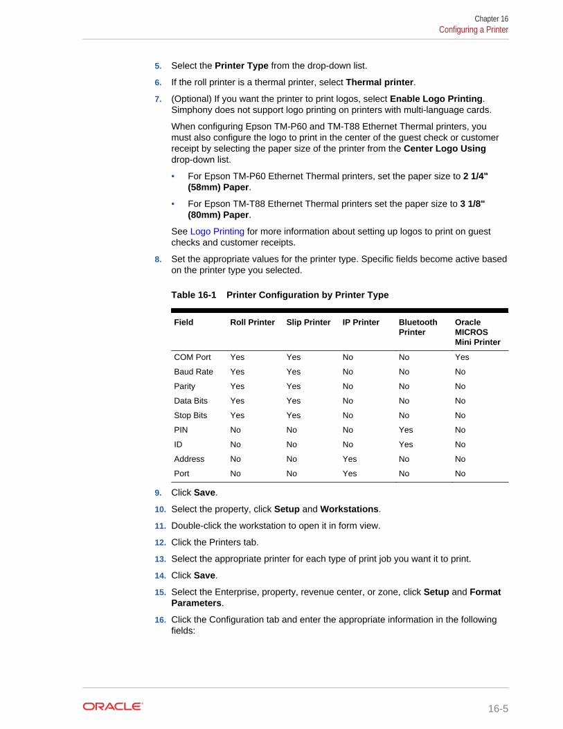
5. Select the Printer Type from the drop-down list.
6. If the roll printer is a thermal printer, select Thermal printer.
7. (Optional) If you want the printer to print logos, select Enable Logo Printing.Simphony does not support logo printing on printers with multi-language cards.
When configuring Epson TM-P60 and TM-T88 Ethernet Thermal printers, youmust also configure the logo to print in the center of the guest check or customerreceipt by selecting the paper size of the printer from the Center Logo Usingdrop-down list.
• For Epson TM-P60 Ethernet Thermal printers, set the paper size to 2 1/4"(58mm) Paper.
• For Epson TM-T88 Ethernet Thermal printers set the paper size to 3 1/8"(80mm) Paper.
See Logo Printing for more information about setting up logos to print on guestchecks and customer receipts.
8. Set the appropriate values for the printer type. Specific fields become active basedon the printer type you selected.
Table 16-1 Printer Configuration by Printer Type
Field Roll Printer Slip Printer IP Printer BluetoothPrinter
OracleMICROSMini Printer
COM Port Yes Yes No No Yes
Baud Rate Yes Yes No No No
Parity Yes Yes No No No
Data Bits Yes Yes No No No
Stop Bits Yes Yes No No No
PIN No No No Yes No
ID No No No Yes No
Address No No Yes No No
Port No No Yes No No
9. Click Save.
10. Select the property, click Setup and Workstations.
11. Double-click the workstation to open it in form view.
12. Click the Printers tab.
13. Select the appropriate printer for each type of print job you want it to print.
14. Click Save.
15. Select the Enterprise, property, revenue center, or zone, click Setup and FormatParameters.
16. Click the Configuration tab and enter the appropriate information in the followingfields:
Chapter 16Configuring a Printer
16-5

Table 16-2 Print Output Configuration
Field Description
Lines on First Page Enter the maximum number of lines to printon the first page of the guest check beforeprompting for a new check to begin a neworder receipt.
Lines on Other Pages Enter the maximum number of lines to printon successive pages of the guest checkbefore prompting for a new check to begin anew order receipt.
Line Feeds Before First Page Enter the number of lines to advance beforeprinting the guest check header. You canadd extra space for the check so it appearsproperly in custom check presentationbinders.
Line Feeds Before Other Pages Enter the number of lines to advance beforeprinting begins on the next successive page.
The line feeds set here are included in thenumber configured for the Lines on OtherPages field. For example, if you set this fieldto 5 and set Lines on Other Pages to 30, thepages have 25 lines of text.
Minimum Lines Per Roll Check/Receipt Enter the minimum number of lines to printon guest checks and customer receipts.Blank lines are added after printing toachieve the minimum.
Use this field if you want guest checks andcustomer receipts that are printed on a rollprinter to have a minimum length in order tofit into guest check covers.
Number of Guest Check Information Lines Enter the number of detail lines (0 through30) that can be entered in a SystemInterface Module (SIM) dialog box.
17. Click Save.
Related Topics
• Understanding Print Controller
• Roll Printer
• Slip Printer
• Internet Protocol (IP) Printer
• Bluetooth Printer
• Oracle MICROS Mini Printer
Logo PrintingYou can print the logo of your Enterprise, property, or revenue center on guest checksand customer receipts. Simphony only supports monochrome bitmap image files. UseMicrosoft Paint to convert an image to a monochrome bitmap. Adhere to the followingrules governing the size of your logo:
Chapter 16Logo Printing
16-6

• The image area must not exceed 98,304 pixels. (Keep in mind that a logo that is512 x 384 pixels exceeds 98,304 pixels.)
• The image width must not exceed 512 pixels.
• The image height must not exceed 384 pixels.
• The bitmap file must not exceed 8 kilobytes in size.
Simphony does not support logo printing on printers with multi-language cards.
Complete the following tasks to set up logo printing:
• Upload a logo to Simphony
• Assign a logo to guest checks and customer receipts
• Set the printer to print the logo
Related Topics
• Uploading a Logo to Simphony
• Assigning a Logo to Guest Checks and Customer Receipts
Uploading a Logo to Simphony1. In the EMC, select the Enterprise level, click Configuration and Print Logos.
2. Insert a new record and double-click it to open in form view.
3. Click Load Image.
4. Select the image and click Open to upload it to Simphony. After the logo uploads,an image preview appears.
5. Alternately, you can copy the image to your clipboard and click Paste Image toupload it to Simphony.
6. Click Save.
Related Topics
• Logo Printing
Assigning a Logo to Guest Checks and Customer Receipts1. In the EMC, select the Enterprise, property, revenue center, or zone, click
Descriptors and Guest Check Headers.
2. Select a check box in the Use Logo column.
If you select Use Logo for an existing record that has content in the Text column,that text no longer appears on printed guest checks and customer receipts.
3. Click the ellipsis button in the Logo column, select the image you uploaded, andclick OK.
4. Click Save.
5. If you want to assign the logo to customer receipts and guest check trailers, repeatthese steps but select the Guest Check Trailers and Customer ReceiptHeaders modules in Step 1.
Chapter 16Uploading a Logo to Simphony
16-7

You must also select 28 - Print Guest Check Trailer on Fast TransactionCustomer Receipt for tender records in the Tender/Media options. If you do notset this option, trailers do not print on customer receipts when the tender is used toclose a fast transaction.
6. Click Save.
Related Topics
• Logo Printing
Order Receipt LayoutsYou can configure the style of an order receipt (sometimes called a chit) that appearson a Kitchen Display System (KDS) Display. You can choose from a variety of layoutstyles to meet the customer requirements. Order receipt layouts generally fall into thecategories described in the following table:
Table 16-3 Order Receipt Layouts
Order Receipt Layout Description
Standard chits These chits do not show information (for example,seats or order types). They only show menu items.
Chits with seats These chits are used in revenue centers with seathandling.
Chits with order types These chits are used in revenue centers with ordertypes (for example, to distinguish between Dine-In andTake-Out orders).
Chits with seats and order types These chits are used in revenue centers where bothseat handling and order types are important to theoperations.
Lists The list views do not show individual chits. Each menuitem is listed on top of the next item (similar to aspreadsheet).
Related Topics
• Configuring an Order Receipt Layout
Configuring an Order Receipt Layout1. In the EMC, select the property, click Setup and KDS Displays.
2. Click the Display tab.
3. In the Chit Display Options section, select information in the following fields:
a. Click Select, select the KDS Chit Layout Style, and click OK. If you want tosee sample chit styles, click Help.
b. Select the Serpentine Mode:
• 0 - TSR – Select this mode to arrange the KDS with the number of verticalcolumns set in the Chit Columns field.
• 1 - Horizontal – Select this mode to arrange the KDS with the number ofhorizontal rows set in the Chit Rows field.
Chapter 16Order Receipt Layouts
16-8

• 2 - Vertical – Select this mode to arrange the KDS with the number ofvertical columns set in the Chit Columns field, and using the Chit Rowsfield to set the number of rows to appear.
c. In the Menu Item Font field, select the font size for menu items on the KDSDisplay.
d. In the Order Type Font field, select the font size for order type text on theKDS Display.
4. Click Save.
Related Topics
• Order Receipt Layouts
KDS ControllerA Kitchen Display System (KDS) Controller is a Windows service that controls KDSDisplays and performs other KDS-related functions. KDS Controllers move data to andfrom the KDS Displays. When an order is placed on a workstation, the KDS Controllerroutes the order to the appropriate KDS Display(s). When an order is bumped from aKDS Display, the KDS Controller routes the information about the order to thereporting database. Updates to KDS Displays (changing a Tool Bar or Bump Barbutton) are routed through the KDS Controller.
Related Topics
• Configuring a KDS Controller
• Configuring a KDS Display
• Configuring the KDS Bump Bar
• Configuring KDS Course Overrides
• Configuring a Backup KDS Controller
• KDS Bump Bar Functions
Configuring a KDS Controller1. In the EMC, select the property, click Setup and KDS Controllers.
2. Insert a new record, enter a record name, and double-click the new record.
3. On the General tab, configure the settings as described in the following table:
Table 16-4 KDS Controller Fields
Fields and Options Description
1 - Prevent Chit Bump on Expo Display ifChit Exists on Prep Display
Select this option to prevent a chit frombeing bumped from an Expo Display if thechit still exists on one of the Prep Displays.
Chapter 16KDS Controller
16-9
Table 16-4 (Cont.) KDS Controller Fields
Fields and Options Description
2 - Display Next Course after PreviousCourse Complete
If the property is using dining courses, selectthis option to show one course at a time onKitchen Display Systems (KDS). That is,menu items from course 2 appear on KDSDisplays only after menu items from course1 are bumped.
3 - Show Only Active Orders Select this option to allow a Speed ofService (SOS) Display to show only tablesthat have open orders.
4 - Expo-only Items Display as Done Select this option to change the status ofmenu items that do not go to Prep Stationsto Done when they fire.
5 - Exclude CAL Updates from Service HostChange
If the property does not use the ClientApplication Loader (CAL), select this optionto exclude updates to CAL for Service Hostchanges made in the KDS Controller.
6 - Enable Item Started Timings If the KDS is not using Dynamic Order Mode(DOM) and is configured to show every itemin an order on separate chits (select OrderDevices module option 3 - Single Item PerSub-Order), select this option to have theapplication recalculate an order’s targetdone time (TDT) when the kitchen staffstarts on the item with the longest prep time.
After the application recalculates the TDT,the system adjusts all of the fire times forthe remaining items (based on individualprep times) to ensure that all items completeat the new TDT.
7 - Include Theme In The Device Name Select this option to have the KDS Displaythe current Kitchen Theme after the name ofthe device on the KDS status bar.
8 - Enable load balancing Select this option to turn on KDS loadbalancing for the KDS Controller.
Load balancing distributes new orders toKDS Prep Stations based on which stationhas the least number of items. KDS PrepStations are assigned to distribution groupsand orders route to the KDS Prep Stationwith the fewest un-bumped menu itemswithin a distribution group.
9 - Enable Backup Controller AutomaticTakeover
If the KDS Controller has a backup servicehost, select this option to allow the backupKDS Controller to take over automaticallywhen the primary controller is down.
Database Update Frequency Enter the number of seconds you want theKDS Controller to wait to retrieve the latestupdates from the database.
Chapter 16Configuring a KDS Controller
16-10
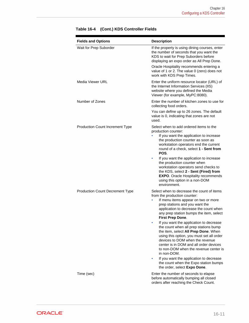
Table 16-4 (Cont.) KDS Controller Fields
Fields and Options Description
Wait for Prep Suborder If the property is using dining courses, enterthe number of seconds that you want theKDS to wait for Prep Suborders beforedisplaying an expo order as All Prep Done.
Oracle Hospitality recommends entering avalue of 1 or 2. The value 0 (zero) does notwork with KDS Prep Times.
Media Viewer URL Enter the uniform resource locator (URL) ofthe Internet Information Services (IIS)website where you defined the MediaViewer (for example, MyPC:8080).
Number of Zones Enter the number of kitchen zones to use forcollecting food orders.
You can define up to 26 zones. The defaultvalue is 0, indicating that zones are notused.
Production Count Increment Type Select when to add ordered items to theproduction counter:• If you want the application to increase
the production counter as soon asworkstation operators end the currentround of a check, select 1 - Sent fromPOS.
• If you want the application to increasethe production counter whenworkstation operators send checks tothe KDS, select 2 - Sent (Fired) fromEXPO. Oracle Hospitality recommendsusing this option in a non-DOMenvironment.
Production Count Decrement Type Select when to decrease the count of itemsfrom the production counter:• If menu items appear on two or more
prep stations and you want theapplication to decrease the count whenany prep station bumps the item, selectFirst Prep Done.
• If you want the application to decreasethe count when all prep stations bumpthe item, select All Prep Done. Whenusing this option, you must set all orderdevices to DOM when the revenuecenter is in DOM and all order devicesto non-DOM when the revenue center isin non-DOM.
• If you want the application to decreasethe count when the Expo station bumpsthe order, select Expo Done.
Time (sec) Enter the number of seconds to elapsebefore automatically bumping all closedorders after reaching the Check Count.
Chapter 16Configuring a KDS Controller
16-11

Table 16-4 (Cont.) KDS Controller Fields
Fields and Options Description
Check Count Enter the number of checks that are allowedto appear on the KDS before automaticallybumping.
4. Click the Service Host tab.
5. Click Select adjacent to the Service Host field, select a service host from the list,and click OK.
6. (Optional) Click Backup Service Host and configure a backup KDS Controller. Configuring a Backup KDS Controller contains more information about how toconfigure a backup KDS Controller.
7. (Optional) Click Item Status Colors and select the colors in which you want itemsto appear on KDS Expo Displays when the status of items change. The followingtable describes the Item Status Color fields.
Table 16-5 Item Status Colors Fields
Field Description
Status Sent Color Select in which color items appear whenworkstation operators send orders to theKDS.
Status Fired Color Select in which color items appear whenthey fire to the Prep Display.
Status Bumped Color Select in which color items appear whenthey are bumped from the Prep Display.
Status Started Color Select in which color items appear whenthey are Prep started.
This feature only functions with KDS Prepstations, in non-DOM Mode, and with ItemStarted Timings deactivated.
Item Select Color Select in which color items show whenkitchen staff selects an item on the order.
Item Mark Color Select in which color items appear whenkitchen staff places items on hold.
Item Recall Color Select in which color items appear whenkitchen staff recalls an order.
Item Recallable Color Select in which color recallable itemsappear.
8. Click Save.
9. Select the property, click Setup and RVC Configuration.
10. Double-click the revenue center for which you want to assign the KDS Controller.
11. On the General tab, select the KDS Controller.
12. Click Save.
Related Topics
• KDS Controller
Chapter 16Configuring a KDS Controller
16-12

• KDS Bump Bar Functions
Configuring a KDS Display1. In the EMC, select the property, click Setup and KDS Displays.
2. Insert a new record, enter a name for the KDS Display, and double-click the newKDS Display record.
If you are configuring a Windows 32 KDS Display, append the prefix WSKDSD tothe KDS Display name, for example, WSKDSDISPLAY1. Do not include a spacebetween the prefix and the display name.
3. Select the KDS Controller for the display and enter the IP Address of the display.
4. Select a KDS Tool Bar and a Bump Bar.
5. Select the appropriate platform of the KDS Display:
• If the KDS is PC-based, select 0 - PC-based.
• If you are using an OASYS KDS Display, select 1 - SEI OASYS.
6. If you selected 1 - SEI OASYS in Step 5, select the Card ID or slot number of theSEI card in the OASYS box and the Video ID to identify the KDS Display.
7. From the Display Orientation drop-down list, select the orientation type for thedisplay.
8. Select option 1 - Enable Item Select.
9. If the display is a Speed of Service (SOS) Display, select the appropriate optionsas described in the following table:
Table 16-6 SOS Display Options
Option Description
2 - Only Active Tables Select this option to show only tables thatare currently active on the display.
3 - Dynamic Display Select this option to turn on the DynamicDisplay feature.
4 - Display Zone Select this option to show KDS zones(collection points) on the display. This optiononly becomes active if you select 3 -Dynamic Display.
5 - Display Rvc Separator Select this option to separate orders byrevenue center. This option only becomesactive if you select 3 - Dynamic Display.
10. Click the Display tab.
11. Configure the Display Screen Options as described in the following table:
Chapter 16Configuring a KDS Display
16-13
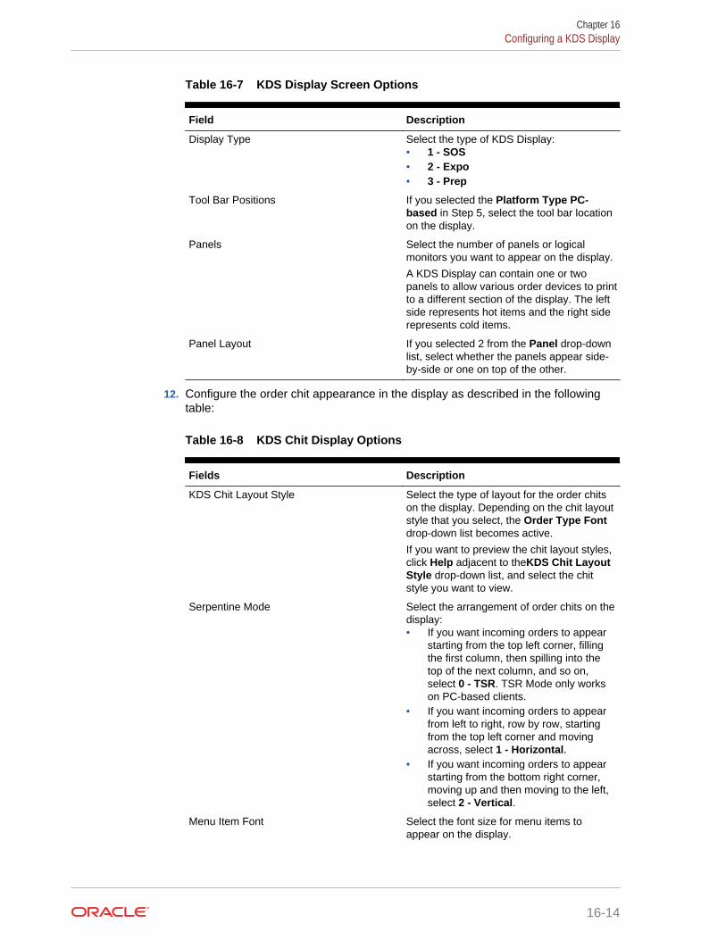
Table 16-7 KDS Display Screen Options
Field Description
Display Type Select the type of KDS Display:• 1 - SOS• 2 - Expo• 3 - Prep
Tool Bar Positions If you selected the Platform Type PC-based in Step 5, select the tool bar locationon the display.
Panels Select the number of panels or logicalmonitors you want to appear on the display.
A KDS Display can contain one or twopanels to allow various order devices to printto a different section of the display. The leftside represents hot items and the right siderepresents cold items.
Panel Layout If you selected 2 from the Panel drop-downlist, select whether the panels appear side-by-side or one on top of the other.
12. Configure the order chit appearance in the display as described in the followingtable:
Table 16-8 KDS Chit Display Options
Fields Description
KDS Chit Layout Style Select the type of layout for the order chitson the display. Depending on the chit layoutstyle that you select, the Order Type Fontdrop-down list becomes active.
If you want to preview the chit layout styles,click Help adjacent to theKDS Chit LayoutStyle drop-down list, and select the chitstyle you want to view.
Serpentine Mode Select the arrangement of order chits on thedisplay:• If you want incoming orders to appear
starting from the top left corner, fillingthe first column, then spilling into thetop of the next column, and so on,select 0 - TSR. TSR Mode only workson PC-based clients.
• If you want incoming orders to appearfrom left to right, row by row, startingfrom the top left corner and movingacross, select 1 - Horizontal.
• If you want incoming orders to appearstarting from the bottom right corner,moving up and then moving to the left,select 2 - Vertical.
Menu Item Font Select the font size for menu items toappear on the display.
Chapter 16Configuring a KDS Display
16-14
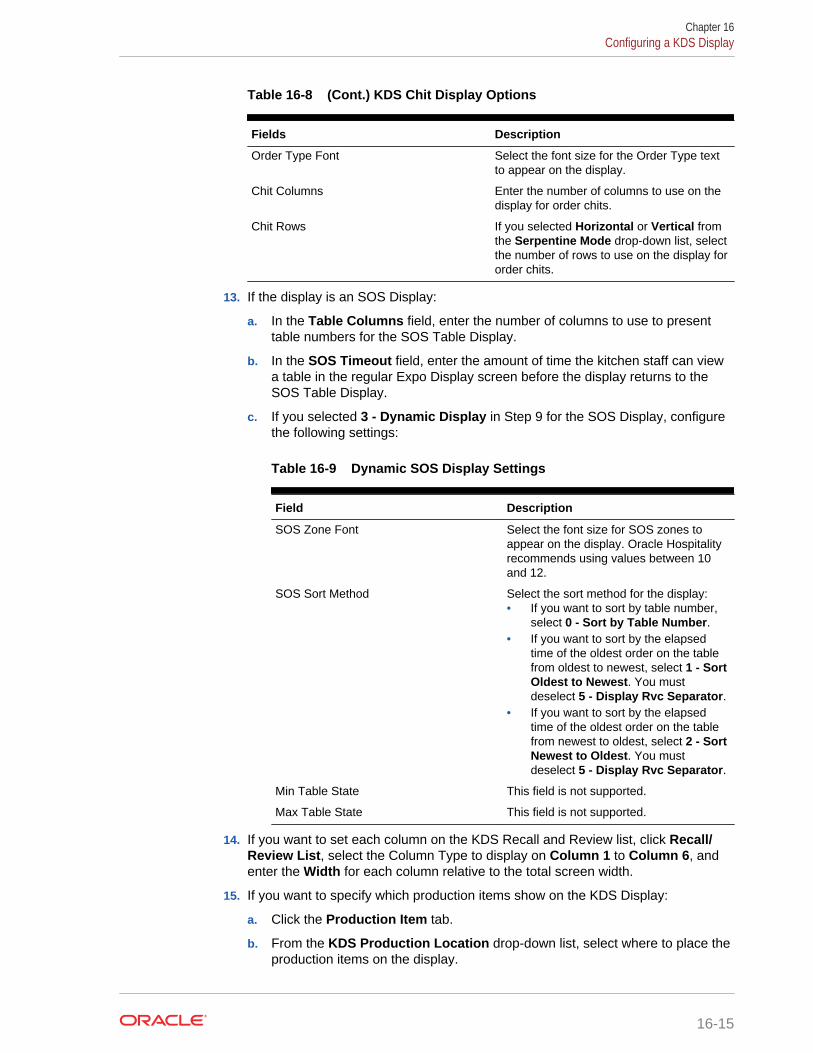
Table 16-8 (Cont.) KDS Chit Display Options
Fields Description
Order Type Font Select the font size for the Order Type textto appear on the display.
Chit Columns Enter the number of columns to use on thedisplay for order chits.
Chit Rows If you selected Horizontal or Vertical fromthe Serpentine Mode drop-down list, selectthe number of rows to use on the display fororder chits.
13. If the display is an SOS Display:
a. In the Table Columns field, enter the number of columns to use to presenttable numbers for the SOS Table Display.
b. In the SOS Timeout field, enter the amount of time the kitchen staff can viewa table in the regular Expo Display screen before the display returns to theSOS Table Display.
c. If you selected 3 - Dynamic Display in Step 9 for the SOS Display, configurethe following settings:
Table 16-9 Dynamic SOS Display Settings
Field Description
SOS Zone Font Select the font size for SOS zones toappear on the display. Oracle Hospitalityrecommends using values between 10and 12.
SOS Sort Method Select the sort method for the display:• If you want to sort by table number,
select 0 - Sort by Table Number.• If you want to sort by the elapsed
time of the oldest order on the tablefrom oldest to newest, select 1 - SortOldest to Newest. You mustdeselect 5 - Display Rvc Separator.
• If you want to sort by the elapsedtime of the oldest order on the tablefrom newest to oldest, select 2 - SortNewest to Oldest. You mustdeselect 5 - Display Rvc Separator.
Min Table State This field is not supported.
Max Table State This field is not supported.
14. If you want to set each column on the KDS Recall and Review list, click Recall/Review List, select the Column Type to display on Column 1 to Column 6, andenter the Width for each column relative to the total screen width.
15. If you want to specify which production items show on the KDS Display:
a. Click the Production Item tab.
b. From the KDS Production Location drop-down list, select where to place theproduction items on the display.
Chapter 16Configuring a KDS Display
16-15

• If you want production items to appear above the order chit, select 1 -Top.
• If you want production items to appear below the order chit and above theKDS toolbar (if used), select 2 - Bottom.
c. From the KDS Production Columns drop-down list, select the number ofproduction items that you want to show per line or production bar. Whenpossible, the KDS displays the maximum number of items in each bar. If thereare not enough items to fill the last bar, the remaining items are evenlydistributed across the line.
d. In the Production Items section, click Add and select a production item toappear on the KDS. Repeat this step until all of the production items to displayon the KDS appear in the list.
16. Click Save.
Related Topics
• KDS Controller
• KDS Bump Bar Functions
Configuring the KDS Bump BarKDS bump bars are physical devices attached to KDS displays. Bump bars are usedto select and bump orders. Additionally, you can program KDS bump bars to performother functions.
1. In the EMC, select the Enterprise, property, or zone, click Setup and KDS BumpBars.
2. Insert a KDS Bump Bar record if it does not exist.
3. Double-click the record to open it.
4. To configure the KDS bump bar with Oracle Hospitality default Scancode Valuesand Functions, click Create Default.
5. To configure the KDS bump bar with specific Scancode Values and Functions,click Add and then follow these steps:
a. Enter the Scancode Value of the button. The bump bar manufacturer sets theScancode Value.
b. Select the corresponding Function.
c. Continue to add all appropriate KDS bump bar functions. KDS Bump BarFunctions contains a list of the KDS bump bar functions.
6. Click Save.
Related Topics
• KDS Controller
• KDS Bump Bar Functions
Chapter 16Configuring the KDS Bump Bar
16-16

KDS Bump Bar FunctionsTable 16-10 KDS Bump Bar Functions
Function Description
Arrow up In list mode, the KDS display moves up to the next line
Arrow down In list mode, the KDS display moves down to the next line
Arrow left In chit mode, the KDS display moves one chit at a time to theleft
Arrow right In chit mode, the KDS display moves one chit at a time to theright
Cancel Exit the transaction
Close Close the KDS application
Done Mark an order as complete and remove the chit from thescreen
Done Item Mark an item on the chit as complete
End Move to the last page of the KDS display
Home Move to the first page of the KDS display
Mark Hold an order
Mark Item Hold an item in an order
Media Viewer View media files:• Related to the items in an order• On recipe preparations or other work-related tasks
Minimize Minimize the KDS application to the toolbar (MicrosoftWindows 32-bit displays)
Order Started Mark an order as started
Order Started First Mark the first order on the current page as started
Page down Scroll down the page
Page up Scroll up the page
Page left Scroll to the previous page
Page right Scroll to the next page
Prep Start/Stop Change an item’s status to start for the Prep Station (only forsingle item per sub-order chits (SIPS))
Production Summary View a list of all production items in the kitchen
Pull Order Pull an order from another KDS Prep Station in the PrepStation’s primary distribution group
Push Order Push an order to another KDS Prep Station in the revenuecenter
Recall Last Item Recall the last order marked as complete and restart thetimer
Recall Recall an order from the 50 orders marked as completeduring the last 15 minutes and restart the timer
Recall Item Recall an item marked as complete
Recall Last Item Recall the last item marked as complete
Chapter 16KDS Bump Bar Functions
16-17
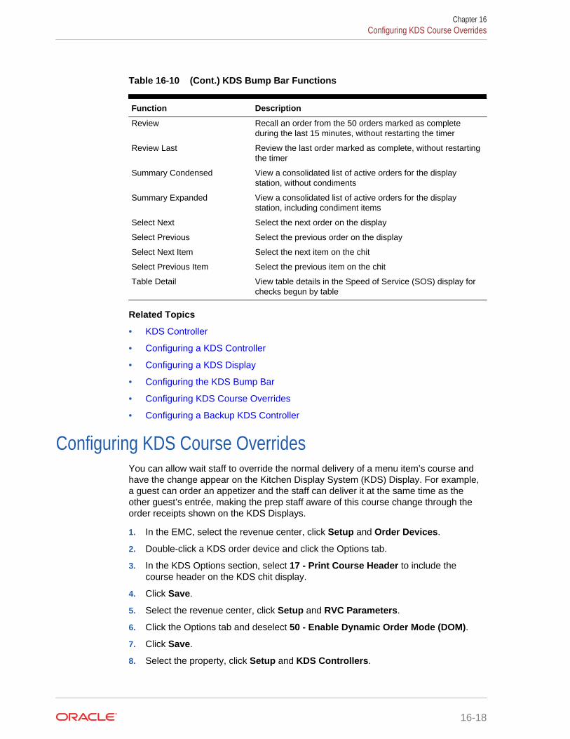
Table 16-10 (Cont.) KDS Bump Bar Functions
Function Description
Review Recall an order from the 50 orders marked as completeduring the last 15 minutes, without restarting the timer
Review Last Review the last order marked as complete, without restartingthe timer
Summary Condensed View a consolidated list of active orders for the displaystation, without condiments
Summary Expanded View a consolidated list of active orders for the displaystation, including condiment items
Select Next Select the next order on the display
Select Previous Select the previous order on the display
Select Next Item Select the next item on the chit
Select Previous Item Select the previous item on the chit
Table Detail View table details in the Speed of Service (SOS) display forchecks begun by table
Related Topics
• KDS Controller
• Configuring a KDS Controller
• Configuring a KDS Display
• Configuring the KDS Bump Bar
• Configuring KDS Course Overrides
• Configuring a Backup KDS Controller
Configuring KDS Course OverridesYou can allow wait staff to override the normal delivery of a menu item’s course andhave the change appear on the Kitchen Display System (KDS) Display. For example,a guest can order an appetizer and the staff can deliver it at the same time as theother guest’s entrée, making the prep staff aware of this course change through theorder receipts shown on the KDS Displays.
1. In the EMC, select the revenue center, click Setup and Order Devices.
2. Double-click a KDS order device and click the Options tab.
3. In the KDS Options section, select 17 - Print Course Header to include thecourse header on the KDS chit display.
4. Click Save.
5. Select the revenue center, click Setup and RVC Parameters.
6. Click the Options tab and deselect 50 - Enable Dynamic Order Mode (DOM).
7. Click Save.
8. Select the property, click Setup and KDS Controllers.
Chapter 16Configuring KDS Course Overrides
16-18
9. Double-click a KDS controller and select 2 - Display Next Course after PreviousCourse Complete.
10. Enter 2 in the Wait for Prep Suborder field.
11. Click Save.
12. Select the Enterprise, property, revenue center, or zone, click Configuration andMenu Item Maintenance.
13. Add condiment menu items for courses with the following names (or use similarnames):
• As Appetizer
• As Entrée
14. Click Save.
15. Select the Enterprise, property, revenue center, or zone, click Configuration andMenu Item Classes.
16. Add menu item classes for courses with the following names (or use similarnames):
• As Appetizer
• As Entrée
17. Add condiment menu item classes to apply course name overrides as necessary.
18. For each new condiment menu item class, select the following options:
• 2 - ON = Condiment Menu Items; OFF = Regular Menu Items
• 8 - Allow Menu Items in this Class to be Non-Priced
• 45 - Use KDS/Dining Course Number
• 46 - Override KDS Course Number of Parent Class
19. Click the General tab, select the appropriate KDS/Dining Course for each menuitem class, and click Save.
20. Select the Enterprise, property, revenue center, or zone, click Configuration andPrint Classes.
21. Create print class records that output to all appropriate KDS Displays.
22. Click Save.
Related Topics
• KDS Controller
• KDS Bump Bar Functions
Configuring a Backup KDS Controller1. In the EMC, select the property, click Setup and KDS Controllers.
2. Double-click the KDS Controller for which you want to assign a backup KDSController, and click Backup Service Host.
3. Click Select adjacent to the Service Host field, select a backup service host fromthe list and click OK.
4. Click Save.
Chapter 16Configuring a Backup KDS Controller
16-19

5. If you want the backup KDS Controller to automatically take over when the primaryKDS Controller is down, click General and select 9 - Enable Backup ControllerAutomatic Takeover.
6. Select the Enterprise level, click Configuration and Roles.
7. Double-click an employee role, click Operations and PMC Procedures.
8. Select 30057 - Backup/Restore KDS Controller, and click Save.
9. Select the Enterprise, property, revenue center, or zone, click Configuration andPage Design.
10. Insert a new button on the transaction page, select Function in the Type drop-down list, and select Restore Primary KDS.
This touchscreen button allows workstation operators to activate the primary KDSController that the current revenue center is using when it comes back online, ifthe backup KDS Controller is currently active.
11. If you did not configure the backup KDS Controller to automatically take over forthe primary KDS Controller, insert another new button on the transaction page.
a. Select Function in the Type drop-down list.
b. Select Active Backup KDS.
12. Click Save.
Related Topics
• KDS Controller
• KDS Bump Bar Functions
Upgrading an Order DeviceYou might need to upgrade the Remote Display Controller (RDC) in order to runKitchen Display System (KDS) version 2.1. This is available with Simphony version 2.3and later.
There are two RDC models (GX and LX) and each model has a different platform. Thepart number on the RDC indicates the model. The RDC Platform Update is version4.2.2.0 and it can automatically identify which model of RDC is being used and installthe correct files.
Upgrading an order device consists of completing the following tasks:
• Upgrading the operating system to the required platform
• Resetting factory settings
• Installing the KDS Client
Related Topics
• Upgrading the RDC Operating System
• Resetting the RDC Factory Settings
• Installing the KDS Client
Chapter 16Upgrading an Order Device
16-20

Upgrading the RDC Operating SystemThe RDCPlatformUpdate.zip file consists of two self-extracting zip files that are to beexecuted on an existing Client Application Loader (CAL) server.
1. Run the CALClientUpdate(4.1.3.66).exe.
This is a self-extracting zip file that contains the updated CAL client for bothRemote Display Controller (RDC) models (GX and LX). This executable filecreates the CAL package on the CAL server to deploy the CAL client to the RDC.
This is the same version of CAL client that ships with newer RCDs, so you maynotice that the CAL package does not appear to update some RDCs.
2. Run the ClientOSUpdate(4.2.2.0).exe. Each of these CAL packages restarts theRDC several times during the update.
This is a self-extracting zip file that contains the updated RDC operating systemimage for both RDC models (GX and LX). This executable file creates the CALpackage on the CAL server to deploy the operating system update to the RDC.
Related Topics
• Upgrading an Order Device
Resetting the RDC Factory SettingsPrevious configuration data on the device might interfere with the new platform andsoftware. To facilitate the best possible upgrade, return the unit to the factory settingsprior to loading the new Kitchen Display System (KDS) software.
1. On the Remote Display Controller (RDC), select Start, Settings, and ControlPanel.
2. Click the Default Settings tab.
3. Select the Reset to Default Settings option, and click Yes.
4. Save the settings. The device restarts after resetting the configuration.
5. Set the current date and time on the unit.
If the date and time on the unit do not match that of the server, the ClientApplication Loader (CAL) software does not work properly. Typically, the propertylist fails to load when these values are not correct.
6. Set the Internet Protocol (IP) address of the RDC to be a static value that works onthe network. Some units cannot pick up a Dynamic Host Configuration Protocol(DHCP) issued IP address after the upgrade.
a. To test the network configuration, open Internet Explorer on the RDC.
b. Enter the Uniform Resource Locator (URL) to the Simphony Egateway servicethat is hosting the CAL server (for example, http://[http://:8050/egateway/egateway.asmx]). If you can access this URL, the network is ready to connectto the server.
The unit does not require Domain Name System (DNS) or Windows InternetName Service (WINS) entries.
Chapter 16Upgrading the RDC Operating System
16-21

Related Topics
• Upgrading an Order Device
Installing the KDS ClientFollow the Kitchen Display System (KDS) instructions to install and configure the KDSclient software.
1. If type with a keyboard and nothing appears in the fields, press F12 and try again.
2. When selecting the Remote Display Controller (RDC) from the list:
a. Ensure that the Automatic DHCP Address is turned off.
b. Ensure that there are values in the Netmask and Default Gateway fields.
c. Ignore the value in the Select Product to Install on Workstation field.
Related Topics
• Upgrading an Order Device
Configuring the Deployment Schedule to Install CAL on KDS1. Select the Enterprise, click Setup, and then click CAL Packages.
2. Expand WS KDS Display from the left pane, and then select the latest KDS CALpackage.
3. Click the Deployment Schedule tab, and then click Add Deployment.
4. Select 1- Property/ Enterprise as the Deployment Type, select a Property, andthen select 0 - Install as the Action to Take.
5. If the property has Microsoft Windows 32 clients that are not configured as KDSDisplays:
a. Click Add Deployment again, and then select 2 - Specific Service Host asthe Deployment Type.
b. In the Service Host column, click the ellipsis (...) point button, select aMicrosoft Windows 32 workstation client that is not a KDS Display, and thenclick OK.
c. Select 1 - Skip as the Action to Take.
d. Repeat Steps 5-a through 5-c for all Microsoft Windows 32 clients that are notKDS Displays.
6. Click Save.
Chapter 16Installing the KDS Client
16-22

17Peripheral Devices
Peripheral devices connect with and relay information to or from Simphony. Forexample, common POS peripheral devices include magnetic card readers, cashdrawers, coin dispensers, printers, pole displays, and scales.
• Assigning and Unassigning a Cash Drawer
• Configuring a Cash Drawer
• Coin Dispenser
• Configuring a Coin Dispenser
• Magnetic Stripe Reader
• Installing the MSR Sleeve for Oracle MICROS Tablet E-Series 8-Inch and 11-InchDevices
• Configuring a Magnetic Stripe Reader
• Testing the MSR Sleeve for Oracle MICROS Tablet E-Series 8-Inch and 11-InchDevices
• Barcode Reader Setup Methods
• Configuring a Barcode Reader Using the Barcodes Module Method
• Configuring a Barcode Reader Using the Number Lookup (NLU) Method
• Fingerprint Scanning
• Configuring the Biometrics CAL Package Deployment
• Configuring Employee Privileges for the Fingerprint Reader
• Setting the Front of House to Assign Employee Personal Identification Number(PIN)
• Configuring the Workstation Employee Fingerprint Sign In Options
• Scanning a Fingerprint
• Configuring a Scale
Assigning and Unassigning a Cash DrawerYou can assign a cash drawer in the following ways:
• By Workstation
• By Workstation Operator
Giving multiple employees access to a single cash drawer is less secure than requiringemployees to be assigned to a cash drawer.
When you set the option Assign Cash Drawer By User Workstation in theWorkstations module, workstation operators can assign themselves to a cash drawerusing the one of the following function keys:
17-1
• 848 - Assign Cash Drawer
• 839 - Assign Cash Drawer 1
• 840 - Assign Cash Drawer 2
The following table compares these function keys:
Table 17-1 Assign Cash Drawer Function Key Comparison
848 - Assign Cash Drawer 839 - Assign Cash Drawer 1 and 840 -Assign Cash Drawer 2
Assigns the drawer to the workstation operatorwho is signed in.
Assigns the drawer to the workstation operatorwho is signed in.
If two drawers are used with the workstation,the application assigns drawer 1 if both areunassigned. If drawer 1 is assigned, theapplication assigns drawer 2, and vice-versa.
If two drawers are used with the workstation,these keys allow the workstation operator toselect the drawer he or she wants to assign.(To offer a choice, you must configure bothkeys on the touchscreen.)
Using this key opens the cash drawer. Using this key does not open the cash drawer.
If the cash drawer is unassigned, using thiskey prompts the workstation operator to assignthe cash drawer number.
If the cash drawer is unassigned, using thiskey prompts the workstation operator to assignthe cash drawer number, while the top of thescreen shows INACTIVE (no one is assigned).
If a workstation operator attempts to assignthe drawer when another workstation operatoris already assigned, the following errormessage appears: All Cash Drawers CurrentlyAssigned.
If the workstation operator attempts to assignthe drawer when another workstation operatoris already assigned, no error messageappears. The top of the screen show NAME(of the person assigned to the drawer). Thus,one person may assign the drawer andoverride the workstation operator who isalready assigned.
All workstation operators can use this functionkey.
All workstation operators cannot use thisfunction key.
At the end of a shift, the workstation operatoror a privileged manager needs to unassign thedrawer to allow another workstation operatorto use the drawer.
At the end of a shift, it is not necessary tounassign the drawer because anotherworkstation operator may override theassigned workstation operator.
The 849 - Unassign Cash Drawer function key unassigns the drawer from theworkstation operator, regardless of whether the workstation operator assigned thedrawer using function 848 or 839/840. All workstation operators can always unassignthemselves from a drawer. You can prevent this by removing the Unassign CashDrawer function key from the touchscreen or restrict its access using a lockout macro.
Related Topics
• Configuring a Cash Drawer
Configuring a Cash Drawer1. In the EMC, select the property, click Setup and Workstations.
2. Double-click the workstation to be used with the cash drawer.
3. Click the Transactions tab.
Chapter 17Configuring a Cash Drawer
17-2

4. Select the number of Cash Drawers (0, 1, or 2) that are physically installed at theworkstation.
5. In the Cash Drawer Beep Timeout field, enter the number of seconds the cashdrawer can be open before the workstation begins beeping. If you set this value to0 (zero), no beeping occurs.
6. In the Cash Drawer Notify Timeout field, enter the number of seconds the cashdrawer can be open before the workstation posts a message to the journal log file.If you set this value to 0 (zero), no message posts to the journal log.
7. Click the Options tab and the Hardware/Cash Drawer sub-tab.
8. Select the appropriate cash drawer options.
Table 17-2 Cash Drawer Workstation Options
Option Description
Require Cash Drawer to be Closed BeforeNew Transaction
Select this option to require the workstationoperator to close the cash drawer beforebeginning a new transaction. Deselect thisoption to allow transactions to begin while acash drawer is open.
Assign Cash Drawer By User Workstation Select this option if you want workstationoperators to assign themselves to the cashdrawer using the one of the function keys(848 - Assign Cash Drawer, 839 - AssignCash Drawer 1, or 840 - Assign CashDrawer 2). Only the workstation operatorassigned to the drawer can open it.
Use Other Cash Drawer for Other Currency Select this option if two cash drawers are inuse for the workstation and one is dedicatedto foreign currency.
Require Cash Drawer Assignment to BeginTransaction
Select this option to require a workstationoperator to have a cash drawer assignedprior to beginning a transaction at theworkstation.
9. Click Save.
10. Select the Enterprise, property, revenue center, or zone, click Setup and ControlParameters.
11. Click the Options tab.
12. Select the appropriate cash drawer options.
Chapter 17Configuring a Cash Drawer
17-3
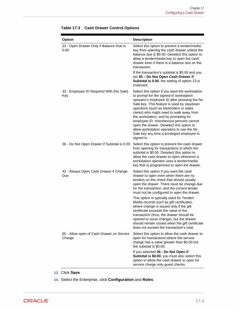
Table 17-3 Cash Drawer Control Options
Option Description
23 - Open Drawer Only if Balance Due is0.00
Select this option to prevent a tender/mediakey from opening the cash drawer unless thebalance due is $0.00. Deselect this option toallow a tender/media key to open the cashdrawer even if there is a balance due on thetransaction.
If the transaction’s subtotal is $0.00 and youset 36 – Do Not Open Cash Drawer ifSubtotal is 0.00, the setting of option 23 isirrelevant.
33 - Employee ID Required With [No Sale]Key
Select this option if you want the workstationto prompt for the signed-in workstationoperator’s employee ID after pressing the NoSale key. This feature is used by staydownoperators (such as bartenders or salesclerks) who might need to walk away fromthe workstation, and by prompting foremployee ID, mischievous persons cannotopen the drawer. Deselect this option toallow workstation operators to use the NoSale key any time a privileged employee issigned in.
36 - Do Not Open Drawer if Subtotal is 0.00 Select this option to prevent the cash drawerfrom opening for transactions in which thesubtotal is $0.00. Deselect this option toallow the cash drawer to open whenever aworkstation operator uses a tender/mediakey that is programmed to open the drawer.
42 - Always Open Cash Drawer if ChangeDue
Select this option if you want the cashdrawer to open even when there are notenders on the check that should usuallyopen the drawer. There must be change duefor the transaction, and the current tendermust not be configured to open the drawer.
This option is typically used for Tender/Media records such as gift certificates,where change is issued only if the giftcertificate exceeds the value of thetransaction (thus, the drawer should beopened to issue change), but the drawershould remain closed when the gift certificatedoes not exceed the transaction’s total.
65 - Allow open of Cash Drawer on ServiceCharge
Select this option to allow the cash drawer toopen for transactions where the servicecharge has a value greater than $0.00 butthe subtotal is $0.00.
If you selected 36 - Do Not Open ifSubtotal is $0.00, you must also select thisoption to allow the cash drawer to open forservice charge only guest checks.
13. Click Save.
14. Select the Enterprise, click Configuration and Roles.
Chapter 17Configuring a Cash Drawer
17-4

15. Select the role type, click Operations and Miscellaneous.
16. Select the appropriate options for cash drawer privileges.
Table 17-4 Cash Drawer Privilege Options
Option Description
17 - Authorize/Perform unassignment ofcash drawer from others
Select this option if you want employees inthe employee class to use the UnassignCash Drawer key to unassign cash drawersfrom other workstation operators.
You should not select this option for everyemployee, but you should typically set it onlyfor management employee classes.
Setting this option allows workstationoperators in the employee class to usefunction keys 839 - Assign Cash Drawer 1and 840 - Assign Cash Drawer 2.
34 - Authorize Open Cash Drawer Using the[No Sale] Key
Select this option to allow employeesassociated with the role to open the cashdrawer outside of a transaction using the NoSale key, and to authorize non-privilegedemployees to do so.
88 - Authorize Cash Drawer Reconnection Select this option to allow employeesassociated with the role to authorize a cashdrawer cable reconnection on a workstation.
17. Click Save.
Related Topics
• Assigning and Unassigning a Cash Drawer
Coin DispenserA coin dispenser (sometimes called a coin changer) is a device attached to aworkstation that holds coins. A coin dispenser is not assigned to a workstation orserver. When connected to a workstation and configured, a cash tender sendscommands to the coin dispenser to dispense coins. The coin dispenser controls onlythe coin portion of a cash transaction. If the customer presents $20.00 to pay a $16.45guest check, the coin dispenser automatically dispenses $0.55, but the workstationoperator must give the remaining $3.00 to the customer.
The coin dispenser hardware varies the coins that are dispensed to avoid depleting asingle type of coin. For example, if the device dispenses $0.55 three times in a row, itis probable that both of the following combinations dispense at least once:
• 1 Quarter and 3 Dimes
• 2 Quarters and 1 Nickel
Related Topics
• Configuring a Coin Dispenser
Chapter 17Coin Dispenser
17-5
Configuring a Coin Dispenser1. In the EMC, select the property, click Setup and Workstations.
2. Double-click the workstation to open it in form view.
3. Click the Devices tab.
4. In the Peripheral Device Configuration section, click Add.
5. In the Select Peripheral Device Type drop-down list, select Coin Dispenser.
6. Enter the COM Port, and click OK.
7. Click Save.
8. On the workstation, allow the configuration change to download to the client.
9. Connect the coin dispenser’s serial cable to the appropriate COM port.
10. Restart the workstation.
11. If the workstation is a Win32 client, modify the device settings for the COM port tomatch the COM Port you set in Step 6.
Ensure that a workstation with a coin dispenser attached does not have a printeror other device configured for the same COM port as the coin dispenser. Havinganother device connected but not in use can cause problems with coin dispenseroperations.
12. Restart the workstation.
13. Verify that the coin dispenser is connected and ready for operation:
a. Sign in to the workstation as an employee with PMC privileges.
b. Launch PMC and click the Functions tab.
c. Click Device Diagnostics.
d. Click Dispense Change. The coin dispenser should dispense a penny.
Related Topics
• Coin Dispenser
Magnetic Stripe ReaderWorkstation operators scan magnetic stripe cards using a magnetic stripe reader(MSR) attached to a workstation. Magnetic cards are commonly used as:
• Credit Cards
• Gift Cards
• Employee Identification Cards
Related Topics
• Configuring a Magnetic Stripe Reader
Chapter 17Configuring a Coin Dispenser
17-6

Installing the MSR Sleeve for Oracle MICROS Tablet E-Series 8-Inch and 11-Inch Devices
The magnetic stripe reader (MSR) sleeve for Oracle MICROS Tablet E-Series 8-inchand 11-inch devices supports Transaction Vault Second Generation (TV2G) and dataencryption.
Before installing the magnetic stripe reader (MSR) sleeve driver for Oracle MICROSTablet E-Series devices, ensure that the device has the following prerequisiterequirements:
• Microsoft Windows 8.1 operating system
• Microsoft .NET Framework 4.0 or later
Contact Oracle Support to obtain the VeriFone E23x card reader driver before youbegin the following steps.
1. If a previous version of the driver exists, uninstall the old driver components beforeinstalling the new driver.
a. Open Control Panel and click Programs and Features.
b. Uninstall the following program components:
• E23x Driver Installer versions
• E23x OPOS DLL
• Microsoft POS for .NET 1.12
• OPOS Common Control Objects 1.13.001
2. Run the E23xDriverInstaller_1.2.0.exe file, and click Yes each time you areprompted.
3. Run the E23x_OPOS_DLL_Install_1.5.2.0.exe file, and click Yes each time youare prompted.
The driver and OPOS DLL installation configures a default OPOS device name forthe magnetic stripe reader (MSR). Configure Simphony to use the exact name touse the MSR.
Related Topics
• Configuring a Magnetic Stripe Reader
• Testing the MSR Sleeve for Oracle MICROS Tablet E-Series 8-Inch and 11-InchDevices
Configuring a Magnetic Stripe Reader1. In the EMC, select the property, click Setup and Workstations.
2. Double-click the workstation to be used with the magnetic stripe reader (MSR).
3. Click the Options tab and the Display/Security sub-tab.
4. Select the appropriate MSR options.
Chapter 17Installing the MSR Sleeve for Oracle MICROS Tablet E-Series 8-Inch and 11-Inch Devices
17-7
Table 17-5 MSR Workstation Options
Option Description
12 - Mag Card Entry Required for EmployeeID
Select this option if you want all employee IDentries at the workstation to be made byswiping a magnetic employee ID card. Theworkstation does not accept an employee IDnumber entered through the keyboard ortouchscreen.
50 - Mag Card or Fingerprint Scan Requiredfor Employee ID
Select this option if you want all employee IDentries at the workstation to be made using afingerprint scan or by swiping a magneticcard. That is, employees must swipe a cardor scan a fingerprint.
51 - Mag Card and Fingerprint ScanRequired for Employee ID
Select this option if you want all employee IDentries at the workstation to be made using afingerprint scan and by swiping a magneticcard. That is, employees must both swipe acard and scan a fingerprint.
5. If you are using an encrypted MSR (for example, the MSR sleeve for OracleMICROS Tablet E-Series 8-inch and 11-inch devices with Transaction VaultSecond Generation (TV2G)), complete the following steps:
a. Click the Hardware/Cash Drawer sub-tab.
b. Select 55 - Enable Encrypted Magnetic Stripe Reader Support.
After you select this option, you cannot turn it off. Before setting this option,ensure that the credit card processor or gateway supports encryptionfunctionality.
6. Click the Devices tab.
7. Click Add and select a magnetic stripe reader from the Select Peripheral DeviceType drop-down list.
8. Select the COM Port Settings (if necessary) and click OK.
9. Click Save.
Related Topics
• Magnetic Stripe Reader
• Testing the MSR Sleeve for Oracle MICROS Tablet E-Series 8 and 11 InchDevices
Testing the MSR Sleeve for Oracle MICROS Tablet E-Series 8-Inch and 11-Inch Devices
You can test the magnetic stripe reader (MSR) swiper functionality after you install thedriver and configure the MSR.
1. Copy the e23xservice.exe and e23xD.dll files to the [Drive]:\Program Files\Verifone\E23xOPOS folder.
2. Close the ServiceHost application.
Chapter 17Testing the MSR Sleeve for Oracle MICROS Tablet E-Series 8-Inch and 11-Inch Devices
17-8

3. Run e23xservice.exe.
4. In the OPOS MSR section of the dialog box, select the following options:
• Open
• Claim
• Enable
• D. Ev (Data Events)
After each successful swipe attempt, the D. Ev option is deselected.
5. Swipe the magnetic card. If the card swipe was successful, a message appearswith the card data.
Related Topics
• Installing the MSR Sleeve for Oracle MICROS Tablet E-Series 8-Inch and 11-InchDevices
• Configuring a Magnetic Stripe Reader
Barcode Reader Setup MethodsA barcode is an optical machine-readable representation of data. Barcodes are usedto quickly order items. Workstation operators scan barcodes using barcode scannersattached to workstations. When a barcode is scanned, the workstation softwareprocesses the data and matches it with a menu item programmed in the Simphonydatabase.
The following two methods allow you to configure barcode menu item ordering:
• Use the Barcodes module in the Enterprise Management Console (EMC)
• Use the number lookup (NLU) method
The following table outlines the differences between the two methods:
Table 17-6 Barcode Reader Setup Methods
Barcodes Module Method NLU Method
Greater configuration flexibility Less flexible configuration
More complex configuration Simplified configuration
Associate many different barcodes with thesame menu item (for example, pricing chewinggum items the same)
Not supported
Associate two different prices of one definitionwith different barcodes (for example, small orlarge coffee)
Not supported
Allows up to 14-digit barcode Allows up to 12-digit barcode
Related Topics
• Configuring a Barcode Reader Using the Barcodes Module Method
• Configuring a Barcode Reader Using the Number Lookup (NLU) Method
Chapter 17Barcode Reader Setup Methods
17-9

Configuring a Barcode Reader Using the Barcodes ModuleMethod
1. In the EMC, select the Enterprise, property, or revenue center click Configurationand Barcodes.
2. Insert a barcode record.
3. In the Barcode column, enter the numeric value that the barcode represents.
4. Click the ellipsis point (...) symbol in the Master column, select the master menuitem to be ordered when the barcode is entered, and click OK.
5. In the Definition column, select the Menu Item Definition (belonging to theselected Menu Item Master) to be ordered when the barcode is entered. If youselect 0 - All Definitions, the workstation determines which definition to order atthe time the barcode is entered, based on active Menu Levels and other criteria.
This column is only active when you set the Menu Item Master column to a valueother than 0 - None.
6. In the Price # column, select the Menu Item Price (belonging to the selected MenuItem Definition) to be ordered when the barcode is entered. If you select 0 - AllPrices, the workstation determines which price to order at the time the barcode isentered, based on active Menu Levels and other criteria.
This column is only active when you set the Menu Item Definition column to avalue other than 0 - All Definitions.
7. In the Alternate Price column, enter the price to charge for the item when thebarcode is entered.
This value is used only when you set a value greater than 0.00; if the value is 0.00,the price from the Menu Item Price record is used.
8. In the Alternate Prep Cost column, enter the prep cost to use for the item when itis ordered by the barcode.
This value is used only when you set a value greater than 0.00; if the value is 0.00,the prep cost from the Menu Item Price record is used.
9. Click Save.
10. Select the Enterprise or property, click Setup and Barcode Format Sets.
11. Insert a barcode format set record, and then double-click it.
12. Click Add.
13. In the Input Length field, enter the number of digits in the scanned barcodes.
14. In the Returned Start field, enter the first digit to use in the numeric value toreturn.
15. In the Returned Length field, enter the number of digits to read as the numericvalue to return.
16. Click Save.
17. Select the property, click Setup and Workstations.
18. Double-click the workstation to be used with the barcode reader.
Chapter 17Configuring a Barcode Reader Using the Barcodes Module Method
17-10
19. Click the Transactions tab.
20. Select the Barcode Format Set for the workstation to use.
The Barcode Format Set determines how the workstation reads barcodes ofvarious lengths.
21. Click the Devices tab.
22. Click Add and select the barcode reader from the Select Peripheral Device Typedrop-down list.
23. Select the COM Port Settings (if necessary) and click OK.
24. Click Save.
25. Select the revenue center, click Setup and RVC Parameters.
26. From the Barcode Menu Item NLU Group # drop-down list, select the numberlookup (NLU) that is reserved for barcodes.
When you select a value other than 0 - None, workstation operators can order anyMenu Item Definition associated with the Barcode Group by scanning or manuallyentering a barcode. For example, if you set this field to 3 - Barcode, the menuitem NLU Group 3 function key can be added to a touchscreen, and theworkstation operator can manually enter a barcode and press the key to order theitem.
27. Click Save.
Related Topics
• Barcode Reader Setup Methods
Configuring a Barcode Reader Using the Number Lookup(NLU) Method
1. In the EMC, select the Enterprise, property, revenue center, or zone, clickDescriptors and NLU Names.
2. Enter the name of the NLU descriptor (for example, Barcode Items) in the Textfield.
3. Click Save.
4. Select the revenue center, click Setup and RVC Parameters.
5. From the Barcode Menu Item NLU Group # drop-down list, select the numberlookup (NLU) that you created in Step 2.
6. Click the Options tab.
7. If you want to perform a check digit verification (CDV) on every NLU entry, select33 - Enable UPC Algorithm for Barcode NLU Entries.
8. If you want barcodes entered in 8-digit UPC-E format to be expanded to 12-digitUPC-A format, select 34 - Convert UPC-E to UPC-A. If you selected option 33 inStep 7, select option 34 as well.
9. Click Save.
10. Select the Enterprise, property, revenue center, or zone, click Configuration andMenu Item Maintenance.
Chapter 17Configuring a Barcode Reader Using the Number Lookup (NLU) Method
17-11

11. Search for and select a menu item definition record for a menu item that can beordered by barcode.
12. Select the NLU Group from the drop-down list. This is the same NLU that youcreated in Step 2.
13. Enter the barcode value for the menu item in the NLU Numberfield.
14. Click Save.
Related Topics
• Barcode Reader Setup Methods
Fingerprint ScanningThis section describes fingerprint scanning. Fingerprint scanning provides greatersecurity by verifying an employee’s identify. You can use an external USB fingerprintreader with the following devices to scan fingerprints:
• Oracle MICROS Tablet E-Series
• Oracle MICROS Workstation 6
• Oracle MICROS Workstation 5a
• Oracle MICROS PC Workstation 2015
• A PC running a Simphony version 2.x client that is attached to the PC with a USBconnection
You can require employees to scan fingerprints when performing the followingoperations:
• Signing in to a workstation
• Clocking in and out
• Authorizing privileged operations
Privileged employees can perform the following actions:
• Enroll themselves and other employees’ fingerprints in Simphony
• Register up to ten different fingers (in the event that employee digits becomeincapacitated (cut, removed, or bandaged)
Auditors can determine whether an employee performed an authorization using afingerprint reader, manual entry, or magnetic card swipe.
Related Topics
• Configuring the Biometrics CAL Package Deployment
• Configuring Employee Privileges for the Fingerprint Reader
• Setting the Front of House to Assign Employee Personal Identification Number(PIN)
• Configuring the Workstation Employee Fingerprint Sign In Options
• Scanning a Fingerprint
Chapter 17Fingerprint Scanning
17-12
Configuring the Biometrics CAL Package Deployment1. In the EMC, select the Enterprise level, click Setup and CAL Packages.
2. Select Biometrics in the navigation tree.
3. Click the Deployment Schedules tab.
4. Click Add Deployment.
5. Select 1 - Property/Enterprise in the Deployment Type drop-down list.
6. Select 0 - Enterprise in the Property field.
7. Select 0 - Install in the Action to Take drop-down list.
8. Click Save.
Related Topics
• Fingerprint Scanning
Configuring Employee Privileges for the Fingerprint Reader1. In the EMC, select the Enterprise level, click Configuration and Roles.
2. Select the role type, click the Operations tab, and the PMC General/Reports sub-tab.
3. Select 30001 - Run PMC to allow employees associated with the role to open theProperty Management Console (PMC) using function key 300.
4. Click the PMC Procedures sub-tab.
5. Select 30055 - Assign Employee Fingerprint Scan and 30052 - AssignEmployee PIN.
6. Click Save.
Related Topics
• Fingerprint Scanning
Setting the Front of House to Assign Employee PersonalIdentification Number (PIN)
1. In the EMC, select the Enterprise, property, revenue center, or zone, clickConfiguration, and Page Design.
2. Open the Front of House Home or Sign In page.
3. On the Edit tab, click Button.
4. On the General sub-tab, enter Assign PIN in the Legend field.
5. Select Function from the Type drop-down.
6. Click the black arrow directly beneath the Type drop-down and select AssignEmployee PIN.
7. Position and size the button on the page. Use the Style arrow to change the color.
Chapter 17Configuring the Biometrics CAL Package Deployment
17-13

8. Click Save.
Related Topics
• Fingerprint Scanning
Configuring the Workstation Employee Fingerprint Sign InOptions
1. In the EMC, select the property, click Setup and Workstations.
2. Double-click the workstation to use with a fingerprint reader.
3. Click the Options tab.
4. Select the appropriate security options as described in the following table.
Table 17-7 Employee Security Options
Option Selecting This Option Requires That AllEmployees …
47 - Fingerprint Scan Required forEmployee ID
Scan a fingerprint.
48 - Employee ID or Fingerprint ScanRequired for Employee ID
Scan a fingerprint or enter the employee IDnumber.
49 - Employee ID and Fingerprint ScanRequired for Employee ID
Scan a fingerprint and enter the employeeID number.
50 - Mag Card or Fingerprint Scan Requiredfor Employee ID
Scan a fingerprint or swipe an employee IDcard.
51 - Mag Card and Fingerprint ScanRequired for Employee ID
Scan a fingerprint and swipe an employeeID card.
5. Click Save.
Related Topics
• Fingerprint Scanning
Scanning a FingerprintYou can scan a fingerprint using a workstation or the Simphony EnterpriseManagement Console (EMC).
1. If you want to scan a fingerprint using a workstation:
a. Sign in to the workstation as an employee with the proper role privileges.
b. Open the Edit Employee PIN function.
c. Select the employee whose fingerprints need to be scanned.
d. Click the Enroll Fingerprint button.
e. Follow the prompts to enroll up to three fingers for one employee.
f. Click Yes at the prompt to scan the same finger three times, or click No toscan different fingers.
Chapter 17Configuring the Workstation Employee Fingerprint Sign In Options
17-14

g. Place the finger to scan on the fingerprint reader, and then remove it when thescan is complete. The scanner flashes red while scanning and turns blue afterthe scan is complete. Repeat this step for each finger.
2. If you want to scan a fingerprint using the Simphony Enterprise ManagementConsole (EMC):
a. Select the Enterprise, property, or revenue center, click Configuration, andEmployee Maintenance.
b. Search for and select the employee record.
c. On the General sub-tab, click the Fingerprint Enrollment button.
d. Follow the prompts to enroll one or more fingerprints.
Related Topics
• Fingerprint Scanning
Configuring a ScaleA scale connects to the workstation and is used for menu items that are priced byweight (for example, salad bar). You can configure Simphony to calculate weight inounces, pounds, or kilograms.
1. In the EMC, select the property, click Setup and Workstations.
2. Double-click the workstation to open it in form view.
3. Click the Devices tab.
4. In the Peripheral Device Configuration section, click Add.
5. In the Select Peripheral Device Type drop-down list, select Scale (Serial).
6. Enter the COM Port to which the scale connects.
7. Select the following settings, and click OK:
• Baud Rate: 9600
• Parity: E
• Data Bits: 7
• Stop Bits: 1
8. Click the Options tab and the Hardware/Cash Drawer sub tab.
9. Select 13 - Enable Scale Interface to allow communication between theworkstation and scale.
10. (Optional) If you are using an Oracle MICROS Tablet E-Series, click the Display/Security sub tab and deselect 39 - Floating tablet.
11. Click Save.
12. On the workstation, allow the configuration change to download to the client.
13. Connect the scale’s serial cable to the workstation’s serial COM port.
14. Connect the scale’s power cord to the outlet.
15. Restart the workstation.
16. Verify that the scale is connected and ready for operation:
Chapter 17Configuring a Scale
17-15

a. Sign in to the workstation as an employee with PMC privileges.
b. Launch PMC and click the Functions tab.
c. Click Device Diagnostics.
d. Click Get Scale Weight.
e. Place a weighed menu item on the scale and add the menu item to a guestcheck.
Related Topics
• Understanding Tare Weight
• Configuring a Weighed Menu Item
• Setting the Tare Weight for a Menu Item
Chapter 17Configuring a Scale
17-16
18Reporting
Simphony provides reports at the Enterprise and property levels. You can assignprivileges to allow employees to run reports.
• Allowing Employees to Run Reports
• List of PMC Reports
• Configuring Employee Privileges for Oracle Hospitality Reporting and Analytics
• Configuring the Log Files for Oracle Hospitality Reporting and Analytics
Related Topics
• Allowing Employees to Run Reports
• Configuring Employee Privileges for Oracle Hospitality Reporting and Analytics
• Configuring the Log Files for Oracle Hospitality Reporting and Analytics
• List of PMC Reports
Allowing Employees to Run Reports1. In the EMC, select the Enterprise level, click Configuration and Roles.
2. Select the role type, click the Operations tab, and the PMC General/Reports sub-tab.
3. Select 30001 - Run PMC to allow employees associated with the role to launchthe Property Management Console (PMC) on the workstation using Function Key300, Launch PMC.
4. Select 10022 - Run PMC Reports in Another Revenue Center to allowemployees associated with the role to run PMC Autosequences (Reports) forrevenue centers other than the revenue center to which they are assigned.
5. Click the Ad Hoc Reports tab.
6. In the Report Options section, select the reports you want employees to run.
7. Click Save.
Related Topics
• Reporting
• List of PMC Reports
List of PMC ReportsOnline PMC Reports
Authorized employees can run the following Property Management Console (PMC)reports when the workstation is in online mode:
18-1
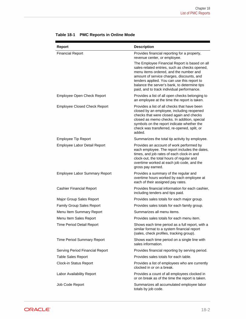
Table 18-1 PMC Reports in Online Mode
Report Description
Financial Report Provides financial reporting for a property,revenue center, or employee.
The Employee Financial Report is based on allsales-related entries, such as checks opened,menu items ordered, and the number andamount of service charges, discounts, andtenders applied. You can use this report tobalance the server’s bank, to determine tipspaid, and to track individual performance.
Employee Open Check Report Provides a list of all open checks belonging toan employee at the time the report is taken.
Employee Closed Check Report Provides a list of all checks that have beenclosed by an employee, including reopenedchecks that were closed again and checksclosed as memo checks. In addition, specialsymbols on the report indicate whether thecheck was transferred, re-opened, split, oradded.
Employee Tip Report Summarizes the total tip activity by employee.
Employee Labor Detail Report Provides an account of work performed byeach employee. The report includes the dates,times, and job rates of each clock-in andclock-out, the total hours of regular andovertime worked at each job code, and thegross pay earned.
Employee Labor Summary Report Provides a summary of the regular andovertime hours worked by each employee ateach of their assigned pay rates.
Cashier Financial Report Provides financial information for each cashier,including tenders and tips paid.
Major Group Sales Report Provides sales totals for each major group.
Family Group Sales Report Provides sales totals for each family group.
Menu Item Summary Report Summarizes all menu items.
Menu Item Sales Report Provides sales totals for each menu item.
Time Period Detail Report Shows each time period as a full report, with asimilar format to a system financial report(sales, check profiles, tracking group).
Time Period Summary Report Shows each time period on a single line withsales information.
Serving Period Financial Report Provides financial reporting by serving period.
Table Sales Report Provides sales totals for each table.
Clock-in Status Report Provides a list of employees who are currentlyclocked in or on a break.
Labor Availability Report Provides a count of all employees clocked inor on break as of the time the report is taken.
Job Code Report Summarizes all accumulated employee labortotals by job code.
Chapter 18List of PMC Reports
18-2
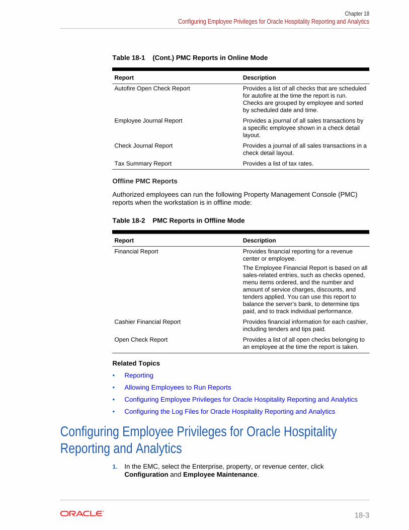
Table 18-1 (Cont.) PMC Reports in Online Mode
Report Description
Autofire Open Check Report Provides a list of all checks that are scheduledfor autofire at the time the report is run.Checks are grouped by employee and sortedby scheduled date and time.
Employee Journal Report Provides a journal of all sales transactions bya specific employee shown in a check detaillayout.
Check Journal Report Provides a journal of all sales transactions in acheck detail layout.
Tax Summary Report Provides a list of tax rates.
Offline PMC Reports
Authorized employees can run the following Property Management Console (PMC)reports when the workstation is in offline mode:
Table 18-2 PMC Reports in Offline Mode
Report Description
Financial Report Provides financial reporting for a revenuecenter or employee.
The Employee Financial Report is based on allsales-related entries, such as checks opened,menu items ordered, and the number andamount of service charges, discounts, andtenders applied. You can use this report tobalance the server’s bank, to determine tipspaid, and to track individual performance.
Cashier Financial Report Provides financial information for each cashier,including tenders and tips paid.
Open Check Report Provides a list of all open checks belonging toan employee at the time the report is taken.
Related Topics
• Reporting
• Allowing Employees to Run Reports
• Configuring Employee Privileges for Oracle Hospitality Reporting and Analytics
• Configuring the Log Files for Oracle Hospitality Reporting and Analytics
Configuring Employee Privileges for Oracle HospitalityReporting and Analytics
1. In the EMC, select the Enterprise, property, or revenue center, clickConfiguration and Employee Maintenance.
Chapter 18Configuring Employee Privileges for Oracle Hospitality Reporting and Analytics
18-3

2. Search for the employee record.
3. Click the Employee Records tab near the lower part of the screen, and thendouble-click the object number of the appropriate record.
4. Click the Reporting tab to configure an employee’s settings as they pertain tologging in to Reporting and Analytics.
5. If you want to grant the employee an active account in the Reporting and Analyticsdatabase, select Active.
6. To make the employee a default user for all Reporting and Analytics employeerecords associated with the same role, select Default User. This allows newemployees in Reporting and Analytics who share the same role to use the samesettings as this employee.
7. From the Role drop-down, select Workstation Report.
8. Click Save.
The mymicros.net System Administrator and User Guide, located at http://docs.oracle.com/en/industries/hospitality/, contains information about enabling reportsin Oracle Hospitality Reporting and Analytics.
Related Topics
• Reporting
• List of PMC Reports
Configuring the Log Files for Oracle Hospitality Reportingand Analytics
1. In the EMC, select the Enterprise level, click Setup and Enterprise Parameters.
2. Click the mymicros.net tab and enter the appropriate information. The followingtable describes the fields.
Table 18-3 Reporting and Analytics Settings
Field Description
Logs to Keep Enter the number of Data Transfer Service(DTS) logs to retain.
Error Files to Keep (days Enter the number of days the applicationretains error file logs.
Verbosity Select the Verbosity level for DTS logging.You should typically set this value toNormal. Set verbose logging to Extendedor Super for troubleshooting as theseelevated levels create large log files andslow performance.
mymicros.net Machine Name Enter the name of the Reporting andAnalytics server computer using the formathttp://YourMyMicrosUrl.
Chapter 18Configuring the Log Files for Oracle Hospitality Reporting and Analytics
18-4
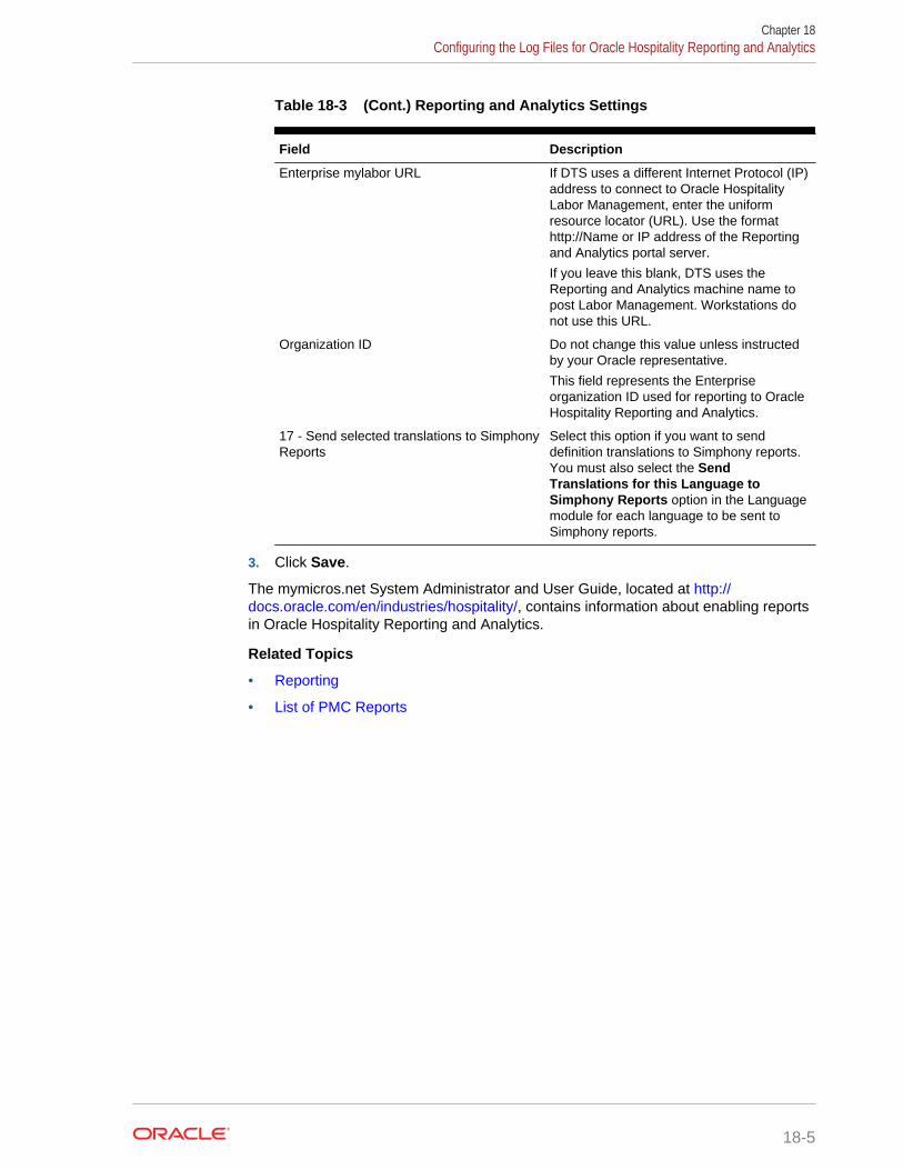
Table 18-3 (Cont.) Reporting and Analytics Settings
Field Description
Enterprise mylabor URL If DTS uses a different Internet Protocol (IP)address to connect to Oracle HospitalityLabor Management, enter the uniformresource locator (URL). Use the formathttp://Name or IP address of the Reportingand Analytics portal server.
If you leave this blank, DTS uses theReporting and Analytics machine name topost Labor Management. Workstations donot use this URL.
Organization ID Do not change this value unless instructedby your Oracle representative.
This field represents the Enterpriseorganization ID used for reporting to OracleHospitality Reporting and Analytics.
17 - Send selected translations to SimphonyReports
Select this option if you want to senddefinition translations to Simphony reports.You must also select the SendTranslations for this Language toSimphony Reports option in the Languagemodule for each language to be sent toSimphony reports.
3. Click Save.
The mymicros.net System Administrator and User Guide, located at http://docs.oracle.com/en/industries/hospitality/, contains information about enabling reportsin Oracle Hospitality Reporting and Analytics.
Related Topics
• Reporting
• List of PMC Reports
Chapter 18Configuring the Log Files for Oracle Hospitality Reporting and Analytics
18-5
19Auditing
Simphony allows you to examine and evaluate various application activities at theEnterprise and property levels.
• Understanding the Audit Trail
• Using the Audit Trail
• Understanding Audit This Record
• Using Audit This Record
Understanding the Audit TrailYou can use the Audit Trail module to view changes made to the Simphonyapplication. The Audit Trail records and reports all additions, changes, and deletionsmade through the EMC and through PMC Procedures. In addition, the Audit Trailreports on successful and failed logins to EMC, PMC Report takers, Key Manageractivity, and Audit Trail purges.
Related Topics
• Using the Audit Trail
Using the Audit TrailYou must have the privilege to access the audit trial at the Enterprise or property level.When an Audit Trail report is taken, the activity is logged to the Audit Trail. All AuditTrail Reports taken are logged as an Enterprise level activity.
1. Select the Enterprise or property, click Tasks, and then click Audit Trail.
2. To perform a quick search on the Search tab:
a. Select the timeframe from the All Changes In drop-down list.
b. Click the Run Quick Search button.
When you perform a quick search, the application ignores the values in thestandard search fields.
3. To perform a standard search, enter or select information in the following fields,and then click the Search button.
19-1
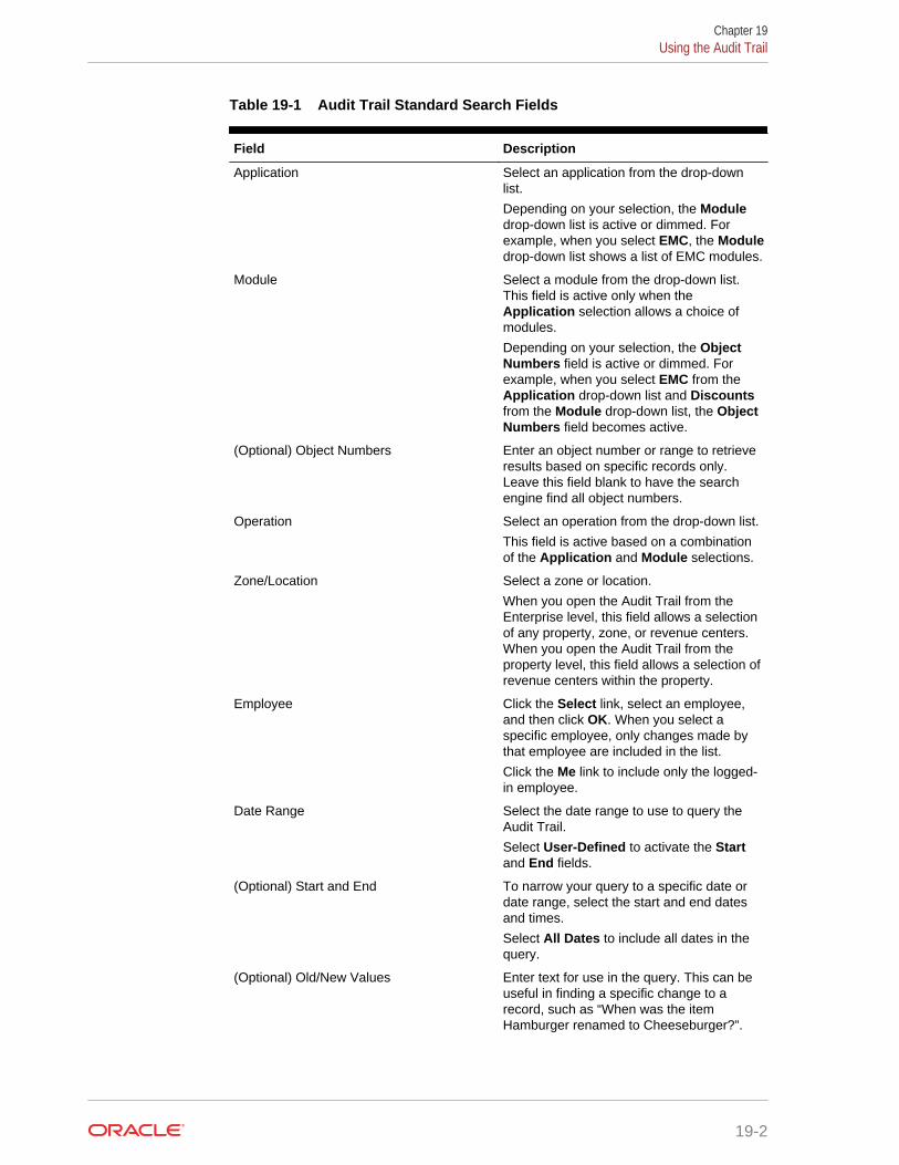
Table 19-1 Audit Trail Standard Search Fields
Field Description
Application Select an application from the drop-downlist.
Depending on your selection, the Moduledrop-down list is active or dimmed. Forexample, when you select EMC, the Moduledrop-down list shows a list of EMC modules.
Module Select a module from the drop-down list.This field is active only when theApplication selection allows a choice ofmodules.
Depending on your selection, the ObjectNumbers field is active or dimmed. Forexample, when you select EMC from theApplication drop-down list and Discountsfrom the Module drop-down list, the ObjectNumbers field becomes active.
(Optional) Object Numbers Enter an object number or range to retrieveresults based on specific records only.Leave this field blank to have the searchengine find all object numbers.
Operation Select an operation from the drop-down list.
This field is active based on a combinationof the Application and Module selections.
Zone/Location Select a zone or location.
When you open the Audit Trail from theEnterprise level, this field allows a selectionof any property, zone, or revenue centers.When you open the Audit Trail from theproperty level, this field allows a selection ofrevenue centers within the property.
Employee Click the Select link, select an employee,and then click OK. When you select aspecific employee, only changes made bythat employee are included in the list.
Click the Me link to include only the logged-in employee.
Date Range Select the date range to use to query theAudit Trail.
Select User-Defined to activate the Startand End fields.
(Optional) Start and End To narrow your query to a specific date ordate range, select the start and end datesand times.
Select All Dates to include all dates in thequery.
(Optional) Old/New Values Enter text for use in the query. This can beuseful in finding a specific change to arecord, such as “When was the itemHamburger renamed to Cheeseburger?”.
Chapter 19Using the Audit Trail
19-2

Table 19-1 (Cont.) Audit Trail Standard Search Fields
Field Description
Preserve Previous Results Select this option to merge the searchresults with the previous search results,instead of overwriting them. Deselect thisoption to see only the results of the mostrecent search.
4. If the number of results that will be returned exceeds the pre-set thresholds forAudit Trail results (for example, 10,000 records or more), the application promptsyou to confirm the action.
5. To view the search results for a quick search or a standard search, click theResults tab.
a. To save the results, click the Save to Disk button, select the directory, andthen click the Save button.
b. To copy the results into another application (such as Notepad or email) withoutstoring the information, click the Formatted Results button, and then click theCopy button.
6. To manually remove old records from the Audit Trail table in the database, clickthe Purge tab.
The Purge tab is visible only at the Enterprise level, and you must have the PurgeAudit Trail privilege.
7. Select the date before which the records will be purged, and then click the Purgebutton. For example, if you select 9/1/2016, the application deletes all records fromSeptember 1, 2016 and earlier.
Records are deleted based on the UTC date of the Audit Trail record.
In addition to this manually initiated purge, the Data Transfer Service (DTS)purges Audit Trail records automatically.
Related Topics
• Understanding the Audit Trail
Understanding Audit This RecordIn almost every module, you can audit an individual record or a group of similarrecords. The results usually show the record or records at a specific position. Forexample, consider the following actions:
1. Add a Tender Media record at Object Number 1234.
2. Change the record’s name to Cash.
3. Delete the record.
4. Add a new record at Object Number 1234.
5. Change the record’s name to MasterCard.
After performing these steps, the Audit This Record results show all five of thechanges (not just the changes for steps 4 and 5). Although the first Tender Mediarecord was deleted, it is considered “this record” for functional purposes. In short, all
Chapter 19Understanding Audit This Record
19-3
records at the same object number are treated as “this record” and are included in theresults.
Related Topics
• Using Audit This Record
Using Audit This Record1. Select the Enterprise or property, and then open a module that contains at least
one record.
2. Highlight one or more records, right-click inside the first column, and then selecteither Audit This Record (single record) or Audit Selected Records (multiplerecords). The Audit Record tab shows the information for the selected records.
Alternatively, from the EMC toolbar, click Edit, and then select Audit ThisRecord.
3. To run specific queries on the selected record or records, click the ShowAdvanced Options link.
4. Use the same search parameters that are available in the Audit Trail module. See Using the Audit Trail for more information.
Related Topics
• Understanding Audit This Record
Chapter 19Using Audit This Record
19-4

20Dining Room Tables and Seating
You can manage the dining room using Simphony with a standard table managementinterface, or using the enhanced Table Management System (available with Simphonyversion 2.6 and later).
• Standard and Enhanced Table Management
• Configuring the Standard Table Management Interface
• Creating Standard Dining Tables
• Table Management
• Reservation List
• Wait List
• Table Management, Reservation, and Wait List Configuration Prerequisites
• Configuring Table Management Privileges
• Configuring Reservation Privileges
• Configuring Wait List Privileges
• Configuring Servers for Table Management
• Configuring Properties for Table Management
• Configuring Custom Images for Table Management
• Configuring KDS or Dining Course Colors and Images for Table Management
• Configuring the Service Total Tender for Table Management
• Enhanced Dining Tables
• Setting Dining Table Classes
• Setting Enhanced Dining Table Attributes
• Configuring Enhanced Dining Tables
• Setting Table Decorator Images
• Configuring Server and Table Availability
• Setting Table Management Options
• Configuring Table Suggestion Factors
• Table Management Alerts
• Configuring Alerts
• Table Management Sections
• Configuring Sections
• Creating the Front of House Reservation List
• Creating the Front of House Wait List
20-1

• Front of House Table Management Tasks
• Host Command Area
• Configuring the Host Command Area
• Dining Table Status
• Configuring the Dining Table Status
• Employee Lines
• Configuring Employee Lines
• Section Layout
• Creating a Section Layout
• Creating Enhanced Dining Tables
• Setting Table Management Functions in Check Detail
• Creating the Employee Section Assignment Report Button
• Configuring Table Cancellation Reasons
• Setting Reservation Timing Parameters
• Setting Wait List Timing Parameters
• Reservation Periods
• Configuring Effectivity
• Configuring Acceptance Limits
• Configuring Occupancy Limits
• Configuring Seating Limits
• Configuring Target Turn Times
• Table Management Configuration Levels
• Reservation Configuration Levels
• Wait List Configuration Levels
Standard and Enhanced Table ManagementDining staff can manage tables in Simphony using one of the following methods:
• Standard table management interface
• Enhanced or integrated tables (available with the Table Management System)
The following table outlines the differences between the two table managementmethods:
Table 20-1 Differences Between Standard and Enhanced Table Management
Function Standard Tables Enhanced Tables
Accept reservations No Yes
Manage a Reservation List No Yes
Manage a Wait List No Yes
Chapter 20Standard and Enhanced Table Management
20-2

Table 20-1 (Cont.) Differences Between Standard and Enhanced TableManagement
Function Standard Tables Enhanced Tables
Provide wait quotes No Yes
Show table status Yes Yes
Estimate table turn times No Yes
Assign tables to sections and employees No Yes
Join and split tables No Yes
Suggest tables No Yes
Use function keys on the workstation forbussing and transferring tables
Yes No
Interface with Oracle HospitalityReservations Management Cloud Service
No Yes
Interface with Oracle Hospitality Gift andLoyalty Advanced Cloud Service
No Yes
Related Topics
• Configuring the Standard Table Management Interface
• Creating Standard Dining Tables
• Setting Dining Table Classes
• Setting Enhanced Dining Table Attributes
• Configuring Enhanced Dining Tables
Configuring the Standard Table Management Interface1. In the EMC, select the Enterprise level, click Setup and Interfaces.
2. Insert a record for Standard Table Management and open it in form view.
3. In the Interface Type drop-down list, select 3 - Table Management.
4. In the Communications Type drop-down list, select 1 - TCP.
5. In the Timeout field, enter the amount of time (in seconds) that Simphony waits fora response from the standard table management interface before showing acommunications failure message.
6. In the Ping Frequency field, enter the amount of time (in seconds) that Simphonypings the standard table management server (for example, every 5 seconds).
7. Click the Options tab and select the appropriate options as described in thefollowing table.
Table 20-2 Standard Table Management Interface Options
Option Description
2 - Enable Interface Log Select this option to have debug informationpost to the Interface log file.
Chapter 20Configuring the Standard Table Management Interface
20-3

Table 20-2 (Cont.) Standard Table Management Interface Options
Option Description
5 - ON = Use 9 digits for Terminal IDs; OFF= Use 2 digits for Terminal IDs
Select this option to transmit the entire 9-digit workstation ID to the standard tablemanagement system.
8 - Enable Offline Posting Select this option to allow offline posting tothe Simphony point of sale (POS).
9 - Determine Link Status Using Ping Select this option if you want the SimphonyPOS to ping the standard tablemanagement system.
10 - ON = Use 5-digit RVC #; OFF = Use 3-digit RVC #
Select this option if you want the standardtable management system posting messageto support a 5-digit revenue center number.(Otherwise, the posting is limited to a 3-digitrevenue center number.)
11 - ON = Use 8-digit Check #; OFF = Use4-digit Check #
Select this option if you want the standardtable management system posting messageto support an 8-digit check number.(Otherwise, the posting is limited to a 4-digitcheck number.)
8. In the TCP Host Name field, enter the name or IP address of the standard tablemanagement server for the interface.
9. In the Port Number field, enter 0 (zero).
10. Click the Properties tab, and select each property that uses the standard tablemanagement system interface.
11. Click the Service Host tab and select the service host that can run the standardtable management system interface.
12. Click Save.
13. Select the revenue center, click Setup and RVC Parameters.
14. Click the Interfaces tab.
15. Select the TMS Operator to whom a check that is opened by the standard tablemanagement system is assigned, before being picked up by a server.
16. Select the TMS User Workstation to which a check that is opened by thestandard table management system is assigned.
17. In the TMS Link drop-down list, select the standard table management interface.
18. Click Save.
Related Topics
• Standard and Enhanced Table Management
• Enhanced Dining Tables
Creating Standard Dining Tables1. In the EMC, select the Enterprise, property, or revenue center, click
Configuration and Page Design.
2. Double-click the Front of House page on which to define standard dining tables.
Chapter 20Creating Standard Dining Tables
20-4

3. On the Edit tab, select the page area on which to place the standard dining tables.
4. Select Other... and Dining Table.
5. Move and adjust the table size on the page. Leave space between tables on thepage layout to ensure visibility of indicators and table state. You can increase thegrid configuration on the page from 24 (default) to 48 using the Change Grid Sizelink.
6. Repeat Steps 4 and 5 to create additional standard dining tables.
7. Click Save.
Related Topics
• Standard and Enhanced Table Management
• Enhanced Dining Tables
Table ManagementYou can integrate dining room management, reservation list, wait list, customerpreferences and seating, and staff availability with the Simphony Table ManagementSystem, Reservation List, and Wait List.
The Simphony Table Management System (TMS) allows you to perform the followingactions:
• Make reservations
• Maintain a Wait List
• Seat guests immediately at available tables
• Control the number of reservations allowed during specific time periods
• See an overview of enhanced dining tables and status
• Update the table status based on coursing
• Manage the seating layout with table, section, and server assignments
• Change table seating capacities
• Estimate wait quote times
Related Topics
• Table Management Configuration Levels
Reservation ListThe Reservation List contains all reservation requests for the revenue center. Hostingstaff with access to the Reservation List can create, edit, and cancel reservationrequests from the list.
Related Topics
• Configuring Reservation Privileges
• Creating the Front of House Reservation List
• Setting Reservation Timing Parameters
• Reservation Configuration Levels
Chapter 20Table Management
20-5

Wait ListOften a guest arrives and asks for a table. When tables are not immediately availablefor seating, the guest may request a wait time and add their name to a Wait List. TheWait List contains all wait requests for the revenue center. The Wait List also showsreservations prior to the scheduled arrival. Reservations appear on the Wait List aconfigured number of minutes prior to the schedule seating time. Hosting staff withaccess to the Wait List can add, change, and abandon wait requests from this list.Hosting staff can manage the Wait List on its own page or as a popup in the host view.
Related Topics
• Configuring Wait List Privileges
• Creating the Front of House Wait List
• Setting Wait List Timing Parameters
• Wait List Configuration Levels
Table Management, Reservation, and Wait ListConfiguration Prerequisites
Before configuring reservations, you must complete the following tasks:
• Configure the Simphony Table Management System (TMS)
• Configure the Simphony Wait List to accept and seat guests with reservations
If the property is using a Wait List, but does not take reservations, you only need toconfigure the TMS before setting up the Wait List. (A Reservation List is not requiredwith the Wait List.)
The Simphony TMS, Reservations, and Wait List integrate with loyalty applicationssuch as Oracle Hospitality Gift and Loyalty, and third party loyalty applications basedon the loadable loyalty modules. When you use Simphony TMS, Reservations, or WaitList with loyalty applications, workstation operators can associate the loyalty accountwith the reservation request or walk-in guest. After associating guest loyaltyinformation with the table request, the information follows the guest through the life ofthe guest check. If you want to use the Simphony TMS, Reservations, or Wait List witha loyalty application, you must configure the loadable loyalty module. LoyaltyConfiguration Tasks contains more information about configuring the loyalty module.
Related Topics
• Table Management Configuration Levels
Related Topics
• Configuring Reservation Privileges
• Creating the Front of House Reservation List
• Setting Reservation Timing Parameters
• Reservation Configuration Levels
Chapter 20Wait List
20-6

Related Topics
• Configuring Wait List Privileges
• Creating the Front of House Wait List
• Setting Wait List Timing Parameters
• Wait List Configuration Levels
Configuring Table Management Privileges1. In the EMC, select the Enterprise, click Configuration and Roles.
2. Select the role type, click the Operations tab and the Guest Management sub-tab.
3. Select the appropriate options for the privileges. The following table summarizesthe privileges associated with table management functionality and therecommended roles to have the privilege set.
Table 20-3 Table Management Privileges
Tab Location Option Number Privilege Name Allows theEmployee to ...
RecommendedRoles
GuestManagement
32020 Edit SectionLayout
Edit a sectionlayout.
Host, Manager
GuestManagement
32021 Activate SectionLayout
Activate adefined sectionlayout as theActive Layout.
Host, Manager
GuestManagement
32022 Delete SectionLayout
Delete anexisting sectionlayout.
Host, Manager
GuestManagement
32031 AssignEmployee toTable
Assign anemployee to atable or sectionin TMS.
Host, Manager
GuestManagement
32032 Mark TableClean or Dirty
Mark a table asclean or dirty.
Host, Manager
GuestManagement
32033 Change TableState
Mark tables asbeing Available,Closed,Reserved, orMerged.
Host, Manager
GuestManagement
32034 SeatUnsuggestedTable
Seat a tablerequest at atable that isdifferent than thetable that wassuggested bythe TMS TableSuggestionSystem.
Host, Manager
Chapter 20Configuring Table Management Privileges
20-7

Table 20-3 (Cont.) Table Management Privileges
Tab Location Option Number Privilege Name Allows theEmployee to ...
RecommendedRoles
GuestManagement
32037 View Legend View the TMSLegend and usethe availablefunctionscontained withinthe form.
Host, Manager
GuestManagement
32038 Allow SeatingGuest Above orBelow TableCapacity
Seat a tablerequest at atable that doesnot support adifferent seatingcapacity (otherthan the covercount on thetable seatingrequest).
Host, Manager
GuestManagement
32039 Allow SeatingGuest at Tablethat does notMeet allRequired TablePreferences
Seat a tablerequest at atable that doesnot meet all ofthe seatingpreferencesdefined on thetable seatingrequest.
Host, Manager
GuestManagement
32040 Edit ServerAvailability
Edit the serveravailability.
Host, Manager
Ad Hoc Reports 31044 Run EmployeeSectionAssignmentReport
Run theEmployeeSectionAssignmentReport.
Host, Manager
Transactions 22 Post Payment toChecksBelonging toAnotherOperator
Unseat a tablerequest.
Host, Manager
Transactions 37 Authorize/Perform Postingof Payment
Unseat a tablerequest.
Host, Manager
Transactions 38 Authorize/Perform Closingof Checks with aZero Balance
Unseat a tablerequest.
Host, Manager
Guest Checks 18 Authorize/Perform Pickupof a CheckBelonging toAnotherOperator
Unseat a tablerequest.
Host, Manager
4. Click Save.
Chapter 20Configuring Table Management Privileges
20-8

Configuring Reservation Privileges1. In the EMC, select the Enterprise, click Configuration and Roles.
2. Select the role type, click Operations and Guest Management.
3. Select the appropriate options for the privileges. The following table summarizesthe privileges associated with reservation functionality and the recommended rolesto have the privilege set:
Table 20-4 Reservation Privileges
Option Number Privilege Name Allow the Employeeto ...
RecommendedRoles
32006 Greet Wait List Entry Greet a reservationrequest if the partyarrives earlier thanthe time in which thereservationautomatically movesto the Wait List.
Host, Manager
32007 Mark as No Show Mark a reservationrequest as a no-showif the guest does notarrive.
Host, Manager
32010 Add ReservationEntry
Create a reservationrequest.
Host, Manager
32011 Edit ReservationEntry
Edit an existingreservation request.
Host, Manager
32012 Cancel ReservationEntry
Cancel a reservationrequest.
Host, Manager
32013 Approve ReservationEntry
Approve areservation that isrequesting a date ortime outside theacceptable orallowable timeframe.
Host, Manager
4. Click Save.
Related Topics
• Reservation List
• Table Management, Reservation, and Wait List Configuration Prerequisites
• Reservation Configuration Levels
Configuring Wait List Privileges1. In the EMC, select the Enterprise, click Configuration and Roles.
2. Select the role type, click the Operations tab and the Guest Management sub-tab.
3. Select the appropriate options for the privileges.
Chapter 20Configuring Reservation Privileges
20-9

The following table summarizes the privileges associated with wait list functionalityand the recommended roles to have the privilege set:
Table 20-5 Wait List Privileges
Option Number Privilege Name Allow the Employeeto ...
RecommendedRoles
32001 Add Wait List Entry Create a new WaitList request.
Host, Manager
32002 Edit Wait List Entry Edit an existing WaitList request.
Host, Manager
32003 Abandon Wait ListEntry
Abandon a Wait Listrequest.
Host, Manager
32004 Seat Wait List Entry Seat a Wait Listrequest.
Host, Manager
32005 Unseat Wait ListEntry
Unseat a Wait Listrequest.
Host, Manager
32006 Greet Wait List Entry Greet a Wait Listrequest.
Host, Manager
32007 Mark as No Show Mark a reservationrequest as a no-showif the guest does notarrive.
Host, Manager
4. Click Save.
Related Topics
• Wait List
• Table Management, Reservation, and Wait List Configuration Prerequisites
• Wait List Configuration Levels
Configuring Servers for Table Management1. In the EMC, select the Enterprise, property, or revenue center, click
Configuration and Employee Maintenance.
2. Search for and select the employee record.
3. In the Check Name field, enter the server’s name as you want it to appear on theworkstation. If you do not enter a Check Name, the workstation shows a blankname.
4. Select the Operator Records sub-tab near the lower area of the screen.
5. In the TMS Color field, select the color to distinguish the server from other serverson the host page, and click OK.
Although you can set a different color for each revenue center within a property,Oracle recommends that you use a single color for the server across the property.If you do not set a TMS Color, the workstation shows white.
6. In the Server Efficiency field, enter 0 (zero) if you want the Simphony TableManagement System (TMS) to ignore the server in the table suggestions.
Chapter 20Configuring Servers for Table Management
20-10

The Table Suggestion System (within TMS) sets the Server Efficiency rating todetermine the next table recommended for seating. This rating is a value between0 (zero) and 100, and represents the number of covers that the server canefficiently service at one time.
7. Click Save.
Configuring Properties for Table Management1. In the EMC, select the property, click Setup and Properties.
2. Highlight the property record.
3. In the Simphony Platform field, select 2 - Extensible Clients and Architecture.
4. Click Save.
Configuring Custom Images for Table ManagementYou can load custom images into the Simphony application to represent table seatingconfiguration and statuses. The Table Management System (TMS) uses both customimages and images packaged with Simphony. All images are transparent .PNG files.
Table images show a graphical representation of the table and chairs. These imagescan be a square or round table surrounded by any number of chairs.
Table decorators show a graphical representation of the table status (for example,dirty, closed, or reserved).
1. In the EMC, select the Enterprise, property, or revenue center, click Setup andContent.
2. Double-click the content name row to view the image set for that name.
3. Select the Import from a file link to import custom images.
4. Browse to the file location, select the image file, and click Open.
5. Repeat Steps 2 through 4 for each table image and table decorator you want toimport.
6. Click Save.
Configuring KDS or Dining Course Colors and Images forTable Management
You can set a color or image to indicate the Kitchen Display System (KDS) or diningcourse that the table is being serviced under.
1. In the EMC, select the Enterprise or property, click Descriptors and KDS/DiningCourse.
2. Insert dining course records if they do not exist.
3. In the Course Color field, select a color for each dining course name.
This color appears as the dining course indicator on the table image in theworkstation. For example, appetizers can be green, entrées can be yellow, anddesserts can be red.
Chapter 20Configuring Properties for Table Management
20-11

4. (Optional) In the Course Image Name field, select a the course decorator imageto represent the dining course (in place of a course color). The image you selectreplaces the default Occupied image on the table. To remove a Course Image thatwas previously set, select 0 - None and click OK.
5. Click Save.
Configuring the Service Total Tender for Table ManagementYou must configure a unique tender media record to process seating and unseating ofguests.
1. In the EMC, select the Enterprise, click Configuration and Tender/Media.
2. Create a tender media record and name it TMS.
3. Double-click the record to open it.
4. Set the Key Type to 2-Service Total.
5. Click Save.
Enhanced Dining TablesComplete the following tasks to set up enhanced dining tables:
• Set Dining Table Classes
• Set Enhanced Dining Table Attributes
• Configure Enhanced Tables
Related Topics
• Configuring the Standard Table Management Interface
• Creating Standard Dining Tables
• Setting Dining Table Classes
• Setting Enhanced Dining Table Attributes
• Configuring Enhanced Dining Tables
Setting Dining Table ClassesYou can group and configure similar tables using the Dining Table Classes module.
1. In the EMC, select the Enterprise, property, or revenue center, click Setup andDining Table Class.
2. Insert a dining table class.
3. Select or enter information for the following fields.
Chapter 20Configuring the Service Total Tender for Table Management
20-12

Table 20-6 Dining Table Class Fields
Field Description
Name Enter the name of the dining table class. The nameidentifies the class (for example, 2 Tops, 4 Tops, and soon).
(Optional) Default BackgroundColor
Select a background color to represent the table. Select adifferent color than the page background so as not toblend similar colors. If you associate a transparent tableimage with the dining table class, the background colorappears with the image. If you select 0–None, theapplication shows the table image and background color ofthe page.
(Optional) Default Text Color Select the text color to represent the table number orname. Select a different color than the page backgroundso as not to blend similar colors. If you select 0–None, theapplication shows the default text color of black.
(Optional) Default Image Select the image to represent the table.
Minimum Covers Enter the lowest number of covers that the dining tableclass can accommodate (for example, a 2–Top canaccommodate a minimum of 1 person).
Maximum Covers Enter the largest number of covers that the dining tableclass can accommodate (for example, a 2–Top canaccommodate a maximum of 2 people).
You can overlap covers to seat a specific cover countwithin one or more dining table classes (for example, 4covers on a 4–Top or 6–Top).
Options If you are using enhanced dining tables within the diningtable class, select 1 – Enhanced Dining Table. If you areusing legacy standard tables, deselect EnhancementDining Table.
4. Click Save.
Related Topics
• Standard and Enhanced Table Management
• Enhanced Dining Tables
Setting Enhanced Dining Table AttributesYou can set characteristics of the table for use in the table suggestion process.
1. In the EMC, select the property, click Setup and TMS Table Attributes.
2. Select or enter information for the following fields.
Chapter 20Setting Enhanced Dining Table Attributes
20-13

Table 20-7 TMS Table Attributes Fields
Field Description
Name Enter the name of the attribute,characteristic, or guest preferenceassociated with a table (for example,Accessible, Window Seats, City View,Ocean View, or Booth).
Code Enter the attribute code associated with aguest preference in the request (forexample, ADA, WIND, CITY, OCN, or BTH).
(Optional) Is Exclusive Select this option if the table attributes mustbe met before being included in tableseating suggestions. For example, theAccessible attribute is exclusive.
3. Click Save.
Related Topics
• Standard and Enhanced Table Management
• Enhanced Dining Tables
Configuring Enhanced Dining TablesDining tables represent the physical location where a party can be seated with a QuickSeating operation or from the Wait List.
1. In the EMC, select the property, click Setup and Tables.
2. Select or enter information for the following fields.
Table 20-8 Tables Fields
Field Description
Table Number (# symbol) Enter a unique table number for all revenuecenters within the property. The TableNumber appears on the workstation andrepresents the internal number used todistinguish one table from another within theproperty.
Name Enter a unique table name for all revenuecenters within the property. The table nameappears on the workstation and representsthe local facing name or number used todifferentiate the table from others. Values inthe Name field can be:• All numeric• All alpha• Alpha and then numeric
Chapter 20Configuring Enhanced Dining Tables
20-14
Table 20-8 (Cont.) Tables Fields
Field Description
Class Select the dining table class. The diningtable class defines the type of table. Allinstances of this table number use the color,image, and cover configurations defined forthe selected dining table class.
Create only tables that are to be used forseating within a revenue center. Creatingnon-seatable tables (such as bar tabs)prevents the table suggestion system fromproperly distributing tables.
Do not delete tables unless you no longerneed them for reports. Oracle Hospitalityrecommends that you assign tables that arenot used to a dining table class named toindicate this status. For example, create adining table class named NOT IN USE andassign unused tables to this class. Tablesassigned to the NOT IN USE class cannotbe used for seating, but remain in theSimphony Table Management System forreporting purposes.
Table Attributes You can associate one or more attributeswith a table. When you set attributes, theapplication matches guest preferences withtables. For example, when a guest preferswindow seats, tables associated with awindow seating attribute move up in thetable suggestion process.
3. Click Save.
Related Topics
• Standard and Enhanced Table Management
• Enhanced Dining Tables
Setting Table Decorator Images1. In the EMC, select the Enterprise, property, or revenue center, click Setup and
TMS Parameters.
2. (Optional) Select the link next to each Dining Table Decoration Image Name toview a list of images (set as custom images).
Dining table images are optional but useful as part of daily table managementoperations. See Configuring Custom Images for Table Management for moreinformation about setting custom images.
3. Select an image to represent each of the following statuses:
Chapter 20Setting Table Decorator Images
20-15
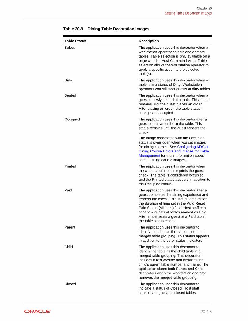
Table 20-9 Dining Table Decoration Images
Table Status Description
Select The application uses this decorator when aworkstation operator selects one or moretables. Table selection is only available on apage with the Host Command Area. Tableselection allows the workstation operator toapply a specific action to the selectedtable(s).
Dirty The application uses this decorator when atable is in a status of Dirty. Workstationoperators can still seat guests at dirty tables.
Seated The application uses this decorator when aguest is newly seated at a table. This statusremains until the guest places an order.After placing an order, the table statuschanges to Occupied.
Occupied The application uses this decorator after aguest places an order at the table. Thisstatus remains until the guest tenders thecheck.
The image associated with the Occupiedstatus is overridden when you set imagesfor dining courses. See Configuring KDS orDining Course Colors and Images for TableManagement for more information aboutsetting dining course images.
Printed The application uses this decorator whenthe workstation operator prints the guestcheck. The table is considered occupied,and the Printed status appears in addition tothe Occupied status.
Paid The application uses this decorator after aguest completes the dining experience andtenders the check. This status remains forthe duration of time set in the Auto ResetPaid Status (Minutes) field. Host staff canseat new guests at tables marked as Paid.After a host seats a guest at a Paid table,the table status resets.
Parent The application uses this decorator toidentify the table as the parent table in amerged table grouping. This status appearsin addition to the other status indicators.
Child The application uses this decorator toidentify the table as the child table in amerged table grouping. This decoratorincludes a text overlay that identifies thechild’s parent table number and name. Theapplication clears both Parent and Childdecorators when the workstation operatorremoves the merged table grouping.
Closed The application uses this decorator toindicate a status of Closed. Host staffcannot seat guests at closed tables.
Chapter 20Setting Table Decorator Images
20-16

Table 20-9 (Cont.) Dining Table Decoration Images
Table Status Description
Reserved The application uses this decorator toindicate a status of Reserved. The TableSuggestion process does not considerreserved tables for seating.
User Suggested The application uses this decorator toidentify the table as the host staffrecommended seating placement for thehighlighted table request on the Wait List.
System Suggested The application uses this decorator toidentify the table as the systemrecommended seating placement for thehighlighted table request on the Wait List.
Highlighted Do not use this decorator.
Host Area This image is not a table decorator, but anoptional image placement for the HostCommand Area. You can use this image toplace the restaurant logo on the host page.
4. Click Save.
Configuring Server and Table Availability1. In the EMC, select the Enterprise, property, or revenue center, click Setup and
TMS Parameters.
2. Click the Configuration tab and the Table Suggestion tab.
3. In the Default Server Available Time (Minutes) field, enter the default number ofminutes to use when making a server unavailable in the Table ManagementSystem (TMS). You can set this to a duration between 1 and 480 minutes.
4. In the Auto Reset Paid Status (Minutes) field, enter the number of minutes thatthe table decorator shows as paid on the host page before returning to anavailable status. You can define a buffer of time between when the table servicemoves from tendered, cleaned, and available for a new seating. Setting a value of0 (zero) or blank defaults the time to 1 minute.
5. Click Save.
Setting Table Management Options1. In the EMC, select the Enterprise, property, or revenue center, click Setup and
TMS Parameters.
2. On the Configuration tab, select Enable Table Management to turn on TableManagement System (TMS) functions in Simphony. Select this option only forproperties and revenue centers that use the TMS features. This option increasesworkstation resources and communications bandwidth for the enterprise.
3. If you are using a loyalty program to look up and process transactions, select theLoyalty Module ID from the drop-down list. If you are not using a loyalty program,select None.
Chapter 20Configuring Server and Table Availability
20-17
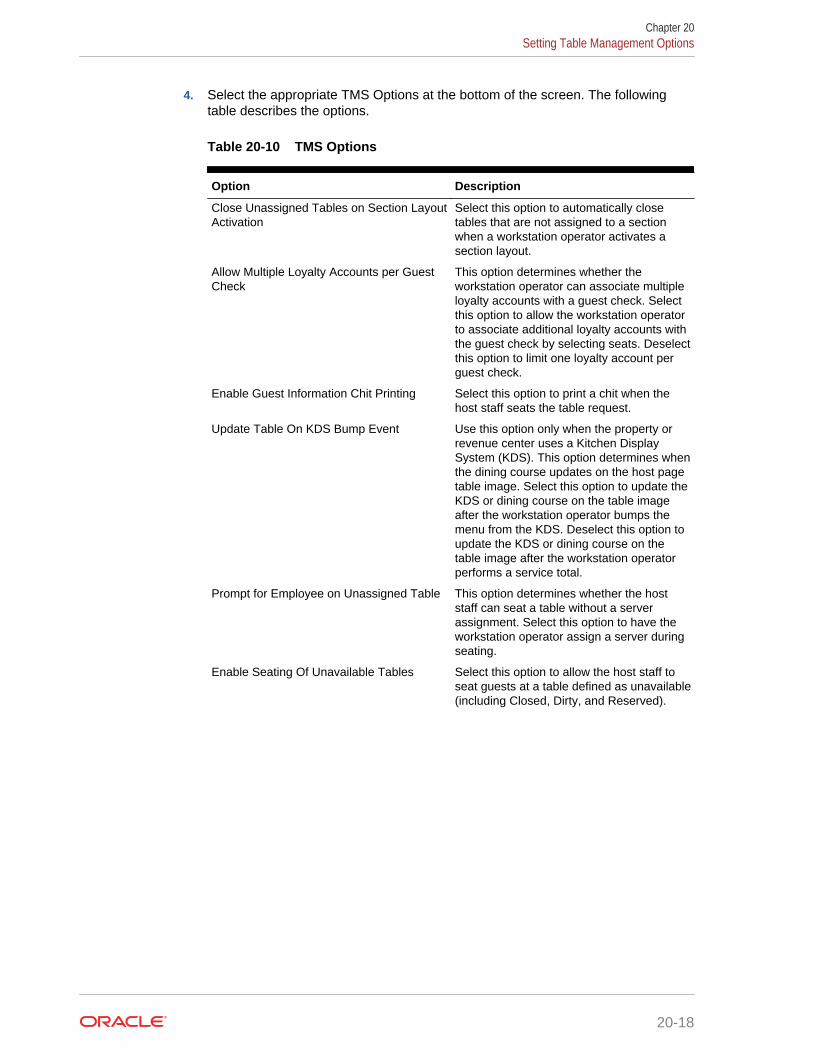
4. Select the appropriate TMS Options at the bottom of the screen. The followingtable describes the options.
Table 20-10 TMS Options
Option Description
Close Unassigned Tables on Section LayoutActivation
Select this option to automatically closetables that are not assigned to a sectionwhen a workstation operator activates asection layout.
Allow Multiple Loyalty Accounts per GuestCheck
This option determines whether theworkstation operator can associate multipleloyalty accounts with a guest check. Selectthis option to allow the workstation operatorto associate additional loyalty accounts withthe guest check by selecting seats. Deselectthis option to limit one loyalty account perguest check.
Enable Guest Information Chit Printing Select this option to print a chit when thehost staff seats the table request.
Update Table On KDS Bump Event Use this option only when the property orrevenue center uses a Kitchen DisplaySystem (KDS). This option determines whenthe dining course updates on the host pagetable image. Select this option to update theKDS or dining course on the table imageafter the workstation operator bumps themenu from the KDS. Deselect this option toupdate the KDS or dining course on thetable image after the workstation operatorperforms a service total.
Prompt for Employee on Unassigned Table This option determines whether the hoststaff can seat a table without a serverassignment. Select this option to have theworkstation operator assign a server duringseating.
Enable Seating Of Unavailable Tables Select this option to allow the host staff toseat guests at a table defined as unavailable(including Closed, Dirty, and Reserved).
Chapter 20Setting Table Management Options
20-18

Table 20-10 (Cont.) TMS Options
Option Description
Ignore Cover Count This option determines the initial guestcount set on the guest check when the hoststaff seats the table request. Select thisoption if you do not want the cover countshown on the guest check; instead theapplication relies on guest checkconfiguration to determine the guest countvalue. Deselect this option to have the covercount set on the table request and providedto the guest check as the initial guest count.
Set this option if you want to maintain a validcover count for the seating record, yetincrement the guest count from 0 (zero) to anumber based on the menu items ordered(entrée count).
When you select Ignore Cover Count, youmust also deselect the option Use Numberof Seats for Guest Count in the RVCParameters module.
Enable Edit Seating Capacity Select this option to allow the workstationoperator to change the seating capacity of atable from its configured number of seats.
Set Seating Capacity on Table Merge Select this option to have the workstationoperator enter the new number of seats fora table when merging tables.
Enable Create and Edit buttons on Wait Listand Reservation List Screens
This option determines whether to show theCreate and Edit buttons on the Wait Listand Reservation List screens. Theworkstation operator can click the buttons inOps (rather than double-tap the ReservationList or Wait List).
Chapter 20Setting Table Management Options
20-19
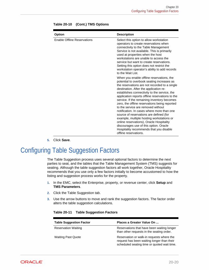
Table 20-10 (Cont.) TMS Options
Option Description
Enable Offline Reservations Select this option to allow workstationoperators to create reservations whenconnectivity to the Table ManagementService is not available. This is primarilyused at properties when the hostworkstations are unable to access theservice but want to create reservations.Setting this option does not restrict theworkstation operator’s ability to add recordsto the Wait List.
When you enable offline reservations, thepotential to overbook seating increases asthe reservations are not recorded to a singledestination. After the application re-establishes connectivity to the service, theapplication reports offline reservations to theservice. If the remaining inventory becomeszero, the offline reservations being reportedto the service are removed withoutnotification. In cases where more than onesource of reservations are defined (forexample, multiple hosting workstations oronline reservations), Oracle Hospitalitydiscourages use of this option. OracleHospitality recommends that you disableoffline reservations.
5. Click Save.
Configuring Table Suggestion FactorsThe Table Suggestion process uses several optional factors to determine the nextparties to seat, and the tables that the Table Management System (TMS) suggests forseating. Although the table suggestion factors all work together, Oracle Hospitalityrecommends that you use only a few factors initially to become accustomed to how thelisting and suggestion process works for the property.
1. In the EMC, select the Enterprise, property, or revenue center, click Setup andTMS Parameters.
2. Click the Table Suggestion tab.
3. Use the arrow buttons to move and rank the suggestion factors. The factor orderalters the table suggestion calculations.
Table 20-11 Table Suggestion Factors
Table Suggestion Factor Places a Greater Value On ...
Reservation Waiting Reservations that have been waiting longerthan other requests in the seating order.
Waiting Past Quote Reservation or walk-in requests where therequest has been waiting longer than theirscheduled seating time or quoted wait time.
Chapter 20Configuring Table Suggestion Factors
20-20

Table 20-11 (Cont.) Table Suggestion Factors
Table Suggestion Factor Places a Greater Value On ...
Reservation Waiting Past Quote Reservation requests where the request hasbeen waiting longer than the scheduledseating time.
Reservation Greeted Reservation requests where the party hasarrived and hosting staff greeted them.
Reservation Reservation requests versus non-reservation requests (walk-ins) in theseating order.
VIP Waiting Reservation requests where the party isdesignated as a VIP and have been waitingversus non-VIP reservation and walk-inrequests that have been waiting in theseating order.
VIP Reservation and walk-in requests where theparty is designated as a VIP in the seatingorder.
Table Dirty Any table marked as Dirty.
Table Paid Any table marked as Paid.
Server Check Count Any server based on their current servicecheck count (open and closed).
Server Cover Count Any server based on their current servicecover count.
Server Efficiency Any server based on their Server EfficiencyRating.
Server Last Assigned Any table based on the table’s currentserver assignment and the time since theserver received a new table seating.
4. Click Save.
Table Management AlertsYou can set two optional types of table management alerts: Service Alerts and CheckAlerts.
Service Alerts show the duration since the last service interaction (for example, guestordered a menu item). If you do not set Service Alerts, the table management systemdoes not track service intervals on the guest check.
Check Alerts show how long the guest has been seated at the table. This alertchanges as the service interaction passes defined thresholds. If you do not set CheckAlerts, the table management system only tracks the duration of time the guest checkis open and does not change the Check Alert color.
Related Topics
• Configuring Alerts
Chapter 20Table Management Alerts
20-21

Configuring Alerts1. In the EMC, select the revenue center, click Setup and Service Alert.
2. Enter the name of the service alert as you want it to appear to the workstationoperator (for example, Recent Service, No Touch Warning, or Service Warning).
3. Set the Service Alert Time to the number of minutes since the last service totalelapses before triggering the service alert. To start the alert immediately uponseating of the guest, set the time to 0 (zero). The application resets the timer to 0when the workstation operator performs a service total with a new menu item onthe guest check.
4. Select the Service Alert Color to distinguish one alert from another in the servicealert table area on the host page. Only seated tables show a service alert color.
5. Click Save.
6. In the EMC, select the revenue center, click Setup and Check Alert.
7. Enter the name of the check alert as you want it to appear to the workstationoperator (for example, In Service, Turn Waiting, or Turn Alert).
8. Set the Check Alert Time to the number of minutes since the check was openedbefore triggering the next check alert. To start the alert immediately upon seatingof the guest, set the time to 0 (zero). The application resets the timer to 0 when theworkstation operator performs a service total with a new menu item on the guestcheck. The check alert remains as the last alert until the workstation operatorcloses the guest check.
9. Select the Check Alert Color to distinguish one alert from another in the checkalert table area on the host page. Only seated tables show a check alert color.
10. Click Save.
Related Topics
• Table Management Alerts
Table Management SectionsYou can group tables within an area or station to indicate assignment to a specificserver. Optional seating section templates allow you to set predefined table layoutswhere the application automatically assigns tables to a specific section. You cancreate seating section layouts at the property level.
Related Topics
• Configuring Sections
Configuring Sections1. In the EMC, select the property, click Setup and Section.
2. Enter the name of the section as you want it to appear to the workstation operatorand in reports.
Chapter 20Configuring Alerts
20-22

3. Select the color used to distinguish one section from another when viewing tableson the host page. Only tables that are assigned to a section inherit the sectioncolor.
4. Click Save.
5. In the EMC, select the property, click Setup and Seating Section Templates.
6. Enter the name of the section template as you want it to appear to the workstationoperator.
7. Select Add to define a table as part of the template.
a. From the new record, click the build box to view a list of tables defined for therevenue center. Alternatively, you can enter the Table ID and press Tab.
b. Select the section from the available list or enter the Section ID.
8. Click Save.
Related Topics
• Table Management Sections
Creating the Front of House Reservation List
The Reservation List allows hosting staff to manage all reservation requests. OracleHospitality recommends that you create a Reservations List on a page for thereservation functions. You can use the template provided in Simphony. If a propertyuses future reservations or multiple dining room layouts, a Tabbed Template providesworkstation operators with a smoother means to navigate between wait lists,reservation lists, and table layouts.
The Table Management System (TMS), Wait List, and Reservation functions mustreside within the same content area on a page in order to interact.
1. In the EMC, select the Enterprise, property, or revenue center, clickConfiguration and Page Design.
2. Double-click the Front of House page on which to place the reservation list.
3. On the Edit tab, select the page area in which to define the reservations.
4. Select Other..., Table Management, and then Reservation Area.
The reservations list contains buttons for creating future reservations. You canplace the reservations list alone or within the Host Command Area, where hostingstaff can hide and recall it. Oracle Hospitality recommends placing thereservations list on its own page. After placing the reservations area, theReservation List settings appear in two sections:
• Reservation List Columns – The columns section allows you to setReservation List columns and formats that appear on the workstation. You canconfigure the content, width, and order in which the columns appear on theReservation List.
• Summary Area – The summary section allows you to set the reservationdetails that appear on the workstation when a workstation operator highlights areservation in the Reservation List.
5. Highlight the reservation area, and select Reservation List Columns.
Chapter 20Creating the Front of House Reservation List
20-23

6. In the Header and Detail Font Size fields, select the size of the font used to showthe reservation heading and detail.
7. For each Reservation List column, select the Enable option if you want the columnname to appear in the workstation Reservation List, and then enter the columnwidth for each column.
Table 20-12 Reservation List Columns
Column Name Description
Cancel Date If a reservation is cancelled or the guestdoes not arrive, this column shows the dateand time of cancellation.
Alert Icon The alert icon is always enabled and is thefirst column shown in the Reservation List.This column contains icons to indicatestatus or properties of the reservationrecord. Alert icons represent the requestmethod, VIP status, and seatingpreferences.
Confirmation Number Simphony issues a confirmation numberafter a workstation operator or guest createsa reservation.
Covers This column shows the number of covers forthe reservation.
Created This column shows the date and time thereservation was created.
Greeted This column shows the time when the hoststaff greeted the guest.
Time The time is always enabled and is thesecond column shown in the ReservationList. This column shows the time when thereservation is scheduled to be seated.
Guest Name This column shows the name in which thereservation was created.
Pager Number Do not use this column.
Phone Number This column shows the guest’s phonenumber.
Request Method This column shows an icon representing thesource of the reservation (phone orInternet).
VIP This column shows an icon representing theVIP flag if the guest has a VIP status.
Wait Quote Do not use this column.
8. Click the black up and down arrows in the top portion of the Reservation ListColumns section to sort and move each enabled column to the order you wantthem to appear in the workstation Reservation List.
9. Select Summary Area.
10. Select Show Summary if you want reservation details to appear in theReservation List when a workstation operator highlights a reservation.
Chapter 20Creating the Front of House Reservation List
20-24
11. In the Summary Height field, enter a static height for the summary information.When you enter 0 (zero), the height of the summary area appears dynamically,depending on the amount of content and details associated with the highlightedreservation.
12. In the Label and Detail Font Size fields, select the size of the font used to showthe summary label and details.
13. For each Reservation summary field:
• Select the Enable option if you want the summary content to appear in theworkstation Reservation List.
• Select the New Line option if you want the summary information to appear ona new line in the workstation Reservation List.
The information in the Summary Area is the same as the Reservation ListColumns, with the addition of the content listed in the following table.
Table 20-13 Reservation List Summary
Summary Content Description
Notes This summary option contains text includedin the Notes field of the reservation record.This field holds up to 255 characters of textand automatically wraps in the summaryarea.
Referral Notes This summary option contains text includedin the Referral Notes field of the reservationrecord. This field holds up to 255 charactersof text and automatically wraps in thesummary area.
14. Click Save.
Related Topics
• Reservation List
• Table Management, Reservation, and Wait List Configuration Prerequisites
• Reservation Configuration Levels
Creating the Front of House Wait List
The Wait List allows hosting staff to manage all table requests (including walk-ins andpending reservations). Oracle Hospitality recommends that you create a Wait List on apage for the table request functions. You can use the templates provided in Simphony.If the property uses future reservations or multiple dining room layouts, a TabbedTemplate provides workstation operators with a smoother means to navigate betweenwait lists, reservation lists, and table layouts.
The Table Management System (TMS), Wait List, and Reservation functions mustreside within the same content area on a page in order to interact.
1. In the EMC, select the Enterprise, property, or revenue center, clickConfiguration and Page Design.
Chapter 20Creating the Front of House Wait List
20-25

2. Double-click the Front of House page on which to place the wait list.
3. On the Edit tab, select the page area in which to define the wait list.
4. Select Other..., Table Management, and Wait List.
The Wait List contains buttons for creating walk-in table requests. You can placethe Wait List alone or within the Host Command Area, where hosting staff can hideand recall it. Oracle Hospitality recommends creating a Wait List on the samepage as the tables to simplify the seating process. After placing the wait list, theWait List settings appear in two sections:
• Wait List Columns – The columns section allows you to set Wait List columnsand formats that appear on the workstation. You can configure the content,width, and order in which the columns appear on the Wait List.
• Summary Area – The summary section allows you to set the wait list detailsthat appear on the workstation when a workstation operator highlights a tablerequest in the Wait List.
5. Highlight the Wait List, and select Wait List Columns.
6. In the Header and Detail fields, select the size of the font used to show the WaitList heading and detail.
7. For each Wait List column, select the Enable option if you want the column nameto appear in the workstation Wait List, and then enter the column width for eachcolumn.
Table 20-14 Wait List Columns
Column Name Description
Abandon Time Do not configure the Wait List to contain thiscolumn.
Alert Icon The alert icon is always enabled and is thefirst column shown in the Wait List. Thiscolumn contains icons to indicate status orproperties of the table request record. Alerticons represent the quote status, requestmethod, VIP status, and seatingpreferences.
Confirmation Number The confirmation number appears only fortable requests that originate from theReservation List.
Covers This column shows the number of covers forthe table request.
Created This column shows the date and time thetable request was created.
Greeted This column shows the time when the hoststaff greeted the guest.
Guest Name This column shows the name for the tablerequest.
Pager Number This column shows the pager number forthe table request.
Phone Number This column shows the guest’s phonenumber.
Chapter 20Creating the Front of House Wait List
20-26
Table 20-14 (Cont.) Wait List Columns
Column Name Description
Request Method This column shows an icon representing thesource of the table request (walk-in, phone-in, or Internet).
VIP This column shows an icon representing theVIP flag if the guest has a VIP status.
Wait Quote This column shows the estimated wait quotetime given for the table request.
8. Click the black up and down arrows in the top portion of the Wait List Columnssection to sort and move each enabled column to the order you want them toappear in the workstation Wait List.
9. Select Summary Area.
10. Select Show Summary if you want table request details to appear in the Wait Listwhen a workstation operator highlights a table request.
11. In the Summary Height field, enter a static height for the summary information.When you enter 0 (zero), the height of the summary area appears dynamically,depending on the amount of content and details associated with the highlightedtable request.
12. In the Label and Detail fields, select the size of the font used to show thesummary label and details.
13. For each Wait List summary field:
• Select the Enable option if you want the summary content to appear in theworkstation Wait List.
• Select the New Line option if you want the summary information to appear ona new line in the workstation Wait List.
The information in the Summary Area is the same as the Wait List Columns, withthe addition of the content listed in the following table.
Table 20-15 Wait List Summary
Summary Content Description
Estimated Wait Time This summary option contains theapproximate time remaining until a table willbe ready for the guest. This value differsfrom the wait quote, which is a static amountof time that the guest was quoted. TheEstimated Wait Time changes as tables arefreed up and new table seating requests aremade.
Notes This summary option contains text includedin the Notes field of the table request record.This field holds up to 255 characters of textand automatically wraps in the summaryarea.
Chapter 20Creating the Front of House Wait List
20-27

Table 20-15 (Cont.) Wait List Summary
Summary Content Description
Referral Notes This summary option contains text includedin the Referral Notes field of the tablerequest record. This field holds up to 255characters of text and automatically wraps inthe summary area.
14. Click Save.
Related Topics
• Wait List
• Table Management, Reservation, and Wait List Configuration Prerequisites
• Wait List Configuration Levels
Front of House Table Management TasksOracle Hospitality recommends that you create table management forms on a page forthe enhanced dining table functions. You can use the templates provided in Simphony.If the property uses future reservations or multiple dining room layouts, a TabbedTemplate provides workstation operators with a smoother means to navigate betweenwait lists, reservation lists, and table layouts.
The Table Management System (TMS), Wait List, and Reservation functions mustreside within the same content area on a page in order to interact.
Creating table management operations for the Front of House consists of completingthe following tasks:
• Setting the Host Command Area
• Setting the Dining Table Status
• Setting Employee Lines
• Creating a Section Layout
• Creating Enhanced Dining Tables
• Setting Table Management Functions in the Guest Check Detail Area
• Creating a button for the Employee Section Assignment Report
Host Command AreaYou need to place a Host Command Area on a page for hosting staff to use theSimphony Table Management System (TMS) operations. The Host Command Area isthe primary mechanism used to manage all hosting related functions in the TMS. Thisarea determines the way hosting staff:
• Enables and disables TMS functions
• Accesses TMS features
• Administers the hosting page
Chapter 20Front of House Table Management Tasks
20-28

Related Topics
• Configuring the Host Command Area
Configuring the Host Command Area1. In the EMC, select the Enterprise, property, or revenue center, click
Configuration and Page Design.
2. Double-click the Front of House page on which to define the Host Command Area.
3. On the Edit tab, select the page area on which to place the Host Command Area.You must place the Host Command Area in the same content area on the page asthe tables in order for the host features to function.
4. Select Other..., Table Management, and Host Command Area.
Hosting staff performs a long button press on the Host Command Area to accessthe TMS functions. As such, carefully consider the Host Command Area sizing andplacement to ensure that hosting staff can easily see and press this area on theworkstation.
5. The Host Command Area can optionally show an image in place of the silverportion of the area. You can set the image in the TMS Parameters module as theDining Table Decoration Image Name. The image you select scales to the size ofthe Host Command Area.
6. Click Save.
Related Topics
• Host Command Area
Dining Table StatusDining Table Status contains information about the highlighted table and associatedopen checks. Hosting staff can hide and recall the optional Dining Table Status fromthe Host Command Area, as well as move the Dining Table Status on the workstationwith a click, hold, and drag motion. The sizing and placement of the Dining TableStatus should not prevent hosting staff from accessing the table images. In addition,the Dining Table Status should be large enough so that text is legible to all hostingstaff as the text size scales based on the screen sizing.
The following figure shows an example of the Dining Table Status.
Chapter 20Configuring the Host Command Area
20-29

Figure 20-1 Dining Table Status
Related Topics
• Configuring the Dining Table Status
Configuring the Dining Table Status1. In the EMC, select the Enterprise, property, or revenue center, click
Configuration and Page Design.
2. Double-click the Front of House page on which to define the Dining Table Status.
3. On the Edit tab, select the page area on which to place the Dining Table Status.
Place the Dining Table Status in the same content area on the page as the HostCommand Area and tables so that hosting staff can access the functions and viewinformation.
4. Select Other..., Table Management, and Dining Table Status.
5. Click Save.
Related Topics
• Dining Table Status
Chapter 20Configuring the Dining Table Status
20-30
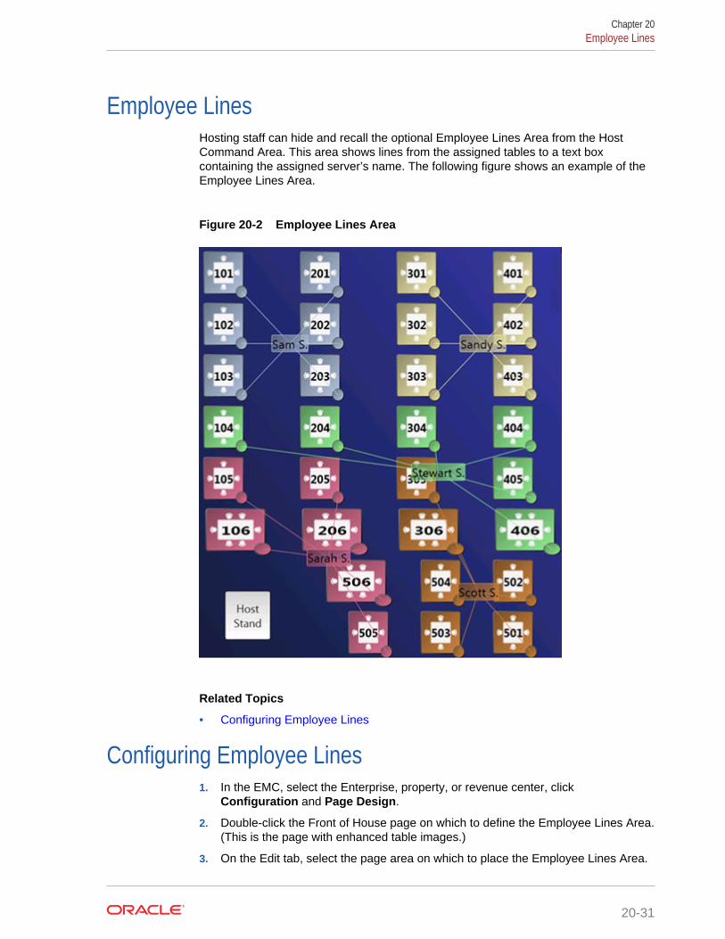
Employee LinesHosting staff can hide and recall the optional Employee Lines Area from the HostCommand Area. This area shows lines from the assigned tables to a text boxcontaining the assigned server’s name. The following figure shows an example of theEmployee Lines Area.
Figure 20-2 Employee Lines Area
Related Topics
• Configuring Employee Lines
Configuring Employee Lines1. In the EMC, select the Enterprise, property, or revenue center, click
Configuration and Page Design.
2. Double-click the Front of House page on which to define the Employee Lines Area.(This is the page with enhanced table images.)
3. On the Edit tab, select the page area on which to place the Employee Lines Area.
Chapter 20Employee Lines
20-31

Place the Employee Lines Area in the same content area on the page as the HostCommand Area and tables in order for the hosting staff to access the functionsand view information.
4. Select Other..., Table Management, and Employee Lines Area.
5. Adjust the size and placement of the Employee Lines Area to ensure that it coversall enhanced tables on the page. Tables that are not covered by the EmployeeLines Area do not show server assignment lines.
6. Click Save.
Related Topics
• Employee Lines
Section LayoutThe Section Layout contains controls to create and administer Seating SectionLayouts for table, section, and server assignments. Hosting staff can hide and recallthe optional Section Layout from the Host Command Area or from a separate page.Oracle Hospitality recommends creating a Section Layout on a separate page. Hostingstaff can easily assign tables to a section when:
• Tables are present on the same page as the Section Layout.
• Tables are accessible while editing a Section Layout.
The following figure shows an example of the Section Layout.
Figure 20-3 Section Layout
Chapter 20Section Layout
20-32

Related Topics
• Creating a Section Layout
Creating a Section Layout1. In the EMC, select the Enterprise, property, or revenue center, click
Configuration and Page Design.
2. Create the Front of House page on which to define the Section Layout.
3. Select Other..., Table Management, and Section Layout.
4. Adjust the Section Layout size to ensure that the text is visible to hosting staff. Thetext size scales with the Section Layout size.
5. Click Save.
Related Topics
• Section Layout
Creating Enhanced Dining TablesYou can use all functions of the Simphony Table Management System (TMS) usingenhanced dining tables. You cannot use legacy standard tables with TMS. Enhanceddining tables show overlays on the outer edges of the table that indicate status,coursing, and alerts.
1. In the EMC, select the Enterprise, property, or revenue center, clickConfiguration and Page Design.
2. Double-click the Front of House page on which to define enhanced dining tables.
3. On the Edit tab, select the page area on which to place the enhanced diningtables.
4. Select Other..., Table Management, and Dining Table (Enhanced).
5. Move and adjust the table size on the page. Leave space between tables on thepage layout to ensure visibility of indicators and table state. You can increase thegrid configuration on the page from 24 (default) to 48 using the Change Grid Sizelink.
6. Set the unique properties of the enhanced dining table:
a. Enter the table number in the Table # field.
This must match the Table Number set in the Tables module. See ConfiguringEnhanced Dining Tables for more information.
b. In the Next Page/Panel section, select the black Panel arrow, and then selectthe host page from the list.
c. (Optional) Enter a table number in the Legend field. If the Legend is blank, thetable number or name shown on the host page uses the table number or namedefined for the Table # field. If you want to use a different name or number forthe table, you can enter an override value in the Legend field.
7. Repeat Steps 4 through 6 to create additional enhanced dining tables.
8. Click Save.
Chapter 20Creating a Section Layout
20-33

Setting Table Management Functions in Check Detail1. In the EMC, select the Enterprise, property, or revenue center, click
Configuration and Page Design.
2. Double-click the Front of House page that contains the Check Detail area.
3. Select the Check Detail area on the page.
4. Select Show Seat Number to provide the workstation operator with a visualrepresentation of the seat number associated with a menu item or guest on thecheck detail area.
5. Select Enable Gestures to allow the workstation operator to access a menu ofoptions when long-pressing on the guest check.
The long-press options include:
• Change Item Seat
• Change Item Course
• View By Item Entry
• View By Seat
• View By Course
6. Select the view mode from the Initial View Mode drop-down.
This is the view shown when the workstation operator initially sees the guestcheck. Oracle recommends selecting the View By Seat mode for restaurants thatallow multiple loyalty accounts on a single guest check.
7. Click Save.
Creating the Employee Section Assignment Report Button1. In the EMC, select the Enterprise, property, or revenue center, click
Configuration and Page Design.
2. Open the Front of House page on which to place the Employee SectionAssignment Report button.
3. On the Edit tab, select the page area in which to define the button.
4. Click Button.
5. Position and size the button on the page. Use the Style arrow to change the color.
6. In the Legend field, enter the button name.
7. Select Ad Hoc Report from the Type drop-down.
8. Click the black arrow, select 44 – Employee Section Assignment Report fromthe report list, and click OK.
9. Click Save.
Chapter 20Setting Table Management Functions in Check Detail
20-34
Configuring Table Cancellation ReasonsYou can optionally create Reservation and Wait List Reasons to indicate why a guestcancels or abandons a table request.
1. In the EMC, select the Enterprise, property, or revenue center, click Descriptorsand TMS Reasons.
2. Enter a reason in the Text field. You can create a maximum of 32 reasons.
3. Click Save.
Setting Reservation Timing Parameters1. In the EMC, select the Enterprise, property, or revenue center, click Setup and
TMS Parameters.
2. On the Configuration tab, enter information in the following fields:
Table 20-16 Reservation Timing Fields
Field Description
Reservation to Waitlist Delay Enter how far in advance a reservationappears on the Wait List before thescheduled seating time. Reservation recordsthat are visible on the Wait List impact thequote times and table suggestions.
Maximum Reservation Notice (Days) Enter how far in advance a reservation canbe made. This value includes the currentbusiness day. For example, a value of 90indicates that guests can make reservationsno more than 90 days in advance.
Minimum Reservation Notice (Minutes) Enter the amount of advanced time whenreservations can no longer be made for thesame business day. For example, a value of30 indicates that guests cannot makereservations less than 30 minutes inadvance.
3. Select the appropriate options for reservation functions.
Table 20-17 Reservation Options
Option Description
Require Reason Code on Abandon/Cancel Select this option to have the applicationprompt the workstation operator to enter acancellation reason for the reservationrequest.
Enable Reservation Approval Select this option if you want the workstationoperator to obtain approval when creating areservation outside of a date or timeavailable in the Table Management System(TMS) inventory.
Chapter 20Configuring Table Cancellation Reasons
20-35
Table 20-17 (Cont.) Reservation Options
Option Description
Enable Create and Edit Buttons Select this option to show Create and Editbuttons following the Reservation List inOps. When you enable the buttons, theworkstation operator can also double-tap thescreen to create or edit reservations.
4. Click Save.
Related Topics
• Reservation List
• Table Management, Reservation, and Wait List Configuration Prerequisites
• Reservation Configuration Levels
Setting Wait List Timing Parameters1. In the EMC, select the Enterprise, property, or revenue center, click Setup and
TMS Parameters.
2. On the Configuration tab, enter information in the following fields:
Table 20-18 Wait List Timing Fields
Field Description
Reservation To Waitlist Delay Enter how far in advance a reservationappears on the Wait List before thescheduled seating time. Reservation recordsthat are visible on the Wait List impact thequote times and table suggestions.
Wait Quote Interval (Minutes) Enter the wait quote time increments (forexample, every 2 minutes or 5 minutes).
Auto Abandon Wait List Delay (Minutes) Enter the number of minutes that a tablerequest record remains on the Wait Listbefore the application automatically updatesit as Abandoned (for walk-ins) or No-Show(for reservations). The application removesthe record from the Wait List after reachingthis time threshold.
Wait Quote Alert Threshold (Minutes) Enter the number of minutes to elapsebefore flagging the table request on the WaitList as Overdue for seating. Enter 0 (zero) toflag the table request as soon as the timequote elapses.
3. Select the appropriate options to enable or disable wait list functions. The followingtable describes the options.
Chapter 20Setting Wait List Timing Parameters
20-36
Table 20-19 Wait List Options
Option Description
Require Reason Code on Abandon/Cancel Select this option to have the applicationprompt the workstation operator to enter areason for abandoning or cancelling a tablerequest.
Enable Wait List Chit Printing Select this option to print a chit when thehost staff creates or updates a tablerequest. The chit contains table requestinformation and the estimated wait time.
Enable Create and Edit Buttons Select this option to show Create and Editbuttons following the Wait List in Ops. Whenyou enable the buttons, the workstationoperator can also double-tap the screen tocreate or edit table requests.
4. Click Save.
Related Topics
• Wait List
• Table Management, Reservation, and Wait List Configuration Prerequisites
• Wait List Configuration Levels
Reservation PeriodsOptional Reservation Period settings control reservation inventory and allow walk-intable requests. They also define projected turn times for tables based on time andcover count. If the property does not take reservations, Oracle Hospitality recommendsconfiguring Reservation Periods so that hosting staff can use the Estimate Wait Quotefeature on the Wait List.
Setting Reservation Periods consists of completing the following tasks:
• Setting the reservation period timeframe
• Setting reservations intervals and covers
• Setting occupancy
• Setting seating capacity and quantity
• Setting anticipated turn times for tables
Related Topics
• Configuring Effectivity
• Configuring Acceptance Limits
• Configuring Occupancy Limits
• Configuring Seating Limits
• Configuring Target Turn Times
Chapter 20Reservation Periods
20-37
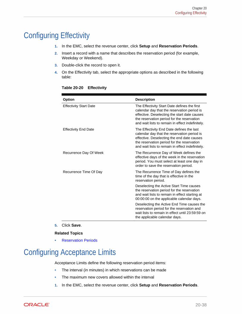
Configuring Effectivity1. In the EMC, select the revenue center, click Setup and Reservation Periods.
2. Insert a record with a name that describes the reservation period (for example,Weekday or Weekend).
3. Double-click the record to open it.
4. On the Effectivity tab, select the appropriate options as described in the followingtable:
Table 20-20 Effectivity
Option Description
Effectivity Start Date The Effectivity Start Date defines the firstcalendar day that the reservation period iseffective. Deselecting the start date causesthe reservation period for the reservationand wait lists to remain in effect indefinitely.
Effectivity End Date The Effectivity End Date defines the lastcalendar day that the reservation period iseffective. Deselecting the end date causesthe reservation period for the reservationand wait lists to remain in effect indefinitely.
Recurrence Day Of Week The Recurrence Day of Week defines theeffective days of the week in the reservationperiod. You must select at least one day inorder to save the reservation period.
Recurrence Time Of Day The Recurrence Time of Day defines thetime of the day that is effective in thereservation period.
Deselecting the Active Start Time causesthe reservation period for the reservationand wait lists to remain in effect starting at00:00:00 on the applicable calendar days.
Deselecting the Active End Time causes thereservation period for the reservation andwait lists to remain in effect until 23:59:59 onthe applicable calendar days.
5. Click Save.
Related Topics
• Reservation Periods
Configuring Acceptance LimitsAcceptance Limits define the following reservation period items:
• The interval (in minutes) in which reservations can be made
• The maximum new covers allowed within the interval
1. In the EMC, select the revenue center, click Setup and Reservation Periods.
Chapter 20Configuring Effectivity
20-38
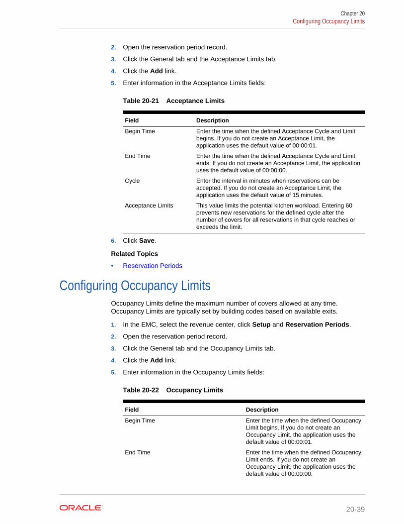
2. Open the reservation period record.
3. Click the General tab and the Acceptance Limits tab.
4. Click the Add link.
5. Enter information in the Acceptance Limits fields:
Table 20-21 Acceptance Limits
Field Description
Begin Time Enter the time when the defined Acceptance Cycle and Limitbegins. If you do not create an Acceptance Limit, theapplication uses the default value of 00:00:01.
End Time Enter the time when the defined Acceptance Cycle and Limitends. If you do not create an Acceptance Limit, the applicationuses the default value of 00:00:00.
Cycle Enter the interval in minutes when reservations can beaccepted. If you do not create an Acceptance Limit, theapplication uses the default value of 15 minutes.
Acceptance Limits This value limits the potential kitchen workload. Entering 60prevents new reservations for the defined cycle after thenumber of covers for all reservations in that cycle reaches orexceeds the limit.
6. Click Save.
Related Topics
• Reservation Periods
Configuring Occupancy LimitsOccupancy Limits define the maximum number of covers allowed at any time.Occupancy Limits are typically set by building codes based on available exits.
1. In the EMC, select the revenue center, click Setup and Reservation Periods.
2. Open the reservation period record.
3. Click the General tab and the Occupancy Limits tab.
4. Click the Add link.
5. Enter information in the Occupancy Limits fields:
Table 20-22 Occupancy Limits
Field Description
Begin Time Enter the time when the defined OccupancyLimit begins. If you do not create anOccupancy Limit, the application uses thedefault value of 00:00:01.
End Time Enter the time when the defined OccupancyLimit ends. If you do not create anOccupancy Limit, the application uses thedefault value of 00:00:00.
Chapter 20Configuring Occupancy Limits
20-39
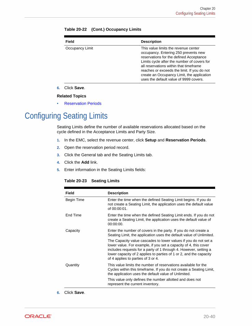
Table 20-22 (Cont.) Occupancy Limits
Field Description
Occupancy Limit This value limits the revenue centeroccupancy. Entering 250 prevents newreservations for the defined AcceptanceLimits cycle after the number of covers forall reservations within that timeframereaches or exceeds the limit. If you do notcreate an Occupancy Limit, the applicationuses the default value of 9999 covers.
6. Click Save.
Related Topics
• Reservation Periods
Configuring Seating LimitsSeating Limits define the number of available reservations allocated based on thecycle defined in the Acceptance Limits and Party Size.
1. In the EMC, select the revenue center, click Setup and Reservation Periods.
2. Open the reservation period record.
3. Click the General tab and the Seating Limits tab.
4. Click the Add link.
5. Enter information in the Seating Limits fields:
Table 20-23 Seating Limits
Field Description
Begin Time Enter the time when the defined Seating Limit begins. If you donot create a Seating Limit, the application uses the default valueof 00:00:01.
End Time Enter the time when the defined Seating Limit ends. If you do notcreate a Seating Limit, the application uses the default value of00:00:00.
Capacity Enter the number of covers in the party. If you do not create aSeating Limit, the application uses the default value of Unlimited.
The Capacity value cascades to lower values if you do not set alower value. For example, if you set a capacity of 4, this coverincludes requests for a party of 1 through 4. However, setting alower capacity of 2 applies to parties of 1 or 2, and the capacityof 4 applies to parties of 3 or 4.
Quantity This value limits the number of reservations available for theCycles within this timeframe. If you do not create a Seating Limit,the application uses the default value of Unlimited.
This value only defines the number allotted and does notrepresent the current inventory.
6. Click Save.
Chapter 20Configuring Seating Limits
20-40

Related Topics
• Reservation Periods
Configuring Target Turn TimesTarget Turn Times define the target time from seating to request completion for aseated party. Target Turn Times also affect the following seating-related operations:
• Prevent reservation overbooking
• Estimate wait times for walk-in table requests
• Anticipate the tables that will be available in order to distribute the table seatingappropriately
1. In the EMC, select the revenue center, click Setup and Reservation Periods.
2. Open the reservation period record.
3. Click the General tab and the Target Turn Times tab.
4. Click the Add link.
5. Enter information in the Target Turn Times fields:
Table 20-24 Target Turn Times
Field Description
Begin Time Enter the time when the defined CoverCount and Target Turn Time begins. If youdo not create a Target Turn Time, theapplication uses the default value of00:00:01.
End Time Enter the time when the defined CoverCount and Target Turn Time ends. If you donot create a Target Turn Time, theapplication uses the default value of00:00:00.
Cover Count Enter the number of covers seated at thetable. If you do not create a Target TurnTime, the application uses the default valueof Unlimited.
The Cover Count value cascades to lowervalues if you do not set a lower value. Forexample, if you set a cover count of 4, thiscover includes requests for a party of 1through 4. However, setting a lower capacityof 2 applies to parties of 1 or 2, and thecapacity of 4 applies to parties of 3 or 4.
Chapter 20Configuring Target Turn Times
20-41

Table 20-24 (Cont.) Target Turn Times
Field Description
Minutes Enter the anticipated turn time (in minutes)for a table seating of the defined CoverCount during the specified timeframe. If youdo not create a Target Turn Time, theapplication uses the default value of 60.
For example, if you enter 45, table seatingsthat encompass the defined cover countduring the timeframe assume the seatingrequest is 45 minutes in duration.
6. Click Save.
Related Topics
• Reservation Periods
Table Management Configuration LevelsThe following table shows the hierarchy levels within the Enterprise ManagementConsole (EMC) that allow you to configure table management operations.
Table 20-25 Table Management Configuration Levels
ConfigurationModule
Enterprise Property Revenue Center Zone
Content X X X X
Dining TableClasses
X X X
EmployeeMaintenance
X X X
TMS Parameters X X X X
TMS Privileges X
ReservationPeriods
X
TMS TableAttributes
X X X
KDS/DiningCourse Colors
X X X
Loyalty Module X X X X
Page Design X X X X
Properties X
Seating SectionTemplates
X
Sections X
Tables X
Chapter 20Table Management Configuration Levels
20-42
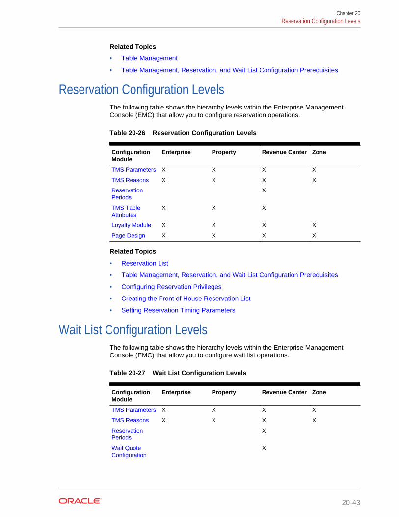
Related Topics
• Table Management
• Table Management, Reservation, and Wait List Configuration Prerequisites
Reservation Configuration LevelsThe following table shows the hierarchy levels within the Enterprise ManagementConsole (EMC) that allow you to configure reservation operations.
Table 20-26 Reservation Configuration Levels
ConfigurationModule
Enterprise Property Revenue Center Zone
TMS Parameters X X X X
TMS Reasons X X X X
ReservationPeriods
X
TMS TableAttributes
X X X
Loyalty Module X X X X
Page Design X X X X
Related Topics
• Reservation List
• Table Management, Reservation, and Wait List Configuration Prerequisites
• Configuring Reservation Privileges
• Creating the Front of House Reservation List
• Setting Reservation Timing Parameters
Wait List Configuration LevelsThe following table shows the hierarchy levels within the Enterprise ManagementConsole (EMC) that allow you to configure wait list operations.
Table 20-27 Wait List Configuration Levels
ConfigurationModule
Enterprise Property Revenue Center Zone
TMS Parameters X X X X
TMS Reasons X X X X
ReservationPeriods
X
Wait QuoteConfiguration
X
Chapter 20Reservation Configuration Levels
20-43
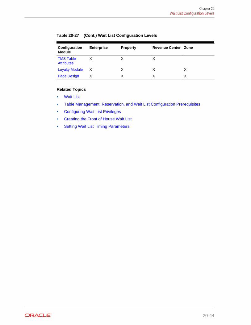
Table 20-27 (Cont.) Wait List Configuration Levels
ConfigurationModule
Enterprise Property Revenue Center Zone
TMS TableAttributes
X X X
Loyalty Module X X X X
Page Design X X X X
Related Topics
• Wait List
• Table Management, Reservation, and Wait List Configuration Prerequisites
• Configuring Wait List Privileges
• Creating the Front of House Wait List
• Setting Wait List Timing Parameters
Chapter 20Wait List Configuration Levels
20-44

21Enterprise Cash Management
You can use the Enterprise Cash Management (ECM) module to track the amount ofcash located within a property. You can track the physical currency that is collectedand the exact location of funds (for example, in a till, safe, bank deposit, or serverbank). ECM follows currency as it progresses through the following phases:
• Enters the building (for example, cash tender, paid-in, or change order receivedfrom the bank)
• Moves through the building (for example, from tills to a safe or bank deposit)
• Leaves the building (for example, paid out to a vendor, change given to a guest, ortaken to a bank for deposit)
As money flows through the operation, ECM logs all currency actions for reporting andauditing purposes.
• Configuring Data Retention Limits
• Specifying Ad Hoc Reports
• Configuring ECM Privileges
• Allowing Users to View Blind Totals
• Allowing Assigned Receptacle Access
• Configuring Accounting Methods for Users
• Allowing Users to Override Employee Class Options
• Tracking Tender Transaction Items
• Tracking Service Charge Transactions
• Tracking Discount Transactions
• Creating, Editing, and Deleting Cash Management Reasons
• Cash Management Classes
• Adding Transaction Items
• Adding Counting Units
• Cash Pull Threshold Set
• Creating, Editing, and Deleting a Cash Pull Threshold Set
• Cash Count Threshold Set
• Creating, Editing, and Deleting a Cash Count Threshold Set
• PAR Level Set
• Creating, Editing, and Deleting a PAR Level Set
• Count Sheet
• Creating, Editing, and Deleting a Count Sheet
• Adding and Deleting a Page
21-1

• Adding and Deleting a Group
• Adding and Deleting a Unit
• Sorting and Modifying the Order of Pages, Groups, and Units
• Viewing the Totals Page
• Creating, Editing, and Deleting an Account
• Creating, Editing, and Deleting a Vendor
• Creating and Editing a Template
• Creating, Editing, and Deactivating Receptacles
• Setting Cash Management Parameters
• Creating Front of House Screens
• Configuring a Smart Key on a Workstation
• Configuring a Till Through Extensibility
• ECM Reporting
• ECM Enterprise Reports
• Assigning Enterprise Reports
• Creating ECM Property Reports
• ECM Workstation Hardware
• Enterprise Cash Management Configuration Levels
Related Topics
• Tracking Tender Transaction Items
• Tracking Service Charge Transactions
• Tracking Discount Transactions
• ECM Workstation Hardware
• Enterprise Cash Management Configuration Levels
Configuring Data Retention LimitsYou can set the length of time Enterprise Cash Management (ECM) data remainspresent in the database at the enterprise and property levels.
1. In the Enterprise Management Console (EMC), select the Enterprise level, clickSetup, Enterprise Parameters, and Miscellaneous.
2. In the Purging section, set the Days To Keep for ECM Transaction Detail. This isthe number of days from the time a transaction is reported to the enterprise thatthe application retains it for use in reporting and auditing (for example, from 1 dayto 999 days). After the number of days to keep expires, a scheduled event purgesthe ECM data.
3. Click Save.
Chapter 21Configuring Data Retention Limits
21-2
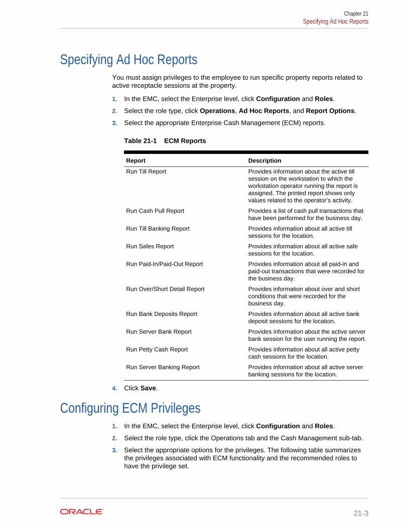
Specifying Ad Hoc ReportsYou must assign privileges to the employee to run specific property reports related toactive receptacle sessions at the property.
1. In the EMC, select the Enterprise level, click Configuration and Roles.
2. Select the role type, click Operations, Ad Hoc Reports, and Report Options.
3. Select the appropriate Enterprise Cash Management (ECM) reports.
Table 21-1 ECM Reports
Report Description
Run Till Report Provides information about the active tillsession on the workstation to which theworkstation operator running the report isassigned. The printed report shows onlyvalues related to the operator’s activity.
Run Cash Pull Report Provides a list of cash pull transactions thathave been performed for the business day.
Run Till Banking Report Provides information about all active tillsessions for the location.
Run Safes Report Provides information about all active safesessions for the location.
Run Paid-In/Paid-Out Report Provides information about all paid-in andpaid-out transactions that were recorded forthe business day.
Run Over/Short Detail Report Provides information about over and shortconditions that were recorded for thebusiness day.
Run Bank Deposits Report Provides information about all active bankdeposit sessions for the location.
Run Server Bank Report Provides information about the active serverbank session for the user running the report.
Run Petty Cash Report Provides information about all active pettycash sessions for the location.
Run Server Banking Report Provides information about all active serverbanking sessions for the location.
4. Click Save.
Configuring ECM Privileges1. In the EMC, select the Enterprise level, click Configuration and Roles.
2. Select the role type, click the Operations tab and the Cash Management sub-tab.
3. Select the appropriate options for the privileges. The following table summarizesthe privileges associated with ECM functionality and the recommended roles tohave the privilege set.
Chapter 21Specifying Ad Hoc Reports
21-3
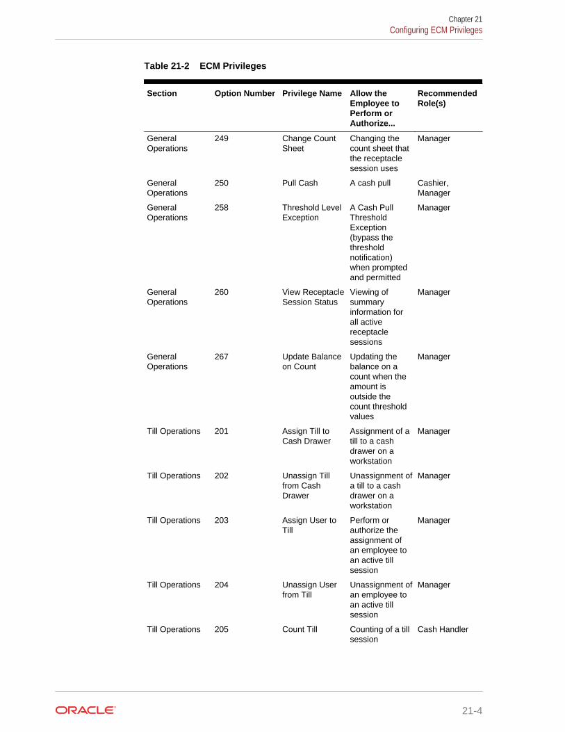
Table 21-2 ECM Privileges
Section Option Number Privilege Name Allow theEmployee toPerform orAuthorize...
RecommendedRole(s)
GeneralOperations
249 Change CountSheet
Changing thecount sheet thatthe receptaclesession uses
Manager
GeneralOperations
250 Pull Cash A cash pull Cashier,Manager
GeneralOperations
258 Threshold LevelException
A Cash PullThresholdException(bypass thethresholdnotification)when promptedand permitted
Manager
GeneralOperations
260 View ReceptacleSession Status
Viewing ofsummaryinformation forall activereceptaclesessions
Manager
GeneralOperations
267 Update Balanceon Count
Updating thebalance on acount when theamount isoutside thecount thresholdvalues
Manager
Till Operations 201 Assign Till toCash Drawer
Assignment of atill to a cashdrawer on aworkstation
Manager
Till Operations 202 Unassign Tillfrom CashDrawer
Unassignment ofa till to a cashdrawer on aworkstation
Manager
Till Operations 203 Assign User toTill
Perform orauthorize theassignment ofan employee toan active tillsession
Manager
Till Operations 204 Unassign Userfrom Till
Unassignment ofan employee toan active tillsession
Manager
Till Operations 205 Count Till Counting of a tillsession
Cash Handler
Chapter 21Configuring ECM Privileges
21-4
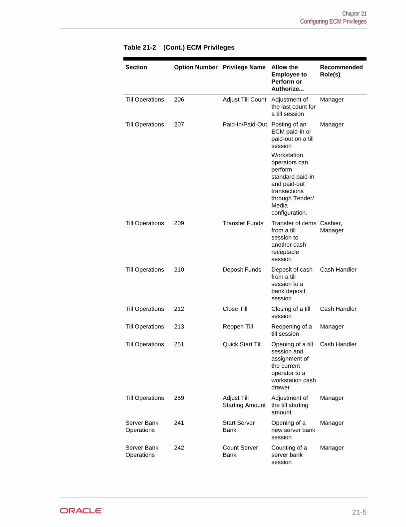
Table 21-2 (Cont.) ECM Privileges
Section Option Number Privilege Name Allow theEmployee toPerform orAuthorize...
RecommendedRole(s)
Till Operations 206 Adjust Till Count Adjustment ofthe last count fora till session
Manager
Till Operations 207 Paid-In/Paid-Out Posting of anECM paid-in orpaid-out on a tillsession
Workstationoperators canperformstandard paid-inand paid-outtransactionsthrough Tender/Mediaconfiguration.
Manager
Till Operations 209 Transfer Funds Transfer of itemsfrom a tillsession toanother cashreceptaclesession
Cashier,Manager
Till Operations 210 Deposit Funds Deposit of cashfrom a tillsession to abank depositsession
Cash Handler
Till Operations 212 Close Till Closing of a tillsession
Cash Handler
Till Operations 213 Reopen Till Reopening of atill session
Manager
Till Operations 251 Quick Start Till Opening of a tillsession andassignment ofthe currentoperator to aworkstation cashdrawer
Cash Handler
Till Operations 259 Adjust TillStarting Amount
Adjustment ofthe till startingamount
Manager
Server BankOperations
241 Start ServerBank
Opening of anew server banksession
Manager
Server BankOperations
242 Count ServerBank
Counting of aserver banksession
Manager
Chapter 21Configuring ECM Privileges
21-5
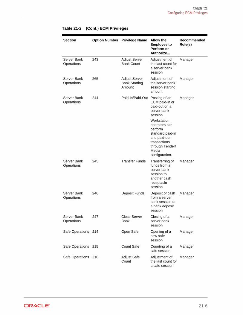
Table 21-2 (Cont.) ECM Privileges
Section Option Number Privilege Name Allow theEmployee toPerform orAuthorize...
RecommendedRole(s)
Server BankOperations
243 Adjust ServerBank Count
Adjustment ofthe last count fora server banksession
Manager
Server BankOperations
265 Adjust ServerBank StartingAmount
Adjustment ofthe server banksession startingamount
Manager
Server BankOperations
244 Paid-In/Paid-Out Posting of anECM paid-in orpaid-out on aserver banksession
Workstationoperators canperformstandard paid-inand paid-outtransactionsthrough Tender/Mediaconfiguration.
Manager
Server BankOperations
245 Transfer Funds Transferring offunds from aserver banksession toanother cashreceptaclesession
Manager
Server BankOperations
246 Deposit Funds Deposit of cashfrom a serverbank session toa bank depositsession
Manager
Server BankOperations
247 Close ServerBank
Closing of aserver banksession
Manager
Safe Operations 214 Open Safe Opening of anew safesession
Manager
Safe Operations 215 Count Safe Counting of asafe session
Manager
Safe Operations 216 Adjust SafeCount
Adjustment ofthe last count fora safe session
Manager
Chapter 21Configuring ECM Privileges
21-6

Table 21-2 (Cont.) ECM Privileges
Section Option Number Privilege Name Allow theEmployee toPerform orAuthorize...
RecommendedRole(s)
Safe Operations 217 Paid-In/Paid-Out Posting of anECM paid-in orpaid-out on asafe session
Workstationoperators canperformstandard paid-inand paid-outtransactionsthrough Tender/Mediaconfiguration.
Manager
Safe Operations 218 Transfer Funds Transferring offunds from asafe session toanother cashreceptaclesession
Manager
Safe Operations 219 Deposit Funds Deposit of cashfrom a safesession to abank depositsession
Manager
Safe Operations 220 Close Safe Closing of a safesession
Manager
Safe Operations 261 Add Funds toSafe
Adding newfunds into ECMthrough a safereceptacle
Manager
Safe Operations 262 Remove Fundsfrom Safe
Removing fundsfrom ECMthrough a safereceptacle
Manager
Petty CashOperations
222 Open PettyCash
Opening of anew petty cashsession
Manager
Petty CashOperations
223 Count PettyCash
Counting of apetty cashsession
Manager
Petty CashOperations
224 Adjust PettyCash Count
Adjustment ofthe last pettycash sessioncount
Manager
Chapter 21Configuring ECM Privileges
21-7
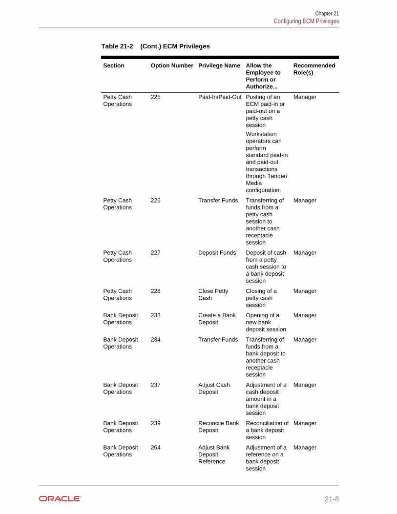
Table 21-2 (Cont.) ECM Privileges
Section Option Number Privilege Name Allow theEmployee toPerform orAuthorize...
RecommendedRole(s)
Petty CashOperations
225 Paid-In/Paid-Out Posting of anECM paid-in orpaid-out on apetty cashsession
Workstationoperators canperformstandard paid-inand paid-outtransactionsthrough Tender/Mediaconfiguration.
Manager
Petty CashOperations
226 Transfer Funds Transferring offunds from apetty cashsession toanother cashreceptaclesession
Manager
Petty CashOperations
227 Deposit Funds Deposit of cashfrom a pettycash session toa bank depositsession
Manager
Petty CashOperations
228 Close PettyCash
Closing of apetty cashsession
Manager
Bank DepositOperations
233 Create a BankDeposit
Opening of anew bankdeposit session
Manager
Bank DepositOperations
234 Transfer Funds Transferring offunds from abank deposit toanother cashreceptaclesession
Manager
Bank DepositOperations
237 Adjust CashDeposit
Adjustment of acash depositamount in abank depositsession
Manager
Bank DepositOperations
239 Reconcile BankDeposit
Reconciliation ofa bank depositsession
Manager
Bank DepositOperations
264 Adjust BankDepositReference
Adjustment of areference on abank depositsession
Manager
Chapter 21Configuring ECM Privileges
21-8

Table 21-2 (Cont.) ECM Privileges
Section Option Number Privilege Name Allow theEmployee toPerform orAuthorize...
RecommendedRole(s)
Change OrderOperations
230 Create ChangeOrder
Creation of anew ChangeOrder requestfrom a safesession
Manager
4. Click Save.
Allowing Users to View Blind TotalsIn some cases, you can require that workstation operators view the difference betweenthe amount entered during a count and the amount expected by applicationtransaction activity. Selecting View Blind Totals allows workstation operators withinthe Employee Class to view application expected values and the difference on thecount sheet. When an over or short condition exists, the workstation operator canselect the reason for the variance.
1. In the EMC, select the property, click Configuration and Employee Classes.
2. Select the role type and click Operator Options.
3. Select 25 - View Blind Totals.
4. Click Save.
Allowing Assigned Receptacle AccessEnterprise Cash Management (ECM) requires that a workstation operator be assignedto a till or server bank receptacle session to perform transactions against the session.Managers need access to work within these receptacle sessions without beingassigned to the sessions. You can create an Employee Class for managementworkstation operators with a configuration set that allows them to perform transactionsagainst the till or server banking session without prior assignment.
1. In the EMC, select the property, click Configuration and Employee Classes.
2. Select the role type and click Operator Options.
3. Select 26 - Allow Assigned Receptacle Access if you want workstationoperators to view and perform transactions for till and server bank receptacleswhen the operator is not the owner or an assigned user.
4. Click Save.
Configuring Accounting Methods for UsersYou can specify the type of accounting method a workstation operator uses to trackcash management activities. The method you select determines the type of front ofhouse receptacles the workstation operator can access.
1. In the EMC, select the property, click Configuration and Employee Classes.
Chapter 21Allowing Users to View Blind Totals
21-9

2. Select the role type.
3. Select the appropriate Cash Management Accounting Method on the Generaltab:
• None – Selecting this option prevents the workstation operator from executingtill or server banking transactions.
• Till Banking – Select this option for workstation operators that maintain andwork from a till that is assigned to a workstation (for example, bartenders andcashiers).
• Server Banking – Select this option for workstation operators who maintainand work from an individual server bank on their person (for example, serverswho are responsible for accepting payment on guest checks). This accountingmethod does not allow workstation operators to perform transaction activity ona till session when the operator is an assigned user.
4. Click Save.
Allowing Users to Override Employee Class OptionsYou can optionally override Employee Class configuration options for individualworkstation operators.
1. In the EMC, select the Enterprise, zone, property, or revenue center, clickConfiguration and Employee Maintenance.
2. Select a property and revenue center, and click Search.
3. Select Operator Records.
4. Select Override Class Options for an employee.
5. Select the override options.
Table 21-3 Override Employee Class Options
Option Description
Options When you select Override Class Options,the application automatically selects theOperator Options for the employee’srevenue center. You can override the option25 - View Blind Totals here.
Cash Management Accounting Method When you select a Cash Managementaccounting method here for an employee,you override the accounting method set inthe Employee Class module.
Cash Drawer This option indicates the cash drawer that isdefined for the workstation operator withinthe revenue center: 0 (no cash drawerassignment, user prompted), 1, or 2. TheQuick Start till operation uses the definedcash drawer.
6. Click Save.
Chapter 21Allowing Users to Override Employee Class Options
21-10

Tracking Tender Transaction ItemsYou can identify tender media transaction items (for example, cash, check, and othercurrency based tenders) that you want Enterprise Cash Management (ECM) to track.
1. In the EMC, select the Enterprise, zone, or property, click Configuration andTender/Media.
2. Double-click the tender media record.
3. Click the Options tab and the Ops Behavior tab.
4. Select the appropriate Tender options.
• 91 – Cash Management Transaction Item – Select this option to include thetender record in Cash Management tracking and reporting.
• (Optional) 92 – Affects Cash Pull Threshold – Select this option if you wanttransactions performed for this tender record to affect the Cash Pull ThresholdSet balance. Select this option for tender records that would represent a loss ifthey are lost or stolen (for example, cash and checks). You must select option91 to use option 92.
5. Click Save.
Related Topics
• Enterprise Cash Management
• ECM Workstation Hardware
• Enterprise Cash Management Configuration Levels
Tracking Service Charge TransactionsYou can identify service charge transactions (for example, gift card sales) that youwant Enterprise Cash Management (ECM) to track.
1. In the EMC, select the Enterprise, zone, or property, click Configuration andService Charges.
2. Double-click the service charge.
3. Select 28 - Cash Management Transaction Item to include the service chargerecord in Cash Management tracking and reporting.
4. Click Save.
Related Topics
• Enterprise Cash Management
• ECM Workstation Hardware
• Enterprise Cash Management Configuration Levels
Tracking Discount TransactionsYou can identify discount transactions (for example, coupons and promotionalvouchers) that you want Enterprise Cash Management (ECM) to track.
Chapter 21Tracking Tender Transaction Items
21-11

1. In the EMC, select the Enterprise, zone, or property, click Configuration andDiscounts.
2. Double-click the discount.
3. Select the appropriate discount options on the General tab:
• 33 - Cash Management Transaction Item – Select this option to include thediscount record in Cash Management tracking and reporting.
• (Optional) 34 - Affects Cash Pull Threshold – Select this option if you wanttransactions performed for this discount record to increase the value in areceptacle. You must select option 33 to use option 34.
4. Click Save.
Related Topics
• Enterprise Cash Management
• ECM Workstation Hardware
• Enterprise Cash Management Configuration Levels
Creating, Editing, and Deleting Cash Management ReasonsCertain Enterprise Cash Management (ECM) operations allow (and sometimesrequire) the workstation operator to enter a reason for performing the operation. Forexample, workstation operators must provide a reason for adjusting transactions.
1. In the EMC, select the Enterprise, zone, property, or revenue center, clickDescriptors and Cash Management Reasons.
2. Highlight the Cash Management transaction and select Add Reason.
3. Enter the reason name, based on the following guidelines:
• You can define multiple reasons for each transaction.
• You can use each reason name only once per transaction type.
4. Click Save.
5. If you want to edit a reason, highlight the reason record, change the reason name,and click Save.
After you change a reason, the new reason appears when viewing historicalreporting activity.
6. If you want to delete a reason, highlight the reason record and select DeleteReason.
The application allows you to delete only reasons that are not referenced inhistorical reporting activity.
Cash Management ClassesYou can configure a Cash Management class for the type of records you want to trackin ECM. You must define a class for the currency to be accepted, and to track non-cash items in ECM (for example, credit card vouchers, gift cards, and coupons).
Within the Cash Management class, you can specify unique counting units associatedwith the transaction items within the class (for example, bank notes and coins).
Chapter 21Creating, Editing, and Deleting Cash Management Reasons
21-12

Related Topics
• Adding Transaction Items
• Adding Counting Units
Adding Transaction ItemsYou must map transaction items (for example, tenders) to the Cash Managementclass to measure their impact (increase or decrease) on the balance of alltransactions. Enterprise Cash Management (ECM) tracks only transaction items thatare mapped to the class.
1. In the EMC, select the Enterprise, zone, property, or revenue center, click Setupand Cash Management Classes.
2. Insert a Cash Management class record and then double-click it.
3. Select Transaction Items.
4. Enter the name of the class to track in ECM (for example, Cash, US Dollars,Vouchers, and so on).
5. Select an available Currency from the list to associate with the Cash Managementclass. You can only associate the currency with a single class. Select 0 - None fornon-currency tracking (for example, vouchers and stored value cards) as theseitems are always based on the property’s local currency.
6. Select Allow in Bank Deposit if you want transaction items mapped with thisCash Management class to be included in bank deposits (for example, cash,personal checks, and travelers checks).
7. Select Add Transaction Item.
8. Select a Transaction Item Type.
9. Select a Transaction Item. The Cash Management Transaction Item options inthe tender, service charge, or discount determine the items that appear in thisTransaction Item list. You can use each transaction item only once per class.
10. Click Save.
Related Topics
• Cash Management Classes
Adding Counting UnitsAfter you add a denomination unit to a Cash Management class, Enterprise CashManagement (ECM) includes the unit when building Count Sheets and PAR LevelSets. The following figure shows an example of the units mapping setup.
Chapter 21Adding Transaction Items
21-13

Figure 21-1 Counting Units
1. Select Counting Units.
2. Select Add Unit.
3. Enter the name of the unit (for example, Pennies, Fives, Twenties, TravelersChecks, and so on).
4. When you select Denominated, the unit has a consistent cash value (for example,notes and coins). Do not select this option for this transaction items that haveinconsistent cash values (for example, personal checks, credit cards, and giftcards).
5. If the unit is denominated, the Numerator defines the units value relative to thebase currency unit. For example, when the base currency is US dollars, the basecurrency unit is 1 ($1.00).
6. If the unit is denominated, the Denominator defines the number of units relative tothe base currency unit. For example, when the base currency is US dollars, thebase currency unit is 1 ($1.00).
7. After you enter the numerator and denominator, the Value field shows thecalculated value per unit.
8. Click Save.
Related Topics
• Cash Management Classes
Cash Pull Threshold SetThe Cash Pull Threshold Set optionally provides a group of balance-based levels tocompare against a till or server banking session during a transaction. The thresholdset indicates when notifications should take place for cash pulls to minimize the risk bylimiting the amount of cash circulating in the front of house. You can add one or morethreshold levels to a Cash Pull Threshold Set.
Related Topics
• Creating, Editing, and Deleting a Cash Pull Threshold Set
Chapter 21Cash Pull Threshold Set
21-14
Creating, Editing, and Deleting a Cash Pull Threshold Set1. In the EMC, select the Enterprise, zone, property, or revenue center, click Setup
and Cash Pull Threshold Sets.
2. Insert a record, enter the name of the Cash Pull Threshold Set and click OK.
3. Double-click the record to open it.
4. Enter the Chit Quantity.
This is the number of chits that print when a workstation operator performs a cashpull. A cash pull chit represents the funds that are removed from the till or serverbank.
5. Select Add and then enter the name of the threshold set.
The name is part of the notification that appears in the application.
6. Enter the Amount.
This is the amount-based threshold that elevates the cash pull notification to thethreshold level. If you configure more than one threshold level, subsequentamounts cannot be equal to or lower than the previous cash pull amount in thesame set.
7. When you select Approval, a workstation operator with the Threshold LevelException privilege can authorize the operator to ignore the exception and allowthem to process transactions against the receptacle without performing a cashpull.
8. Click Save.
9. If you want to edit a cash pull threshold set, highlight the record, change thevalues, and click Save.
You cannot edit the last defined level. This requires the workstation operator toperform a cash pull first in order to execute additional activities against the till orserver bank later.
10. If you want to delete a cash pull threshold set, highlight the record and selectDelete.
You cannot delete a Cash Pull Threshold Set associated with one or moretemplates.
Related Topics
• Cash Pull Threshold Set
Cash Count Threshold SetThe Cash Count Threshold Set optionally provides an allowable variance threshold forcountable receptacles. The threshold is the difference between counted totals andexpected totals. The threshold indicates the overage and shortage amounts allowed tocomplete a receptacle count. You can add one or more cash count threshold sets to acount sheet.
Related Topics
• Creating, Editing, and Deleting a Cash Count Threshold Set
Chapter 21Creating, Editing, and Deleting a Cash Pull Threshold Set
21-15

Creating, Editing, and Deleting a Cash Count Threshold Set1. In the EMC, select the Enterprise, zone, property, or revenue center, click Setup
and Cash Count Threshold Sets.
2. Add a Cash Count Threshold Set, enter the name, and click OK.
3. Enter the Short amount.
This value is the minimum variance amount allowed to complete the receptaclecount.
4. Enter the Over amount.
This value is the maximum variance amount allowed to complete the receptaclecount.
5. Enter the number of Max Count Attempts.
This value limits the number of times a workstation operator can attempt to submita count when the count is over or short beyond the defined threshold.
6. Click Save.
7. If you want to edit a cash count threshold set, highlight the record, change thevalues, and click Save.
8. If you want to delete a cash count threshold set, highlight the record and selectDelete.
You cannot delete a Cash Count Threshold Set associated with one or moretemplates.
Related Topics
• Cash Count Threshold Set
PAR Level SetPeriodic Automatic Replenishment (PAR) Level Sets specify the suggested quantity tomaintain of each currency denomination kept in a safe (for example, rolls of coins orquantity of a denominated note). PAR Level Sets are comprised of count units drawnfrom the list of denominated items in a Cash Management class. The PAR determinesthe values required when issuing a Change Order request to return the receptacleback to the PAR based on the last known count of the receptacle. The use of a PARLevel Set is optional.
Related Topics
• Creating, Editing, and Deleting a PAR Level Set
Creating, Editing, and Deleting a PAR Level Set1. In the EMC, select the Enterprise, zone, property, or revenue center, click Setup
and PAR Level Sets.
2. Insert a record and enter the PAR Level Set name.
3. Double-click the record to open it.
Chapter 21Creating, Editing, and Deleting a Cash Count Threshold Set
21-16

4. Select the CM Class.
The CM Class list includes all Cash Management classes that you created. TheseCash Management classes contain the units that are allowed within the PAR LevelSet.
5. Add a Counting Unit using one of the following methods:
• Select Add All Units to have ECM add all defined units for the CashManagement class to the PAR Level.
• Select Add Unit to manually add specific units.
6. For each of the defined units, enter the quantity of units to maintain as part of thePAR Level Set for each day of the week.
7. Click Save.
8. If you want to edit a PAR Level Set, highlight the record, change the values, andclick Save.
9. If you want to delete a PAR Level Set, highlight the record and select Delete.
You cannot delete a PAR Level Set associated with one or more templates.
Related Topics
• PAR Level Set
Count SheetA workstation operator uses a Count Sheet during the physical counting of areceptacle session. Create unique Count Sheets to determine the items and order inwhich a count is performed, as well as the format for the printed Count Sheet results.Creating a Count Sheet is similar to building a report.
Related Topics
• Creating, Editing, and Deleting a Count Sheet
• Adding and Deleting a Page
• Adding and Deleting a Group
• Adding and Deleting a Unit
• Sorting and Modifying the Order of Pages, Groups, and Units
• Viewing the Totals Page
Creating, Editing, and Deleting a Count Sheet1. In the EMC, select the Enterprise, zone, property, or revenue center, click Setup
and Count Sheets.
2. Insert a record, enter a unique name for the Count Sheet, and click OK.
3. Click Save.
4. If you want to edit a count sheet, highlight the count sheet record, change thevalues, and click Save.
When you change a count sheet, the application removes all units associated withthe group.
Chapter 21Count Sheet
21-17

5. If you want to delete a count sheet, highlight the record and select Delete.
You cannot delete a Count Sheet associated with one or more templates.
Related Topics
• Count Sheet
Adding and Deleting a PageA Count Sheet Page is similar to a chapter in a report. Pages allows you to see totalsfor all values counted within the page.
1. Select Add in the Pages section.
2. Enter a name for each page (for example, Cash and Vouchers).
3. If you want to delete a page, highlight the page name record and select Delete.
The application deletes all units associated with a group for the selected pagealong with the page.
4. Click Save.
Related Topics
• Count Sheet
Adding and Deleting a GroupTransaction Items are reported in Count Sheet Groups. Groups also allow you to seetotals for all values counted within the group.
1. Highlight a page.
2. Select Add in the Groups section.
3. Enter a name for each group. As an example, you can have a Cash page with thegroups Notes (paper currency) and Coins.
4. Select the Cash Management Class for each group. When you select a value fromthe Class drop-down, the Name column shows the name of the class if it was notpreviously entered. Change the Name value to show its representation on thecount sheet screen view and print copy.
5. Select the appropriate Group options.
Chapter 21Adding and Deleting a Page
21-18
Table 21-4 Count Sheet Group Options
Option Description
1 - Allow Multiple Entries (optional) Selecting this option allows unique entry ofcertain items (for example, gift cards andchecks). If you select 1 - Allow MultipleEntries, the Group provides a multiple entrylist when performing a count. This type ofcount is used to include non-denominatedtransaction items such as personal checksor gift cards as part of a count, where theamount of each individual item must betracked (for example, check and gift cardamounts).
2 - Reference Required (optional) If you select 2 - Reference Required, Opsprompts the workstation operator to enter areference on the count sheet (for example,gift card number, personal check number,credit card, or voucher number) for eachamount entered.
6. Add other groups that you want to track as part of this page.
7. If you want to delete a group, highlight the group record and select Delete.
The application deletes all units associated with a group along with the group.
8. Click Save.
Related Topics
• Count Sheet
Adding and Deleting a UnitA unit is optional but recommended for groups that report based on counting units. Ifyou do not add a unit, a Total entry appears for the group.
1. Select a group.
2. Select Add in the Units section to add all units to be counted as part of this group.
3. Select the Unit Type for each unit. Only the Unit Types associated with the CashManagement class for the group are available in the Units list. When you select avalue from the Units drop-down, the Name column shows the name of the unitselected. Change the Name value to show its representation on the count sheetscreen view and print copy. You can use each Unit Type only once on a page.
4. To delete a unit, highlight a unit row and select Delete Unit.
Related Topics
• Count Sheet
Chapter 21Adding and Deleting a Unit
21-19
Sorting and Modifying the Order of Pages, Groups, andUnits
Use the up and down arrows to sort and alter the order in which pages, groups on apage, and units within a group appear on the screen view and printed Count Sheet.
All units that are part of the selected group remain with the group as it moves. Unitsthat are part of groups for the selected page remain with the page as it moves. Groupsthat are part of the selected page remain with the page as it moves.
Related Topics
• Count Sheet
Viewing the Totals PageAt the end of the Count Sheet, a Totals page represents the values entered for allclasses. The overall balance of the Count Sheet is based on the configured BalancingClass.
Related Topics
• Count Sheet
Creating, Editing, and Deleting an AccountYou can use accounts to report general ledger accounting information for EnterpriseCash Management (ECM) paid-in and paid-out transactions (for example, produce,meat, bakery, or flower shop).
1. In the EMC, select the Enterprise, zone, property, or revenue center, click Setupand Accounts.
2. Insert a record, enter a unique name for the account, and click OK.
3. Select Deactivate Account to deactivate or suspend an account that is no longerbeing used. A newly created account is active by default.
4. If you want to edit an account, highlight the record, change the values, and clickSave.
5. If you want to delete an account, highlight the record and select Delete.
The application only allows you to delete accounts that are not referenced inhistorical reporting activity. If an account is assigned to a vendor, you cannotdelete it. You can unassign the account from the vendor.
6. Click Save.
Creating, Editing, and Deleting a VendorYou can use a vendor to associate companies with Enterprise Cash Management(ECM) paid-in and paid-out transactions for reporting purposes.
Chapter 21Sorting and Modifying the Order of Pages, Groups, and Units
21-20

1. In the EMC, select the Enterprise, zone, property, or revenue center, click Setupand Vendors.
2. Insert a record, enter a unique name for the vendor, and click OK.
3. (Optional) Select an account from the drop-down list to associate with the vendor.
The vendor always uses the selected account for any ECM paid-in or paid-outtransactions.
4. Select the appropriate vendor options.
Table 21-5 Vendor Options
Option Description
1 - Deactivate Vendor A newly created vendor is active by default. Select thisoption to prevent further selection of the vendor whenperforming transactions. For example, you can use thisoption to place a credit hold.
2 - Invoice Data Required(optional)
Select this option to require the workstation operator toenter invoice information (for example, Date, InvoiceNumber, and Description) when performing a transactionfor the vendor that can collect invoice data (for example,paid-out).
3 - Require Reference on Use Select this option to require the workstation operator toenter a reference when performing a transaction thatrequires a vendor.
5. If you want to edit a vendor, highlight the record, change the values, and clickSave.
6. If you want to delete a vendor, highlight the record and select Delete.
The application only allows you to delete vendors that are not referenced inhistorical reporting activity.
7. Click Save.
Creating and Editing a TemplateYou must use a template to set the initial configuration and operating values for allnew receptacle tracking sessions. This includes setting the amount, assigning a countsheet, and specifying how the application handles the opening balance after theworkstation operator closes the receptacle.
1. In the EMC, select the Enterprise, zone, property, or revenue center, click Setupand Templates.
2. Insert a template record with a unique name and click OK.
3. Double-click the template record to open it.
4. Enter or select information in the following fields:
• Description – The optional Description field in a template provides furtherunderstanding of the template that might not be distinguishable by looking atthe template name. The Description is not shown as part of the receptaclewhen the workstation operator opens the receptacle from a template
Chapter 21Creating and Editing a Template
21-21
• Receptacle Type – Depending on your Receptacle Type selection, additionalfields are available. The following table describes the fields and receptacletypes.
Table 21-6 Template Receptacle Types and Fields
Field orOption
Template Receptacle Type
Safe Till ServerBank
BankDeposit
Petty Cash
Start Amount Optional Optional
StartingAmountSource
Required Optional
Prompt forStartingAmount
Optional Optional
Cash PullThreshold
Optional Optional
Cash PullDestination
Optional Optional
Count Sheet Required Required Required Required
PAR Level Optional
Maximum Required Required
Minimum Required
CashDepositRouting
Optional Optional
• Start Amount – The starting amount determines the initial currency value ofthe session upon opening.
• Starting Amount Source – The starting amount source determines where thestarting amount for the session originates. If you select None, the startingamount is considered to be part of the receptacle and funds are nottransferred from a source receptacle session. For example, a server who selffunds a bank does not receive a funds transfer from the safe when openingthe bank. Selecting a defined safe transfers the starting amount from the safesession to the receptacle session upon opening.
• Prompt for Starting Amount – Select this option to prompt the workstationoperator to enter the starting amount for the receptacle session upon opening.When you select this option, the application ignores the value in the startingamount field.
• Cash Pull Threshold – This field defines the Cash Pull Threshold Set that areceptacle session uses. If you set cash pull values, select a threshold setfrom the drop-down list to be used for the template.
• Cash Pull Destination – Select a destination receptacle into which funds fromcash pull operations will transfer; if you select None, funds do not transfer andownership remains with the receptacle session.
• Count Sheet – The Count Sheet value in a template determines the CountSheet that is used to count the receptacle.
Chapter 21Creating and Editing a Template
21-22

• Cash Count Threshold – This field defines the Cash Count Threshold Setthat a receptacle session uses. If you set cash count values, select aThreshold Set from the drop-down list to be used for the template.
• Close on Count Completion – Select this option to have the applicationattempt to automatically reconcile the receptacle session upon completion ofthe count. This process transfers funds from the receptacle session to thesessions designated under Starting Amount Source and Cash Deposit Routingto bring the session to zero. When you deselect this option, the sessionremains open after the count completes. The workstation operator mustmanually reconcile all funds and close the receptacle.
• PAR Level – The PAR Level defines the PAR Level Set to use for the safesession.
• Maximum – The Maximum balance determines the largest amount of fundspermitted as part of a receptacle session. The application prevents workstationoperators from processing most activity that takes the session balance beyondthis amount. If you do not set a maximum balance, it defaults to 0 (nomaximum).
• Minimum – The Minimum balance determines the lowest amount of fundspermitted as part of a receptacle session. The application prevents workstationoperators from processing most activity that takes the session balance belowthis amount. If you do not set a minimum balance, the application defaults to 0(no minimum).
• Cash Deposit Routing – Select the destination receptacle (safe or bankdeposit) session to receive funds that transfer from a receptacle session aspart of a cash deposit operation. When you select None, the applicationprompts the workstation operator to select a location to deposit cash.
5. If you want to edit a template, highlight the template record, change the values andclick Save.
Creating, Editing, and Deactivating ReceptaclesA receptacle represents a physical or virtual location used to store funds and drawtransactions.
1. In the EMC, select the Enterprise, zone, property, or revenue center, click Setupand Receptacles.
2. Insert a record, enter a unique name for the receptacle, and click OK.
3. Enter or select information in the receptacle fields.
Table 21-7 Receptacle Fields
Field Description
Receptacle Type Select the type of receptacle:
• 0 - None• 1 - Safe• 2 - Till• 3 - Server Bank• 4 - Bank Deposit• 5 - Petty Cash
Chapter 21Creating, Editing, and Deactivating Receptacles
21-23
Table 21-7 (Cont.) Receptacle Fields
Field Description
Template Name Select the template to use for thisreceptacle.
Location Select the location where the receptacle isdefined. The location allows you to specify areceptacle name and configuration to beused in multiple locations. If you selectProperty, a receptacle is defined for eachproperty based on the values entered. If youselect Revenue Center, a receptacle isdefined within each revenue center.
For example, each property has one safe tomaintain all cash transactions for the entireproperty. Create a safe receptacle from theenterprise or zone, and specify property inthe Location field. The safe receptacle isdefined at all properties under the chosenlevel. The Location field allows you to definea receptacle type that is commonly usedacross an enterprise or region withoutuniquely defining it at each property orrevenue center.
Options Selecting Deactivate Receptacle preventsworkstation operators from performingfurther activity against the receptacle.
4. If you want to edit a receptacle, highlight the record, change the values, and clickSave.
5. If you want to deactivate a receptacle, highlight the record and select DeactivateReceptacle.
Deleting a receptacle is not permitted.
6. Click Save.
Setting Cash Management Parameters1. In the EMC, select the Enterprise, zone, property, or revenue center, click Setup
and Cash Management Parameters.
2. Click the Configuration tab.
3. Enter or select the appropriate information in the Cash Management Parametersfields.
Chapter 21Setting Cash Management Parameters
21-24

Table 21-8 Cash Management Parameters Configuration Fields
Field Description
Cash Pull Notification Frequency This value determines when the applicationnotifies workstation operators of the cashpull threshold levels being reached orexceeded.
• 0-None – Cash pull notifications aredisabled (default); workstationoperators can use the manual processfor cash pulls.
• 1-On Threshold Level Only – Notifythe workstation operator once uponreaching or exceeding a definedthreshold level in the Threshold LevelSet.
• 2-On Each Transaction – Notify theworkstation operator with each newcheck access attempt upon reaching orexceeding a defined threshold level inthe Threshold Level Set.
Receptacle Balancing Class Select the class that is based on thecurrency in which the location operates. Alltransaction items included in the CashManagement class selection determine theappearance of the receptacle balance onviews and reports.
Change Order Report Count This value determines the number of reportsto print when a workstation operator createsa new Change Order request.
Counting Method Select the method in which the workstationoperator must enter counting units whenperforming a count or change order.
• 1-Quantity – The workstation operatormust enter the quantity of the countingunits. The application calculates thevalue based on the quantity entered forthe associated counting unit.
• 2-Value – The workstation operatormust enter the value of the countingunits. The application calculates thequantity based on the value entered forthe associated counting unit.
Paid-In/Paid-Out Chit Count This value determines the number of chits toprint when the workstation operatorperforms an ECM paid-in or paid-outtransaction.
Server Banking Template Select the default template to use when aworkstation operator opens a new serverbanking session. You can override thissetting in the Employee Classes module.
4. Click the Options tab.
5. Select the appropriate Cash Management Parameter options.
Chapter 21Setting Cash Management Parameters
21-25
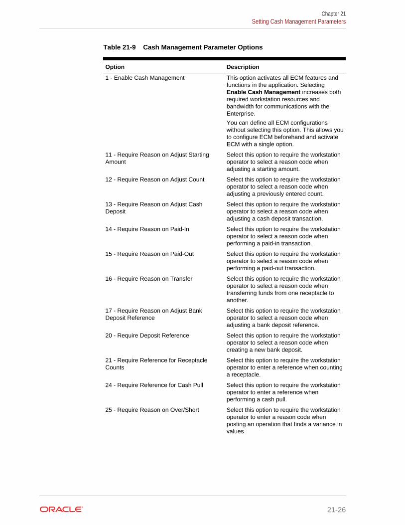
Table 21-9 Cash Management Parameter Options
Option Description
1 - Enable Cash Management This option activates all ECM features andfunctions in the application. SelectingEnable Cash Management increases bothrequired workstation resources andbandwidth for communications with theEnterprise.
You can define all ECM configurationswithout selecting this option. This allows youto configure ECM beforehand and activateECM with a single option.
11 - Require Reason on Adjust StartingAmount
Select this option to require the workstationoperator to select a reason code whenadjusting a starting amount.
12 - Require Reason on Adjust Count Select this option to require the workstationoperator to select a reason code whenadjusting a previously entered count.
13 - Require Reason on Adjust CashDeposit
Select this option to require the workstationoperator to select a reason code whenadjusting a cash deposit transaction.
14 - Require Reason on Paid-In Select this option to require the workstationoperator to select a reason code whenperforming a paid-in transaction.
15 - Require Reason on Paid-Out Select this option to require the workstationoperator to select a reason code whenperforming a paid-out transaction.
16 - Require Reason on Transfer Select this option to require the workstationoperator to select a reason code whentransferring funds from one receptacle toanother.
17 - Require Reason on Adjust BankDeposit Reference
Select this option to require the workstationoperator to select a reason code whenadjusting a bank deposit reference.
20 - Require Deposit Reference Select this option to require the workstationoperator to select a reason code whencreating a new bank deposit.
21 - Require Reference for ReceptacleCounts
Select this option to require the workstationoperator to enter a reference when countinga receptacle.
24 - Require Reference for Cash Pull Select this option to require the workstationoperator to enter a reference whenperforming a cash pull.
25 - Require Reason on Over/Short Select this option to require the workstationoperator to enter a reason code whenposting an operation that finds a variance invalues.
Chapter 21Setting Cash Management Parameters
21-26
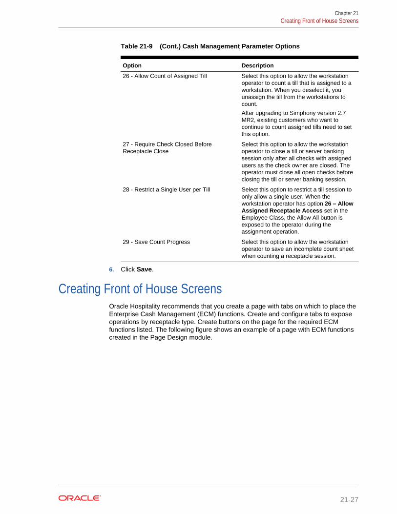
Table 21-9 (Cont.) Cash Management Parameter Options
Option Description
26 - Allow Count of Assigned Till Select this option to allow the workstationoperator to count a till that is assigned to aworkstation. When you deselect it, youunassign the till from the workstations tocount.
After upgrading to Simphony version 2.7MR2, existing customers who want tocontinue to count assigned tills need to setthis option.
27 - Require Check Closed BeforeReceptacle Close
Select this option to allow the workstationoperator to close a till or server bankingsession only after all checks with assignedusers as the check owner are closed. Theoperator must close all open checks beforeclosing the till or server banking session.
28 - Restrict a Single User per Till Select this option to restrict a till session toonly allow a single user. When theworkstation operator has option 26 – AllowAssigned Receptacle Access set in theEmployee Class, the Allow All button isexposed to the operator during theassignment operation.
29 - Save Count Progress Select this option to allow the workstationoperator to save an incomplete count sheetwhen counting a receptacle session.
6. Click Save.
Creating Front of House ScreensOracle Hospitality recommends that you create a page with tabs on which to place theEnterprise Cash Management (ECM) functions. Create and configure tabs to exposeoperations by receptacle type. Create buttons on the page for the required ECMfunctions listed. The following figure shows an example of a page with ECM functionscreated in the Page Design module.
Chapter 21Creating Front of House Screens
21-27

Figure 21-2 Front of House Screen in Page Design
1. Create tabs for Safe, Bank Deposit, Till, Server Bank, and General.
2. On each tab, create buttons for each of the functions listed in the following table.
Table 21-10 ECM Front of House Tabs and Buttons
Tab Button Name Function
Safe Add Funds Add money to the safe.
Adjust Count Correct values from theprevious count.
Change Count Sheet Adjust the count sheet thatworkstations operators useto perform a count.
Close Receptacle Close the safe’s trackingsession.
Count Receptacle Count the money in the safe.
Deposit Cash Deposit cash into the safe.
Open New Change OrderRequest
Open a Change Order whena safe is low on a particulardenomination or to stock upfor an event.
Open New Receptacle Open a new safe trackingsession.
Paid-In Accept funds for the safeoutside of a guest check.
Paid-Out Distribute funds from thesafe outside of a guestcheck.
Remove Funds Remove money from a safesession and from tracking.
Chapter 21Creating Front of House Screens
21-28

Table 21-10 (Cont.) ECM Front of House Tabs and Buttons
Tab Button Name Function
Transfer Funds Transfer money from thesafe to another receptacle.
Bank Deposit Adjust Bank DepositReference
Change the reference of abank deposit session.
Adjust Cash Deposit Change the amount of acash deposit that was placedinto the bank depositsession.
Open New Receptacle Open a new bank deposittracking session.
Reconcile Bank Deposit Close the bank deposit.
Transfer Funds Transfer money from thebank deposit to anotherreceptacle.
Till Adjust Count Correct values from theprevious count.
Adjust Till Starting Amount Change the starting amountof a till session after openingit.
Assign Till to Cash Drawer Assign a till to a cashdrawer.
Assign User(s) to Till Assign one or moreoperators to the till sessionon the workstation.
Change Count Sheet Adjust the count sheet thatworkstations operators useto perform a count.
Close Receptacle Close the till’s trackingsession.
Count Receptacle Count the money in the till.
Deposit Cash Deposit cash into the till.
Paid-In Accept funds for the tilloutside of a guest check.
Paid-Out Distribute funds from the tilloutside of a guest check.
Pull Cash Remove cash from the tillsession.
Quick Start Till Quickly assign a workstationoperator and till to a cashdrawer on the workstation.
Transfer Funds Transfer money from the tillto another receptacle.
Unassign Till from CashDrawer
Restrict the till to a limitednumber of operations. Thisfunction does not close thetill.
Chapter 21Creating Front of House Screens
21-29

Table 21-10 (Cont.) ECM Front of House Tabs and Buttons
Tab Button Name Function
Unassign User(s) from Till Prevent the workstationoperator from performingtransactions on the till. Thisfunction does not close thetill.
Server Bank Adjust Count Correct values from theprevious count.
Adjust Server Bank StartingAmount
Change the starting amountof a till session after openingit.
Close Receptacle Close the server bank’stracking session.
Count Receptacle Count the money in theserver bank.
Deposit Cash Deposit cash into the serverbank.
Paid-In Accept funds for the serverbank outside of a guestcheck.
Paid-Out Distribute funds from theserver bank outside of aguest check.
Pull Cash Remove cash from theserver bank session.
Transfer Funds Transfer money from theserver bank to anotherreceptacle.
General View Receptacle Status Look at summary informationfor all receptacle sessions.
Till Assignment Status(Smart Key)
Determine whether a till isassigned to a cash draweron the workstation.
Related Topics
• Configuring a Till Through Extensibility
Configuring a Smart Key on a WorkstationA smart key prevents the use of a workstation until you assign a till session to a cashdrawer on the workstation. After assignment, the key permits the workstation operatorto sign into the workstation. Follow these steps to implement the optional smart key.
1. In the EMC, select the Enterprise, zone, property, or revenue center, clickConfiguration and Page Design.
2. Select the Sign In Page.
3. On the Edit tab, click Button.
4. Enter information in the Page Design fields.
Chapter 21Configuring a Smart Key on a Workstation
21-30
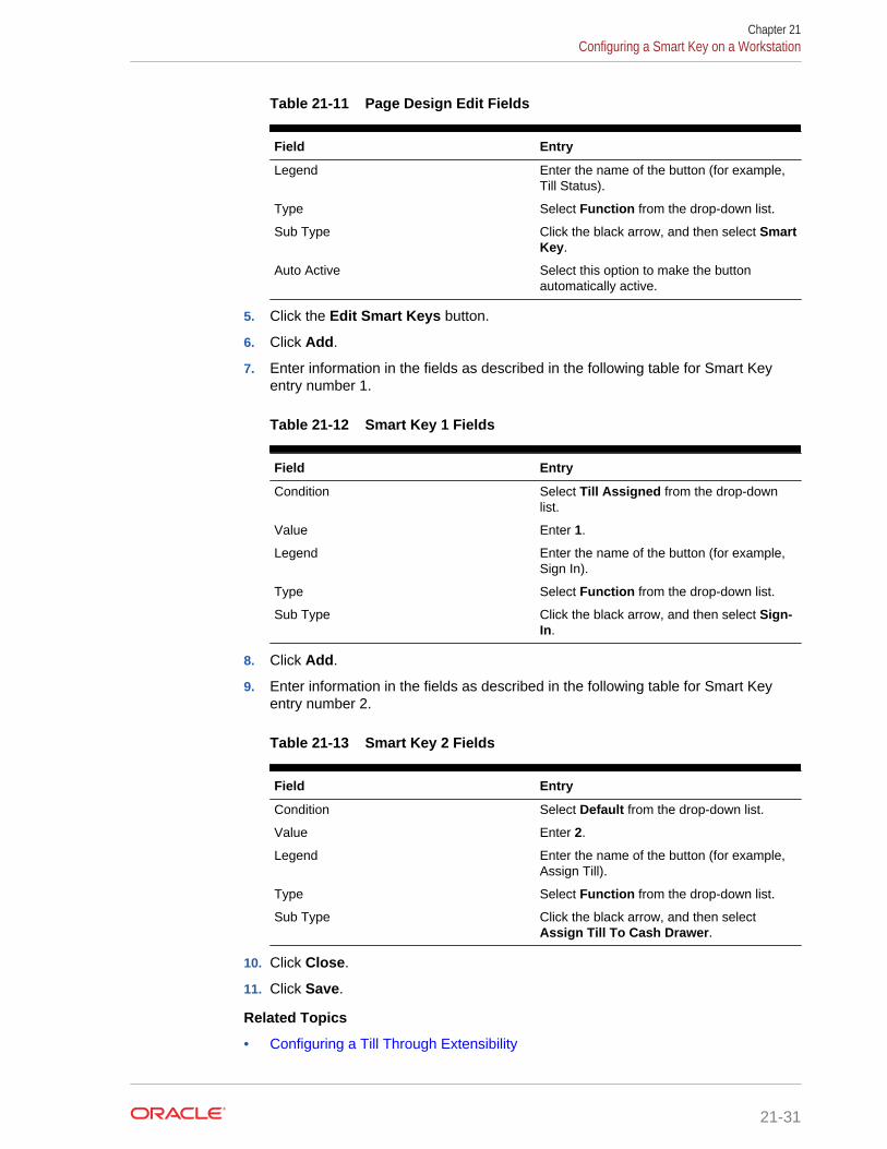
Table 21-11 Page Design Edit Fields
Field Entry
Legend Enter the name of the button (for example,Till Status).
Type Select Function from the drop-down list.
Sub Type Click the black arrow, and then select SmartKey.
Auto Active Select this option to make the buttonautomatically active.
5. Click the Edit Smart Keys button.
6. Click Add.
7. Enter information in the fields as described in the following table for Smart Keyentry number 1.
Table 21-12 Smart Key 1 Fields
Field Entry
Condition Select Till Assigned from the drop-downlist.
Value Enter 1.
Legend Enter the name of the button (for example,Sign In).
Type Select Function from the drop-down list.
Sub Type Click the black arrow, and then select Sign-In.
8. Click Add.
9. Enter information in the fields as described in the following table for Smart Keyentry number 2.
Table 21-13 Smart Key 2 Fields
Field Entry
Condition Select Default from the drop-down list.
Value Enter 2.
Legend Enter the name of the button (for example,Assign Till).
Type Select Function from the drop-down list.
Sub Type Click the black arrow, and then selectAssign Till To Cash Drawer.
10. Click Close.
11. Click Save.
Related Topics
• Configuring a Till Through Extensibility
Chapter 21Configuring a Smart Key on a Workstation
21-31

Configuring a Till Through ExtensibilityECM provides the Designate till number during assignment capability throughextensibility. When you set the InitiatingCommand.Arguments to a valid receptacleobject number, the application attempts to use that till when assigning a till to aworkstation. If the till is not found or is assigned to another workstation, the applicationprompts the workstation operator for the till to assign.
Related Topics
• Creating Front of House Screens
• Configuring a Smart Key on a Workstation
ECM ReportingEnterprise Cash Management (ECM) reporting for receptacles and activity is availableat the Enterprise and property hierarchy levels.
Related Topics
• Assigning Enterprise Reports
• Creating ECM Property Reports
ECM Enterprise ReportsEnterprise reports provide information about active and completed receptacle sessionsfor the Enterprise in Oracle Hospitality Reporting and Analytics, including the reportslisted in the following table. These reports contain drill-down options to allow simpleauditing for all receptacle tracking sessions related to the report.
Table 21-14 ECM Enterprise Reports
Report Contains Information About
Safe Report All safe sessions (regardless of their state) for the selectedlocation and business date
Petty Cash Report All petty cash sessions (regardless of their state) for theselected location and business date
Till Report All till sessions (regardless of their state) for the selectedlocation and business date
Bank Deposit Report All bank deposit sessions (regardless of their state) for theselected location and business date
Count Adjustment Report Count adjustments that were performed for any receptacletracking session for the selected properties
Starting Amount AdjustmentReport
Adjustments to starting amounts that were defined for anyreceptacle session for the selected location and businessdate
Over/Short Detail Report Over and short conditions that were reported for receptaclesession for the selected location and business date
Paid-In/Paid-Out Report Paid-in and paid-out transactions that were reported for anyreceptacle tracking sessions for the selected properties
Chapter 21Configuring a Till Through Extensibility
21-32
Table 21-14 (Cont.) ECM Enterprise Reports
Report Contains Information About
Activity Report All transactions and operations that were performed forreceptacle sessions. All transactions and operations arelisted chronologically, allowing an auditor to view an exactaccount of all activities performed from open to close for thereceptacle session.
Related Topics
• Assigning Enterprise Reports
• Creating ECM Property Reports
Assigning Enterprise ReportsEnterprise reports must be assigned to an employee role in Oracle HospitalityReporting and Analytics before authorized employees can run them. An administratortypically assigns the reports to a role.
1. In Reporting and Analytics, click Admin, Warehouse, Reports, and ReportRoles.
2. Highlight a role and click Select.
3. On the Role Reports screen, click Add.
4. Select the report names from the list and click Save.
5. Create a report category:
a. Click Admin, Warehouse, Reports, and Report Categories.
b. Click Add.
c. On the Report Categories screen, enter the Name of the new report category,a Description, and specify a Sort Order.
d. Click Save.
Related Topics
• ECM Reporting
• ECM Enterprise Reports
Creating ECM Property Reports
Property reporting at the workstation provides reports on active and completedreceptacle sessions. Create front of house buttons for each property report listed in thefollowing table. Workstation Touchscreen Pages contains more information aboutconfiguring front of house buttons.
Chapter 21Assigning Enterprise Reports
21-33

Table 21-15 Enterprise Cash Management (ECM) Property Reports
Report Contains Information About
Safes Report Active safe sessions for the location
Server Bank Report The active server bank session for theoperator logged in to the workstation
Server Banking Report Active server banking sessions for the location
Till Report Active till sessions assigned on theworkstation
Till Banking Report Active till sessions for the location
Cash Pull Report Cash pull transactions posted for the currentbusiness date
Over/Short Detail Report Over and short conditions recorded for thecurrent business date
Bank Deposit Report Active bank deposit sessions for the location
Petty Cash Report Active petty cash sessions for the location
Paid-In/Paid-Out Report Paid-in and paid-out transactions recorded forthe current business date
Related Topics
• ECM Reporting
• ECM Enterprise Reports
ECM Workstation HardwareThe following table lists the workstation hardware models and operating systemssupported for Enterprise Cash Management (ECM) receptacle operations andfunctions. Some functionality related to the operation of tills is limited with tablets,handhelds, and other mobile devices. These devices are indicated in the table with anasterisk (*).
The receptacle’s tracking session includes ECM tracked transactions that areprocessed as part of normal guest check operations, regardless of the hardwaremodel or supported operating system from which they originated.
Table 21-16 Workstation Hardware
Model Operating System ECM Features Supported?
Oracle MICROS Workstation 6 Windows 8.1 Yes
Oracle MICROS Tablet E-Series (8-inch and 11-inch)
Windows 8.1 Yes*
Oracle MICROS Workstation5a
Win32 Yes
Oracle MICROS PCWorkstation 2015
Win32 Yes
Oracle MICROS PCWorkstation 2010
Win32 Yes
Chapter 21ECM Workstation Hardware
21-34

Table 21-16 (Cont.) Workstation Hardware
Model Operating System ECM Features Supported?
DT Research 362 POSReady 7 Yes*
DT Research 365 Windows 7 Yes*
Zebra MC40 (formerly theMotorola MC40)
Android 4.1 Yes*
Apple iPad – All Models iOS 8 No
Certified Consumer Devices(Android)
Android 4.4 Yes*
Related Topics
• Enterprise Cash Management
• Tracking Tender Transaction Items
• Tracking Service Charge Transactions
• Tracking Discount Transactions
Enterprise Cash Management Configuration LevelsThe following table lists the hierarchy levels within the Enterprise ManagementConsole (EMC) that allow configuration of Enterprise Cash Management (ECM)operations.
Table 21-17 EMC Configuration Levels
EMCConfigurationName
Enterprise Property RVC Zone
Accounts X X X X
Cash CountThreshold Sets
X X X X
CashManagementClasses
X X X X
CashManagementParameters
X X X X
CashManagementReasons
X X X X
Cash PullThreshold Sets
X X X X
Count Sheets X X X X
EmployeeClasses
X
Chapter 21Enterprise Cash Management Configuration Levels
21-35
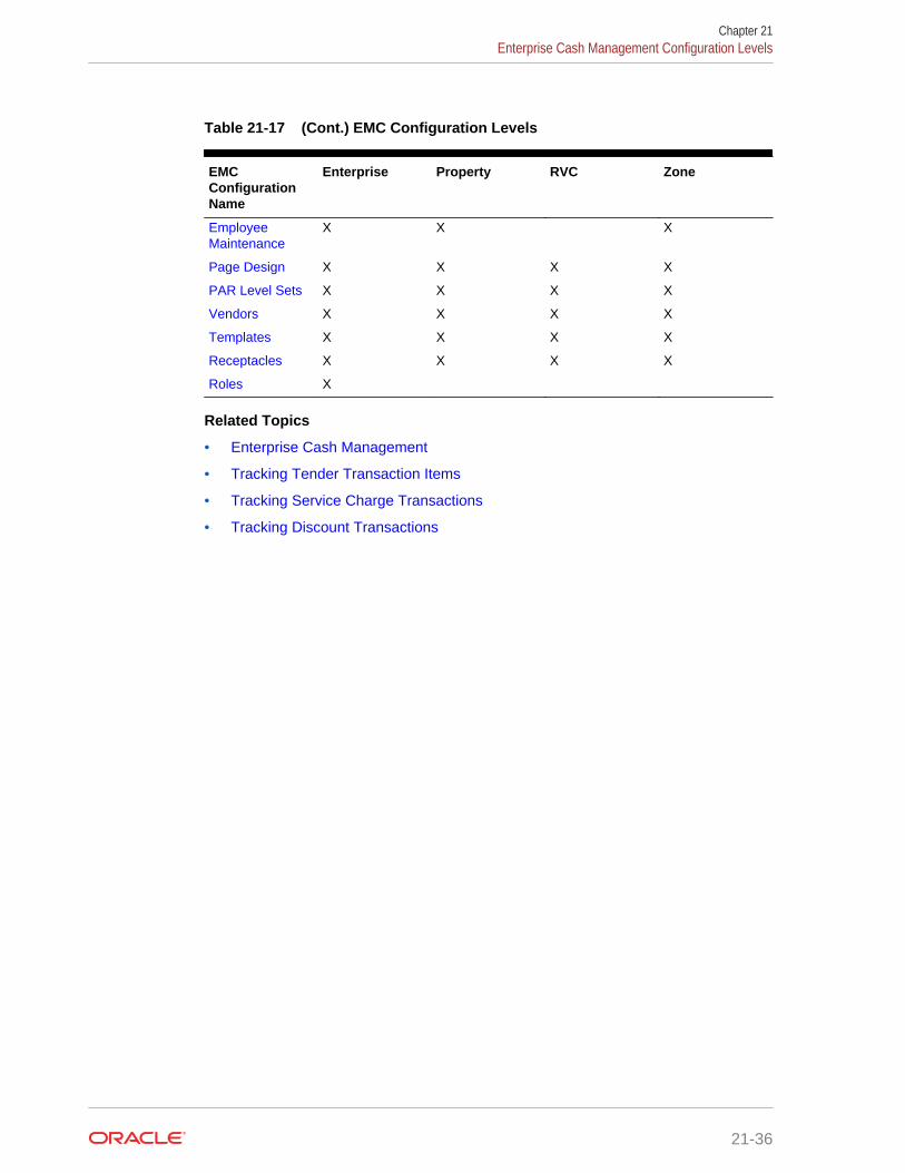
Table 21-17 (Cont.) EMC Configuration Levels
EMCConfigurationName
Enterprise Property RVC Zone
EmployeeMaintenance
X X X
Page Design X X X X
PAR Level Sets X X X X
Vendors X X X X
Templates X X X X
Receptacles X X X X
Roles X
Related Topics
• Enterprise Cash Management
• Tracking Tender Transaction Items
• Tracking Service Charge Transactions
• Tracking Discount Transactions
Chapter 21Enterprise Cash Management Configuration Levels
21-36
22Loyalty and Gift Card Interfaces andDrivers
Oracle Hospitality Gift and Loyalty is a customer relationship management (CRM)application that allows properties to manage point-based loyalty card programs andstored value cards (SVC) (also known as gift cards). Gift and Loyalty tracks customeractivities (such as frequency of visits, spending, and loyalty account balance) andreports the information through Simphony’s enterprise reporting module. Simphonythen sends this information to Gift and Loyalty.
The following table lists common types of loyalty programs:
Table 22-1 Types of Loyalty Programs
Loyalty Program Description
Points earned per transaction or pervisit
An award given for X number of visits. The award couldbe a discount, coupon for future visit, or stored valueadded to the loyalty account for later redemption.
Points earned per dollar spent An award given for X dollars spent. The award could bea discount, coupon for future visit, or stored valueadded to the loyalty account for later redemption.
Discount card Each time the workstation operator swipes a card, thecheck receives an automatic discount. Restaurantstypically use discount cards to control employee mealdiscounts.
Category club card The customer earns points when ordering a specifictype of menu item (for example, burgers).
A stored value program allows a guest to establish a prepaid account to use forpurchases at a property. The prepaid payment vehicle is a stored value card (SVC)with an associated monetary value. A gift card is an example of a stored value cardcontaining a prepaid amount.
• Loyalty and Stored Value Configuration Prerequisites
• Loyalty Configuration Tasks
• Configuring Loyalty and Stored Value Privileges
• Setting Loyalty Options
• Configuring the Loyalty Driver
• Configuring the Loyalty Module
• Stored Value Configuration Tasks
• Setting Stored Value Options
• Configuring the Stored Value Driver
• Configuring the Stored Value Module
22-1
• Creating Front of House Loyalty and Stored Value Buttons
• Voiding Points on a Re-opened Check
• XProcessor Extension Application Migration
Loyalty and Stored Value Configuration PrerequisitesSimphony supports the Gift and Loyalty drivers only on WinCE and Win32 operatingsystems.
Complete the following tasks before configuring the Loyalty and Stored ValueInterfaces and Drivers:
1. Install Simphony version 2.5 Maintenance Release (MR) 1 or later at the property.
2. Obtain access to the Enterprise Management Console (EMC) within Simphony.
3. Configure unique Tender/Media and Discount records for loyalty transactions.Take note of the record number and type as you need the values to posttransactions for Reporting and Analytics and third party loyalty applications.
Oracle Hospitality Reporting and Analytics and third party loyalty applications usethe configured Simphony Tender/Media and Discount records to post loyaltytransactions to the guest check.
4. (Optional) If the site is using the XProcessor Extension Application for Gift andLoyalty, configure the Gift and Loyalty interface and XProcessor ExtensionApplication at the Enterprise level. Deploy each interface only to the correctlocations and clients. After you upgrade the appropriate clients to Simphonyversion 2.5 MR1 or later, see XProcessor Extension Application Migration forinstructions.
a. Leave the XProcessor installed at the Enterprise level until all clients havebeen upgraded to Simphony version 2.5 MR1 or later and are using the Giftand Loyalty interface.
b. Retrieve the data extension overrides for each property (such as uniformresource locator (URL), userid, user_password, and timeout_seconds). Takenote of these settings as you need this information to create the integrated Giftand Loyalty interface.
c. Take note of the current functions the site uses through XProcessor. You needthis information to create buttons for the Gift and Loyalty interface.
5. (Optional) If a third party developed a driver, use the driver configuration settingsprovided by the third party. Third party drivers may have unique fields.
Related Topics
• Loyalty Configuration Tasks
Loyalty Configuration TasksComplete the following tasks to set up the loyalty interface:
• Carry out the configuration prerequisites
• Configure loyalty privileges
• Set loyalty options
Chapter 22Loyalty and Stored Value Configuration Prerequisites
22-2
• Configure the Loyalty driver
• Configure the Loyalty module
• Create Front of House loyalty buttons
• Allow workstation operators to void loyalty points issued on re-opened checks
• (If applicable) Migrate the XProcessor Extension Application
Related Topics
• Loyalty and Stored Value Configuration Prerequisites
• Configuring Loyalty and Stored Value Privileges
• Setting Loyalty Options
• Configuring the Loyalty Driver
• Configuring the Loyalty Module
• Creating Front of House Loyalty and Stored Value Buttons
• Voiding Points on a Re-opened Check
• XProcessor Extension Application Migration
Configuring Loyalty and Stored Value Privileges1. In the EMC, select the Enterprise level, click Configuration and Roles.
2. Select the role type, click Operations and Stored Value Cards.
3. Select the appropriate options for the privileges. The following table summarizesthe privileges associated with Loyalty and Stored Value functionality.
Table 22-2 Loyalty and Stored Value Privileges
Section Option Number Privilege Name Select This Option toAllow Employees to...
Issue Functions 104 Authorize/Perform IssueStored Value Function
Issue a stored valuecard.
Issue Functions 105 Authorize/Perform VoidIssue Stored ValueEntry
Void an issued card.
Issue Functions 106 Authorize/Perform IssueStored Value BatchFunction
Issue a batch of storedvalue cards.
Issue Functions 107 Authorize/Perform VoidIssue Stored ValueBatch Entry
Void a batch of storedvalue cards.
Issue Functions 108 Authorize/PerformActivate Stored ValueFunction
Activate a stored valuecard.
Issue Functions 109 Authorize/Perform VoidActivate Stored ValueEntry
Void the activation of astored value card.
Chapter 22Configuring Loyalty and Stored Value Privileges
22-3

Table 22-2 (Cont.) Loyalty and Stored Value Privileges
Section Option Number Privilege Name Select This Option toAllow Employees to...
Issue Functions 110 Authorize/PerformActivate Stored ValueBatch Function
Activate a batch ofstored value cards.
Issue Functions 111 Authorize/Perform VoidActivate Stored ValueBatch Entry
Void the activation of abatch of stored valuecards.
Reload andRedeem Functions
112 Authorize/PerformReload Stored ValueFunction
Reload (add credit) adollar amount to anexisting stored valuecard.
Reload andRedeem Functions
113 Authorize/Perform VoidReload Stored ValueEntry
Void a reloadtransaction.
Reload andRedeem Functions
114 Authorize/PerformRedeem AuthorizationStored Value Function
Perform a redemptionauthorization.
Reload andRedeem Functions
115 Authorize/Perform VoidRedeem AuthorizationStored Value Entry
Void a redemptionauthorization.
Reload andRedeem Functions
116 Authorize/PerformRedeem Stored ValueFunction
Perform a redemptiontransaction (a customermakes a purchase usinga stored value card, andthe application deducts adollar amount from thecustomer’s account).
Reload andRedeem Functions
117 Authorize/Perform VoidRedeem Stored ValueEntry
Void a redemptiontransaction.
Reload andRedeem Functions
118 Authorize/PerformManual RedemptionStored Value Function
Perform a manualredemption.
Reload andRedeem Functions
119 Authorize/Perform VoidManual RedemptionStored Value Entry
Void a manualredemption transaction.
Point Functions 120 Authorize/Perform IssueStored Value PointsFunction
Issue points to a storedvalue card.
Point Functions 121 Authorize/Perform VoidIssue Stored ValuePoints Entry
Void the issued pointson a stored value card.
Point Functions 122 Authorize/PerformRedeem Stored ValuePoints Function
Perform a pointsredemption transaction.
Point Functions 123 Authorize/Perform VoidRedeem Stored ValuePoints Entry
Void a points redemptiontransaction.
Chapter 22Configuring Loyalty and Stored Value Privileges
22-4

Table 22-2 (Cont.) Loyalty and Stored Value Privileges
Section Option Number Privilege Name Select This Option toAllow Employees to...
Other StoredValue CardOptions
103 Authorize/PerformManual Entry of StoredValue Card Number
Manually enter thestored value cardaccount number.
Other StoredValue CardOptions
124 Authorize/PerformStored Value Cash OutFunction
Debit some or all of theremaining balance on astored value card.
Other StoredValue CardOptions
179 Authorize/Perform VoidStored Value Cash OutFunction
Void a cash outtransaction.
Other StoredValue CardOptions
125 Authorize/PerformStored Value BalanceInquiry Function
Check a stored valuecard balance.
Other StoredValue CardOptions
126 Authorize/PerformStored Value BalanceTransfer Function
Transfer the balancefrom one stored valuecard to another.
Other StoredValue CardOptions
127 Authorize/PerformStored Value PointInquiry Function
Check a stored valuecard point balance.
Other StoredValue CardOptions
128 Authorize/PerformStored Value ReportGeneration Function
Generate stored valuecard reports.
Loyalty Options 166 Authorize/PerformLoyalty Coupon Inquiry
Request a list ofcoupons that areavailable for a loyaltyaccount.
Loyalty Options 167 Authorize/PerformAccept Loyalty CouponFunction
Redeem a couponassociated with a loyaltyaccount.
Loyalty Operations 168 Authorize/Perform VoidAccept Loyalty CouponEntry
Void the couponredemption.
Loyalty Operations 169 Authorize/Perform IssueLoyalty CouponFunction
Issue a coupon to aloyalty account.
Loyalty Operations 170 Authorize/Perform IssueLoyalty Points Function
Issue points to a loyaltyaccount.
Loyalty Operations 171 Authorize/Perform VoidIssue Loyalty PointsEntry
Void the point issuance.
Loyalty Operations 172 Authorize/PerformRedeem Loyalty PointsFunction
Accept or redeem pointsto apply towards thebalance of a check.
Loyalty Operations 173 Authorize/Perform VoidRedeem Loyalty PointsEntry
Void the pointsredemption.
Loyalty Operations 174 Authorize/PerformRedeem and IssueLoyalty Points Function
Redeem points andissue additional points toa loyalty account.
Chapter 22Configuring Loyalty and Stored Value Privileges
22-5
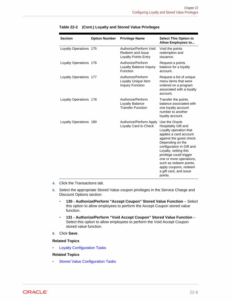
Table 22-2 (Cont.) Loyalty and Stored Value Privileges
Section Option Number Privilege Name Select This Option toAllow Employees to...
Loyalty Operations 175 Authorize/Perform VoidRedeem and IssueLoyalty Points Entry
Void the pointsredemption andissuance.
Loyalty Operations 176 Authorize/PerformLoyalty Balance InquiryFunction
Request a pointsbalance for a loyaltyaccount.
Loyalty Operations 177 Authorize/PerformLoyalty Unique ItemInquiry Function
Request a list of uniquemenu items that wereordered on a programassociated with a loyaltyaccount.
Loyalty Operations 178 Authorize/PerformLoyalty BalanceTransfer Function
Transfer the pointsbalance associated withone loyalty accountnumber to anotherloyalty account.
Loyalty Operations 180 Authorize/Perform ApplyLoyalty Card to Check
Use the OracleHospitality Gift andLoyalty operation thatapplies a card accountagainst the guest check.Depending on theconfiguration in Gift andLoyalty, setting thisprivilege could triggerone or more operations,such as redeem points,apply coupons, redeema gift card, and issuepoints.
4. Click the Transactions tab.
5. Select the appropriate Stored Value coupon privileges in the Service Charge andDiscount Options section:
• 130 - Authorize/Perform “Accept Coupon” Stored Value Function – Selectthis option to allow employees to perform the Accept Coupon stored valuefunction.
• 131 - Authorize/Perform “Void Accept Coupon” Stored Value Function –Select this option to allow employees to perform the Void Accept Couponstored value function.
6. Click Save.
Related Topics
• Loyalty Configuration Tasks
Related Topics
• Stored Value Configuration Tasks
Chapter 22Configuring Loyalty and Stored Value Privileges
22-6

Setting Loyalty Options1. In the EMC, select the Enterprise, property, or revenue center, click
Configuration and Loyalty.
2. Insert a record and enter Loyalty as the name.
3. Double-click the record to open it.
4. Select the appropriate Loyalty Options as described in the following table.
Table 22-3 Loyalty Options
Option Description
Support Offline Transactions Select this option to allow offline loyalty transactions.
Always Print Loyalty Results Select this option to have a chit print automaticallyafter each successful loyalty operation.
Never Display Loyalty Results Select this option to require the workstation operatorto touch the workstation in order to show loyaltyresults.
Remove Loyalty Results PrintButton
Select this option if you do not want a Print button toappear on the loyalty results screen. Select thisoption in conjunction with the Always Print LoyaltyResults option.
Remove Guest Name LookupButton
Select this option if you do not want the Guest NameLookup button to appear on the account numberentry screen. This option deactivates the GuestName Lookup function.
Remove Phone Number LookupButton
Select this option if you do not want the PhoneNumber Lookup button to appear on the accountnumber entry screen. This option deactivates thePhone Number Lookup function.
5. Click Save.
Related Topics
• Loyalty Configuration Tasks
Configuring the Loyalty Driver1. In the EMC, select the Enterprise, property, or revenue center, click Setup and
Loyalty Driver.
2. Insert a record and enter an appropriate gift and loyalty driver name.
3. Double-click the record to open it.
4. On the General tab, click the Import from a file link.
5. Browse to C:\MICROS\Simphony2\EgatewayService\handlers, selectLoyaltyCommandModule.dll, and click Open.
6. Select the Configuration tab.
7. In the Assembly/Class section, enter information in the following fields:
Chapter 22Setting Loyalty Options
22-7
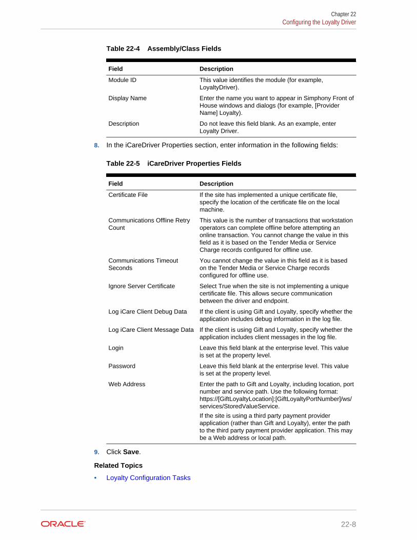
Table 22-4 Assembly/Class Fields
Field Description
Module ID This value identifies the module (for example,LoyaltyDriver).
Display Name Enter the name you want to appear in Simphony Front ofHouse windows and dialogs (for example, [ProviderName] Loyalty).
Description Do not leave this field blank. As an example, enterLoyalty Driver.
8. In the iCareDriver Properties section, enter information in the following fields:
Table 22-5 iCareDriver Properties Fields
Field Description
Certificate File If the site has implemented a unique certificate file,specify the location of the certificate file on the localmachine.
Communications Offline RetryCount
This value is the number of transactions that workstationoperators can complete offline before attempting anonline transaction. You cannot change the value in thisfield as it is based on the Tender Media or ServiceCharge records configured for offline use.
Communications TimeoutSeconds
You cannot change the value in this field as it is basedon the Tender Media or Service Charge recordsconfigured for offline use.
Ignore Server Certificate Select True when the site is not implementing a uniquecertificate file. This allows secure communicationbetween the driver and endpoint.
Log iCare Client Debug Data If the client is using Gift and Loyalty, specify whether theapplication includes debug information in the log file.
Log iCare Client Message Data If the client is using Gift and Loyalty, specify whether theapplication includes client messages in the log file.
Login Leave this field blank at the enterprise level. This valueis set at the property level.
Password Leave this field blank at the enterprise level. This valueis set at the property level.
Web Address Enter the path to Gift and Loyalty, including location, portnumber and service path. Use the following format:https://[GiftLoyaltyLocation]:[GiftLoyaltyPortNumber]/ws/services/StoredValueService.
If the site is using a third party payment providerapplication (rather than Gift and Loyalty), enter the pathto the third party payment provider application. This maybe a Web address or local path.
9. Click Save.
Related Topics
• Loyalty Configuration Tasks
Chapter 22Configuring the Loyalty Driver
22-8

Configuring the Loyalty Module1. In the EMC, select the Enterprise, property, or revenue center, click Setup and
Loyalty Module.
2. Insert a record and enter LoyaltyModule as the name.
3. Double-click the record to open it.
4. On the General tab, click the Import from a file link.
5. Browse to C:\MICROS\Simphony2\EgatewayService\handlers, selectLoyaltyCommandModule.dll, and click Open.
6. Click the Configuration tab.
7. In the Assembly/Class section, enter information in the following fields:
• Module ID – This value identifies the module.
• Display Name – Enter the name you want to appear in Simphony Front ofHouse windows and dialogs (for example, [Provider Name] Loyalty).
• Description – Enter a description of the loyalty module. Do not leave this fieldblank.
8. In the Common Properties section, enter information in the following fields:
• Currency ISO Code – Enter the code (3 alpha characters) that represents thecurrency being used (for example, USD).
See http://www.currency-iso.org/en/home/tables/table-a1.html for a list ofCurrency ISO 4217 codes.
• Language ISO Code – Enter the code (2 alpha characters) that representsthe language being used (for example, EN).
See http://www.loc.gov/standards/iso639-2/php/code_list.php for a list ofLanguage ISO 639–1 codes.
If the currency or language is different at the property, override these values at theproperty level.
9. In the Loyalty Module Properties section, enter information in the following fields:
• Account Number Maximum Length – Enter the maximum length of a loyaltyaccount number (up to 24 digits).
• Account Number Minimum Length – Enter the minimum length of a loyaltyaccount number (down to 7 digits).
• Cash Module Name – Enter the name of the cash module to use forredemptions (for example, Cash:Cash).
10. Click Save.
11. Select the property, click Setup and Loyalty Driver.
12. Double-click the gift and loyalty driver record to open it.
13. Click the Override This Record link, and then click Yes to confirm.
14. Click the Configuration tab.
15. In the iCare Driver Properties section, enter information in the following fields:
Chapter 22Configuring the Loyalty Module
22-9

• Login – Enter the login for the property ID or the login for the provider.
• Password – Enter the password for the property ID or the provider.
16. Click Save.
Related Topics
• Loyalty Configuration Tasks
Stored Value Configuration TasksComplete the following tasks to set up the stored value interface:
• Carry out the configuration prerequisites
• Configure stored value privileges
• Set stored value options
• Configure the Stored Value driver
• Configure the Stored Value module
• Create Front of House stored value buttons
• Allow workstation operators to void loyalty points issued on re-opened checks
• (If applicable) Migrate the XProcessor Extension Application
Related Topics
• Configuring Loyalty and Stored Value Privileges
• Setting Stored Value Options
• Configuring the Stored Value Driver
• Configuring the Stored Value Module
• Creating Front of House Loyalty and Stored Value Buttons
• XProcessor Extension Application Migration
Setting Stored Value Options1. In the EMC, select the Enterprise, property, or revenue center, click
Configuration and Stored Value.
2. Insert a record and enter Stored Value as the name.
3. Double-click the record to open it.
4. Select the appropriate Stored Value Options. The following table describes theoptions.
Table 22-6 Stored Value Options
Option Description
Support Offline Transactions Select this option to allow offline storedvalue transactions.
Chapter 22Stored Value Configuration Tasks
22-10
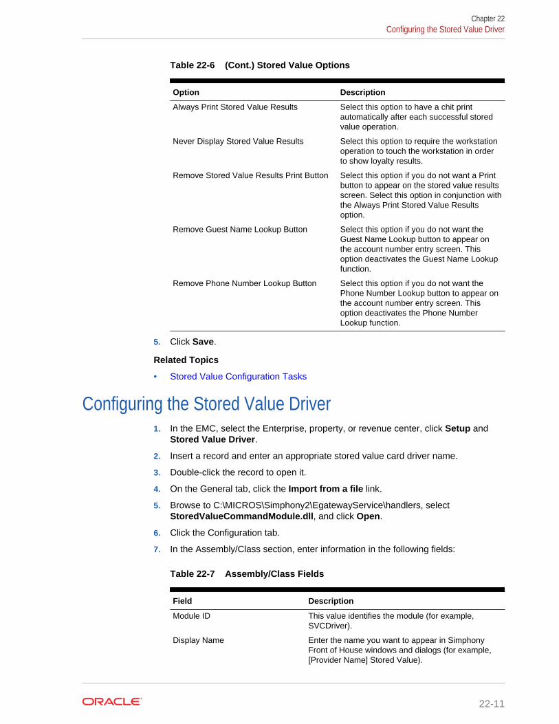
Table 22-6 (Cont.) Stored Value Options
Option Description
Always Print Stored Value Results Select this option to have a chit printautomatically after each successful storedvalue operation.
Never Display Stored Value Results Select this option to require the workstationoperation to touch the workstation in orderto show loyalty results.
Remove Stored Value Results Print Button Select this option if you do not want a Printbutton to appear on the stored value resultsscreen. Select this option in conjunction withthe Always Print Stored Value Resultsoption.
Remove Guest Name Lookup Button Select this option if you do not want theGuest Name Lookup button to appear onthe account number entry screen. Thisoption deactivates the Guest Name Lookupfunction.
Remove Phone Number Lookup Button Select this option if you do not want thePhone Number Lookup button to appear onthe account number entry screen. Thisoption deactivates the Phone NumberLookup function.
5. Click Save.
Related Topics
• Stored Value Configuration Tasks
Configuring the Stored Value Driver1. In the EMC, select the Enterprise, property, or revenue center, click Setup and
Stored Value Driver.
2. Insert a record and enter an appropriate stored value card driver name.
3. Double-click the record to open it.
4. On the General tab, click the Import from a file link.
5. Browse to C:\MICROS\Simphony2\EgatewayService\handlers, selectStoredValueCommandModule.dll, and click Open.
6. Click the Configuration tab.
7. In the Assembly/Class section, enter information in the following fields:
Table 22-7 Assembly/Class Fields
Field Description
Module ID This value identifies the module (for example,SVCDriver).
Display Name Enter the name you want to appear in SimphonyFront of House windows and dialogs (for example,[Provider Name] Stored Value).
Chapter 22Configuring the Stored Value Driver
22-11

Table 22-7 (Cont.) Assembly/Class Fields
Field Description
Description Do not leave this field blank. As an example, enterSVC Driver.
8. In the iCareDriver Properties section, enter information in the following fields:
Table 22-8 iCareDriver Properties Fields
Field Description
Certificate File If the site has implemented a unique certificate file,specify the location of the certificate file on the localmachine.
Communications Offline RetryCount
This value is the number of transactions thatworkstation operators can complete offline beforeattempting an online transaction. You cannot changethe value in this field as it is based on the TenderMedia or Service Charge records configured foroffline use.
Communications Timeout Seconds You cannot change the value in this field as it isbased on the Tender Media or Service Chargerecords configured for offline use.
Ignore Server Certificate Select True when the site is not implementing aunique certificate file. This allows securecommunication between the driver and endpoint.
Log iCare Client Debug Data If the client is using Gift and Loyalty, specify whetherthe application includes debug information in the logfile.
Log iCare Client Message Data If the client is using Gift and Loyalty, specify whetherthe application includes client messages in the logfile.
Login Leave this field blank at the enterprise level. Thisvalue is set at the property level.
Password Leave this field blank at the enterprise level. Thisvalue is set at the property level.
Web Address Enter the path to Gift and Loyalty, including location,port number and service path. Use the followingformat: https:// [GiftLoyaltyLocation]:[GiftLoyaltyPortNumber]/ws/services/StoredValueService.
If the site is using a third party payment providerapplication (rather than Gift and Loyalty), enter thepath to the third party payment provider application.This may be a Web address or local path.
9. Click Save.
Related Topics
• Stored Value Configuration Tasks
Chapter 22Configuring the Stored Value Driver
22-12

Configuring the Stored Value Module1. In the EMC, select the Enterprise, property, or revenue center, click Setup and
Stored Value Module.
2. Insert a record and enter SVCModule as the name.
3. Double-click the record to open it.
4. On the General tab, click the Import from a file link.
5. Browse to C:\MICROS\Simphony2\EgatewayService\handlers, selectStoredValueCommandModule.dll, and click Open.
6. Click the Configuration tab.
7. In the Assembly/Class section, enter information in the following fields:
• Module ID – This value identifies the module.
• Display Name – Enter the name you want to appear in Simphony Front ofHouse windows and dialogs.
• Description – Enter a description of the stored value module. Do not leavethis field blank.
8. In the Common Properties section, enter information in the following fields:
• Currency ISO Code – Enter the code (3 alpha characters) that represents thecurrency being used (for example, USD).
See www.currency-iso.org/en/home/tables/table-a1.html for a list of CurrencyISO 4217 codes.
• Language ISO Code – Enter the code (2 alpha characters) that representsthe language being used (for example, EN).
See www.loc.gov/standards/iso639-2/php/code_list.php for a list of LanguageISO 639–1 codes.
If the currency or language is different at the property, override these values at theproperty level.
9. In the Stored Value Module Properties section, enter information in the followingfields:
• Account Number Maximum Length – Enter the maximum length of a storedvalue account number (up to 24 digits).
• Account Number Minimum Length – Enter the minimum length of a storedvalue account number (down to 7 digits).
• Cash Module Name – Enter the name of the cash module to use forredemptions (for example, Cash:Cash).
• Max Card Activation Quantity – Enter the maximum number of stored valuecards that can be activated with the Activate Multiple card operation.
• Max Card Issue Quantity
– Enter the maximum number of stored value cards that can be issued withthe Activate Multiple card operation.
10. Click Save.
Chapter 22Configuring the Stored Value Module
22-13
11. Select the property, click Setup and Stored Value Driver.
12. Double-click the stored value card driver record to open it.
13. Click the Override This Record link, and then click Yes to confirm.
14. Click the Configuration tab.
15. In the iCare Driver Properties section, enter information in the following fields:
• Login – Enter the login for the property ID or the login for the provider.
• Password – Enter the password for the property ID or the provider.
16. Click Save.
Related Topics
• Stored Value Configuration Tasks
Creating Front of House Loyalty and Stored Value ButtonsYou can create buttons on a page for the loyalty and stored value functions.
1. In the EMC, select the Enterprise, property, or revenue center, clickConfiguration and Page Design.
2. Open the Front of House page on which to place loyalty and stored value buttons.
3. On the Edit tab, select the page area in which to define the loyalty and storedvalue functions (typically the payment or function area).
4. Click Button.
5. On the General sub-tab, select the appropriate function from the Type drop-down.
• Loyalty Function
• Stored Value Function
6. Click the black arrow beneath the Type drop-down.
7. Select either iCare Loyalty or iCare Stored Value, and click OK.
8. On the Loyalty or Stored Value Operation Selection dialog, select the appropriateModule Type (iCareLoyaltyModule or iCareSVCModule), select the appropriatefunction in the Functions drop-down, and click OK.
9. Position and size the button on the page. Use the Style arrow to change the color.
10. In the Legend field, enter the button name and click Save. The following tables listthe loyalty and stored value button names and functions.
Buttons marked with an asterisk (*) are only available with Gift and Loyalty; thesefunctions are not available with third party payment providers. Do not use the LookUp Patron operation as it is not functional alone. Instead, see Setting LoyaltyOptions for information about lookup methods.
Table 22-9 Loyalty Buttons
Button Name Function
Balance Inquiry Request a points balance for a loyalty account.
Chapter 22Creating Front of House Loyalty and Stored Value Buttons
22-14

Table 22-9 (Cont.) Loyalty Buttons
Button Name Function
Unique Items Inquiry* Request a list of unique menu items that have been orderedon a program associated with a loyalty account.
Issue Points Issue points to a loyalty account.
Coupon Inquiry Request a list of coupons that are available for a loyaltyaccount.
Redeem Coupon Redeem a coupon to apply towards the balance of a guestcheck.
Issue Coupon Issue an ad hoc coupon from Gift and Loyalty to a guestloyalty account.
Transfer Loyalty Account Transfer the points balance and customer personalinformation associated with one loyalty account number toanother loyalty account.
Apply Card to Check* The Apply Card to Check function sends an Apply request toGift and Loyalty for the account number. Based upon Giftand Loyalty configuration, the workstation operator canselect the following actions:• Apply Coupon• Redeem Points• Redeem Stored Value Card (SVC)• Apply Coupon and Redeem SVC• Issue Points
The Apply Card to Check function requires a specialconfiguration to share data between the Loyalty and StoredValue modules. To configure the Apply Card to Checkbutton, on the General tab in the Text field, enter theSVCModule Name and Record Number. Use the formatSVCModuleName:RecordNumber to process SVC actionsassociated with this function. You can find the RecordNumber and Module Name in EMC by highlighting theenterprise, selecting Setup, and then selecting Stored ValueModule.
A property can load more than one type of loyalty module,although Oracle does not recommend doing so. If theproperty uses multiple loyalty modules, manually enter themodule name in the Arguments field for the second module.
Table 22-10 Stored Value Buttons
Button Name Function
Balance Inquiry Request the current monetary value for a stored valueaccount or gift card.
Issue SVC Issue one stored value account number for a dollar valuethat is determined at the time of purchase.
Issue Multiple SVCs* Issue multiple stored value account numbers for a dollarvalue that is determined at the time of purchase.
Activate SVC Activate one stored value account. The application promptsthe workstation operator to enter the pre-defined dollar valuefor validation.
Chapter 22Creating Front of House Loyalty and Stored Value Buttons
22-15

Table 22-10 (Cont.) Stored Value Buttons
Button Name Function
Activate Multiple SVCs* Activate multiple stored value account numbers for a dollarvalue that is determined at the time of purchase. Theapplication prompts the workstation operator to enter the pre-defined dollar value for validation.
Reload Add funds to an existing stored value account.
Transfer Transfer the funds and customer personal information (ifapplicable) associated with one stored value account toanother stored value account.
Authorize Authorize a gift card for use as payment on a guest check.
Redeem Pay a guest check balance using a gift card.
Cash Out Obtain a cash payment for any remaining balance on astored value account.
Redeem SVC/Issue Points* The Redeem SVC/Issue Points function combines theRedeem SVC and Loyalty Issue Points functions. Theapplication prompts the workstation operator to redeem a giftcard, and then automatically issues points.
The Redeem SVC/Issue Points function requires a specialconfiguration to share data between the Loyalty and StoredValue modules. To configure the Redeem SVC/Issue Pointsbutton, on the General tab in the Text field, enter theLoyaltyModule Name and Record Number. Use the formatLoyaltyModuleName:RecordNumber to process loyaltyactions associated with this function. You can find theRecord Number and Module Name in EMC by highlightingthe Enterprise level, clicking Setup and Loyalty Module.
A property can load more than one type of stored valuemodule, although Oracle does not recommend doing so. Ifthe property uses multiple stored value modules, manuallyenter the module name in the Arguments field for the secondmodule.
11. Repeat the preceding steps to create buttons for each of the loyalty and storedvalue functions listed in the tables.
Related Topics
• Loyalty Configuration Tasks
Related Topics
• Stored Value Configuration Tasks
Voiding Points on a Re-opened CheckTo allow workstation operators to void loyalty points issued on re-opened guestchecks, the check number must remain the same after reopening a check. By default,a guest check number increments each time a workstation operator re-opens thecheck, preventing the voiding of points due to check numbering mismatch.
1. In the EMC, select the revenue center, click RVC Parameters and Options.
2. Select 37 - Keep The Same Check Number When a Check is Reopened. Thisallows a re-opened guest check to retain its original guest check number. When
Chapter 22Voiding Points on a Re-opened Check
22-16

you deselect this option, Simphony assigns a re-opened guest check to a newcheck number.
3. Click Save.
Related Topics
• Loyalty Configuration Tasks
XProcessor Extension Application MigrationBeginning with Simphony version 2.5 MR1, properties can install the Loyalty driver forGift and Loyalty Advanced (in place of the XProcessor Extension Application). Youmust upgrade the appropriate clients to Simphony version 2.5 MR1 or later beforecompleting the steps in this section.
1. Browse to the Client Application Loader (CAL) server’s Win32 or WinCE sub-directory for Gift and Loyalty Advanced:
• CAL\Win32\ICareProcessor2.0 directory
• CAL\WinCE\ICareProcessor2.0 directory
2. Delete the ICareProcessor2.0 directory.
3. In the EMC, select the Enterprise level, click Setup and CAL Packages.
4. Delete the CAL Client package that was used to deploy the ICareProcessor2.0directory to the workstation(s).
5. Delete the following files from the disk:
• Micros.XProcessor.dll
• Micros.XProcessor.SVC.dll
• Micros.XProcessor.SVC.ICare.dll
6. Select the Enterprise, property, or revenue center, click Setup and ExtensionApplication.
7. Delete the Extension Application for XProcessor.
8. Select the Enterprise, property, or revenue center, click Setup and Payments.
9. Delete the XProcessor Payment driver.
10. Select the Enterprise or property, click Configuration and Tender/Media.
11. Delete XProcessor Close Check.
12. Delete the iCareSvcProcessor.icare.xml file.
13. Select the Enterprise level, click Configuration and Data Extensions.
14. Delete the data extensions for each property.
15. Select the Enterprise, property, or revenue center, click Configuration and PageDesign.
16. Double-click the page record containing Gift and Loyalty buttons to open it.
17. Delete all Gift and Loyalty buttons.
Depending on the property’s Gift and Loyalty configuration, additional menu items,discounts, service charges, or tenders may have been used. If these items are inuse, leave these additional items and do not delete them.
Chapter 22XProcessor Extension Application Migration
22-17

18. If the property was using the Check Reprocessor service, remove the installedcheck reprocessor files from the enterprise service host as the Gift and Loyaltyinterface has its own plug-ins.
19. Browse to the Handlers directory where the Check Reprocessor ran and open theChkReprocSvcHost.DLL.config file.
20. Delete the following tag:
<pluginAssembly displayname=”XProcessor Reprocessor”
fullname=”Micros.XProcessor.SVC.dll, Version=0.0.0.0, Culture=neutral,
PublicKeyToken=null” />
Leave the tags <pluginAssemblies> and </pluginAssemblies>.
21. Delete the following files from the Handlers directory:
• Micros.XProcessor.Payment.dll
• Micros.Ops.Extensibility.dll
• Micros.XProcessor.dll
• Micros.XProcessor.SVC.dll
• Micros.XProcessor.SVC.iCare.dll
Related Topics
• Loyalty Configuration Tasks
Related Topics
• Stored Value Configuration Tasks
Chapter 22XProcessor Extension Application Migration
22-18

23Setting Up the Web Service
A web service allows communication between Simphony and third party solutions.
• Understanding Transaction Services
• Configuring the Transaction Services Workstation Client
• Configuring the Transaction Services Employee
Understanding Transaction ServicesTransaction Services is a web service that allows Simphony to interface with thirdparty applications (for example, hotel self-service kiosks or room service devices,menu boards, and Enterprise online ordering). Transaction Services is commonlyinstalled in stadiums that use self-ordering devices. Guests can place orders using athird party application that interfaces with a Transaction Services client. The client thensends the guest checks to Simphony.
Related Topics
• Configuring the Transaction Services Workstation Client
• Configuring the Transaction Services Employee
Configuring the Transaction Services Workstation ClientYou can configure Transaction Services to run on the same hardware device as aSimphony client. Kiosks are usually configured as Transaction Services clients. Obtainthe following information before you begin the configuration:
• Transaction Services workstation name
• Number of revenue centers using Transaction Services
1. In the EMC, select the property, click Setup and Workstations.
2. Insert a record and enter the workstation name.
3. Double-click the workstation record.
4. In the Type field, select 3 - POSAPI Client.
5. Select the Service Host ID where the workstation will run.
6. In theAddress / Host Name field, enter the machine where Transaction Servicesis installed.
7. Click the Transactions tab.
8. Enter the Minimum and Maximum Check Numbers to use.
9. In the Default Order Type field, select the order type that the TransactionServices workstation client uses.
10. Ensure that the Cash Drawer Settings show 0 (zero).
23-1
11. Click the Order Devices tab.
12. Select all order devices that use the Transaction Services client for the revenuecenter shown in the list. If multiple revenue centers use Transaction Services,select the appropriate order devices for each revenue center.
13. Click the Printers tab.
14. Select the printer to use for each print job.
15. Click the Revenue Centers tab.
16. Select the revenue centers in which this instance of Transaction Servicesoperates.
17. Ensure that no peripheral devices appear on the Devices tab.
18. Click Save.
19. Repeat Steps 1 through 18 for each Transaction Services workstation client.
Related Topics
• Understanding Transaction Services
Configuring the Transaction Services EmployeeTransaction Services requires that you assign a default transaction employee to theTransaction Services client. This employee does not need to be a real employee, butis required to link to the appropriate revenue center that uses Transaction Services.
1. In the EMC, select the Enterprise, property, or revenue center, clickConfiguration and Employee Maintenance.
2. Click the Insert Record button to add an employee.
3. Assign the employee with an operator record in the revenue center in whichTransaction Services operates. Take note of the employee record number.
4. Click Save.
Related Topics
• Understanding Transaction Services
Chapter 23Configuring the Transaction Services Employee
23-2

24Importing and Exporting Data
Beginning with Simphony version 2.8, the Simphony Import/Export Service allows youto:
• Import and export Simphony application data in a comma-separated values (CSV)format, to or from spreadsheet applications
• Import configuration data into the Simphony application database that can becalled by external systems, such as a web service application programminginterface (API)
• Export configuration data from Simphony that can be called by external systems,such as an on premise inventory management application
The main benefits of this service are:
• Allows you to load configuration data in bulk (for example, making a large numberof price changes for menu items, which reduces the amount of time it takes toconfigure systems)
• Allows third parties to integrate with customer databases (either self-hosted orhosted within an Oracle facility), without providing direct access to the applicationfile server or database
• Allows third parties to build custom interfaces
• Configuring the Import/Export Service Privileges
• Configuring the Import/Export Service
• Increasing the Import File Size
• Import/Export Service Components
Related Topics
• Configuring the Import/Export Service Privileges
• Configuring the Import/Export Service
• Increasing the Import File Size
• Import/Export Service Components
Configuring the Import/Export Service PrivilegesYou need to set privileges to allow the appropriate employees to use the SimphonyImport/Export Service.
1. In the EMC, select the Enterprise level, click Configuration and Roles.
2. Select the role type and click the EMC Modules tab.
3. To allow import of information, select Edit, Add, Delete, and Add Override for theappropriate entities in the File column.
24-1
4. To allow export of information, select View for the appropriate entities in the Filecolumn.
5. Click Save.
Related Topics
• Importing and Exporting Data
• Import/Export Service Components
Configuring the Import/Export ServiceBefore configuring the Import/Export Service, you must have the appropriateEnterprise Management Console (EMC) Enterprise privileges assigned to you.
1. In the EMC, select the Enterprise level, click Setup and Enterprise Parameters.
2. Click the Import/Export tab.
3. Enter the appropriate values in the fields. The following table describes thesettings that you can configure for the Import/Export service.
Table 24-1 Import/Export Service Settings
Field or Option Name Description
Root Path for Export/Import FileOperations
Enter the location to store the encrypted import andexport request files.
If you change the default location, restart the MICROSData Request Processing Service for the changes totake effect.
Max No. of Records to CommitPer Batch
Enter the maximum number of records to commit perbatch when importing. You can enter any value from1000 through 20000.
If you change the default value, restart the MICROSData Request Processing Service for the changes totake effect.
Default Date Time Format Select the date and time format to use whenprocessing import and export requests.
4. Click Save.
Related Topics
• Importing and Exporting Data
• Import/Export Service Components
Increasing the Import File SizeComplete these steps if the Enterprise requires you to import files larger than thedefault 4MB size.
1. Browse to [Drive Letter]:\ \MICROS\Simphony2\SimphonyImportExport\WebApp\and open the Web.config file.
2. Add the following line within a comment:
Chapter 24Configuring the Import/Export Service
24-2
<httpRuntime targetFramework="4.5" />
3. Uncomment the following line:
<httpRuntime targetFramework="4.5" executionTimeout="240"
maxRequestLength="10243"/>
4. Enter the maximum import file size for the maxRequestLength parameter inKilobits. By default, this value is set to 10 MB.
5. Save the changes.
Related Topics
• Importing and Exporting Data
• Import/Export Service Components
Import/Export Service ComponentsThe Simphony Data Import/Export service is comprised of four components and aMicrosoft Windows service. The following table lists the components and theircapabilities.
Table 24-2 Simphony Data Import/Export Components
Component Functionality
EGateway URL Provides access to the Simphony configuration forself-hosted and Enterprise hosting centerenvironments.
Web Service (REST API) Assists developers with programmatic integrationand the development of third party applicationprogramming interfaces (API).
Web Service (SOAP API) The SOAP API has the same functionality as theREST API, except this web service is constructedusing the SOAP format rather than the RESTformat.
Web Application This user interface (UI) allows you to:• Import and export data manually• Export data automatically using the scheduler• Review the status of completed import and
export jobs
The Web Application is available for all users withSimphony Enterprise Management Console (EMC)logon credentials.
MICROS Data Request ProcessingService (Windows Service)
This Windows service runs as part of throttling andscheduling processes (rather than on demandservicing requests).
Related Topics
• Importing and Exporting Data
• Configuring the Import/Export Service Privileges
• Configuring the Import/Export Service
• Increasing the Import File Size
Chapter 24Import/Export Service Components
24-3

25Handling Time Zone Changes on a MovingProperty
A cruise ship is a constantly moving property. As a ship moves around the world, thetime zone settings for the shipboard systems need to change daily to align with thetime zone in which the ship is sailing.
There are two methods of changing the time zone:
• A ship’s master clock communicates the current time zone settings. Whensomeone changes the master clock’s time zone, all shipboard systems (forexample, property management system (PMS) and point of sale (POS))automatically update their settings to ensure consistent date and time stampposting across all applications.
• A system administrator manually sets the ship’s time zone within the PMS andPOS applications.
Oracle recommends that you perform the following tasks:
• Close all checks before changing the time zone.
• Change the time zone once per day during a slow period of operations (forexample, between 2:00 a.m. and 5:00 a.m.).
• Start of Business Day
• Workstation Control Privileges
• Changing the Time Zone
• Configuring Start of Day
• Configuring Workstation Control Privileges
Related Topics
• Changing the Time Zone
Start of Business DayIn food service and hotel environments, a business day refers to the beginning andend times of a day of business. A business day can have any begin time, but typicallya business day starts in the early morning hours during a slow or closed period ofoperations (for example, 3:00 a.m. or 4:00 a.m.). In contrast, a calendar day alwaysbegins at 12:00 a.m.
In a cruise ship environment the PMS controls the business date. POS transactions(for example, dinner or drinks) post to rooms in the PMS. The POS and PMS must bein sync to communicate and balance these transactions. When initializing the Start ofDay (SOD) on a ship, change the PMS date before changing the POS date.
On cruise ships, Simphony allows a manual SOD to run twice in one calendar day.The rooms empty at approximately the same time on a cruise ship and the financial
25-1
information resets. The ship’s PMS and POS are closed out after the last guest leavesthe ship, which is typically between 12:00 p.m. and 1:00 p.m. The SOD changes in thePMS and POS at that time, and the next cruise begins. Both the PMS and POSchange the SOD again at about 3:00 a.m. the following day when the cruise is underway.
Related Topics
• Configuring Start of Day
Workstation Control PrivilegesYou can configure the control of workstation operations during critical events, such as:
• Running Start of Day
• Locking and unlocking workstations
• Locking and unlocking revenue centers
• Updating workstations
• Reloading workstations
You can set the workstation control privileges for each employee role type (forexample, manager, server, and host).
Related Topics
• Configuring Workstation Control Privileges
Changing the Time Zone1. Close all checks in the Front of House.
2. Select the Enterprise level, click Setup and Properties.
3. Select the new time zone for the ship from the Time Zone drop-down list.
4. Click Save. The Client Application Loader (CAL) Client deploys the new time zoneto the property and automatically updates the time zones of the workstationsconnected to the property.
Time zones do not update on workstation tablet devices running generic Androidoperating systems when the property time zone changes.
Related Topics
• Handling Time Zone Changes on a Moving Property
Configuring Start of DayA system administrator on a ship must take the workstations offline and then manuallyset the daily start and end times.
1. In the EMC, select the Enterprise level, click Configuration and Role.
2. Select the appropriate role type (such as manager), click the Operations tab andthen click the PMC Procedures sub-tab.
3. Select the appropriate privileges as described in the following table:
Chapter 25Workstation Control Privileges
25-2
Table 25-1 Start of Day Role Privileges
Privilege Option Description
30058 – Run Start of Day from OPS Select this option to allow all employees withthe role to increment the business date fromthe property’s Check and Posting Service(CAPS) workstation.
30059 – Prevent Running SOD from OPSwith Open Checks
Select this option so that Start of Day cannotrun when open checks exist.
4. Click Save.
5. Select the Enterprise, property, or revenue center, click Configuration and PageDesign.
6. Select the page on which to place the Start of Day button.
7. Add a Start of Day button:
a. In the Legend field, enter Run Start of Day.
b. In the Type field, select Function.
c. Click the arrow beneath the Type field and select Start of Day.
d. Position and size the new button on the page.
8. Click Save.
9. Select the property, click Setup and Property Parameters.
10. Click the Options tab and select 48 – Run Start of Day from OPS.
11. Click the Calendar tab and select Run Manually for each day of the week.
12. In the Manual SOD Safety catch time field, set the time when the applicationautomatically increments the business date if someone forgets to manually runSOD.
The application checks to see whether SOD occurred within a 24-hour period forthe selected property. This time is based on the time zone of the property.
13. Click Save.
14. Select the Enterprise level, click Configuration and PC Autosequences.
15. Insert a PC Autosequence record and name it Increment Business Day.
16. Open the record and select the Allowed Properties to view the autosequence.
17. (Optional) Add Parameters as appropriate.
For example, you can enter a property number and exclude a revenue centernumber.
18. On the Steps tab, add a step and in the Step Type drop-down list, and select 3 -Increment Business Date.
19. Click Save.
Related Topics
• Start of Business Day
Chapter 25Configuring Start of Day
25-3

Configuring Workstation Control PrivilegesTo set the control of workstation operations during critical events:
1. In the EMC, select the Enterprise level and then click Configuration, Roles, theappropriate role type (such as manager), and Miscellaneous.
2. Select the appropriate privileges:
• 10019 - Unlock UWS or Revenue Center – Select this option to allowemployees in the role to unlock a workstation or revenue center from thelocked dialog.
• 10020 - Use Workstation Control – Select this option to allow employees inthe role to use the Workstation Control key to access various workstationfunctions (for example, locking and unlocking workstations and revenuecenters, and updating the database). Selecting this option also allowsemployees to unlock a workstation or revenue center from the locked dialog.
3. Click Save.
4. Select the Enterprise, property, or revenue center, click Configuration and PageDesign.
5. Select the page on which to place the Workstation Control button.
6. Add a Workstation Control button:
a. In the Legend field, enter Workstation Control.
b. In the Type field, select Function.
c. Click the arrow beneath the Type field and select Workstation Control.
d. Position and size the new button on the page.
7. Click Save.
Related Topics
• Workstation Control Privileges
Chapter 25Configuring Workstation Control Privileges
25-4
26Log File Management
Built in log archiving capabilities are included in Simphony version 2.8 and later.Rather than deleting the oldest log file when a log reaches its maximum size,Simphony compresses the oldest log file up to 2 percent of its original size and thenstores it in an AutoArchive folder, which is located in the same directory as the originallogs. This reduces the disk space consumed by the log files and allows you to keepthe files for a longer period of time. For example, if the maximum file size for a singlelog file is 1 MB and the total amount of disk space (log size) that can be used by all logfiles is 10 MB or 10 logs, when the application generates the 11th log, it compressesthe oldest log file and moves it to the AutoArchive folder.
Simphony names the archived files after their log files and includes the date and timeof compression. You can easily search the log files for a particular date. For example,if the log file is Log_PEPPER_172.txt, the archived file isLog_Pepper_172.DateOfCreation_TimeOfCreation.zip.
Simphony purges archived log files only when one of the following configuredthresholds is met:
Table 26-1 Log Archive Purge Thresholds
Purge Threshold Description
LogArchiver.MinDiskUsedPercent This threshold defines the free disk space threshold.When the free disk space falls below the configuredpercentage, the application purges the archived files.
The minimum disk space is set to 10% by default.
LogArchiver.MaxDiskUsedMB This threshold defines the maximum size for the archivedfiles. When the total size of all the archives exceeds theconfigured amount, the application purges the archivedfiles.
The size is set to 100 MB by default.
LogArchiver.DaysToKeeep This threshold defines the number of days to keep thearchived logs before purging.
The number of days to keep is set to 21 days by default.
The ArchiveHistory.txt file, which resides in the original log directory, tracks archivingoperations. When this file reaches 20 KB, Simphony renames it toArchiveHistory.previous.txt. Simphony retains only one ArchiveHistory.previous.txt fileat a time.
Log archiving is active by default for application servers and services, while it isdeactivated by default for workstation services due to the constrained disk space ofworkstations.
• Modifying the Default Log Archive Purge Settings for Application Services
• Enabling Log Archiving for Workstations
26-1
Related Topics
• Modifying the Default Log Archive Purge Settings for Application Services
• Enabling Log Archiving for Workstations
Modifying the Default Log Archive Purge Settings forApplication Services
To modify the default archive purge settings, you need to add entries to fourapplication service configuration files. The following table lists the configuration files forthe application services and their locations:
Table 26-2 Application Services Configuration Files
Application Service Configuration File Name Location
EGateway Service Web.config [Driver]:\MICROS\Simphony2\EGatewayService
Data Transfer Service(DTS)
DataTransfeService.exe.config
[Driver]:\MICROS\Simphony2\DataTransfeService
Direct Posting Service(DPS)
DirectPostingService.exe.config
[Driver]:\MICROS\Simphony2\DirectPostingService
Sequencer Service SequencerService.exe.config
[Driver]:\MICROS\Simphony2\SequencerService
1. Browse to the file location and open the configuration file.
2. Add the following entries:
• If you want to turn off log archiving, add <add key="LogArchiver.Enabled"value="false" /> to the configuration file.
• If you want to change the free disk space threshold, add <addkey="LogArchiver.MinDiskUsed-Percent" value="MinDiskUsedPercent" /> to theconfiguration file.
• If you want to change the maximum size for the archived files, add <addkey="LogArchiver.MaxDiskUsedMB" value="MaxDiskUsedMB" /> to the configurationfile.
• If you want to change the number of days to keep the archived logs, add <addkey="LogArchiver.DaysToKeep" value="DaystoKeep" /> to the configuration file.
3. Repeat Steps 1 and 2 for each configuration file listed in the table.
Related Topics
• Log File Management
Enabling Log Archiving for Workstations1. Browse to the [Driver]:\MICROS\webserver\wwwroot\EGateway folder and open
the Web.config file.
2. Add the following entries to the Web.config file:
Chapter 26Modifying the Default Log Archive Purge Settings for Application Services
26-2
• <add key="LogArchiver.Enabled" value="true" />
• <add key="LogArchiver.MinDiskUsedPercent" value="MinDiskUsedPercent" />
• <add key="LogArchiver.MaxDiskUsedMB" value="MaxDiskUsedMB" />
• <add key="LogArchiver.DaysToKeep" value="DaystoKeep" />
Related Topics
• Log File Management
Chapter 26Enabling Log Archiving for Workstations
26-3

27Engagement Cloud Service
The Engagement Cloud Service is Simphony’s interactive user interface for the OracleMICROS Tablet E-Series and Workstation 6. The Engagement Cloud Service is aweb-based interface featuring an ultra-modern look and feel with interactive live tiles.The Engagement Cloud Service is visually stimulating and provides advancedcapabilities that redefine the hospitality and retail experience.
• Understanding the Engagement Cloud Service
• System Requirements and Supported Devices
• Firewall and Communication
• Security Precautions
• Setting File Management Permissions
• Registering and Logging In
• Retrieving Your Engagement Organization ID
• Language Translation Tasks
• Adding a New Language to Hub and Welcome Pages
• Adding a Language to the EMCWeb File
• Adding a Language File to the Engagement Configuration Application Server
• Setting Multiple Languages
• Understanding Engagement Manager Procedures
• Adding Engagement Manager Procedure Tiles to the Hub Page
• Editing the Check Header and Trailer
• Editing Bulk Menu Item Prices
• Adding an Employee From a Template
• Adding a New Menu Item Using an Existing Menu Item as a Template
• Adding Images to Menu Items
• Adding or Changing an Employee’s Profile Image
• Creating Pages for Engagement Users
• Modifying Pages for Engagement Users
• Publishing, Unpublishing, and Republishing Pages
• Assigning Logos and Colors to Pages
• Understanding Tagging
• Adding Tags and Creating Relationships between Pages, Employees, and Tablets
• Deleting Tags
• Understanding Widgets
27-1

• The IP Camera Widget
• Adding and Moving Widgets
• Creating Tiles (Adding Widgets to a Page)
• Adding Command Buttons
• Understanding Widget Timing Values
• Configuring Widget Timing Values
• List of Widgets
• Viewing the Maximum Data Limit for Hosted Engagement Server
Understanding the Engagement Cloud ServiceThe Engagement experience lets you:
• Create customized pages online
• Assign and tag pages to properties, employees or workstations, or both
• Run Point-of-Sale (POS) operations and execute Manager Procedures
There are two types of pages:
• Welcome Pages – Initial page that appears on the MICROS Tablet E-Seriesdevice. You can assign different Welcome pages to workstations.
• Hub Pages – Pages that appear on the tablet after workstation operators sign inand click the Hub button. You can assign different Hub pages to each employee.
Pages can contain widgets that allow you to enhance workstation functionality. Forexample, you can have daily specials, image slideshows, a Twitter feed, and OracleHospitality Reporting and Analytics reports appear on the tablet’s touchscreen.
System Requirements and Supported DevicesEngagement version 2.0 requires a system running Oracle Hospitality Simphonyversion 2.8 (or later) and Oracle Hospitality Enterprise Back Office version 8.5.0 (orlater).
The Engagement service is supported on workstations running the Microsoft Windows8.1 operating system.
You can use Engagement on the following devices:
• Oracle MICROS Tablet E-Series 8-inch and 11-inch models
• Oracle MICROS Workstation 6
Firewall and CommunicationEnsure that a firewall is in place that restricts inbound and outbound traffic perPCI_DSS_V3 requirement 1.3–Prohibit direct public access between the Internet andany system component in the cardholder data environment. The following diagramillustrates the firewall communication for Engagement Enterprise with the SimphonyEnterprise.
Chapter 27Understanding the Engagement Cloud Service
27-2

Figure 27-1 Engagement and Simphony Firewall Communication
The Engagement Enterprise sends requests to the Simphony Enterprise through theSimphony2 site to register and perform synchronization. The Simphony Enterpriseallows inbound requests from the uniform resource locator (URL) https://www.cloudmicros.com/ on port 443. The following diagram illustrates thecommunication between the Engagement Enterprise and the Simphony Enterprise.
Figure 27-2 Engagement Enterprise and Simphony Enterprise Communication
Workstations make outbound requests for pages, authentication, and content to theURL https://www.cloudmicros.com/ on port 443. The following diagram illustrates thecommunication between the Engagement Enterprise and the Simphony property.
Chapter 27Firewall and Communication
27-3

Figure 27-3 Engagement Enterprise and Simphony Property Communication
In addition to the Engagement Enterprise, firewall rules need to ensure that any URLused within Engagement is allowed through an outbound request. This includes theURL Widget, PDF Widget, IP Camera, and all other external content being used withinEngagement.
Security PrecautionsThe Engagement feature allows you to configure live tiles and content that appear ona Point-Of-Sale (POS) device. Ensure that any external data sources or uniformresource locators (URLs) provided through Engagement are secure and derive from atrusted source.
The URL widget, which shows web content from the configured location, has somesecurity precautions built into it. By default the URL widget locks the workstationoperator into the domain of the link provided. That is, all links on a page that areoutside of the domain are disabled to prevent workstation operators from navigating tothese links. For example, if you configure a URL widget for http://www.oracle.com, alllinks outside of *.oracle.com are automatically disabled for the workstation operator.
Consider the following best practices when configuring the URL widget and POSdevice on which it runs.
Chapter 27Security Precautions
27-4

Internet Security Settings
The browser security settings within the Engagement feature are defined by thesettings of Microsoft Internet Explorer. When you change Internet Explorer options,(for example, Do not allow cookies) you also change the settings for the Engagementbrowser.
Do not move security levels below Medium-high with Enable Protected Mode on forInternet and Medium-low with Enable Protected Mode off for Local intranet. Theseare the minimum Engagement security settings. You may increase the security levelsif desired.
Trusted Source
Only enter URLs for the widget from a secure and trusted source. Creating links tounverified sources and untrusted websites increases the security risk for your POSdevice.
Setting File Management PermissionsIn some installations, the internal Microsoft Windows user that runs the Engagementweb services on a Simphony application server does not have sufficient permission tocreate and manage files (such as logs) within the folder where the software isinstalled. A batch file is available to run after installation, which enables theappropriate permissions. Contact Oracle Support for the EngagementFolderPerm.batbatch file.
As as alternative to running the script through the batch file, you can manually set thepermissions by following these steps:
1. Use Windows Explorer to browse to the web root folder of the EGatewayapplication (for example, [Drive Letter]:\MICROS\Simphony2).
2. Locate the Engagement sub folder within the EGateway web root folder (forexample, [Drive Letter]:\MICROS\Simphony2\Engagement).
3. Right-click the Engagement folder, click Properties, and then click the Securitytab.
4. Click Edit.
5. Click Add.
6. In the Select Users or Groups dialog, enter IIS APPPOOL\WCCPool and clickOK.
7. In the Permissions for Engagement dialog, select WCCPool, allow the followingpermissions for the user, and click OK.
• Modify
• Read & execute
• List folder contents
• Read
• Write
8. Open a Command prompt window and enter iisreset. IIS should successfullyreset within a few minutes.
Chapter 27Setting File Management Permissions
27-5

Registering and Logging In1. Open a web browser and enter the Engagement website: https://
www.cloudmicros.com.
2. If you are a new user, click Register. If you are an existing user, continue to thenext step.
3. Enter the same connection settings (Simphony Server’s Internet Protocol (IP)address) and logon credentials you use to access the Simphony EnterpriseManagement Console (EMC).
4. Select the default organization language and click Next.
5. Enter the same connection settings and login credentials you use to log in toOracle Hospitality Reporting and Analytics.
6. Enter the email address where you want to receive registration confirmationinformation.
Retrieving Your Engagement Organization IDPerform the following steps from the Login screen if you forget your EngagementOrganization ID.
1. Click Forgot my ID.
2. Enter your site’s gateway uniform resource locator (URL) (for example, http://<ServerName>:8080 or http://<Server IPAddress>:8080).
3. Enter your Simphony Enterprise Management Console (EMC) user name andpassword.
4. Click Recover Org Id. The Engagement Organization ID appears.
5. Click Back to Login to enter your Login credentials.
Language Translation TasksConfiguring language translation for Engagement consists of completing the followingtasks:
• Adding a language to Hub and Welcome pages
• Adding a language to the EMCWeb file
• Adding a language file to the Engagement Configuration application server
• Enabling multi-languages
Related Topics
• Adding a New Language to Hub and Welcome Pages
• Adding a Language to the EMCWeb File
• Adding a Language File to the Engagement Configuration Application Server
• Setting Multiple Languages
Chapter 27Registering and Logging In
27-6
Adding a New Language to Hub and Welcome Pages1. Browse to the Engagement Language File directory on the Simphony application
server.
The default installation path is [Drive Letter]:\Micros\Simphony\WebServer\Engagement\LanguageFile\Resources.xml.
2. Copy the Resources.xml file.
3. Rename the file to Resource.CULTURE-CODE.xml, where CULTURE-CODE isthe code of the new language you are adding (for example, Resources.fr-FR.xmlfor French or Resources.es-ES.xml for Spanish).
4. Change the values of the <string> elements of each language entry to the targetlanguage.
Do not change the values of other elements or attributes.
You can move the number parameters ({0} or {1}) in the language string (left orright of the string text), but do not delete them.
5. Save the changes.
Related Topics
• Language Translation Tasks
• Setting Multiple Languages
Adding a Language to the EMCWeb File1. Browse to the Engagement Language File directory on the Simphony application
server.
The default installation path is [Drive Letter]:\Micros\Simphony2\EGatewayService\CAL\Win32\Package\ServiceHost2.0\WebServer45\Engagement\LanguageFiles.
2. Copy the EMCWebLanguageStringsEN-US.xml file.
3. Rename the file to EMCWebLanguageStrings.CULTURE-CODE.xml, whereCULTURE-CODE is the code of the new language you are adding.
The file name must include the correct CULTURE-CODE naming convention (forexample, EMCWebLanguageStrings.fr-FR.xml for French orEMCWebLanguageStrings.es-ES.xml for Spanish).
4. Change the values of the Text language attribute for each language entry to thetarget language.
Do not change the values of the key or screen attributes.
You can move the number parameters ({0} or {1}) in the language string (left orright of the string text), but do not delete them.
5. Save the changes.
Related Topics
• Language Translation Tasks
Chapter 27Adding a New Language to Hub and Welcome Pages
27-7
Adding a Language File to the Engagement ConfigurationApplication Server
1. Browse to the Engagement Language File folder on the EngagementConfiguration (Config) application server.
The default installation path is [Drive Letter]:\Web Root\Languages.
2. Copy the en-US.xml file.
3. Rename the file to CULTURE-CODE.xml, where CULTURE-CODE is the code ofthe new language you are adding (for example, fr-FR.xml for French or es-ES.xmlfor Spanish).
4. Change the values of the Text language attribute for each language entry to thetarget language.
Do not change the value of the record key attribute.
You can move the number parameters ({0} or {1}) in the language string (left orright of the string text), but do not delete them.
5. Change the values of the name and code attributes on the second line to theCulture code of the target language (<Language version="32" name="English(US)" code="en-US">).
6. Save the changes.
Related Topics
• Language Translation Tasks
Setting Multiple Languages1. In the EMC, select the Enterprise level, click Setup and Languages.
2. Double-click a language record.
3. In the Language Culture field, enter the abbreviated language code. Forexample, the code for English - United States is en-US.
See http://msdn.microsoft.com/en-us/library/ee825488(v=cs.20) for a list oflanguage codes.
4. Repeat Steps 2 and 3 for each language record.
5. Click Save.
Related Topics
• Language Translation Tasks
Understanding Engagement Manager ProceduresThe Web EMC or Web Configuration Console (WCC) widget enables you to assignone of the following manager procedures to a tile:
Chapter 27Adding a Language File to the Engagement Configuration Application Server
27-8

Table 27-1 WCC Widget Manager Procedures
Manager Procedure Allows You To...
Edit Header/Trailer Edit check headers and trailers for a propertyor revenue center. If a logo image is availableon the Enterprise level of the EMC, you canalso add that image to the check header.
Bulk Edit MI Prices Filter and edit menu item prices by revenuecenter, major group, family group, screen lookup (SLU), menu item class, and a keywordentry.
Copy Menu Item Add images to menu items.
Add new menu items using existing menu itemrecords as a template.
Copy Employee Add new employees using existing employeerecords as a template.
Add or change an image in an existingemployee’s profile.
Related Topics
• Adding Engagement Manager Procedure Tiles to the Hub Page
• Editing the Check Header and Trailer
• Editing Bulk Menu Item Prices
• Adding an Employee From a Template
• Adding a New Menu Item Using an Existing Menu Item as a Template
• Adding Images to Menu Items
• Adding or Changing an Employee’s Profile Image
Adding Engagement Manager Procedure Tiles to the HubPage
1. Log in to the Engagement dashboard, go to the Hub Pages section, and then adda new WCC widget.
2. In the EMC - Properties dialog box, select Copy Employee as the CommandType.
3. (Optional) Enter the Primary Text and Secondary Text that should appear on thewidget.
4. (Optional) Select the widget Size, and add a Tile Image for the widget.
5. Click Save.
6. Repeat Steps 1 through 5 to add tiles to the Hub page for the Edit Header/Trailer,Bulk Edit MI Prices, and Copy Menu Item manager procedures.
Related Topics
• Understanding Engagement Manager Procedures
Chapter 27Adding Engagement Manager Procedure Tiles to the Hub Page
27-9
Editing the Check Header and Trailer1. Log in to the workstation and click the touchscreen button configured for the Hub
function key.
2. Click the tile configured for the Edit Header/Trailer manager procedure.
3. Select a property or revenue center.
4. If you want to edit the header and trailer for guest checks, select Guest Check.
5. If you want to edit the check header for a customer receipt, select CustomerReceipt.
6. Enter the details that should print on the header in the Header text fields, andenter the details that should print on the trailer in the Trailer text fields.
7. If you want to insert a logo for the header:
a. Select a Header text field, and then click Insert Image.
b. Select a logo from the preview.
8. Click Save.
Related Topics
• Understanding Engagement Manager Procedures
Editing Bulk Menu Item Prices1. Log in to the workstation and click the touchscreen button configured for the Hub
function key.
2. Click the tile configured for the Bulk Edit MI Prices manager procedure.
3. If you want to edit the price of a single menu item:
a. Enter the menu item’s name in the search field, and click Search.
b. Click the Price field of the menu item, enter the new menu item price, andthen click Enter.
4. If you want to edit the prices of several menu items:
a. Click Filter Menu Item and select one or more of the following filter criteria:
• Major Group
• RVC
• Family Group
• SLU
• Menu Item Class
b. Click the Price field of the first menu item on the search results, enter the newmenu item price, and then click Enter. The focus moves to the price of thenext menu item.
5. Click Save, and then click OK to confirm the changes.
Chapter 27Editing the Check Header and Trailer
27-10

Related Topics
• Understanding Engagement Manager Procedures
Adding an Employee From a Template1. Log in to the workstation and click the touchscreen button configured for the Hub
function key.
2. Click the tile configured for the Copy Employee manager procedure.
3. Click Filter Employees, select the revenue center, employee role, and employeeclass that you want to assign to the new employee.
4. Select an employee from the search results and click Copy Employee.
5. Configure the following information for the new employee:
Table 27-2 Configuration Fields for Adding New Employees From aTemplate
Field or Option Name Description
First Name Enter the employee’s first name.
Last Name Enter the employee’s last name.
DOB Select the employee’s date of birth.
Hire Date Enter the date the employee was hired.
(Optional) MagCard ID Enter the number of the magnetic cardassigned to the employee or swipe the cardto enter the card number into theapplication.
(Optional) Finger Print If a fingerprint scanner is connected, youcan scan the employee’s fingerprints intothe application.
RVCs Select the employee’s revenue center.
You cannot change the primary revenuecenter of the employee.
Enable Reporting If you want to grant the employee access toSimphony’s reporting portal (OracleHospitality Reporting and Analytics), selectthis option.
Is Salaried If the employee is paid a flat amount, selectthis option.
Pay Rate Enter the employee’s pay rate.
Logon Name Enter the username to use to log in to theworkstation.
If you select Enable Reporting, theemployee can use the same username tolog in to Reporting and Analytics.
Password Enter the password to use to log in to theworkstation.
If you select Enable Reporting, theemployee can use the same username tolog in to Reporting and Analytics.
Chapter 27Adding an Employee From a Template
27-11
Table 27-2 (Cont.) Configuration Fields for Adding New Employees From aTemplate
Field or Option Name Description
Confirm Password Re-enter the password.
6. If you want to add an image to the employee’s profile:
a. Click Change Picture, and then click Browse Image.
b. Select the employee’s image and click Open.
7. Click Add Employee, and then click Yes to confirm the insertion.
Related Topics
• Understanding Engagement Manager Procedures
Adding a New Menu Item Using an Existing Menu Item as aTemplate
1. Log in to the workstation and click the touchscreen button configured for the Hubfunction key.
2. Click the tile configured for the Copy Menu Item manager function.
3. Select a menu item that belongs to the same menu item class and print class thatyou want to assign to the new menu item, and click Copy Image.
4. Configure the following details for the new menu item:
Table 27-3 Configuration Fields for Adding New Menu Items From aTemplate
Field or Option Name Description
Menu Item Master Name Enter the new menu item name.
Definition Select the appropriate menu item definition.
If the menu item that you are using as thetemplate has several definitions, alldefinitions appear in the list.
Menu Item Definition Name Enter the name for the new menu itemdefinition.
Price Enter the menu item price.
5. If you want to change the image for the menu item:
a. Click Change Picture, and then click Browse Image.
b. Select the new image and click Open.
6. Click Add Menu, and then click OK to confirm the insertion.
Related Topics
• Understanding Engagement Manager Procedures
Chapter 27Adding a New Menu Item Using an Existing Menu Item as a Template
27-12

Adding Images to Menu Items1. Log in to the workstation and click the touchscreen button configured for the Hub
function key.
2. Click the tile configured for the Copy Menu Item manager function.
3. Select the menu item that you want to use as the template for the new menu item,and then click Upload Image.
4. Select the menu item image, and click Open.
Related Topics
• Understanding Engagement Manager Procedures
Adding or Changing an Employee’s Profile Image1. Copy images to the Point-of-Sale (POS) device using a flash drive or download
the images through the Internet.
2. Log in to the workstation and click the touchscreen button configured for the Hubfunction key.
3. Click the tile configured for the Copy Employee manager procedure.
4. Select an employee and click Preview.
5. Click Change Picture, and then click Browse Image.
6. Browse to and select the employee’s image, and then click Open.
Image files cannot exceed 50 KB in size. The following image file type formats aresupported:
• .bmp
• .jpeg
• .png
• .gif
7. Close the Employee Summary dialog box.
Related Topics
• Understanding Engagement Manager Procedures
Creating Pages for Engagement Users1. From the dashboard, go to the Pages section and click View All.
2. To add a new page from either the Welcome Pages or Hub Pages section, click +Create New Page in the appropriate section.
3. Type the name of the page in the text box and click OK.
Modifying Pages for Engagement UsersYou can modify pages using the controls that appear when you select a page.
Chapter 27Adding Images to Menu Items
27-13

1. Select a page and click Edit to make changes to the page.
2. Select a page and click Clone to duplicate a page.
3. Select a page and click Default to set the page as the default.
Default pages have a star shaped icon. Workstation operators see the defaultpage upon signing in to the workstation if no tags are assigned. You can assigndefault Welcome pages to workstations and assign default Hub pages toemployees.
4. Select a page and click Tag to assign or add a tag to a page.
Publishing, Unpublishing, and Republishing PagesPublish pages to allow workstation operators to view and access non-default pages.Published pages appear in color, while non-published pages are gray.
1. Click Publish to save and load the page on the Point-of-Sale (POS) clients.
You can only publish one page if no pages are tagged. When you publish anuntagged page, the application unpublishes the previous default page and thenewly published page becomes the default page.
2. Click Unpublish to deactivate currently published pages.
3. Click Republish to publish pages that were previously published. ClickingRepublish automatically loads the page for the POS clients.
Assigning Logos and Colors to PagesYou can define a logo and color palette on Welcome pages. You can add only a logoto Hub pages because the color palette can be inherited from the Enterprise, property,or revenue center level based on the Theme Assignment module configuration.
Copy logo images to the Point-of-Sale (POS) device using a flash drive or downloadthe images through the Internet.
1. Open the page and click anywhere within the grid.
2. Select the color from the Palette drop-down list.
3. If you want to add a company logo to the page, click Open.
4. Browse to the logo image file and select it. The directory path appears in the Logofield.
Image files cannot exceed 1 MB in size. The following image file type formats aresupported:
• .bmp
• .jpeg
• .png
• .gif
5. Click Save.
Chapter 27Publishing, Unpublishing, and Republishing Pages
27-14

Understanding TaggingYou can assign pages to employees and workstations. This is known as tagging.Tagging organizes pages by identifying which property, employee, and tablet areassigned to specific pages. For example, if My Bar assigns a BAR tag to all of thepages, you can search for all pages tagged as BAR.
You can assign multiple tags to a single page, but you can only assign one tag to aworkstation and one tag to an employee. You cannot tag pages that are set as thedefault page. The application assigns new employees to the default Hub page, and anew Point-of-Sale (POS) client shows the default Welcome page without tagging.
The color of the tag indicates the tag state. The following table describes the tag colorsand states.
Table 27-4 Engagement Tags
Tag Color Tag State
Amber Tag created and assigned
Brown Tag created, but not assigned
Red Tag deleted
Depending on the workstation an employee signs into, the application checks theemployee tag number and workstation tag number, and shows the appropriate Hubpage that meets the tagging criteria.
For example, in the following figure, if the employee signs into Workstation 1, HubPage 1 appears. This is because the Employee has tag 2, Workstation 1 has tag 1,and the Hub Page 1 has tag numbers 1 and 2. The application shows the page thatmost closely matches the tagging criteria.
If the employee signs into Workstation 2, Hub Page 2 appears. This is because theEmployee has tag 2, Workstation 2 has tag 3, and Hub Page 2 has tags 2 and 3.
Chapter 27Understanding Tagging
27-15

Figure 27-4 Application Logic for Showing Hub Page Based on TagAssignment
Related Topics
• Adding Tags and Creating Relationships between Pages, Employees, and Tablets
• Deleting Tags
Chapter 27Understanding Tagging
27-16

Adding Tags and Creating Relationships between Pages,Employees, and Tablets
1. From the dashboard, click one or more pages, and click Tags.
2. Click Add, enter a name for the tag, and then click Done.
3. Select an employee and a workstation, and click Tags.
4. Select the tag you created in Step 2, and click Done.
Related Topics
• Understanding Tagging
Deleting Tags1. Click Tags and then click Delete Tags.
2. Click the tag you want to delete, click Delete, and confirm the deletion.
Related Topics
• Understanding Tagging
Understanding WidgetsWidgets are tiles that you create to show on Simphony Engagement Cloud Serviceclient screens. Widgets allow workstation operators to perform optional tasks andprocedures based on the assigned privilege level.
Related Topics
• Adding and Moving Widgets
• Creating Tiles (Adding Widgets to a Page)
• Adding Command Buttons
• List of Widgets
The IP Camera WidgetThe Engagement Internet Protocol (IP) Camera widget is used to display a camerafeed on the user interface (UI) screen as a widget. It allows users to view live videofrom an IP camera configured using the Engagement Widget designer. The IP Camerawidget uses the Motion-JPEG (MJPEG) video compression format. MJPEG is a videoformat in which each frame of video is sent as a separate and compressed JPEGimage. The viewer displays the JPEG images as quickly as they are received and thatcreates the video.
The IP Camera widget is implemented using an image control to render the camerafeeds received as images on the UI screen. A separate media player is not used. TheIP Camera widget uses an open source library named MJPEG Decoder available inCodePlex.
Chapter 27Adding Tags and Creating Relationships between Pages, Employees, and Tablets
27-17

The widget initializes the MJPEG decoder by passing an IP camera feed URL, whichis configured using the Engagement widget designer. The widget receives theappropriate events whenever a new image is available and draws it on the containerimage control. The widget works with all resolutions supported by the IP Camera. Theimage is resized to fit within the widget’s dimensions, while it preserves its nativeaspect ratio in the detail view, regardless of the resolution of the images received. Thewidget does not save or store images.
The MJPEG Decoder library initiates an asynchronous request to the MJPEG URLprovided by the viewer. It then streams the multi-part response data received intoseparate images as they are received. The library passes each JPEG image to theviewer using an event whenever they are available.
The IP Camera widget supports all network and IP cameras capable of sending adirect MJPEG stream. This does not include cameras that are embedded within a webpage. The camera must provide a direct stream of only the MJPEG for the IP Camerawidget to successfully display the feed.
The IP Camera widget does not require additional security measures when displayingthe IP Camera feed. Administrators should implement security restrictions on thenetwork to explicitly allow workstations to connect to the camera feed. Additionally, theIP camera feed should be configured in a secure manner to ensure that the usernameand password are included in the URL, if possible.
Related Topics
• Adding and Moving Widgets
• Creating Tiles (Adding Widgets to a Page)
• Adding Command Buttons
• List of Widgets
Adding and Moving Widgets1. Click the widget you wish to add from the Widget list.
2. To move the widget to a new grid location:
a. Click the widget. A move icon appears.
b. Click the move icon and then click the new grid location.
Widgets move based on clicking the left corner (upper left corner on largewidgets) and automatically resize when moved to a smaller section of the grid.
Related Topics
• Understanding Widgets
• The IP Camera Widget
• List of Widgets
Related Topics
• Viewing the Maximum Data Limit for Hosted Engagement Server
Creating Tiles (Adding Widgets to a Page)1. From the dashboard, click a page and then add a widget.
Chapter 27Adding and Moving Widgets
27-18

2. (Optional) Enter the Primary Text, Secondary Text, or both that should appearon the widget.
The secondary text appears beneath the primary text in a smaller font.
3. Select the size for the tile:
• Small: One tile (small square)
• Wide: Two tiles (rectangle)
• Large: Four tiles (square)
• Extra Large: Nine tiles (large square)
4. (Optional) If you want to add a background image to the tile:
a. Click Open.
b. Click Upload images(s) and browse to the location of the image file, or typethe image uniform resource locator (URL) and click OK.
c. If images were previously uploaded, click View Album Contents and selectthe image.
d. Click Select to save an existing image or Crop to modify the image, and thenclick Done.
5. If you want to add a URL widget:
a. Type the URL for the website of choice.
b. If you want to show the keyboard icon on the tile’s top toolbar, select ShowKeyboard. This allows workstation operators to click the keyboard icon tohave the tablet keyboard appear on the tile.
6. If you want to add an Image widget, click Open to add an image that appearswhen the workstation operator selects the tile (not the same as Tile Image).
If you do not add an image here, the assigned tile image appears by default.
7. If you want to add an IP Camera Feed widget, type the web address (URL) of theIP camera’s video stream in the Video URL field.
Include the end query that defines the user and password of the camera (forexample, http://CAMERAIPADDRESS/videostream.cgi?user=USERNAME&pwd=PASSWORD&resolution=32&rate=0).
8. If you want to add a PDF Viewer widget, enter the directory path to access thePDF document in the URL field.
9. If you want to add a Twitter widget, add a hashtag or account in the Query textfield (for example, #oracle or @oracle).
10. If you want to add an InMotion Chart widget, select the Report that you want toshow and the data that you want to appear by default from the Chart drop-downlist.
11. If you want to add an Image Slideshow widget:
a. Click Slideshow Item, and then click Open to add an image that appearsduring the slideshow.
b. Enter the primary and secondary text that appears on the image during theslideshow.
c. If you want to add images to the slideshow, click Add More.
Chapter 27Creating Tiles (Adding Widgets to a Page)
27-19

d. If you want to remove an image from the slideshow, click Delete Item.
12. If you want to add a Today’s Special widget:
a. Type the name of the tile in the Header Text field, and select a Template.
• Template1 shows each menu item individually during image rotation.
• Template2 shows each menu item and a preview pane of other menuitems during image rotation.
b. Click Menu Item to add an image, enter the menu item name in the Title field,and then enter a Description of the menu item.
• The Oracle MICROS Tablet E-Series 8-inch supports up to 823characters, including spaces.
• Oracle MICROS Tablet E-Series 11-inch supports up to 627 characters,including spaces.
c. Enter a Price, and additional text or pricing information in the Extra field.
d. If you want to assign a time range to show specials for differing meal periods:
i. Click Add Group, expand the Group panel, and click Recurrence.
ii. Enter a time range in 24-hour format during which the group of menuitems appear, and select either Daily or the days of the week that thegroup of menu items appear.
e. Add as many menu items and groups as needed, and then click OK.
13. If you want to add a Command widget, assign one of the available commands tothe tile.
The Command widget does not support adding a tile image.
14. If you want to add a Weather widget:
a. If you want to use the default service provider, select wunderground from theProvider drop-down list for weather updates.
b. If you want to use a different service provider, enter the API URL, and thenenter the API Key to authorize running the weather application programminginterface (API).
c. Enter a city name or zip code in the Location/Zip Code field for specificforecasts, and select the desired temperature scale from the Scale drop-downlist.
15. If you want to add an EMC widget, select the EMC task from the Command drop-down list.
16. Click Save.
17. Click Publish for new pages or Republish for existing pages.
Related Topics
• Understanding Widgets
• The IP Camera Widget
• List of Widgets
Chapter 27Creating Tiles (Adding Widgets to a Page)
27-20
Adding Command ButtonsYou can add command buttons that provide additional ways to perform common Point-of-Sale (POS) functions such as clocking in or out, editing menu items, or updating theworkstation database. These buttons remain hidden and appear only when aworkstation operator swipes the upper or lower area of the tablet touchscreen.
1. Click either the upper or lower directional arrow, depending on where you want toadd the buttons.
The upper or lower command bars work independently of each other.
2. Click the plus sign (+) in the upper corner.
3. Enter Primary Text, select the Command to assign the button, and click Save.
Related Topics
• Understanding Widgets
• The IP Camera Widget
• List of Widgets
Understanding Widget Timing ValuesYou can assign timing values to three widgets. Timing values affect the duration oftime that widgets appear on an idle Engagement workstation screen. You can assigncustom timing values to the following widgets:
• URL Launcher
• Image Slideshow
• Today’s Special
Engagement widget timing settings are overridden by Log Off User When Idlesettings that are configured in the Simphony application, with the exception of the WebConfiguration Console (WCC) widget. The WCC widget ignores the Simphony idleclient timeout settings. The default timing value setting for the Engagement widgets istwenty seconds.
Related Topics
• Configuring Widget Timing Values
Configuring Widget Timing Values1. Log in to the workstation and select a page from the dashboard.
2. Select the widget and click Edit.
3. Enter a value in the Allowed Idle Time field.
4. Click Save.
Related Topics
• Understanding Widget Timing Values
Chapter 27Adding Command Buttons
27-21
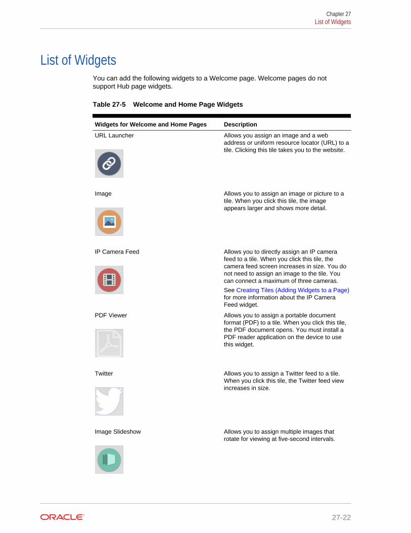
List of WidgetsYou can add the following widgets to a Welcome page. Welcome pages do notsupport Hub page widgets.
Table 27-5 Welcome and Home Page Widgets
Widgets for Welcome and Home Pages Description
URL Launcher
Allows you assign an image and a webaddress or uniform resource locator (URL) to atile. Clicking this tile takes you to the website.
Image
Allows you to assign an image or picture to atile. When you click this tile, the imageappears larger and shows more detail.
IP Camera Feed
Allows you to directly assign an IP camerafeed to a tile. When you click this tile, thecamera feed screen increases in size. You donot need to assign an image to the tile. Youcan connect a maximum of three cameras.
See Creating Tiles (Adding Widgets to a Page)for more information about the IP CameraFeed widget.
PDF Viewer
Allows you to assign a portable documentformat (PDF) to a tile. When you click this tile,the PDF document opens. You must install aPDF reader application on the device to usethis widget.
Allows you to assign a Twitter feed to a tile.When you click this tile, the Twitter feed viewincreases in size.
Image Slideshow
Allows you to assign multiple images thatrotate for viewing at five-second intervals.
Chapter 27List of Widgets
27-22

Table 27-5 (Cont.) Welcome and Home Page Widgets
Widgets for Welcome and Home Pages Description
Today’s Special
Allows you to assign one or more menu items,graphics, descriptions, and prices to a tile.When more than one menu item is configured,the items rotate for viewing at five-secondintervals. You can assign a time range to thiswidget so that different specials cycle basedon the times they are being served.
Command Widget
Allows you to assign procedures, functions,and Ops commands to a tile. The availablecommands are:• Clock In• Clock Out• Update Database• Close Application• Employee Training• Redirect Order Device• Edit Menu Item• Menu Item Availability• Minimize Application• Sign In RVC Prompt
Weather
Allows you to assign a weather forecastprovider and location to a tile. In order to usethis widget, you must purchase an applicationprogram interface (API) key.
Table 27-6 Hub Page Widgets
Widgets for Hub Pages Description
inMotion Charts
Allows you to assign Oracle HospitalityEnterprise Back Office reports to a tile. Whenyou select this tile, the assigned reportgenerates first, but all other reports are alsoaccessible. Select each report to view moreinformation. The available reports are:• Sales• Labor Cost• Discount• Sales Per Labor Hour• Check Count• Guest Count• Average Ticket Time
Chapter 27List of Widgets
27-23

Table 27-6 (Cont.) Hub Page Widgets
Widgets for Hub Pages Description
inMotion Stores
Allows you to view cumulative Sales Reportinformation from all available outlets, or youcan select an individual store from a list thatappears when selecting this tile.
Labor Cost
Allows you to view potential employeeovertime labor costs. When you select this tile,alerts inform the supervisor about employeesapproaching overtime for a particular paycycle.
WCC (Web Configuration Console)
Allows you to assign one of the followingavailable manager procedures to a tile:
• Edit Header/Trailer• Bulk Edit MI Prices• Copy Menu Item
Related Topics
• Understanding Widgets
• The IP Camera Widget
• Adding and Moving Widgets
• Creating Tiles (Adding Widgets to a Page)
• Adding Command Buttons
Viewing the Maximum Data Limit for Hosted EngagementServer
You can view the maximum allowable amount and remaining space for uploadingwidget images to your hosted Engagement server. When adding images for widgets,the data limit (2GB total) appears on the image upload screen, along with theremaining amount of available space for adding more image content.
Related Topics
• Adding and Moving Widgets
Chapter 27Viewing the Maximum Data Limit for Hosted Engagement Server
27-24