Embed Size (px)
Citation preview
Chapter 6 Configuring Radio Settings
6Configuring Radio Settings
This chapter describes how to configure radio settings for the wireless device. This chapter includes these sections:
• Enabling the Radio Interface, page 6-2
• Configuring the Role in Radio Network, page 6-2
• Point-to-point and Multi Point bridging support for 802.11n platforms, page 6-5
• Configuring Radio Data Rates, page 6-8
• Configuring MCS Rates, page 6-11
• Configuring Radio Transmit Power, page 6-12
• Configuring Radio Channel Settings, page 6-16
• Configuring Location-Based Services, page 6-22
• Enabling and Disabling World Mode, page 6-24
• Disabling and Enabling Short Radio Preambles, page 6-25
• Configuring Transmit and Receive Antennas, page 6-26
• Enabling and Disabling Gratuitous Probe Response, page 6-27
• Disabling and Enabling Aironet Extensions, page 6-28
• Configuring the Ethernet Encapsulation Transformation Method, page 6-29
• Enabling and Disabling Reliable Multicast to Workgroup Bridges, page 6-29
• Enabling and Disabling Public Secure Packet Forwarding, page 6-30
• Configuring the Beacon Period and the DTIM, page 6-32
• Configure RTS Threshold and Retries, page 6-32
• Configuring the Maximum Data Retries, page 6-33
• Configuring the Fragmentation Threshold, page 6-34
• Enabling Short Slot Time for 802.11g Radios, page 6-34
• Performing a Carrier Busy Test, page 6-35
• Configuring VoIP Packet Handling, page 6-35
• Viewing VoWLAN Metrics, page 6-36
• Configuring ClientLink, page 6-42
• Debugging Radio Functions, page 6-42
6-1Cisco IOS Software Configuration Guide for Cisco Aironet Access Points
OL-21881-03
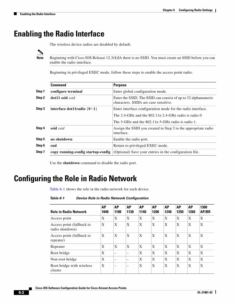
Chapter 6 Configuring Radio SettingsEnabling the Radio Interface
Enabling the Radio InterfaceThe wireless device radios are disabled by default.
Note Beginning with Cisco IOS Release 12.3(8)JA there is no SSID. You must create an SSID before you can enable the radio interface.
Beginning in privileged EXEC mode, follow these steps to enable the access point radio:
Use the shutdown command to disable the radio port.
Configuring the Role in Radio NetworkTable 6-1 shows the role in the radio network for each device.
Command Purpose
Step 1 configure terminal Enter global configuration mode.
Step 2 dot11 ssid ssid Enter the SSID. The SSID can consist of up to 32 alphanumeric characters. SSIDs are case sensitive.
Step 3 interface dot11radio {0 | 1} Enter interface configuration mode for the radio interface.
The 2.4-GHz and the 802.11n 2.4-GHz radio is radio 0
The 5-GHz and the 802.11n 5-GHz radio is radio 1.
Step 4 ssid ssid Assign the SSID you created in Step 2 to the appropriate radio interface.
Step 5 no shutdown Enable the radio port.
Step 6 end Return to privileged EXEC mode.
Step 7 copy running-config startup-config (Optional) Save your entries in the configuration file.
Table 6-1 Device Role in Radio Network Configuration
Role in Radio NetworkAP 1040
AP 1100
AP 1130
AP 1140
AP 1200
AP 1240
AP 1250
AP 1260
1300 AP/BR
Access point X X X X X X X X X
Access point (fallback to radio shutdown)
X X X X X X X X X
Access point (fallback to repeater)
X X X X X X X X X
Repeater X X X X X X X X X
Root bridge X – – X X X X X X
Non-root bridge X – – X X X X X X
Root bridge with wireless clients
X – – X X X X X X
6-2Cisco IOS Software Configuration Guide for Cisco Aironet Access Points
OL-21881-03
Chapter 6 Configuring Radio SettingsConfiguring the Role in Radio Network
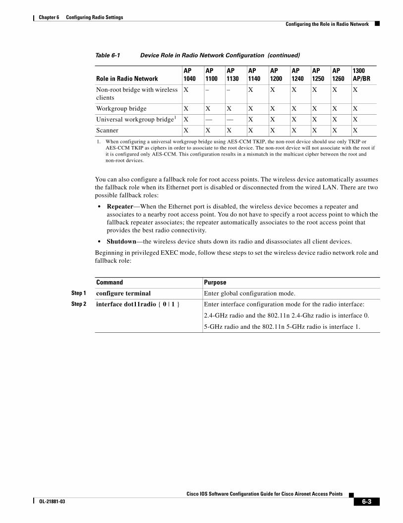
You can also configure a fallback role for root access points. The wireless device automatically assumes the fallback role when its Ethernet port is disabled or disconnected from the wired LAN. There are two possible fallback roles:
• Repeater—When the Ethernet port is disabled, the wireless device becomes a repeater and associates to a nearby root access point. You do not have to specify a root access point to which the fallback repeater associates; the repeater automatically associates to the root access point that provides the best radio connectivity.
• Shutdown—the wireless device shuts down its radio and disassociates all client devices.
Beginning in privileged EXEC mode, follow these steps to set the wireless device radio network role and fallback role:
Non-root bridge with wireless clients
X – – X X X X X X
Workgroup bridge X X X X X X X X X
Universal workgroup bridge1 X — — X X X X X X
Scanner X X X X X X X X X
1. When configuring a universal workgroup bridge using AES-CCM TKIP, the non-root device should use only TKIP or AES-CCM TKIP as ciphers in order to associate to the root device. The non-root device will not associate with the root if it is configured only AES-CCM. This configuration results in a mismatch in the multicast cipher between the root and non-root devices.
Table 6-1 Device Role in Radio Network Configuration (continued)
Role in Radio NetworkAP 1040
AP 1100
AP 1130
AP 1140
AP 1200
AP 1240
AP 1250
AP 1260
1300 AP/BR
Command Purpose
Step 1 configure terminal Enter global configuration mode.
Step 2 interface dot11radio { 0 | 1 } Enter interface configuration mode for the radio interface:
2.4-GHz radio and the 802.11n 2.4-Ghz radio is interface 0.
5-GHz radio and the 802.11n 5-GHz radio is interface 1.
6-3Cisco IOS Software Configuration Guide for Cisco Aironet Access Points
OL-21881-03
Chapter 6 Configuring Radio SettingsConfiguring the Role in Radio Network
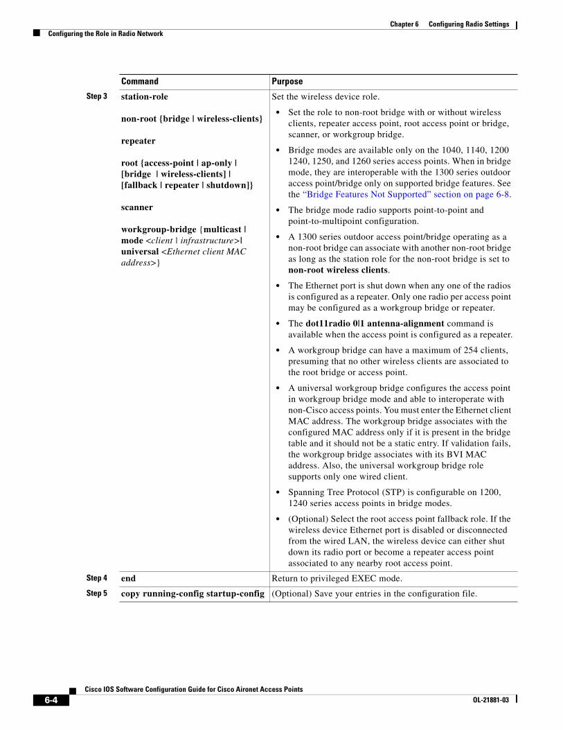
Step 3 station-role
non-root {bridge | wireless-clients}
repeater
root {access-point | ap-only | [bridge | wireless-clients] | [fallback | repeater | shutdown]}
scanner
workgroup-bridge {multicast | mode <client | infrastructure>| universal <Ethernet client MAC address>}
Set the wireless device role.
• Set the role to non-root bridge with or without wireless clients, repeater access point, root access point or bridge, scanner, or workgroup bridge.
• Bridge modes are available only on the 1040, 1140, 1200 1240, 1250, and 1260 series access points. When in bridge mode, they are interoperable with the 1300 series outdoor access point/bridge only on supported bridge features. See the “Bridge Features Not Supported” section on page 6-8.
• The bridge mode radio supports point-to-point and point-to-multipoint configuration.
• A 1300 series outdoor access point/bridge operating as a non-root bridge can associate with another non-root bridge as long as the station role for the non-root bridge is set to non-root wireless clients.
• The Ethernet port is shut down when any one of the radios is configured as a repeater. Only one radio per access point may be configured as a workgroup bridge or repeater.
• The dot11radio 0|1 antenna-alignment command is available when the access point is configured as a repeater.
• A workgroup bridge can have a maximum of 254 clients, presuming that no other wireless clients are associated to the root bridge or access point.
• A universal workgroup bridge configures the access point in workgroup bridge mode and able to interoperate with non-Cisco access points. You must enter the Ethernet client MAC address. The workgroup bridge associates with the configured MAC address only if it is present in the bridge table and it should not be a static entry. If validation fails, the workgroup bridge associates with its BVI MAC address. Also, the universal workgroup bridge role supports only one wired client.
• Spanning Tree Protocol (STP) is configurable on 1200, 1240 series access points in bridge modes.
• (Optional) Select the root access point fallback role. If the wireless device Ethernet port is disabled or disconnected from the wired LAN, the wireless device can either shut down its radio port or become a repeater access point associated to any nearby root access point.
Step 4 end Return to privileged EXEC mode.
Step 5 copy running-config startup-config (Optional) Save your entries in the configuration file.
Command Purpose
6-4Cisco IOS Software Configuration Guide for Cisco Aironet Access Points
OL-21881-03
Chapter 6 Configuring Radio SettingsConfiguring the Role in Radio Network
Note When you enable the role in the radio network as a Bridge/workgroup bridge and enable the interface using the no shut command, the physical status and the software status of the interface will be up only if the the device on the other end access point or bridge is up. Otherwise, only the physical status of the device will be up. The software status of the device comes up only when the device on the other end is configured and up.
Universal Workgroup Bridge ModeWhen configuring the universal workgroup bridge roll, you must include the client MAC address. The workgroup bridge will associate with this MAC address only if it is present in the bridge table and is not a static entry. If validation fails, the workgroup bridge associates with its BVI MAC address. In universal workgroup bridge mode, the workgroup bridge uses the Ethernet client MAC address to associate with Cisco or non-Cisco root devices. The universal workgroup bridge is transparent and is not managed.
Note The universal workgroup bridge role supports only one wired client.
You can enable a recovery mechanism and make the workgroup bridge manageable again by disabling the Ethernet client, causing the universal workgroup bridge to associate with an access point using its own BVI address.
A roaming keyword has been added to the world-mode command to support an “airline flying between different countries” scenario. The keyword causes the workgroup bridge to do passive scanning once it is deathenticated from a root access point. See the “Enabling and Disabling World Mode” section on page 6-24 for more information on this command.
Point-to-point and Multi Point bridging support for 802.11n platformsThe point-to-point and point-to-multipoint bridging is supported on the Cisco Aironet 1040, 1140, 1250 Series Access Points (802.11n platforms). The 5 GHz bands support 20- and 40-MHz and the 2.4-GHz bands support 20 MHz.
The following items are supported for AP1040, AP1140, AP1250, and AP1260 bridging:
• MIMO, short-range bridging (on campus or inter-building bridge deployments), with dipole and MIMO antennas (line of sight and short range) under 1 Km.
• 20-MHz and 40-MHz 802.11n support.
• Workgroup bridge (WGB) short-range support.
• SISO (single-in, single-out), MCS 0-7 and legacy bridge rates (802.11 a/b/g and 802.11n) using one outdoor antenna.
Note This is only supported using short range links and is not a replacement for the AP-1240/1300/1400 or other Bridge products.
The following items are not supported for AP1040, AP1140, AP1250, and AP1260 bridging:
• The distance CLI command; long-range links over 1 Km currently are not supported, so the distance command is not supported.
6-5Cisco IOS Software Configuration Guide for Cisco Aironet Access Points
OL-21881-03
Chapter 6 Configuring Radio SettingsConfiguring the Role in Radio Network
• Outdoor MIMO bridging using external antennas has not been fully tested and is not fully supported with this release.
Note In point-to-multipoint bridging, WGB is not recommended with the root bridge. WGB should be associated to the root AP in point-to-multipoint bridging setup.
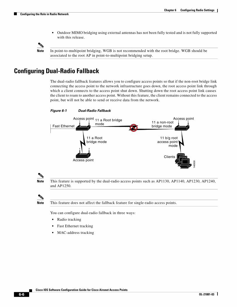
Configuring Dual-Radio FallbackThe dual-radio fallback features allows you to configure access points so that if the non-root bridge link connecting the access point to the network infrastructure goes down, the root access point link through which a client connects to the access point shut down. Shutting down the root access point link causes the client to roam to another access point. Without this feature, the client remains connected to the access point, but will not be able to send or receive data from the network.
Figure 6-1 Dual-Radio Fallback
Note This feature is supported by the dual-radio access points such as AP1130, AP1140, AP1230, AP1240, and AP1250.
Note This feature does not affect the fallback feature for single-radio access points.
You can configure dual-radio fallback in three ways:
• Radio tracking
• Fast Ethernet tracking
• MAC-address tracking
Access point
Fast Ethernet
11 a Rootbridge mode
11 b/g rootaccess point
mode
11 a Root bridgemode 11 a non-root
bridge mode
1469
30
Access pointClients
Access point
6-6Cisco IOS Software Configuration Guide for Cisco Aironet Access Points
OL-21881-03
Chapter 6 Configuring Radio SettingsConfiguring the Role in Radio Network
Radio TrackingYou can configure the access point to track or monitor the status of one of its radios. It the tracked radio goes down or is disabled, the access point shuts down the other radio. If the tracked radio comes up, the access point enables the other radio.
• To track radio 0, enter the following command:
# station-role root access-point fallback track d0 shutdown
• To track radio 1, enter the following command:
# station-role root access-point fallback track d1 shutdown
Note This command is not supported by 802.11n series access points (such as AP1260), you must use the following command in the radio interface configuration mode:
# station-role root access-point fallback shutdown
Fast Ethernet TrackingYou can configure the access point for fallback when its Ethernet port is disabled or disconnected from the wired LAN. You configure the access point for fast Ethernet tracking as described in the “Configuring the Role in Radio Network” section on page 6-2.
Note Fast Ethernet tracking does not support the Repeater mode.
• To configure non-802.11n access points for Fast Ethernet tracking, in the radio interfaces configuration mode enter the following command:
# station-role root access-point fallback track fa 0
• To configure 802.11n access points (such as AP1040, AP1140, AP1250, and AP1260) for Gigabit Ethernet tracking, in the radio interfaces configuration mode enter the following command:
# station-role root fallback shutdown
MAC-Address TrackingYou can configure the radio whose role is root access point to go up or down by tracking a client access point, using its MAC address, on another radio. If the client disassociates from the access point, the root access point radio goes down. If the client reassociates to the access point, the root access point radio comes back up.
MAC-address tracking is most useful when the client is a non-root bridge access point connected to an upstream wired network.
For example, to track a client whose MAC address is 12:12:12:12:12:12, enter the following command:
# station-role root access-point fallback track mac-address 12:12:12:12:12:12 shutdown
6-7Cisco IOS Software Configuration Guide for Cisco Aironet Access Points
OL-21881-03
Chapter 6 Configuring Radio SettingsConfiguring Radio Data Rates
Bridge Features Not SupportedThe following features are not supported when a 1200 or 1240 series access point is configured as a bridge:
• Clear Channel Assessment (CCA)
• Interoperability with 1400 series bridge
• Concatenation
• Install mode
• EtherChannel and PageP configuration on switch
Configuring Radio Data RatesYou use the data rate settings to choose the data rates the wireless device uses for data transmission. The rates are expressed in megabits per second. The wireless device always attempts to transmit at the highest data rate set to Basic, also called Require on the browser-based interface. If there are obstacles or interference, the wireless device steps down to the highest rate that allows data transmission. You can set each data rate to one of three states:
• Basic (the GUI labels Basic rates as Required)—Allows transmission at this rate for all packets, both unicast and multicast. At least one of the wireless device's data rates must be set to Basic.
• Enabled—The wireless device transmits only unicast packets at this rate; multicast packets are sent at one of the data rates set to Basic.
• Disabled—The wireless device does not transmit data at this rate.
Note At least one data rate must be set to basic.
You can use the Data Rate settings to set an access point to serve client devices operating at specific data rates. For example, to set the 2.4-GHz radio for 11 megabits per second (Mbps) service only, set the 11-Mbps rate to Basic and set the other data rates to Disabled. To set the wireless device to serve only client devices operating at 1 and 2 Mbps, set 1 and 2 to Basic and set the rest of the data rates to Disabled. To set the 2.4-GHz, 802.11g radio to serve only 802.11g client devices, set any Orthogonal Frequency Division Multiplexing (OFDM) data rate (6, 9, 12, 18, 24, 36, 48, 54) to Basic. To set the 5-GHz radio for 54 Mbps service only, set the 54-Mbps rate to Basic and set the other data rates to Disabled.
You can configure the wireless device to set the data rates automatically to optimize either the range or the throughput. When you enter range for the data rate setting, the wireless device sets the 1 Mbps rate to basic and the other rates to enabled. The range setting allows the access point to extend the coverage area by compromising on the data rate. Therefore, if you have a client that is not able to connect to the access point while other clients can, one reason may be because the client is not within the coverage area of the access point. In such a case using the range option will help in extending the coverage area and the client may be able to connect to the access point. Typically the trade-off is between throughput and range. When the signal degrades (possibly due to distance from the access point,) the rates will renegotiate down in order to maintain the link (but at a lower data rate). Contrast that against a link configured for a higher throughput that will simply drop when the signal degrades enough to no longer sustain a configured high data rate, or roam to another access point with sufficient coverage, if one is available. The balance between the two (throughput vs. range) is one of those design decisions that has
6-8Cisco IOS Software Configuration Guide for Cisco Aironet Access Points
OL-21881-03
Chapter 6 Configuring Radio SettingsConfiguring Radio Data Rates
to be made based on resources available to the wireless project, type of traffic the users will be passing, service level desired, and as always, the quality of the RF environment.When you enter throughput for the data rate setting, the wireless device sets all four data rates to basic.
Note When a wireless network has a mixed environment of 802.11b clients and 802.11g clients, make sure that data rates 1, 2, 5.5, and 11 Mbps are set to required (basic) and that all other data rates are set to enable. The 802.11b adapters do not recognize the 54 Mbps data rate and do not operate if data rates higher than 11Mbps are set to require on the connecting access point.
Access Points Send Multicast and Management Frames at Highest Basic RateAccess points running recent Cisco IOS versions are transmitting multicast and management frames at the highest configured basic rate, and is a situation that could causes reliability problems.
Access points running LWAPP or autonomous IOS should transmit multicast and management frames at the lowest configured basic rate. This is necessary in order to provide for good coverage at the cell's edge, especially for unacknowledged multicast transmissions where multicast wireless transmissions may fail to be received.
Since multicast frames are not retransmitted at the MAC layer, stations at the edge of the cell may fail to receive them successfully. If reliable reception is a goal, then multicasts should be transmitted at a low data rate. If support for high data rate multicasts is required, then it may be useful to shrink the cell size and to disable all lower data rates.
Depending on your specific requirements, you can take the following action:
• If you need to transmit the multicast data with the greatest reliability and if there is no need for great multicast bandwidth, then configure a single basic rate, one that is low enough to reach the edges of the wireless cells.
• If you need to transmit the multicast data at a certain data rate in order to achieve a certain throughput, then configure that rate as the highest basic rate. You can also set a lower basic rate for coverage of non-multicast clients.
Beginning in privileged EXEC mode, follow these steps to configure the radio data rates:
Command Purpose
Step 1 configure terminal Enter global configuration mode.
Step 2 interface dot11radio {0 | 1} Enter interface configuration mode for the radio interface. The 2.4-GHz radio and 2.4-GHz N radio is radio 0, and the 5-GHz radio and 5-GHz N radios radio 1.
6-9Cisco IOS Software Configuration Guide for Cisco Aironet Access Points
OL-21881-03
Chapter 6 Configuring Radio SettingsConfiguring Radio Data Rates
Step 3 speed
802.11b, 2.4-GHz radio:
{[1.0] [11.0] [2.0] [5.5] [basic-1.0] [basic-11.0] [basic-2.0] [basic-5.5] | range | throughput}
802.11g, 2.4-GHz radio:
{[1.0] [2.0] [5.5] [6.0] [9.0] [11.0] [12.0] [18.0] [24.0] [36.0] [48.0] [54.0] [basic-1.0] [basic-2.0] [basic-5.5] [basic-6.0] [basic-9.0] [basic-11.0] [basic-12.0] [basic-18.0] [basic-24.0] [basic-36.0] [basic-48.0] [basic-54.0] | range | throughput [ofdm] | default }
802.11a 5-GHz radio:
{[6.0] [9.0] [12.0] [18.0] [24.0] [36.0] [48.0] [54.0] [basic-6.0] [basic-9.0] [basic-12.0] [basic-18.0] [basic-24.0] [basic-36.0] [basic-48.0] [basic-54.0] |range | throughput | default}
802.11n 2.4-GHz radio:
{[1.0] [11.0] [12.0] [18.0] [2.0] [24.0] [36.0] [48.0] [5.5] [54.0] [6.0] [9.0] [basic-1.0] [basic-11.0] [basic-12.0] [basic-18.0] [basic-24.0] [basic-36.0] [basic-48.0] [basic-5.5] [basic-54.0] [basic-6.0] [basic-9.0] [default] [m0-7] [m0.] [m1.] [m10.] [m11.] [m12.] [m13.] [m14.] [m15.] [m2.] [m3.] [m4.] [m5.] [m6.] [m7.] [m8-15] [m8.] [m9.] [ofdm] [only-ofdm] | range | throughput}
802.11n 5-GHz radio:
{[12.0] [18.0] [24.0] [36.0] [48.0] [54.0] [6.0] [9.0] [basic-12.0] [basic-18.0] [basic-24.0] [basic-36.0] [basic-48.0] [basic-54.0] [basic-6.0] [basic-9.0] [default] [m0-7] [m0.] [m1.] [m10.] [m11.] [m12.] [m13.] [m14.] [m15.] [m2.] [m3.] [m4.] [m5.] [m6.] [m7.] [m8-15] [m8.] [m9.] | range | throughput}
Set each data rate to basic or enabled, or enter range to optimize range or throughput to optimize throughput.
• (Optional) Enter 1.0, 2.0, 5.5, and 11.0 to set these data rates to enabled on the 802.11b, 2.4-GHz radio.
Enter 1.0, 2.0, 5.5, 6.0, 9.0, 11.0, 12.0, 18.0, 24.0, 36.0, 48.0, and 54.0 to set these data rates to enabled on the 802.11g, 2.4-GHz radio.
Enter 6.0, 9.0, 12.0, 18.0, 24.0, 36.0, 48.0, and 54.0 to set these data rates to enabled on the 5-GHz radio.
• (Optional) Enter basic-1.0, basic-2.0, basic-5.5, and basic-11.0 to set these data rates to basic on the 802.11b, 2.4-GHz radio.
Enter basic-1.0, basic-2.0, basic-5.5, basic-6.0, basic-9.0, basic-11.0, basic-12.0, basic-18.0, basic-24.0, basic-36.0, basic-48.0, and basic-54.0 to set these data rates to basic on the 802.11g, 2.4-GHz radio.
Note The client must support the basic rate that you select or it cannot associate to the wireless device. If you select 12 Mbps or higher for the basic data rate on the 802.11g radio, 802.11b client devices cannot associate to the wireless device 802.11g radio.
Enter basic-6.0, basic-9.0, basic-12.0, basic-18.0, basic-24.0, basic-36.0, basic-48.0, and basic-54.0 to set these data rates to basic on the 5-GHz radio.
• (Optional) Enter range or throughput to automatically optimize radio range or throughput. When you enter range, the wireless device sets the lowest data rate to basic and the other rates to enabled. When you enter throughput, the wireless device sets all data rates to basic.
(Optional) On the 802.11g radio, enter speed throughput ofdm to set all OFDM rates (6, 9, 12, 18, 24, 36, and 48) to basic (required) and set all the CCK rates (1, 2, 5.5, and 11) to disabled. This setting disables 802.11b protection mechanisms and provides maximum throughput for 802.11g clients. However, it prevents 802.11b clients from associating to the access point.
• (Optional) Enter default to set the data rates to factory default settings (not supported on 802.11b radios).
On the 802.11g radio, the default option sets rates 1, 2, 5.5, and 11 to basic, and rates 6, 9, 12, 18, 24, 36, 48, and 54 to enabled. These rate settings allow both 802.11b and 802.11g client devices to associate to the wireless device 802.11g radio.
On the 5-GHz radio, the default option sets rates 6.0, 12.0, and 24.0 to basic, and rates 9.0, 18.0, 36.0, 48.0, and 54.0 to enabled.
Command Purpose
6-10Cisco IOS Software Configuration Guide for Cisco Aironet Access Points
OL-21881-03
Chapter 6 Configuring Radio SettingsConfiguring MCS Rates
Use the no form of the speed command to remove one or more data rates from the configuration. This example shows how to remove data rates basic-2.0 and basic-5.5 from the configuration:
ap1200# configure terminalap1200(config)# interface dot11radio 0ap1200(config-if)# no speed basic-2.0 basic-5.5ap1200(config-if)# end
Configuring MCS RatesModulation Coding Scheme (MCS) is a specification of PHY parameters consisting of modulation order (BPSK, QPSK, 16-QAM, 64-QAM) and FEC code rate (1/2, 2/3, 3/4, 5/6). MCS is used in 1140 and 1250 series 802.11n radios, which define 32 symmetrical settings (8 per spatial stream):
• MCS 0–7
• MCS 8–15
• MCS 16–23
• MCS 24–31
The 1140 and 1250 series access point supports MCS 0–15. High throughput clients support at least MCS 0–7.
MCS is an important setting because it provides for potentially greater throughput. High throughput data rates are a function of MCS, bandwidth, and guard interval. 802.11 a, b, and g radios use 20-MHz channel widths. Table 6-2 shows potential data rates based on MCS, guard interval, and channel width.
Note The 2.5 GHz radios do not support 40 MHz channel width.
speed (continued) On the 802.11n 2.4-GHz radio, the default option sets rates 1.0, 2.0, 5.5, and 11.0 to enabled.
On the 802.11n 5-GHz radio, the default option sets rates to 6.0, 12.0, and 24.0 to enabled.
The default MCS rate setting for both 802.11n radios is 0–15.
Step 4 end Return to privileged EXEC mode.
Step 5 copy running-config startup-config (Optional) Save your entries in the configuration file.
Command Purpose
Table 6-2 Data Rates Based on MCS Settings, Guard Interval, and Channel Width
MCS Index Guard Interval = 800ns Guard Interval = 400ns
20-MHz Channel Width Data Rate (Mbps)
40-MHz Channel Width Data Rate (Mbps)
20-MHz Channel Width Data Rate (Mbps)
40-MHz Channel Width Data Rate (Mbps)
0 6.5 13.5 7 2/9 15
1 13 27 14 4/9 30
6-11Cisco IOS Software Configuration Guide for Cisco Aironet Access Points
OL-21881-03
Chapter 6 Configuring Radio SettingsConfiguring Radio Transmit Power
MCS rates are configured using the speed command. The following example shows a speed setting for an 802.11n 5-GHz radio:
interface Dot11Radio0no ip addressno ip route-cache!ssid 1250test!speed basic-1.0 2.0 5.5 11.0 6.0 9.0 12.0 18.0 24.0 36.0 48.0 54.0 m0. m1. m2. m3. m4. m8. m9. m10. m11. m12. m13. m14. m15.
Configuring Radio Transmit PowerRadio transmit power is based on the type of radio or radios installed in your access point and the regulatory domain in which it operates. To determine what transmit power is available for your access point and which regulatory domain it operates in, refer to the hardware installation guide for that device. hardware installation guides are available at cisco.com. Follow these steps to view and download them:
Step 1 Browse to http://www.cisco.com.
20-MHz Channel Width Data Rate (Mbps)
40-MHz Channel Width Data Rate (Mbps)
20-MHz Channel Width Data Rate (Mbps)
40-MHz Channel Width Data Rate (Mbps)
2 19.5 40.5 21 2/3 45
3 26 54 28 8/9 60
4 39 81 43 1/3 90
5 52 109 57 5/9 120
6 58.5 121.5 65 135
7 65 135 72 2/9 152.5
8 13 27 14 4/9 30
9 26 54 28 8/9 60
10 39 81 43 1/3 90
11 52 108 57 7/9 120
12 78 162 86 2/3 180
13 104 216 115 5/9 240
14 117 243 130 270
15 130 270 144 4/9 300
The legacy rates are:
5-GHz: 6, 9, 12, 18, 24, 36, 48, and 54 Mbps
2.4-GHz: 1, 2, 5.5, 6, 9, 11, 12, 18, 24, 36, 48, and 54 Mbps
Table 6-2 Data Rates Based on MCS Settings, Guard Interval, and Channel Width (continued)
MCS Index Guard Interval = 800ns Guard Interval = 400ns
6-12Cisco IOS Software Configuration Guide for Cisco Aironet Access Points
OL-21881-03
Chapter 6 Configuring Radio SettingsConfiguring Radio Transmit Power
Step 2 Click Technical Support & Documentation. A small window appears containing a list of technical support links.
Step 3 Click Technical Support & Documentation. The Technical Support and Documentation page appears.
Step 4 In the Documentation & Tools section, choose Wireless. The Wireless Support Resources page appears.
Step 5 In the Wireless LAN Access section, choose the device you are working with. An introduction page for the device appears.
Step 6 In the Install and Upgrade section, choose Install and Upgrade Guides. The Install and Upgrade Guides page for the device appears.
Step 7 Choose the hardware installation guide for the device. The home page for the guide appears.
Step 8 In the left frame, click Channels and Antenna Settings.
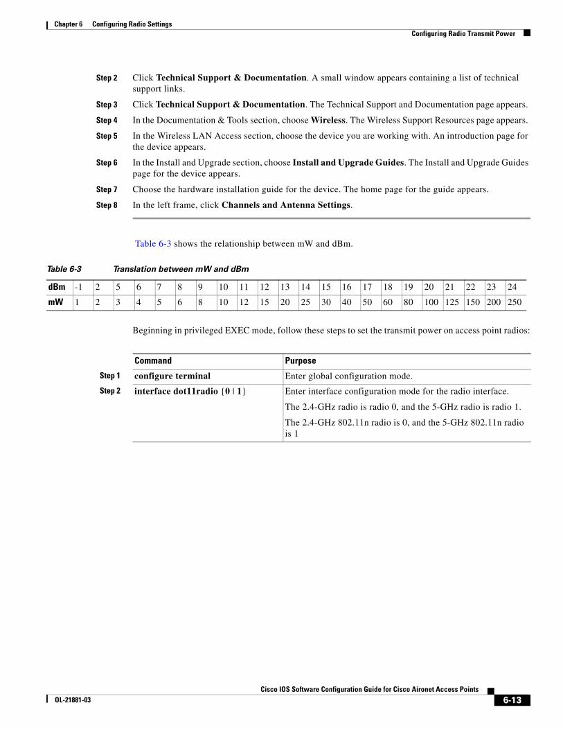
Table 6-3 shows the relationship between mW and dBm.
Table 6-3 Translation between mW and dBm
Beginning in privileged EXEC mode, follow these steps to set the transmit power on access point radios:
dBm -1 2 5 6 7 8 9 10 11 12 13 14 15 16 17 18 19 20 21 22 23 24
mW 1 2 3 4 5 6 8 10 12 15 20 25 30 40 50 60 80 100 125 150 200 250
Command Purpose
Step 1 configure terminal Enter global configuration mode.
Step 2 interface dot11radio {0 | 1} Enter interface configuration mode for the radio interface.
The 2.4-GHz radio is radio 0, and the 5-GHz radio is radio 1.
The 2.4-GHz 802.11n radio is 0, and the 5-GHz 802.11n radio is 1
6-13Cisco IOS Software Configuration Guide for Cisco Aironet Access Points
OL-21881-03
Chapter 6 Configuring Radio SettingsConfiguring Radio Transmit Power
Use the no form of the power command to return the power setting to maximum, the default setting.
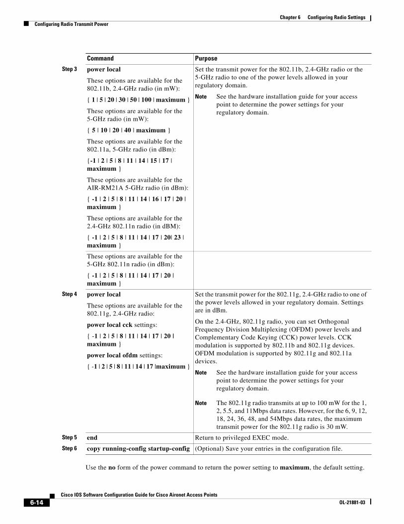
Step 3 power local
These options are available for the 802.11b, 2.4-GHz radio (in mW):
{ 1 | 5 | 20 | 30 | 50 | 100 | maximum }
These options are available for the 5-GHz radio (in mW):
{ 5 | 10 | 20 | 40 | maximum }
These options are available for the 802.11a, 5-GHz radio (in dBm):
{-1 | 2 | 5 | 8 | 11 | 14 | 15 | 17 | maximum }
These options are available for the AIR-RM21A 5-GHz radio (in dBm):
{ -1 | 2 | 5 | 8 | 11 | 14 | 16 | 17 | 20 | maximum }
These options are available for the 2.4-GHz 802.11n radio (in dBM):
{ -1 | 2 | 5 | 8 | 11 | 14 | 17 | 20| 23 | maximum }
Set the transmit power for the 802.11b, 2.4-GHz radio or the 5-GHz radio to one of the power levels allowed in your regulatory domain.
Note See the hardware installation guide for your access point to determine the power settings for your regulatory domain.
These options are available for the 5-GHz 802.11n radio (in dBm):
{ -1 | 2 | 5 | 8 | 11 | 14 | 17 | 20 | maximum }
Step 4 power local
These options are available for the 802.11g, 2.4-GHz radio:
power local cck settings:
{ -1 | 2 | 5 | 8 | 11 | 14 | 17 | 20 | maximum }
power local ofdm settings:
{ -1 | 2 | 5 | 8 | 11 | 14 | 17 |maximum }
Set the transmit power for the 802.11g, 2.4-GHz radio to one of the power levels allowed in your regulatory domain. Settings are in dBm.
On the 2.4-GHz, 802.11g radio, you can set Orthogonal Frequency Division Multiplexing (OFDM) power levels and Complementary Code Keying (CCK) power levels. CCK modulation is supported by 802.11b and 802.11g devices. OFDM modulation is supported by 802.11g and 802.11a devices.
Note See the hardware installation guide for your access point to determine the power settings for your regulatory domain.
Note The 802.11g radio transmits at up to 100 mW for the 1, 2, 5.5, and 11Mbps data rates. However, for the 6, 9, 12, 18, 24, 36, 48, and 54Mbps data rates, the maximum transmit power for the 802.11g radio is 30 mW.
Step 5 end Return to privileged EXEC mode.
Step 6 copy running-config startup-config (Optional) Save your entries in the configuration file.
Command Purpose
6-14Cisco IOS Software Configuration Guide for Cisco Aironet Access Points
OL-21881-03
Chapter 6 Configuring Radio SettingsConfiguring Radio Transmit Power
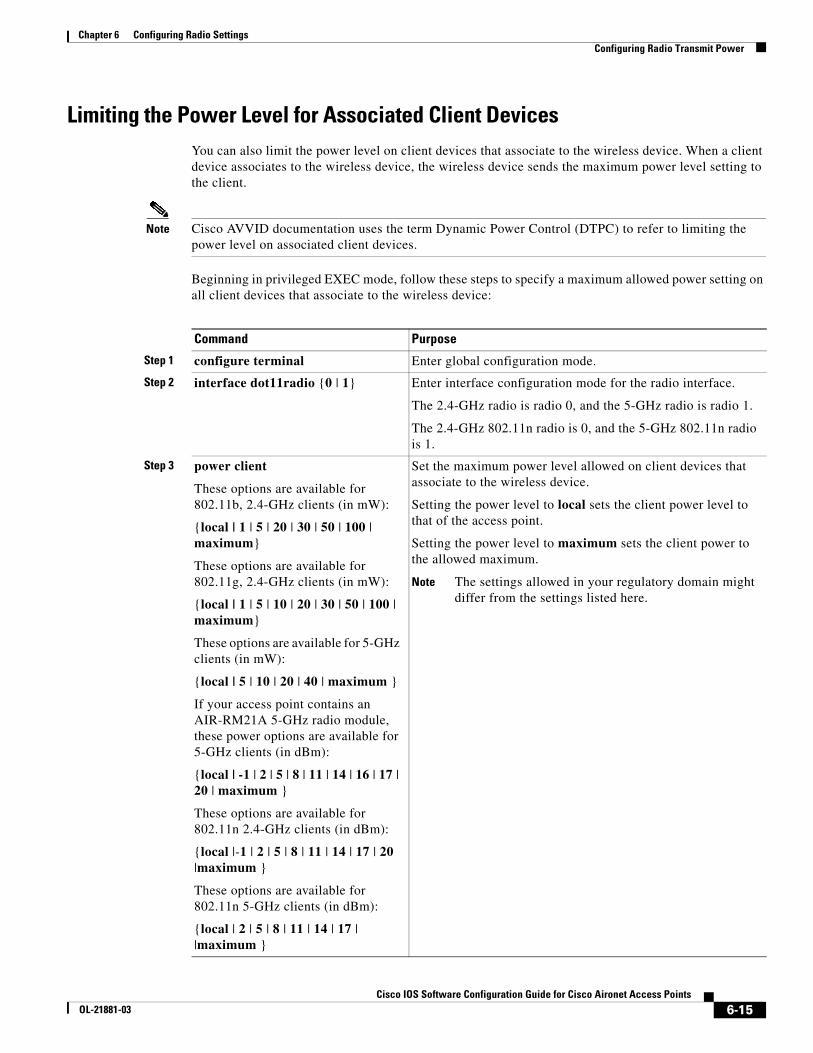
Limiting the Power Level for Associated Client DevicesYou can also limit the power level on client devices that associate to the wireless device. When a client device associates to the wireless device, the wireless device sends the maximum power level setting to the client.
Note Cisco AVVID documentation uses the term Dynamic Power Control (DTPC) to refer to limiting the power level on associated client devices.
Beginning in privileged EXEC mode, follow these steps to specify a maximum allowed power setting on all client devices that associate to the wireless device:
Command Purpose
Step 1 configure terminal Enter global configuration mode.
Step 2 interface dot11radio {0 | 1} Enter interface configuration mode for the radio interface.
The 2.4-GHz radio is radio 0, and the 5-GHz radio is radio 1.
The 2.4-GHz 802.11n radio is 0, and the 5-GHz 802.11n radio is 1.
Step 3 power client
These options are available for 802.11b, 2.4-GHz clients (in mW):
{local | 1 | 5 | 20 | 30 | 50 | 100 | maximum}
These options are available for 802.11g, 2.4-GHz clients (in mW):
{local | 1 | 5 | 10 | 20 | 30 | 50 | 100 | maximum}
These options are available for 5-GHz clients (in mW):
{local | 5 | 10 | 20 | 40 | maximum }
If your access point contains an AIR-RM21A 5-GHz radio module, these power options are available for 5-GHz clients (in dBm):
{local | -1 | 2 | 5 | 8 | 11 | 14 | 16 | 17 | 20 | maximum }
These options are available for 802.11n 2.4-GHz clients (in dBm):
{local |-1 | 2 | 5 | 8 | 11 | 14 | 17 | 20 |maximum }
These options are available for 802.11n 5-GHz clients (in dBm):
{local | 2 | 5 | 8 | 11 | 14 | 17 | |maximum }
Set the maximum power level allowed on client devices that associate to the wireless device.
Setting the power level to local sets the client power level to that of the access point.
Setting the power level to maximum sets the client power to the allowed maximum.
Note The settings allowed in your regulatory domain might differ from the settings listed here.
6-15Cisco IOS Software Configuration Guide for Cisco Aironet Access Points
OL-21881-03
Chapter 6 Configuring Radio SettingsConfiguring Radio Channel Settings
Use the no form of the client power command to disable the maximum power level for associated clients.
Note Aironet extensions must be enabled to limit the power level on associated client devices. Aironet extensions are enabled by default.
Configuring Radio Channel SettingsThe default channel setting for the wireless device radios is least congested; at startup, the wireless device scans for and selects the least-congested channel. For the most consistent performance after a site survey, however, we recommend that you assign a static channel setting for each access point. The channel settings on the wireless device correspond to the frequencies available in your regulatory domain. See the access point hardware installation guide for the frequencies allowed in your domain.
Note In places where RF interference might be causing clients to occasionally get disconnected from the wireless network, setting the wireless interface to run on a different channel, such as channel 1 (2412), might avoid the interference.
Note Cisco Aironet CB20A client radios sometimes fail to associate to the AIR-RM21A radio module because the CB20A client does not support all the channels supported by the AIR-RM21A radio module. The default channel setting for the AIR-RM21A radio module, least congested, often results in the access point settling on one of these frequencies that the CB20A client radio does not support: channel 149 (5745 GHz), channel 153 (5765 GHz), channel 157 (5785 GHz), and channel 161 (5805 GHz). To avoid this problem, set the channel on the AIR-RM21A radio module to one of the channels supported by the CB20A client.
Each 2.4-GHz channel covers 22 MHz. The bandwidth for channels 1, 6, and 11 does not overlap, so you can set up multiple access points in the same vicinity without causing interference. Both 802.11b and 802.11g 2.4-GHz radios use the same channels and frequencies.
The 5-GHz radio operates on eight channels from 5180 to 5320 MHz. Each channel covers 20 MHz, and the bandwidth for the channels overlaps slightly. For best performance, use channels that are not adjacent (44 and 46, for example) for radios that are close to each other.
Note Too many access points in the same vicinity creates radio congestion that can reduce throughput. A careful site survey can determine the best placement of access points for maximum radio coverage and throughput.
Step 4 end Return to privileged EXEC mode.
Step 5 copy running-config startup-config (Optional) Save your entries in the configuration file.
Command Purpose
6-16Cisco IOS Software Configuration Guide for Cisco Aironet Access Points
OL-21881-03
Chapter 6 Configuring Radio SettingsConfiguring Radio Channel Settings
Because they change frequently, channel settings are not included in this document. For up-to-date information on channel settings for your access point or bridge, see the Channels and Maximum Power Settings for Cisco Aironet Autonomous Access Points and Bridges. This document is available on cisco.com at the following URL:
http://cisco.com/en/US/products/ps6521/tsd_products_support_install_and_upgrade.html
802.11n Channel Widths802.11n allows both 20-MHz and 40-Mhz channel widths consisting of 2 contiguous non-overlapping channels (for example, 2.4-GHz channels 1 and 6)
One of the 20-MHz channels is called the control channel. Legacy clients and 20-MHz high throughput clients use the control channel. Beacons can only be sent on this channel. The second 20-MHz channel is called the extension channel. 40-MHz stations may use this channel and the control channel simultaneously.
A 40-MHz channel is specified as a channel and extension, such as 1,1. In this example, the control channel is channel 1 and the extension channel is above it.
Beginning in privileged EXEC mode, follow these steps to set the wireless device channel width:
Command Purpose
Step 1 configure terminal Enter global configuration mode.
Step 2 interface dot11radio {0 | 1} Enter interface configuration mode for the radio interface.
The 2.4-GHz radio and the 802.11n 2.4-GHz is radio 0.
The 5-GHz radio and the 802.11n 5-GHz is radio 1.
Step 3 channel{frequency | least-congested | width [20 | 40-above | 40-below] | dfs}
Set the default channel for the wireless device radio. To search for the least-congested channel on startup, enter least-congested.
Use the width option to specify a bandwidth to use. This option is available for 1140 and 1250 series access point and consists of three available settings: 20, 40-above, and 40-below. choosing 20 sets the channel width to 20 MHz. Choosing 40-above sets the channel width to 40 Mhz with the extension channel above the control channel. Choosing 40-below sets the channel width to 40 MHz with the extension channel below the control channel.
Note The channel command is disabled for 5-GHz radios that comply with European Union regulations on dynamic frequency selection (DFS). See the “Setting the 802.11n Guard Interval” section on page 6-22 for more information.
Step 4 end Return to privileged EXEC mode.
Step 5 copy running-config startup-config
(Optional) Save your entries in the configuration file.
6-17Cisco IOS Software Configuration Guide for Cisco Aironet Access Points
OL-21881-03
Chapter 6 Configuring Radio SettingsConfiguring Radio Channel Settings
Dynamic Frequency SelectionAccess points with 5-GHz radios configured at the factory for use in the United States, Europe, Singapore, Korea, Japan, Israel, and Taiwan now comply with regulations that require radio devices to use Dynamic Frequency Selection (DFS) to detect radar signals and avoid interfering with them. When an access points detects a radar on a certain channel, it avoids using that channel for 30 minutes. Radios configured for use in other regulatory domains do not use DFS.
When a DFS-enabled 5-GHz radio operates on one of the 15 channels listed in Table 6-4, the access point automatically uses DFS to set the operating frequency. When DFS is enabled, the access point monitors its operating frequency for radar signals. If it detects radar signals on the channel, the access point takes these steps:
• Blocks new transmissions on the channel.
• Flushes the power-save client queues.
• Broadcasts an 802.11h channel-switch announcement.
• Disassociates remaining client devices.
• If participating in WDS, sends a DFS notification to the active WDS device that it is leaving the frequency.
• Randomly selects a different 5-GHz channel.
• If the channel selected is one of the channels in Table 6-4, scans the new channel for radar signals for 60 seconds.
• If there are no radar signals on the new channel, enables beacons and accepts client associations.
• If participating in WDS, sends a DFS notification of its new operating frequency to the active WDS device.
Note You cannot manually select a channel for DFS-enabled 5-GHz radios in some regions, depending on the regulatory requirements. The access points randomly selects a channel in that case.
The full list of channels that require DFS is shown in Table 6-4.
For autonomous operation, DFS requires random channel selection among the channels listed in Table 6-4. The channels not listed in Table 6-4 do not require random selection and may be manually configured.
Channels requiring Dynamic Frequency Selection (DFS) may be manually selected for the 1040, 1130, 1140, 1230, 1240, 1250, 1260 and 1520 using the the -E or -M regulatory domains, or 1430 using -A, -E, or -M domains. The same GUI/CLI used to manually configure non-DFS channels can be used to select DFS channels as well. The default channel selection is "DFS", which randomly selects a channel.
Table 6-4 DFS Channel List
Channel Frequency Channel Frequency Channel Frequency
52 5260 MHz 104 5500 MHz 124 5620 MHz
56 5280 MHz 108 5520 MHz 128 5640 MHz
60 5300 MHz 112 5560 MHz 132 5660 MHz
64 5320 MHz 116 5580 MHz 136 5680 MHz
100 5500 MHz 120 5600 MHz 140 5700 MHz
6-18Cisco IOS Software Configuration Guide for Cisco Aironet Access Points
OL-21881-03
Chapter 6 Configuring Radio SettingsConfiguring Radio Channel Settings
If radar is detected on a manually configured DFS channel, the channel will be changed automatically and will not return to the configured channel.
Prior to transmitting on any channels listed in Table 6-4, the access point radio performs a Channel Availability Check (CAC). The CAC is a 60 second scan for the presence of radar signals on the channel. The following sample messages are displayed on the access point console showing the beginning and end of the CAC scan:
*Mar 6 07:37:30.423: %DOT11-6-DFS_SCAN_START: DFS: Scanning frequency 5500 MHz for 60 seconds
*Mar 6 07:37:30.385: %DOT11-6-DFS_SCAN_COMPLETE: DFS scan complete on frequency 5500 MHz
When operating on any of the DFS channels listed in Table 6-4, in addition to performing the CAC, the access point constantly monitors the channel for radar. If radar is detected, the access point stops forwarding data packets within 200 ms and broadcasts five beacons that include an 802.11h channel switch announcement, indicating the channel number that the access point begins using. The following example message displays on the access point console when radar is detected:
*Mar 6 12:35:09.750: %DOT11-6-DFS_TRIGGERED: DFS: triggered on frequency 5500 MHz
When radar is detected on a channel, that channel may not be used for 30 minutes. The access point maintains a flag in non-volatile storage for each channel that it detects radar on in the last 30 minutes. After 30 minutes, the flag is cleared for the corresponding channel. If the access point is rebooted before a flag is cleared, the non-occupancy time is reset to 30 minutes when the channel initializes.
Note The maximum legal transmit power is greater for some 5-GHz channels than for others. When it randomly selects a 5-GHz channel on which power is restricted, the access point automatically reduces transmit power to comply with power limits for that channel.
Note We recommend that you use the world-mode dot11d country-code configuration interface command to configure a country code on DFS-enabled radios. The IEEE 802.11h protocol requires access points to include the country information element (IE) in beacons and probe responses. By default, however, the country code in the IE is blank. You use the world-mode command to populate the country code IE.
Radar Detection on a DFS Channel
When an access point detects a radar on a DFS channel, the access point creates a file in its flash memory. The file is based on the 802.11a radio serial number and contains the channel numbers on which the radar is detected. This is an expected behavior and you should not remove this file.
CLI CommandsThe following sections describe CLI commands that apply to DFS.
6-19Cisco IOS Software Configuration Guide for Cisco Aironet Access Points
OL-21881-03
Chapter 6 Configuring Radio SettingsConfiguring Radio Channel Settings
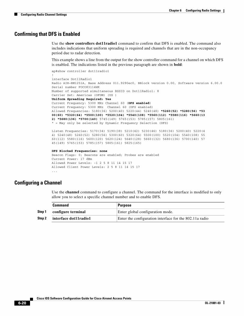
Confirming that DFS is Enabled
Use the show controllers dot11radio1 command to confirm that DFS is enabled. The command also includes indications that uniform spreading is required and channels that are in the non-occupancy period due to radar detection.
This example shows a line from the output for the show controller command for a channel on which DFS is enabled. The indications listed in the previous paragraph are shown in bold:
ap#show controller dot11radio1!interface Dot11Radio1Radio AIR-RM1251A, Base Address 011.9290ec0, BBlock version 0.00, Software version 6.00.0Serial number FOCO83114WKNumber of supported simultaneous BSSID on Dot11Radio1: 8Carrier Set: Americas (OFDM) (US )Uniform Spreading Required: YesCurrent Frequency: 5300 MHz Channel 60 (DFS enabled)Current Frequency: 5300 MHz Channel 60 (DFS enabled)Allowed Frequencies: 5180(36) 5200(40) 5220(44) 5240(48) *5260(52) *5280(56) *5300(60) *5320(64) *5500(100) *5520(104) *5540(108) *5560(112) *5580(116) *5660(132) *5680(136) *5700(140) 5745(149) 5765(153) 5785(157) 5805(161)* = May only be selected by Dynamic Frequency Selection (DFS)
Listen Frequencies: 5170(34) 5190(38) 5210(42) 5230(46) 5180(36) 5200(40) 5220(44) 5240(48) 5260(52) 5280(56) 5300(60) 5320(64) 5500(100) 5520(104) 5540(108) 5560(112) 5580(116) 5600(120) 5620(124) 5640(128) 5660(132) 5680(136) 5700(140) 5745(149) 5765(153) 5785(157) 5805(161) 5825(165)
DFS Blocked Frequencies: noneBeacon Flags: 0; Beacons are enabled; Probes are enabledCurrent Power: 17 dBmAllowed Power Levels: -1 2 5 8 11 14 15 17Allowed Client Power Levels: 2 5 8 11 14 15 17...
Configuring a Channel
Use the channel command to configure a channel. The command for the interface is modified to only allow you to select a specific channel number and to enable DFS.
Command Purpose
Step 1 configure terminal Enter global configuration mode.
Step 2 interface dot11radio1 Enter the configuration interface for the 802.11a radio
6-20Cisco IOS Software Configuration Guide for Cisco Aironet Access Points
OL-21881-03
Chapter 6 Configuring Radio SettingsConfiguring Radio Channel Settings
The following example configures the 5 GHz radio to use DFS:
ap#configure terminalap(config)#interface dot11radio1ap(config-if)#channel dfs ap(config-if)#
Blocking Channels from DFS Selection
If your regulatory domain limits the channels that you can use in specific locations--for example, indoors or outdoors--you can block groups of channels to prevent the access point from selecting them when DFS is enabled. Use this configuration interface command to block groups of channels from DFS selection:
[no] dfs band [1] [2] [3] [4] block
The 1, 2, 3, and 4 options designate blocks of channels:
• 1—Specifies frequencies 5.150 to 5.250 GHz. This group of frequencies is also known as the UNII-1 band.
• 2—Specifies frequencies 5.250 to 5.350 GHz. This group of frequencies is also known as the UNII-2 band.
• 3—Specifies frequencies 5.470 to 5.725 GHz.
• 4—Specifies frequencies 5.725 to 5.825 GHz. This group of frequencies is also known as the UNII-3 band.
This example shows how to prevent the access point from selecting frequencies 5.150 to 5.350 GHz during DFS:
ap(config-if)# dfs band 1 2 block
This example shows how to unblock frequencies 5.150 to 5.350 for DFS:
ap(config-if)# no dfs band 1 2 block
Step 3 channel {number | dfs} | dfs band <1 - 4>
For number, enter one of the following channels: 36, 40, 44, 48, 149, 153, 157, 161, 5180, 5200, 5220, 5240, 5745, 5765, 5785, or 5805. This channel list varies depending on the radio.
Enter dfs and one of the following frequency bands to use dynamic frequency selection on the selected channel:
1—5.150 to 5.250 GHz
2—5.250 to 5.350 Ghz
3—5.470 to 5.725 GHz
4—5.725 to 5.825 GHz
If you attempt to configure a channel that may only be selected by dfs, the following message appears:
This channel number/frequency can only be used by Dynamic Frequency Selection (DFS)
Step 4 end Return to the privileged EXEC mode.
Step 5 show running-config Verify your entries
Step 6 copy running-config startup-config (Optional) Save your entries to the configuration file.
Command Purpose
6-21Cisco IOS Software Configuration Guide for Cisco Aironet Access Points
OL-21881-03
Chapter 6 Configuring Radio SettingsConfiguring Location-Based Services
This example shows how to unblock all frequencies for DFS:
ap(config-if)# no dfs band block
Setting the 802.11n Guard IntervalThe 802.11n guard interval is the period in nanoseconds between packets. Two settings are available: short (400ns) and long (800ns).
Beginning in privileged EXEC mode, follow these steps to set the 802.11n guard interval.
Configuring Location-Based ServicesThis section describes how to configure location-based services using the access point CLI. As with other access point features, you can use a WLSE on your network to configure LBS on multiple access points. LBS settings do not appear on the access point GUI in this release.
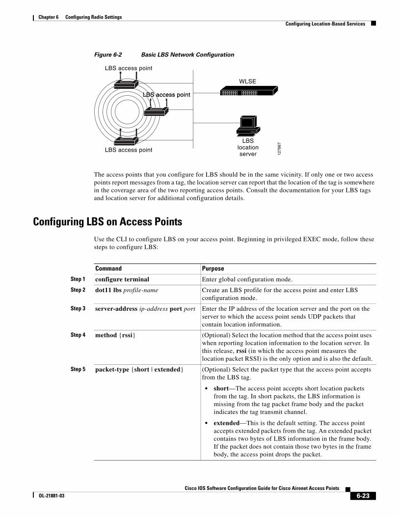
Understanding Location-Based ServicesWe recommend that you configure a minimum of three access points for LBS. When you configure location-based services (LBS) on your access points, the access points monitor location packets sent by LBS positioning tags attached to assets that you want to track. When an access point receives a positioning packet, it measures the received signal strength indication (RSSI) and creates a UDP packet that contains the RSSI value and the time that the location packet was received. The access point forwards the UDP packets to a location server. The location server calculates the LBS tag position based on the location information that it receives from the LBS-enabled access points. If your network has a WLSE, the location server can query the WLSE for the status of LBS-enabled access points. Figure 6-2 shows the basic parts of an LBS-enabled network.
Command Purpose
Step 1 configure terminal Enter global configuration mode.
Step 2 interface dot11radio {0 | 1} Enter interface configuration mode for the radio interface.
The 802.11n 2.4-GHz radio is radio 0
The 802.11n 5-GHz radio is radio 1.
Step 3 guard-interval {any | long} Enter a guard interval.
• any allows either the short (400ns) or long (800ns) guard interval.
• long allows only the long (800ns) guard interval.
Step 4 end Return to privileged EXEC mode.
Step 5 copy running-config startup-config
(Optional) Save your entries in the configuration file.
6-22Cisco IOS Software Configuration Guide for Cisco Aironet Access Points
OL-21881-03
Chapter 6 Configuring Radio SettingsConfiguring Location-Based Services
Figure 6-2 Basic LBS Network Configuration
The access points that you configure for LBS should be in the same vicinity. If only one or two access points report messages from a tag, the location server can report that the location of the tag is somewhere in the coverage area of the two reporting access points. Consult the documentation for your LBS tags and location server for additional configuration details.
Configuring LBS on Access PointsUse the CLI to configure LBS on your access point. Beginning in privileged EXEC mode, follow these steps to configure LBS:
LBS access point
LBS access point
WLSE
LBSlocationserver 12
7867
LBS access pointLBS access point
Command Purpose
Step 1 configure terminal Enter global configuration mode.
Step 2 dot11 lbs profile-name Create an LBS profile for the access point and enter LBS configuration mode.
Step 3 server-address ip-address port port Enter the IP address of the location server and the port on the server to which the access point sends UDP packets that contain location information.
Step 4 method {rssi} (Optional) Select the location method that the access point uses when reporting location information to the location server. In this release, rssi (in which the access point measures the location packet RSSI) is the only option and is also the default.
Step 5 packet-type {short | extended} (Optional) Select the packet type that the access point accepts from the LBS tag.
• short—The access point accepts short location packets from the tag. In short packets, the LBS information is missing from the tag packet frame body and the packet indicates the tag transmit channel.
• extended—This is the default setting. The access point accepts extended packets from the tag. An extended packet contains two bytes of LBS information in the frame body. If the packet does not contain those two bytes in the frame body, the access point drops the packet.
6-23Cisco IOS Software Configuration Guide for Cisco Aironet Access Points
OL-21881-03
Chapter 6 Configuring Radio SettingsEnabling and Disabling World Mode
In this example, the profile southside is enabled on the access point 802.11g radio:
ap# configure terminalap(config)# dot11 lbs southsideap(dot11-lbs)# server-address 10.91.105.90 port 1066ap(dot11-lbs)# interface dot11 0ap(dot11-lbs)# exit
Enabling and Disabling World ModeYou can configure the wireless device to support 802.11d world mode, Cisco legacy world mode, or world mode roaming. When you enable world mode, the wireless device adds channel carrier set information to its beacon. Client devices with world mode enabled receive the carrier set information and adjust their settings automatically. For example, a client device used primarily in Japan could rely on world mode to adjust its channel and power settings automatically when it travels to Italy and joins a network there. Cisco client devices running firmware version 5.30.17 or later detect whether the wireless device is using 802.11d or Cisco legacy world mode and automatically use world mode that matches the mode used by the wireless device.
You can also configure world mode to be always on. In this configuration, the access point essentially roams between countries changing its settings as required.
World mode is disabled by default.
Beginning in privileged EXEC mode, follow these steps to enable world mode:
Step 6 channel-match (Optional) Specifies that the LBS packet sent by the tag must match the radio channel on which the access point receives the packet. If the channel used by the tag and the channel used by the access point do not match, the access point drops the packet. Channel match is enabled by default.
Step 7 multicast-address mac-address (Optional) Specifies the multicast address that the tag uses when it sends LBS packets. The default multicast address is 01:40:96:00:00:10.
Step 8 interface dot11 { 0 | 1 } Specify the radio interface on which this LBS profile is enabled. The 2.4-GHz radio is radio 0, and the 5-GHz radio is radio 1. The profile remains inactive until you enter this command.
Step 9 exit Return to global configuration mode.
Command Purpose
Command Purpose
Step 1 configure terminal Enter global configuration mode.
Step 2 interface dot11radio {0 | 1} Enter interface configuration mode for the radio interface.
6-24Cisco IOS Software Configuration Guide for Cisco Aironet Access Points
OL-21881-03
Chapter 6 Configuring Radio SettingsDisabling and Enabling Short Radio Preambles
Use the no form of the command to disable world mode.
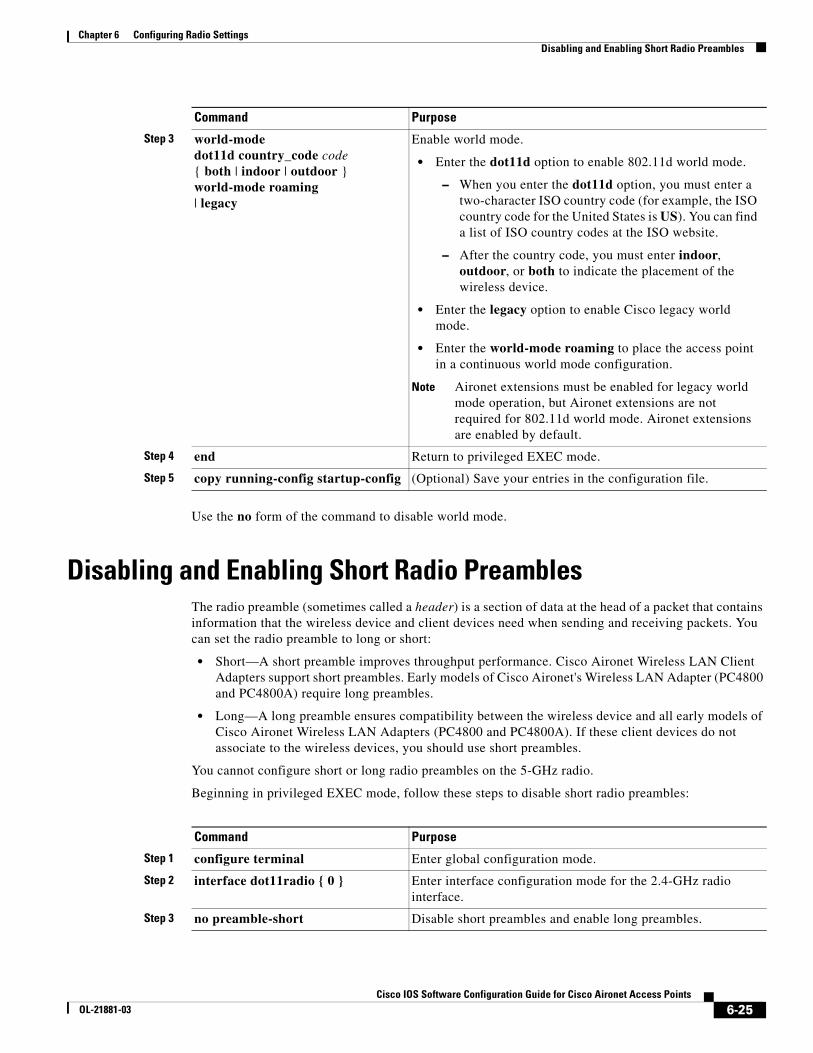
Disabling and Enabling Short Radio PreamblesThe radio preamble (sometimes called a header) is a section of data at the head of a packet that contains information that the wireless device and client devices need when sending and receiving packets. You can set the radio preamble to long or short:
• Short—A short preamble improves throughput performance. Cisco Aironet Wireless LAN Client Adapters support short preambles. Early models of Cisco Aironet's Wireless LAN Adapter (PC4800 and PC4800A) require long preambles.
• Long—A long preamble ensures compatibility between the wireless device and all early models of Cisco Aironet Wireless LAN Adapters (PC4800 and PC4800A). If these client devices do not associate to the wireless devices, you should use short preambles.
You cannot configure short or long radio preambles on the 5-GHz radio.
Beginning in privileged EXEC mode, follow these steps to disable short radio preambles:
Step 3 world-mode dot11d country_code code { both | indoor | outdoor } world-mode roaming| legacy
Enable world mode.
• Enter the dot11d option to enable 802.11d world mode.
– When you enter the dot11d option, you must enter a two-character ISO country code (for example, the ISO country code for the United States is US). You can find a list of ISO country codes at the ISO website.
– After the country code, you must enter indoor, outdoor, or both to indicate the placement of the wireless device.
• Enter the legacy option to enable Cisco legacy world mode.
• Enter the world-mode roaming to place the access point in a continuous world mode configuration.
Note Aironet extensions must be enabled for legacy world mode operation, but Aironet extensions are not required for 802.11d world mode. Aironet extensions are enabled by default.
Step 4 end Return to privileged EXEC mode.
Step 5 copy running-config startup-config (Optional) Save your entries in the configuration file.
Command Purpose
Command Purpose
Step 1 configure terminal Enter global configuration mode.
Step 2 interface dot11radio { 0 } Enter interface configuration mode for the 2.4-GHz radio interface.
Step 3 no preamble-short Disable short preambles and enable long preambles.
6-25Cisco IOS Software Configuration Guide for Cisco Aironet Access Points
OL-21881-03
Chapter 6 Configuring Radio SettingsConfiguring Transmit and Receive Antennas
Short preambles are enabled by default. Use the preamble-short command to enable short preambles if they are disabled.
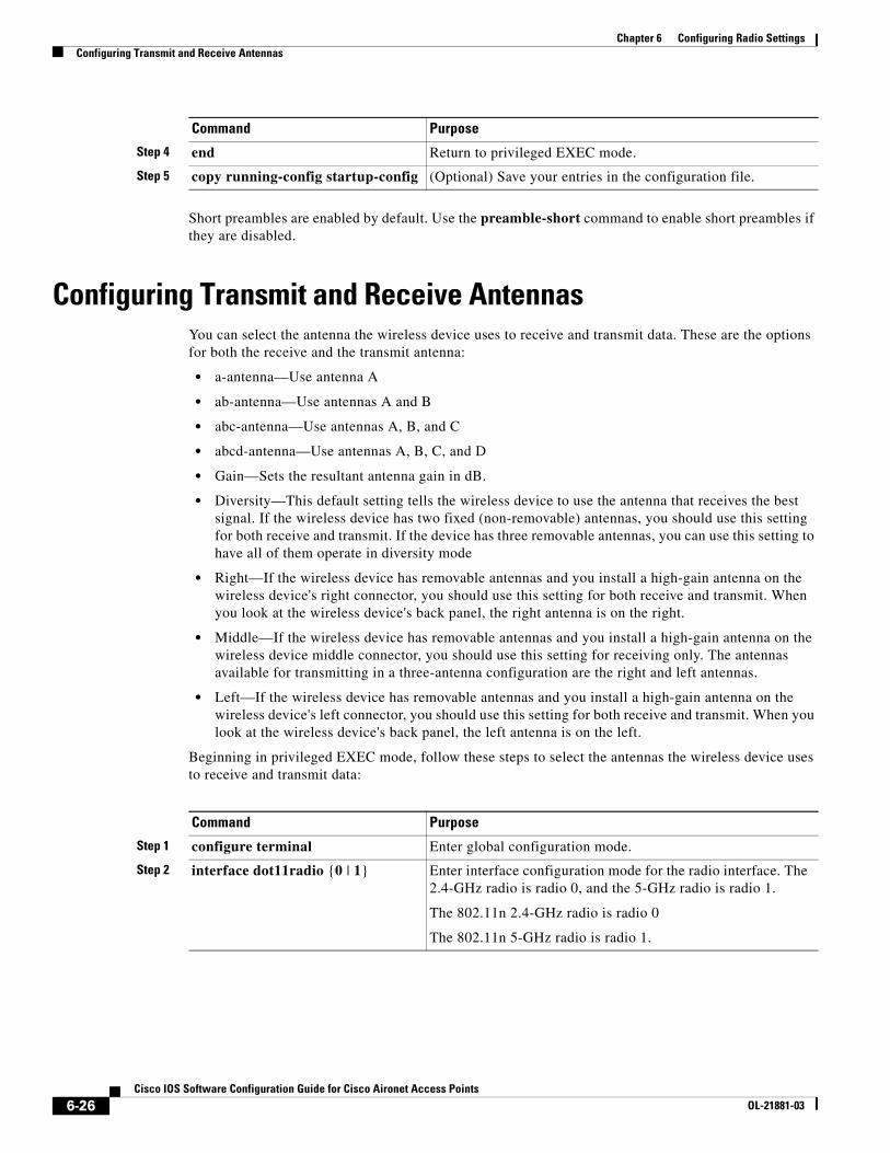
Configuring Transmit and Receive AntennasYou can select the antenna the wireless device uses to receive and transmit data. These are the options for both the receive and the transmit antenna:
• a-antenna—Use antenna A
• ab-antenna—Use antennas A and B
• abc-antenna—Use antennas A, B, and C
• abcd-antenna—Use antennas A, B, C, and D
• Gain—Sets the resultant antenna gain in dB.
• Diversity—This default setting tells the wireless device to use the antenna that receives the best signal. If the wireless device has two fixed (non-removable) antennas, you should use this setting for both receive and transmit. If the device has three removable antennas, you can use this setting to have all of them operate in diversity mode
• Right—If the wireless device has removable antennas and you install a high-gain antenna on the wireless device's right connector, you should use this setting for both receive and transmit. When you look at the wireless device's back panel, the right antenna is on the right.
• Middle—If the wireless device has removable antennas and you install a high-gain antenna on the wireless device middle connector, you should use this setting for receiving only. The antennas available for transmitting in a three-antenna configuration are the right and left antennas.
• Left—If the wireless device has removable antennas and you install a high-gain antenna on the wireless device's left connector, you should use this setting for both receive and transmit. When you look at the wireless device's back panel, the left antenna is on the left.
Beginning in privileged EXEC mode, follow these steps to select the antennas the wireless device uses to receive and transmit data:
Step 4 end Return to privileged EXEC mode.
Step 5 copy running-config startup-config (Optional) Save your entries in the configuration file.
Command Purpose
Command Purpose
Step 1 configure terminal Enter global configuration mode.
Step 2 interface dot11radio {0 | 1} Enter interface configuration mode for the radio interface. The 2.4-GHz radio is radio 0, and the 5-GHz radio is radio 1.
The 802.11n 2.4-GHz radio is radio 0
The 802.11n 5-GHz radio is radio 1.
6-26Cisco IOS Software Configuration Guide for Cisco Aironet Access Points
OL-21881-03
Chapter 6 Configuring Radio SettingsEnabling and Disabling Gratuitous Probe Response
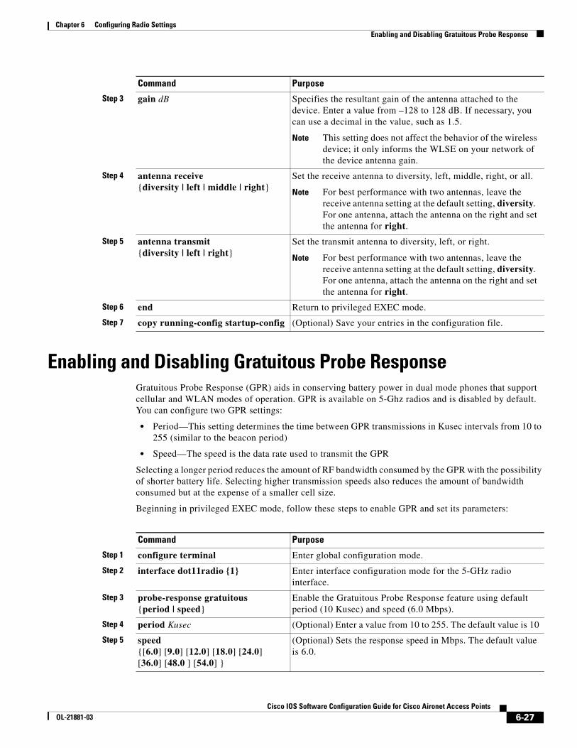
Enabling and Disabling Gratuitous Probe ResponseGratuitous Probe Response (GPR) aids in conserving battery power in dual mode phones that support cellular and WLAN modes of operation. GPR is available on 5-Ghz radios and is disabled by default. You can configure two GPR settings:
• Period—This setting determines the time between GPR transmissions in Kusec intervals from 10 to 255 (similar to the beacon period)
• Speed—The speed is the data rate used to transmit the GPR
Selecting a longer period reduces the amount of RF bandwidth consumed by the GPR with the possibility of shorter battery life. Selecting higher transmission speeds also reduces the amount of bandwidth consumed but at the expense of a smaller cell size.
Beginning in privileged EXEC mode, follow these steps to enable GPR and set its parameters:
Step 3 gain dB Specifies the resultant gain of the antenna attached to the device. Enter a value from –128 to 128 dB. If necessary, you can use a decimal in the value, such as 1.5.
Note This setting does not affect the behavior of the wireless device; it only informs the WLSE on your network of the device antenna gain.
Step 4 antenna receive{diversity | left | middle | right}
Set the receive antenna to diversity, left, middle, right, or all.
Note For best performance with two antennas, leave the receive antenna setting at the default setting, diversity. For one antenna, attach the antenna on the right and set the antenna for right.
Step 5 antenna transmit{diversity | left | right}
Set the transmit antenna to diversity, left, or right.
Note For best performance with two antennas, leave the receive antenna setting at the default setting, diversity. For one antenna, attach the antenna on the right and set the antenna for right.
Step 6 end Return to privileged EXEC mode.
Step 7 copy running-config startup-config (Optional) Save your entries in the configuration file.
Command Purpose
Command Purpose
Step 1 configure terminal Enter global configuration mode.
Step 2 interface dot11radio {1} Enter interface configuration mode for the 5-GHz radio interface.
Step 3 probe-response gratuitous {period | speed}
Enable the Gratuitous Probe Response feature using default period (10 Kusec) and speed (6.0 Mbps).
Step 4 period Kusec (Optional) Enter a value from 10 to 255. The default value is 10
Step 5 speed {[6.0] [9.0] [12.0] [18.0] [24.0] [36.0] [48.0 ] [54.0] }
(Optional) Sets the response speed in Mbps. The default value is 6.0.
6-27Cisco IOS Software Configuration Guide for Cisco Aironet Access Points
OL-21881-03
Chapter 6 Configuring Radio SettingsDisabling and Enabling Aironet Extensions
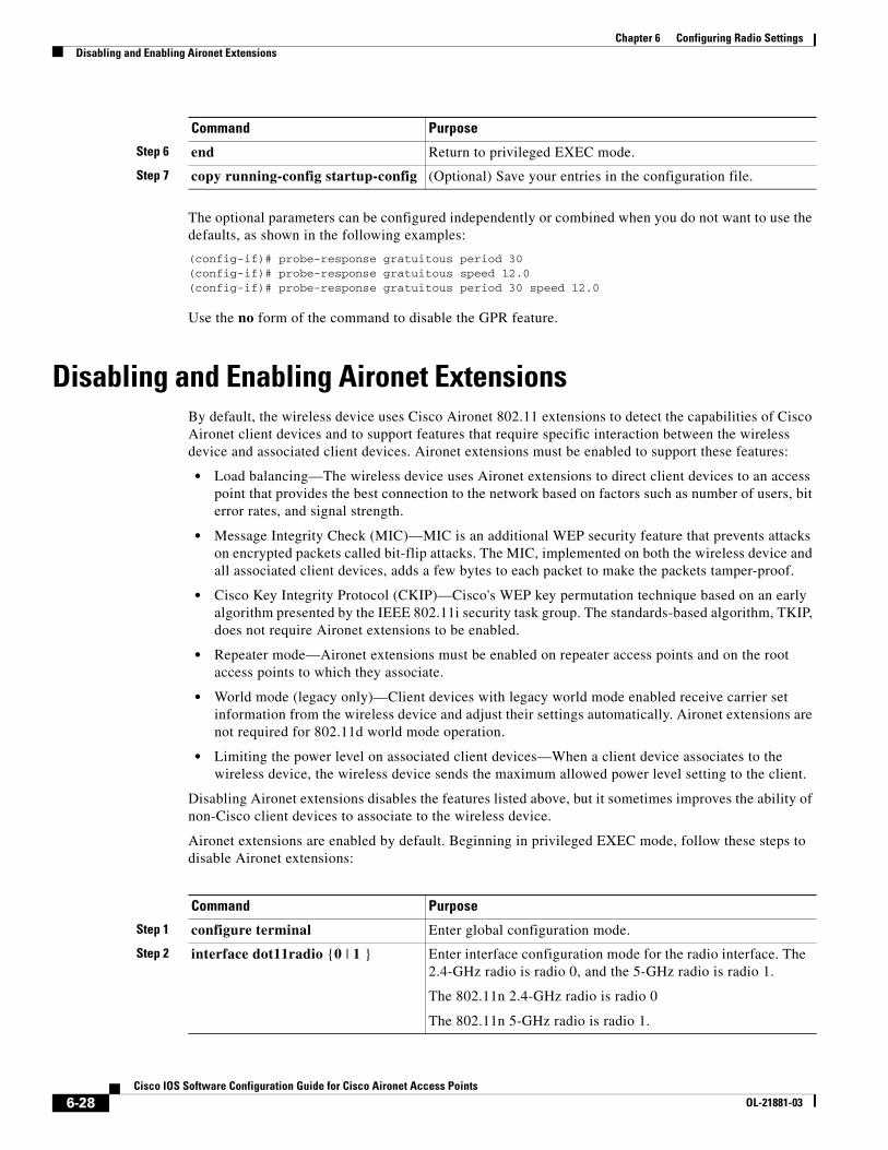
The optional parameters can be configured independently or combined when you do not want to use the defaults, as shown in the following examples:
(config-if)# probe-response gratuitous period 30(config-if)# probe-response gratuitous speed 12.0(config-if)# probe-response gratuitous period 30 speed 12.0
Use the no form of the command to disable the GPR feature.
Disabling and Enabling Aironet ExtensionsBy default, the wireless device uses Cisco Aironet 802.11 extensions to detect the capabilities of Cisco Aironet client devices and to support features that require specific interaction between the wireless device and associated client devices. Aironet extensions must be enabled to support these features:
• Load balancing—The wireless device uses Aironet extensions to direct client devices to an access point that provides the best connection to the network based on factors such as number of users, bit error rates, and signal strength.
• Message Integrity Check (MIC)—MIC is an additional WEP security feature that prevents attacks on encrypted packets called bit-flip attacks. The MIC, implemented on both the wireless device and all associated client devices, adds a few bytes to each packet to make the packets tamper-proof.
• Cisco Key Integrity Protocol (CKIP)—Cisco's WEP key permutation technique based on an early algorithm presented by the IEEE 802.11i security task group. The standards-based algorithm, TKIP, does not require Aironet extensions to be enabled.
• Repeater mode—Aironet extensions must be enabled on repeater access points and on the root access points to which they associate.
• World mode (legacy only)—Client devices with legacy world mode enabled receive carrier set information from the wireless device and adjust their settings automatically. Aironet extensions are not required for 802.11d world mode operation.
• Limiting the power level on associated client devices—When a client device associates to the wireless device, the wireless device sends the maximum allowed power level setting to the client.
Disabling Aironet extensions disables the features listed above, but it sometimes improves the ability of non-Cisco client devices to associate to the wireless device.
Aironet extensions are enabled by default. Beginning in privileged EXEC mode, follow these steps to disable Aironet extensions:
Step 6 end Return to privileged EXEC mode.
Step 7 copy running-config startup-config (Optional) Save your entries in the configuration file.
Command Purpose
Command Purpose
Step 1 configure terminal Enter global configuration mode.
Step 2 interface dot11radio {0 | 1 } Enter interface configuration mode for the radio interface. The 2.4-GHz radio is radio 0, and the 5-GHz radio is radio 1.
The 802.11n 2.4-GHz radio is radio 0
The 802.11n 5-GHz radio is radio 1.
6-28Cisco IOS Software Configuration Guide for Cisco Aironet Access Points
OL-21881-03
Chapter 6 Configuring Radio SettingsConfiguring the Ethernet Encapsulation Transformation Method
Use the dot11 extension aironet command to enable Aironet extensions if they are disabled.
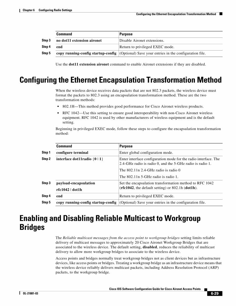
Configuring the Ethernet Encapsulation Transformation MethodWhen the wireless device receives data packets that are not 802.3 packets, the wireless device must format the packets to 802.3 using an encapsulation transformation method. These are the two transformation methods:
• 802.1H—This method provides good performance for Cisco Aironet wireless products.
• RFC 1042—Use this setting to ensure good interoperability with non-Cisco Aironet wireless equipment. RFC 1042 is used by other manufacturers of wireless equipment and is the default setting.
Beginning in privileged EXEC mode, follow these steps to configure the encapsulation transformation method:
Enabling and Disabling Reliable Multicast to Workgroup Bridges
The Reliable multicast messages from the access point to workgroup bridges setting limits reliable delivery of multicast messages to approximately 20 Cisco Aironet Workgroup Bridges that are associated to the wireless device. The default setting, disabled, reduces the reliability of multicast delivery to allow more workgroup bridges to associate to the wireless device.
Access points and bridges normally treat workgroup bridges not as client devices but as infrastructure devices, like access points or bridges. Treating a workgroup bridge as an infrastructure device means that the wireless device reliably delivers multicast packets, including Address Resolution Protocol (ARP) packets, to the workgroup bridge.
Step 3 no dot11 extension aironet Disable Aironet extensions.
Step 4 end Return to privileged EXEC mode.
Step 5 copy running-config startup-config (Optional) Save your entries in the configuration file.
Command Purpose
Command Purpose
Step 1 configure terminal Enter global configuration mode.
Step 2 interface dot11radio {0 | 1} Enter interface configuration mode for the radio interface. The 2.4-GHz radio is radio 0, and the 5-GHz radio is radio 1.
The 802.11n 2.4-GHz radio is radio 0
The 802.11n 5-GHz radio is radio 1.
Step 3 payload-encapsulation
rfc1042 | dot1h
Set the encapsulation transformation method to RFC 1042 (rfc1042, the default setting) or 802.1h (dot1h).
Step 4 end Return to privileged EXEC mode.
Step 5 copy running-config startup-config (Optional) Save your entries in the configuration file.
6-29Cisco IOS Software Configuration Guide for Cisco Aironet Access Points
OL-21881-03

Chapter 6 Configuring Radio SettingsEnabling and Disabling Public Secure Packet Forwarding
The performance cost of reliable multicast delivery—duplication of each multicast packet sent to each workgroup bridge—limits the number of infrastructure devices, including workgroup bridges, that can associate to the wireless device. To increase beyond 20 the number of workgroup bridges that can maintain a radio link to the wireless device, the wireless device must reduce the delivery reliability of multicast packets to workgroup bridges. With reduced reliability, the wireless device cannot confirm whether multicast packets reach the intended workgroup bridge, so workgroup bridges at the edge of the wireless device's coverage area might lose IP connectivity. When you treat workgroup bridges as client devices, you increase performance but reduce reliability.
Note This feature is best suited for use with stationary workgroup bridges. Mobile workgroup bridges might encounter spots in the wireless device's coverage area where they do not receive multicast packets and lose communication with the wireless device even though they are still associated to it.
A Cisco Aironet Workgroup Bridge provides a wireless LAN connection for up to eight Ethernet-enabled devices.
This feature is not supported on the 5-GHz radio.
Beginning in privileged EXEC mode, follow these steps to configure the encapsulation transformation method:
Use the no form of the command to disable reliable multicast messages to workgroup bridges.
Enabling and Disabling Public Secure Packet ForwardingPublic Secure Packet Forwarding (PSPF) prevents client devices associated to an access point from inadvertently sharing files or communicating with other client devices associated to the access point. It provides Internet access to client devices without providing other capabilities of a LAN. This feature is useful for public wireless networks like those installed in airports or on college campuses.
Note To prevent communication between clients associated to different access points, you must set up protected ports on the switch to which the wireless devices are connected. See the “Configuring Protected Ports” section on page 6-31 for instructions on setting up protected ports.
Command Purpose
Step 1 configure terminal Enter global configuration mode.
Step 2 interface dot11radio { 0 } Enter interface configuration mode for the 2.4-GHz radio interface.
Step 3 infrastructure-client Enable reliable multicast messages to workgroup bridges.
Step 4 end Return to privileged EXEC mode.
Step 5 copy running-config startup-config (Optional) Save your entries in the configuration file.
6-30Cisco IOS Software Configuration Guide for Cisco Aironet Access Points
OL-21881-03
Chapter 6 Configuring Radio SettingsEnabling and Disabling Public Secure Packet Forwarding
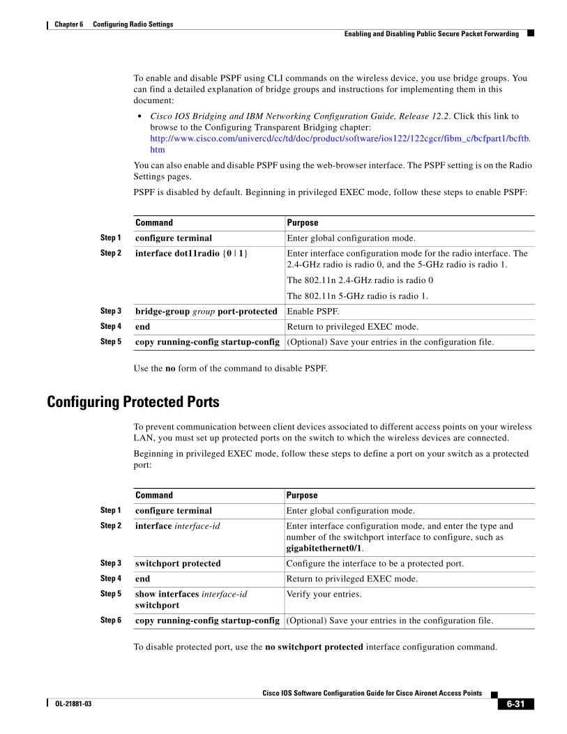
To enable and disable PSPF using CLI commands on the wireless device, you use bridge groups. You can find a detailed explanation of bridge groups and instructions for implementing them in this document:
• Cisco IOS Bridging and IBM Networking Configuration Guide, Release 12.2. Click this link to browse to the Configuring Transparent Bridging chapter: http://www.cisco.com/univercd/cc/td/doc/product/software/ios122/122cgcr/fibm_c/bcfpart1/bcftb.htm
You can also enable and disable PSPF using the web-browser interface. The PSPF setting is on the Radio Settings pages.
PSPF is disabled by default. Beginning in privileged EXEC mode, follow these steps to enable PSPF:
Use the no form of the command to disable PSPF.
Configuring Protected PortsTo prevent communication between client devices associated to different access points on your wireless LAN, you must set up protected ports on the switch to which the wireless devices are connected.
Beginning in privileged EXEC mode, follow these steps to define a port on your switch as a protected port:
To disable protected port, use the no switchport protected interface configuration command.
Command Purpose
Step 1 configure terminal Enter global configuration mode.
Step 2 interface dot11radio {0 | 1} Enter interface configuration mode for the radio interface. The 2.4-GHz radio is radio 0, and the 5-GHz radio is radio 1.
The 802.11n 2.4-GHz radio is radio 0
The 802.11n 5-GHz radio is radio 1.
Step 3 bridge-group group port-protected Enable PSPF.
Step 4 end Return to privileged EXEC mode.
Step 5 copy running-config startup-config (Optional) Save your entries in the configuration file.
Command Purpose
Step 1 configure terminal Enter global configuration mode.
Step 2 interface interface-id Enter interface configuration mode, and enter the type and number of the switchport interface to configure, such as gigabitethernet0/1.
Step 3 switchport protected Configure the interface to be a protected port.
Step 4 end Return to privileged EXEC mode.
Step 5 show interfaces interface-id switchport
Verify your entries.
Step 6 copy running-config startup-config (Optional) Save your entries in the configuration file.
6-31Cisco IOS Software Configuration Guide for Cisco Aironet Access Points
OL-21881-03
Chapter 6 Configuring Radio SettingsConfiguring the Beacon Period and the DTIM
For detailed information on protected ports and port blocking, refer to the “Configuring Port-Based Traffic Control” chapter in the Catalyst 3550 Multilayer Switch Software Configuration Guide, 12.1(12c)EA1. Click this link to browse to that guide:
http://www.cisco.com/en/US/products/hw/switches/ps646/products_configuration_guide_book09186a008011591c.html
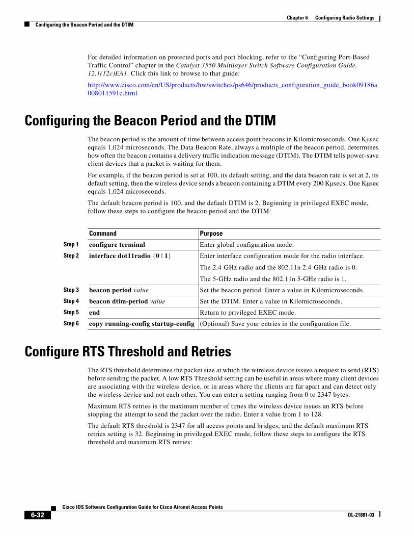
Configuring the Beacon Period and the DTIMThe beacon period is the amount of time between access point beacons in Kilomicroseconds. One Kµsec equals 1,024 microseconds. The Data Beacon Rate, always a multiple of the beacon period, determines how often the beacon contains a delivery traffic indication message (DTIM). The DTIM tells power-save client devices that a packet is waiting for them.
For example, if the beacon period is set at 100, its default setting, and the data beacon rate is set at 2, its default setting, then the wireless device sends a beacon containing a DTIM every 200 Kµsecs. One Kµsec equals 1,024 microseconds.
The default beacon period is 100, and the default DTIM is 2. Beginning in privileged EXEC mode, follow these steps to configure the beacon period and the DTIM:
Configure RTS Threshold and RetriesThe RTS threshold determines the packet size at which the wireless device issues a request to send (RTS) before sending the packet. A low RTS Threshold setting can be useful in areas where many client devices are associating with the wireless device, or in areas where the clients are far apart and can detect only the wireless device and not each other. You can enter a setting ranging from 0 to 2347 bytes.
Maximum RTS retries is the maximum number of times the wireless device issues an RTS before stopping the attempt to send the packet over the radio. Enter a value from 1 to 128.
The default RTS threshold is 2347 for all access points and bridges, and the default maximum RTS retries setting is 32. Beginning in privileged EXEC mode, follow these steps to configure the RTS threshold and maximum RTS retries:
Command Purpose
Step 1 configure terminal Enter global configuration mode.
Step 2 interface dot11radio {0 | 1} Enter interface configuration mode for the radio interface.
The 2.4-GHz radio and the 802.11n 2.4-GHz radio is 0.
The 5-GHz radio and the 802.11n 5-GHz radio is 1.
Step 3 beacon period value Set the beacon period. Enter a value in Kilomicroseconds.
Step 4 beacon dtim-period value Set the DTIM. Enter a value in Kilomicroseconds.
Step 5 end Return to privileged EXEC mode.
Step 6 copy running-config startup-config (Optional) Save your entries in the configuration file.
6-32Cisco IOS Software Configuration Guide for Cisco Aironet Access Points
OL-21881-03
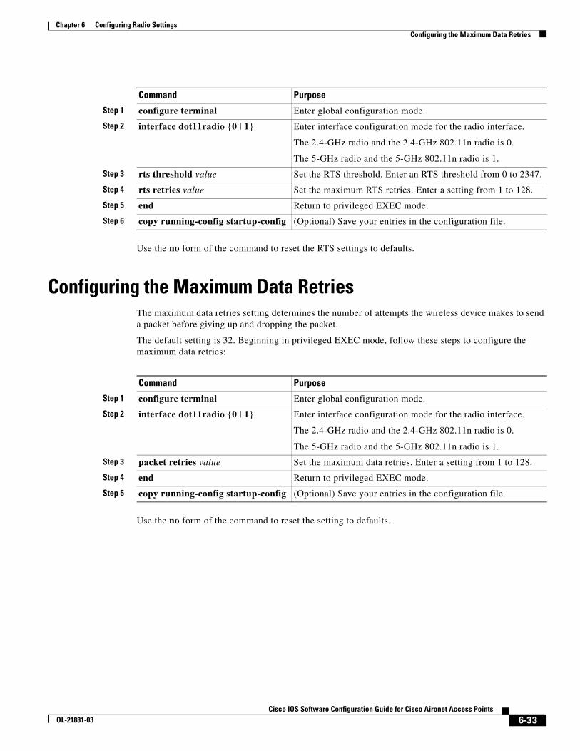
Chapter 6 Configuring Radio SettingsConfiguring the Maximum Data Retries
Use the no form of the command to reset the RTS settings to defaults.
Configuring the Maximum Data RetriesThe maximum data retries setting determines the number of attempts the wireless device makes to send a packet before giving up and dropping the packet.
The default setting is 32. Beginning in privileged EXEC mode, follow these steps to configure the maximum data retries:
Use the no form of the command to reset the setting to defaults.
Command Purpose
Step 1 configure terminal Enter global configuration mode.
Step 2 interface dot11radio {0 | 1} Enter interface configuration mode for the radio interface.
The 2.4-GHz radio and the 2.4-GHz 802.11n radio is 0.
The 5-GHz radio and the 5-GHz 802.11n radio is 1.
Step 3 rts threshold value Set the RTS threshold. Enter an RTS threshold from 0 to 2347.
Step 4 rts retries value Set the maximum RTS retries. Enter a setting from 1 to 128.
Step 5 end Return to privileged EXEC mode.
Step 6 copy running-config startup-config (Optional) Save your entries in the configuration file.
Command Purpose
Step 1 configure terminal Enter global configuration mode.
Step 2 interface dot11radio {0 | 1} Enter interface configuration mode for the radio interface.
The 2.4-GHz radio and the 2.4-GHz 802.11n radio is 0.
The 5-GHz radio and the 5-GHz 802.11n radio is 1.
Step 3 packet retries value Set the maximum data retries. Enter a setting from 1 to 128.
Step 4 end Return to privileged EXEC mode.
Step 5 copy running-config startup-config (Optional) Save your entries in the configuration file.
6-33Cisco IOS Software Configuration Guide for Cisco Aironet Access Points
OL-21881-03
Chapter 6 Configuring Radio SettingsConfiguring the Fragmentation Threshold
Configuring the Fragmentation ThresholdThe fragmentation threshold determines the size at which packets are fragmented (sent as several pieces instead of as one block). Use a low setting in areas where communication is poor or where there is a great deal of radio interference.
The default setting is 2338 bytes. Beginning in privileged EXEC mode, follow these steps to configure the fragmentation threshold:
Use the no form of the command to reset the setting to defaults.
Enabling Short Slot Time for 802.11g RadiosYou can increase throughput on the 802.11g, 2.4-GHz radio by enabling short slot time. Reducing the slot time from the standard 20 microseconds to the 9-microsecond short slot time decreases the overall backoff, which increases throughput. Backoff, which is a multiple of the slot time, is the random length of time that a station waits before sending a packet on the LAN.
Many 802.11g radios support short slot time, but some do not. When you enable short slot time, the wireless device uses the short slot time only when all clients associated to the 802.11g, 2.4-GHz radio support short slot time.
Short slot time is supported only on the 802.11g, 2.4-GHz radio. Short slot time is disabled by default.
In radio interface mode, enter this command to enable short slot time:
ap(config-if)# short-slot-time
Enter no short-slot-time to disable short slot time.
Command Purpose
Step 1 configure terminal Enter global configuration mode.
Step 2 interface dot11radio {0 | 1} Enter interface configuration mode for the radio interface.
The 2.4-GHz radio and the 2.4-GHz 802.11n radio is 0.
The 5-GHz radio and the 5-GHz 802.11n radio is 1.
Step 3 fragment-threshold value Set the fragmentation threshold. Enter a setting from 256 to 2346 bytes for the 2.4-GHz radio. Enter a setting from 256 to 2346 bytes for the 5-GHz radio.
Step 4 end Return to privileged EXEC mode.
Step 5 copy running-config startup-config (Optional) Save your entries in the configuration file.
6-34Cisco IOS Software Configuration Guide for Cisco Aironet Access Points
OL-21881-03
Chapter 6 Configuring Radio SettingsPerforming a Carrier Busy Test
Performing a Carrier Busy TestYou can perform a carrier busy test to check the radio activity on wireless channels. During the carrier busy test, the wireless device drops all associations with wireless networking devices for 4 seconds while it conducts the carrier test and then displays the test results.
In privileged EXEC mode, enter this command to perform a carrier busy test:
dot11 interface-number carrier busy
For interface-number, enter dot11radio 0 to run the test on the 2.4-GHz radio, or enter dot11radio 1 to run the test on the 5-GHz radio.
Use the show dot11 carrier busy command to re-display the carrier busy test results.
Configuring VoIP Packet HandlingYou can improve the quality of VoIP packet handling per radio on access points by enhancing 802.11 MAC behavior for lower latency for the CoS 5 (Video) and CoS 6 (Voice) user priorities.
Follow these steps to configure VoIP packet handling on an access point:
Step 1 Using a browser, log in to the access point.
Step 2 Click Services in the task menu on the left side of the web-browser interface.
Step 3 When the list of Services expands, click Stream.
The Stream page appears.
Step 4 Click the tab for the radio to configure.
Step 5 For both CoS 5 (Video) and CoS 6 (Voice) user priorities, choose Low Latency from the Packet Handling drop-down menu and enter a value for maximum retries for packet discard in the corresponding field.
The default value for maximum retries is 3 for the Low Latency setting (Figure 6-3). This value indicates how many times the access point will try to retrieve a lost packet before discarding it.
Note You may also configure the CoS 4 (Controlled Load) user priority and its maximum retries value.
Step 6 Click Apply.
6-35Cisco IOS Software Configuration Guide for Cisco Aironet Access Points
OL-21881-03
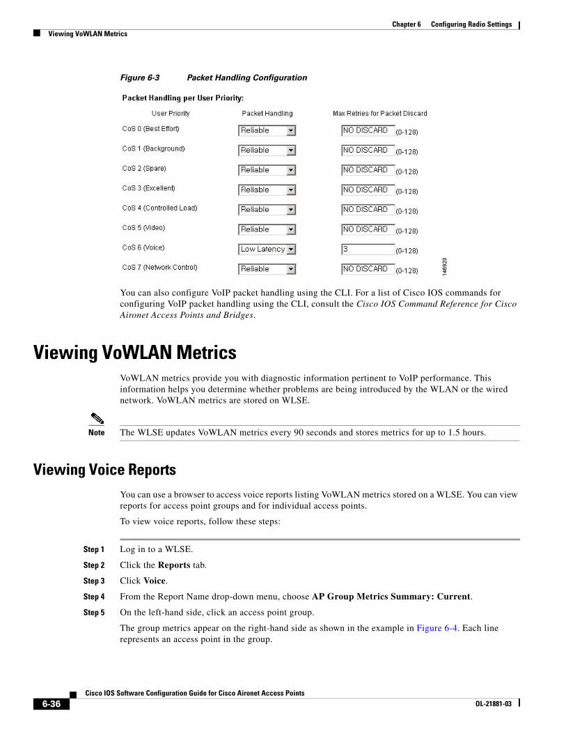
Chapter 6 Configuring Radio SettingsViewing VoWLAN Metrics
Figure 6-3 Packet Handling Configuration
You can also configure VoIP packet handling using the CLI. For a list of Cisco IOS commands for configuring VoIP packet handling using the CLI, consult the Cisco IOS Command Reference for Cisco Aironet Access Points and Bridges.
Viewing VoWLAN MetricsVoWLAN metrics provide you with diagnostic information pertinent to VoIP performance. This information helps you determine whether problems are being introduced by the WLAN or the wired network. VoWLAN metrics are stored on WLSE.
Note The WLSE updates VoWLAN metrics every 90 seconds and stores metrics for up to 1.5 hours.
Viewing Voice ReportsYou can use a browser to access voice reports listing VoWLAN metrics stored on a WLSE. You can view reports for access point groups and for individual access points.
To view voice reports, follow these steps:
Step 1 Log in to a WLSE.
Step 2 Click the Reports tab.
Step 3 Click Voice.
Step 4 From the Report Name drop-down menu, choose AP Group Metrics Summary: Current.
Step 5 On the left-hand side, click an access point group.
The group metrics appear on the right-hand side as shown in the example in Figure 6-4. Each line represents an access point in the group.
6-36Cisco IOS Software Configuration Guide for Cisco Aironet Access Points
OL-21881-03
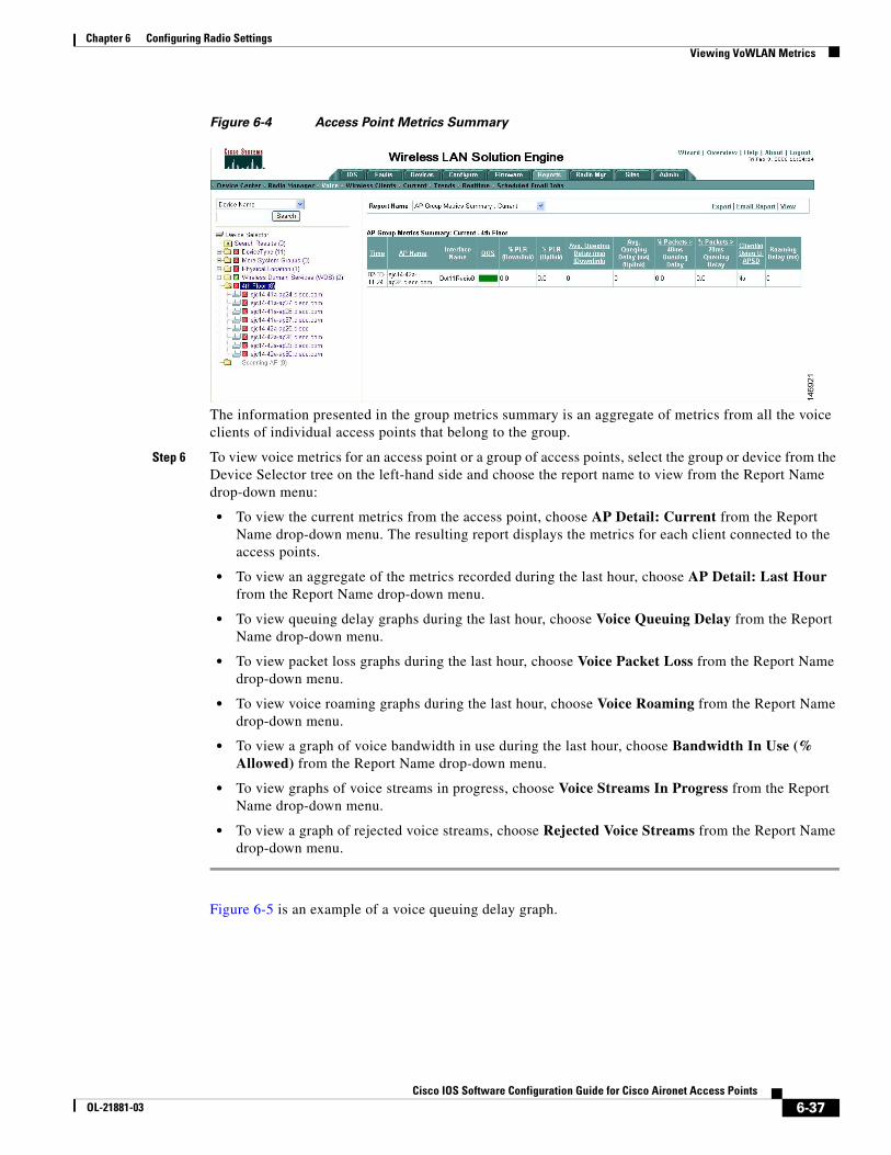
Chapter 6 Configuring Radio SettingsViewing VoWLAN Metrics
Figure 6-4 Access Point Metrics Summary
The information presented in the group metrics summary is an aggregate of metrics from all the voice clients of individual access points that belong to the group.
Step 6 To view voice metrics for an access point or a group of access points, select the group or device from the Device Selector tree on the left-hand side and choose the report name to view from the Report Name drop-down menu:
• To view the current metrics from the access point, choose AP Detail: Current from the Report Name drop-down menu. The resulting report displays the metrics for each client connected to the access points.
• To view an aggregate of the metrics recorded during the last hour, choose AP Detail: Last Hour from the Report Name drop-down menu.
• To view queuing delay graphs during the last hour, choose Voice Queuing Delay from the Report Name drop-down menu.
• To view packet loss graphs during the last hour, choose Voice Packet Loss from the Report Name drop-down menu.
• To view voice roaming graphs during the last hour, choose Voice Roaming from the Report Name drop-down menu.
• To view a graph of voice bandwidth in use during the last hour, choose Bandwidth In Use (% Allowed) from the Report Name drop-down menu.
• To view graphs of voice streams in progress, choose Voice Streams In Progress from the Report Name drop-down menu.
• To view a graph of rejected voice streams, choose Rejected Voice Streams from the Report Name drop-down menu.
Figure 6-5 is an example of a voice queuing delay graph.
6-37Cisco IOS Software Configuration Guide for Cisco Aironet Access Points
OL-21881-03
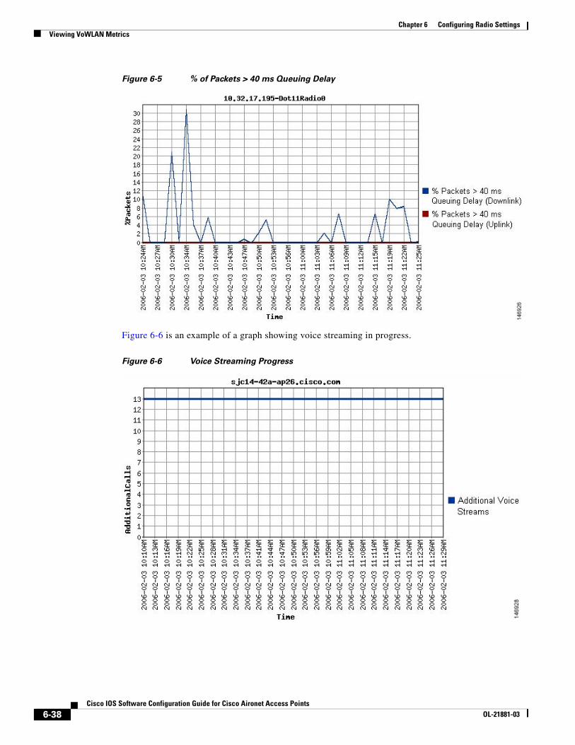
Chapter 6 Configuring Radio SettingsViewing VoWLAN Metrics
Figure 6-5 % of Packets > 40 ms Queuing Delay
Figure 6-6 is an example of a graph showing voice streaming in progress.
Figure 6-6 Voice Streaming Progress
6-38Cisco IOS Software Configuration Guide for Cisco Aironet Access Points
OL-21881-03
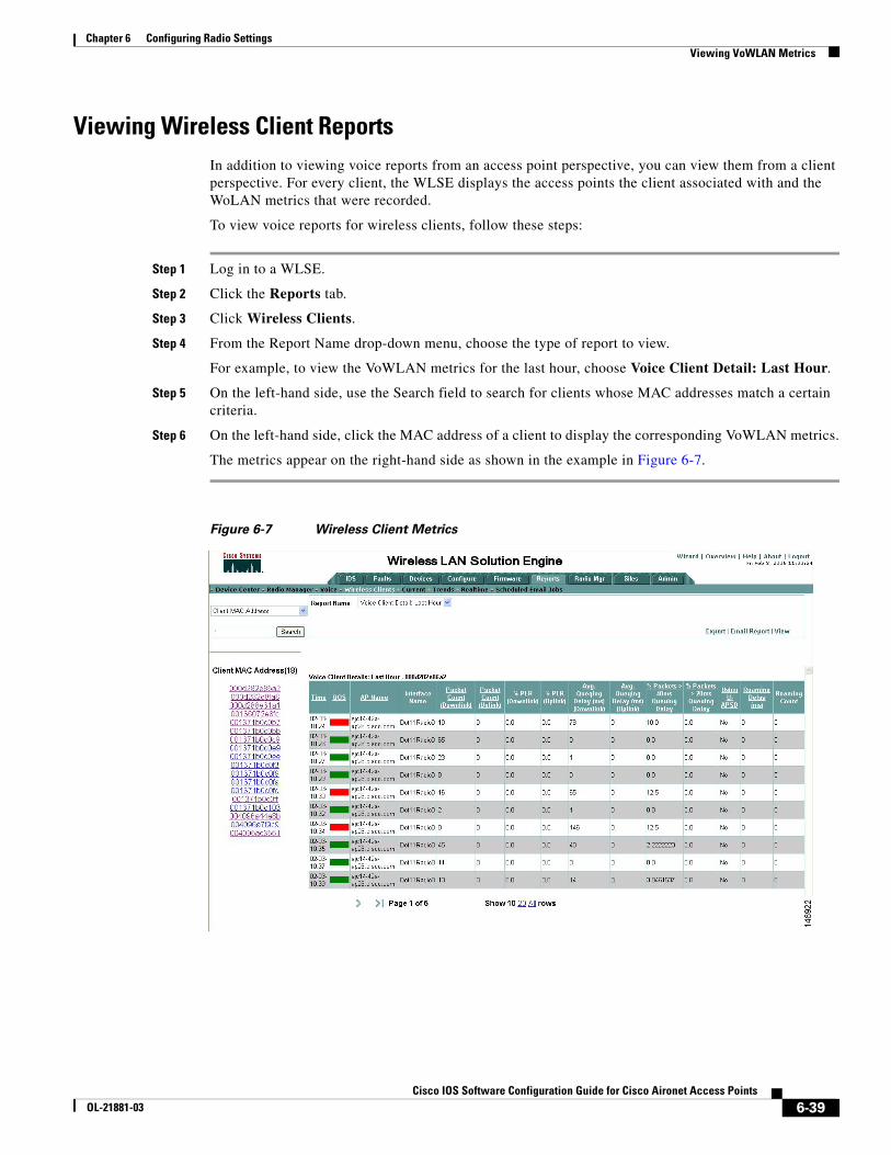
Chapter 6 Configuring Radio SettingsViewing VoWLAN Metrics
Viewing Wireless Client ReportsIn addition to viewing voice reports from an access point perspective, you can view them from a client perspective. For every client, the WLSE displays the access points the client associated with and the WoLAN metrics that were recorded.
To view voice reports for wireless clients, follow these steps:
Step 1 Log in to a WLSE.
Step 2 Click the Reports tab.
Step 3 Click Wireless Clients.
Step 4 From the Report Name drop-down menu, choose the type of report to view.
For example, to view the VoWLAN metrics for the last hour, choose Voice Client Detail: Last Hour.
Step 5 On the left-hand side, use the Search field to search for clients whose MAC addresses match a certain criteria.
Step 6 On the left-hand side, click the MAC address of a client to display the corresponding VoWLAN metrics.
The metrics appear on the right-hand side as shown in the example in Figure 6-7.
Figure 6-7 Wireless Client Metrics
6-39Cisco IOS Software Configuration Guide for Cisco Aironet Access Points
OL-21881-03
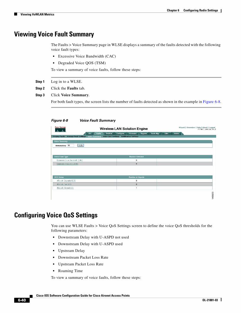
Chapter 6 Configuring Radio SettingsViewing VoWLAN Metrics
Viewing Voice Fault SummaryThe Faults > Voice Summary page in WLSE displays a summary of the faults detected with the following voice fault types:
• Excessive Voice Bandwidth (CAC)
• Degraded Voice QOS (TSM)
To view a summary of voice faults, follow these steps:
Step 1 Log in to a WLSE.
Step 2 Click the Faults tab.
Step 3 Click Voice Summary.
For both fault types, the screen lists the number of faults detected as shown in the example in Figure 6-8.
Figure 6-8 Voice Fault Summary
Configuring Voice QoS SettingsYou can use WLSE Faults > Voice QoS Settings screen to define the voice QoS thresholds for the following parameters:
• Downstream Delay with U-ASPD not used
• Downstream Delay with U-ASPD used
• Upstream Delay
• Downstream Packet Loss Rate
• Upstream Packet Loss Rate
• Roaming Time
To view a summary of voice faults, follow these steps:
6-40Cisco IOS Software Configuration Guide for Cisco Aironet Access Points
OL-21881-03
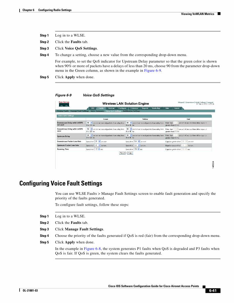
Chapter 6 Configuring Radio SettingsViewing VoWLAN Metrics
Step 1 Log in to a WLSE.
Step 2 Click the Faults tab.
Step 3 Click Voice QoS Settings.
Step 4 To change a setting, choose a new value from the corresponding drop-down menu.
For example, to set the QoS indicator for Upstream Delay parameter so that the green color is shown when 90% or more of packets have a delays of less than 20 ms, choose 90 from the parameter drop-down menu in the Green column, as shown in the example in Figure 6-9.
Step 5 Click Apply when done.
Figure 6-9 Voice QoS Settings
Configuring Voice Fault SettingsYou can use WLSE Faults > Manage Fault Settings screen to enable fault generation and specify the priority of the faults generated.
To configure fault settings, follow these steps:
Step 1 Log in to a WLSE.
Step 2 Click the Faults tab.
Step 3 Click Manage Fault Settings.
Step 4 Choose the priority of the faults generated if QoS is red (fair) from the corresponding drop-down menu.
Step 5 Click Apply when done.
In the example in Figure 6-8, the system generates P1 faults when QoS is degraded and P3 faults when QoS is fair. If QoS is green, the system clears the faults generated.
6-41Cisco IOS Software Configuration Guide for Cisco Aironet Access Points
OL-21881-03
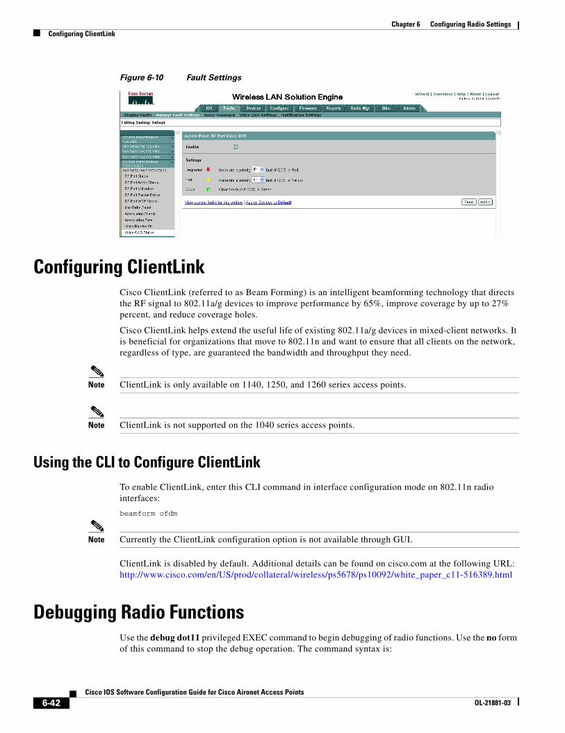
Chapter 6 Configuring Radio SettingsConfiguring ClientLink
Figure 6-10 Fault Settings
Configuring ClientLinkCisco ClientLink (referred to as Beam Forming) is an intelligent beamforming technology that directs the RF signal to 802.11a/g devices to improve performance by 65%, improve coverage by up to 27% percent, and reduce coverage holes.
Cisco ClientLink helps extend the useful life of existing 802.11a/g devices in mixed-client networks. It is beneficial for organizations that move to 802.11n and want to ensure that all clients on the network, regardless of type, are guaranteed the bandwidth and throughput they need.
Note ClientLink is only available on 1140, 1250, and 1260 series access points.
Note ClientLink is not supported on the 1040 series access points.
Using the CLI to Configure ClientLinkTo enable ClientLink, enter this CLI command in interface configuration mode on 802.11n radio interfaces:
beamform ofdm
Note Currently the ClientLink configuration option is not available through GUI.
ClientLink is disabled by default. Additional details can be found on cisco.com at the following URL: http://www.cisco.com/en/US/prod/collateral/wireless/ps5678/ps10092/white_paper_c11-516389.html
Debugging Radio FunctionsUse the debug dot11 privileged EXEC command to begin debugging of radio functions. Use the no form of this command to stop the debug operation. The command syntax is:
6-42Cisco IOS Software Configuration Guide for Cisco Aironet Access Points
OL-21881-03
Chapter 6 Configuring Radio SettingsDebugging Radio Functions
[no] debug dot11{events | packets | forwarding | mgmt | network-map | syslog | virtual-interface}
The syntax is described in Table 6-5.
Table 6-5 Syntax for debug dot11 Command
This example shows how to begin debugging of all radio-related events:
AP# debug dot11 events
This example shows how to begin debugging of radio packets:
AP# debug dot11 packets
This example shows how to begin debugging of the radio system log:
AP# debug dot11 syslog
This example shows how to stop debugging of all radio related events:
AP# no debug dot11 events
Note Debugging not enabled is the default of the command.
Syntax Description
events Activates debugging of all radio related events
packets Activates debugging of radio packets received and transmitted
forwarding Activates debugging of radio forwarded packets
mgmt Activates debugging of radio access point management activity
network-map Activates debugging of radio association management network map
syslog Activates debugging of radio system log
virtual interface Activates debugging of radio virtual interfaces
6-43Cisco IOS Software Configuration Guide for Cisco Aironet Access Points
OL-21881-03

Chapter 6 Configuring Radio SettingsDebugging Radio Functions
6-44Cisco IOS Software Configuration Guide for Cisco Aironet Access Points
OL-21881-03


![Configuring Location Settings - Cisco · How to Configure Location Settings Configuring Location Settings (CLI) SUMMARY STEPS 1. configureterminal 2. locationplm{calibrating[multiband|uniband]|clientburst_interval](https://img.pdfslide.net/doc/110x75/5f6ae998a6f9b643442436e9/configuring-location-settings-cisco-how-to-configure-location-settings-configuring.jpg)