Embed Size (px)
Citation preview
JYOTHISHMATHI INSTITUTE OF
TECHNOLOGY AND SCIENCE,NUSTULAPUR, KARRIMNAGAR-27
CONIC SECTIONS
Prepared by
K. Mahesh
Asst. proff
Dept: mechanical
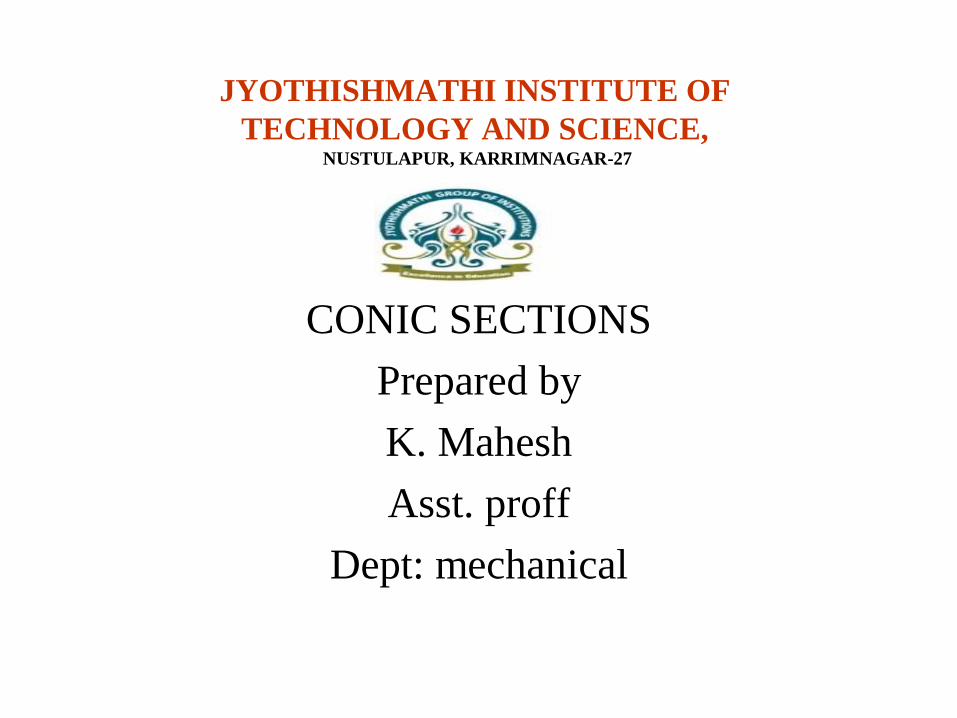
CONIC SECTIONSELLIPSE, PARABOLA AND HYPERBOLA ARE CALLED CONIC SECTIONS
BECAUSE THESE CURVES APPEAR ON THE SURFACE OF A CONE WHEN IT IS CUT BY SOME TYPICAL CUTTING PLANES.
Section Plane
Through Generators
Ellipse
Section Plane Parallel
to end generator.
Section Plane
Parallel to Axis.Hyperbola
1
2
3
4
5
6
7
8
9
10
BA
D
C
1
23
4
5
6
78
9
10
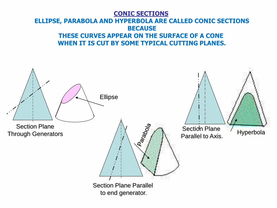
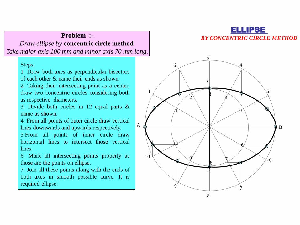
Steps:
1. Draw both axes as perpendicular bisectors
of each other & name their ends as shown.
2. Taking their intersecting point as a center,
draw two concentric circles considering both
as respective diameters.
3. Divide both circles in 12 equal parts &
name as shown.
4. From all points of outer circle draw vertical
lines downwards and upwards respectively.
5.From all points of inner circle draw
horizontal lines to intersect those vertical
lines.
6. Mark all intersecting points properly as
those are the points on ellipse.
7. Join all these points along with the ends of
both axes in smooth possible curve. It is
required ellipse.
Problem :-
Draw ellipse by concentric circle method.
Take major axis 100 mm and minor axis 70 mm long.
ELLIPSE BY CONCENTRIC CIRCLE METHOD
1
2
3
4
1
2
3
4
A B
C
D
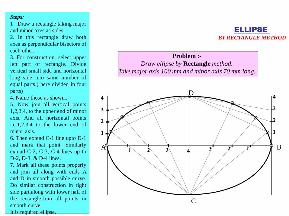
Problem :-
Draw ellipse by Rectangle method.
Take major axis 100 mm and minor axis 70 mm long.
Steps:
1 Draw a rectangle taking major
and minor axes as sides.
2. In this rectangle draw both
axes as perpendicular bisectors of
each other..
3. For construction, select upper
left part of rectangle. Divide
vertical small side and horizontal
long side into same number of
equal parts.( here divided in four
parts)
4. Name those as shown..
5. Now join all vertical points
1,2,3,4, to the upper end of minor
axis. And all horizontal points
i.e.1,2,3,4 to the lower end of
minor axis.
6. Then extend C-1 line upto D-1
and mark that point. Similarly
extend C-2, C-3, C-4 lines up to
D-2, D-3, & D-4 lines.
7. Mark all these points properly
and join all along with ends A
and D in smooth possible curve.
Do similar construction in right
side part.along with lower half of
the rectangle.Join all points in
smooth curve.
It is required ellipse.
ELLIPSE BY RECTANGLE METHOD
1
2
3
4
5
6
1 2 3 4 5 6
1
2
3
4
5
6
5 4 3 2 1
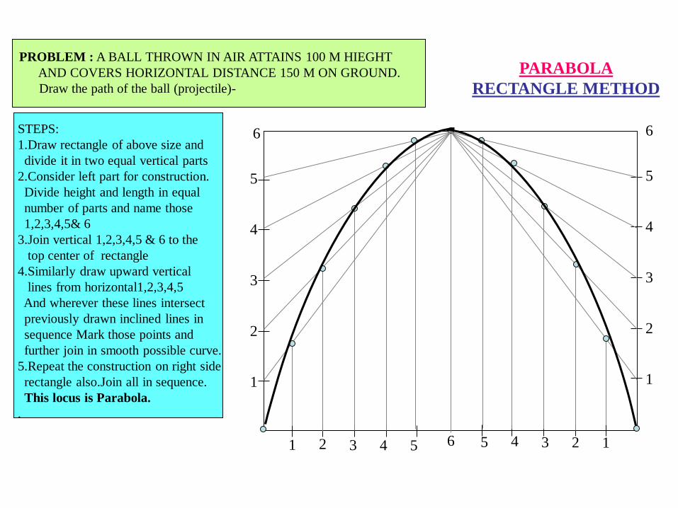
PARABOLA
RECTANGLE METHOD
PROBLEM : A BALL THROWN IN AIR ATTAINS 100 M HIEGHT
AND COVERS HORIZONTAL DISTANCE 150 M ON GROUND.
Draw the path of the ball (projectile)-
STEPS:
1.Draw rectangle of above size and
divide it in two equal vertical parts
2.Consider left part for construction.
Divide height and length in equal
number of parts and name those
1,2,3,4,5& 6
3.Join vertical 1,2,3,4,5 & 6 to the
top center of rectangle
4.Similarly draw upward vertical
lines from horizontal1,2,3,4,5
And wherever these lines intersect
previously drawn inclined lines in
sequence Mark those points and
further join in smooth possible curve.
5.Repeat the construction on right side
rectangle also.Join all in sequence.
This locus is Parabola.
.
C
A B
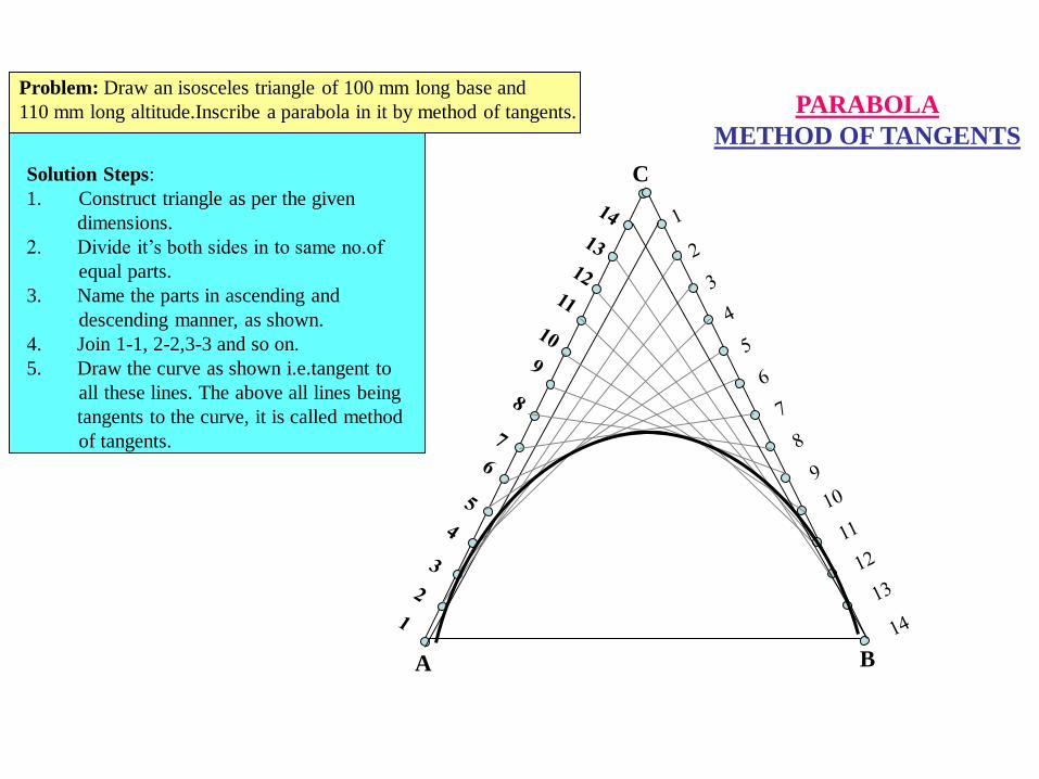
PARABOLA
METHOD OF TANGENTS
Problem: Draw an isosceles triangle of 100 mm long base and
110 mm long altitude.Inscribe a parabola in it by method of tangents.
Solution Steps:
1. Construct triangle as per the given
dimensions.
2. Divide it’s both sides in to same no.of
equal parts.
3. Name the parts in ascending and
descending manner, as shown.
4. Join 1-1, 2-2,3-3 and so on.
5. Draw the curve as shown i.e.tangent to
all these lines. The above all lines being
tangents to the curve, it is called method
of tangents.
P
O
40 mm
30 mm
1
2
3
12 1 2 3
1
2
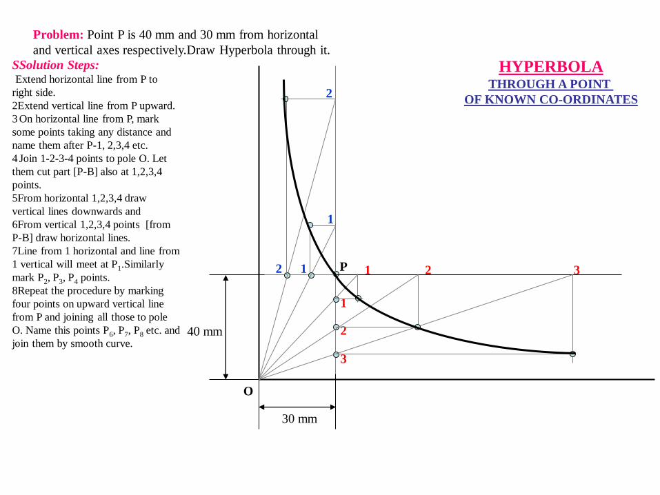
HYPERBOLATHROUGH A POINT
OF KNOWN CO-ORDINATES
SSolution Steps:Extend horizontal line from P to
right side.
2Extend vertical line from P upward.
3 On horizontal line from P, mark
some points taking any distance and
name them after P-1, 2,3,4 etc.
4 Join 1-2-3-4 points to pole O. Let
them cut part [P-B] also at 1,2,3,4
points.
5From horizontal 1,2,3,4 draw
vertical lines downwards and
6From vertical 1,2,3,4 points [from
P-B] draw horizontal lines.
7Line from 1 horizontal and line from
1 vertical will meet at P1.Similarly
mark P2, P3, P4 points.
8Repeat the procedure by marking
four points on upward vertical line
from P and joining all those to pole
O. Name this points P6, P7, P8 etc. and
join them by smooth curve.
Problem: Point P is 40 mm and 30 mm from horizontal
and vertical axes respectively.Draw Hyperbola through it.
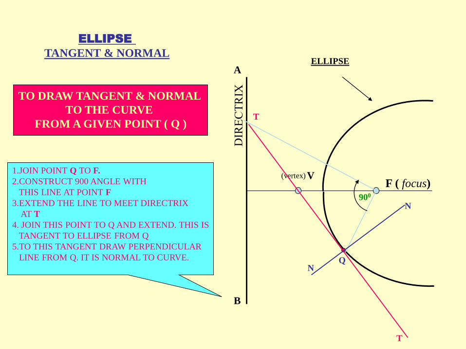
ELLIPSE
TANGENT & NORMAL
F ( focus)V
ELLIPSE
(vertex)
A
B
T
T
N
N
Q
900
TO DRAW TANGENT & NORMAL
TO THE CURVE
FROM A GIVEN POINT ( Q )
1.JOIN POINT Q TO F.
2.CONSTRUCT 900 ANGLE WITH
THIS LINE AT POINT F
3.EXTEND THE LINE TO MEET DIRECTRIX
AT T
4. JOIN THIS POINT TO Q AND EXTEND. THIS IS
TANGENT TO ELLIPSE FROM Q
5.TO THIS TANGENT DRAW PERPENDICULAR
LINE FROM Q. IT IS NORMAL TO CURVE.
A
B
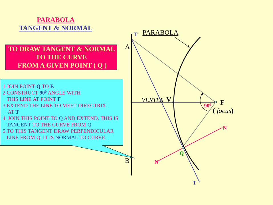
PARABOLA
VERTEX F
( focus)
V
Q
T
N
N
T
900
TO DRAW TANGENT & NORMAL
TO THE CURVE
FROM A GIVEN POINT ( Q )
1.JOIN POINT Q TO F.
2.CONSTRUCT 900 ANGLE WITH
THIS LINE AT POINT F
3.EXTEND THE LINE TO MEET DIRECTRIX
AT T
4. JOIN THIS POINT TO Q AND EXTEND. THIS IS
TANGENT TO THE CURVE FROM Q
5.TO THIS TANGENT DRAW PERPENDICULAR
LINE FROM Q. IT IS NORMAL TO CURVE.
PARABOLA
TANGENT & NORMAL
F ( focus)V
(vertex)
A
B
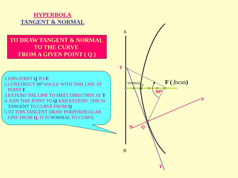
HYPERBOLA
TANGENT & NORMAL
QN
N
T
T
900
TO DRAW TANGENT & NORMAL
TO THE CURVE
FROM A GIVEN POINT ( Q )
1.JOIN POINT Q TO F.
2.CONSTRUCT 900 ANGLE WITH THIS LINE AT
POINT F
3.EXTEND THE LINE TO MEET DIRECTRIX AT T
4. JOIN THIS POINT TO Q AND EXTEND. THIS IS
TANGENT TO CURVE FROM Q
5.TO THIS TANGENT DRAW PERPENDICULAR
LINE FROM Q. IT IS NORMAL TO CURVE.
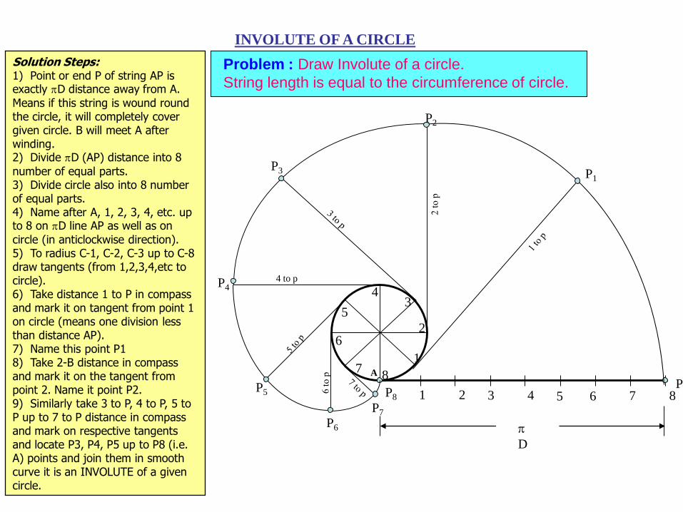
INVOLUTE OF A CIRCLE
Problem : Draw Involute of a circle.
String length is equal to the circumference of circle.
1 2 3 4 5 6 7 8P
P8
1
2
34
5
6
78
P3
P44 to p
P5
P7
P6
P2
P1
D
A
Solution Steps:1) Point or end P of string AP is exactly D distance away from A.
Means if this string is wound round the circle, it will completely cover given circle. B will meet A after winding.2) Divide D (AP) distance into 8
number of equal parts.3) Divide circle also into 8 number of equal parts.4) Name after A, 1, 2, 3, 4, etc. up to 8 on D line AP as well as on
circle (in anticlockwise direction).5) To radius C-1, C-2, C-3 up to C-8 draw tangents (from 1,2,3,4,etc to circle).6) Take distance 1 to P in compass and mark it on tangent from point 1 on circle (means one division less than distance AP).7) Name this point P1 8) Take 2-B distance in compass and mark it on the tangent from point 2. Name it point P2.9) Similarly take 3 to P, 4 to P, 5 to P up to 7 to P distance in compass and mark on respective tangents and locate P3, P4, P5 up to P8 (i.e. A) points and join them in smooth curve it is an INVOLUTE of a given circle.
C2
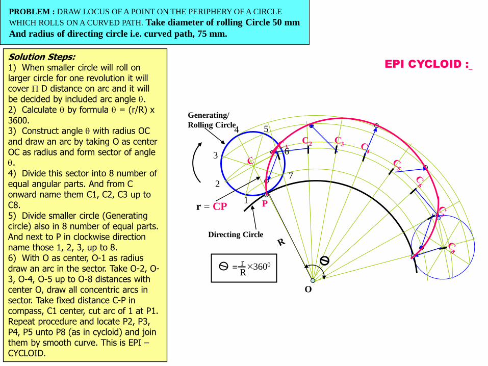
EPI CYCLOID :
P
O
r = CP
rR
3600=
1
2
3
4 5
6
7
Generating/
Rolling Circle
Directing Circle
Solution Steps:1) When smaller circle will roll on larger circle for one revolution it will cover D distance on arc and it will be decided by included arc angle .2) Calculate by formula = (r/R) x
3600.3) Construct angle with radius OC
and draw an arc by taking O as center OC as radius and form sector of angle .
4) Divide this sector into 8 number of equal angular parts. And from C onward name them C1, C2, C3 up to C8.5) Divide smaller circle (Generating circle) also in 8 number of equal parts. And next to P in clockwise direction name those 1, 2, 3, up to 8.6) With O as center, O-1 as radius draw an arc in the sector. Take O-2, O-3, O-4, O-5 up to O-8 distances with center O, draw all concentric arcs in sector. Take fixed distance C-P in compass, C1 center, cut arc of 1 at P1.Repeat procedure and locate P2, P3, P4, P5 unto P8 (as in cycloid) and join them by smooth curve. This is EPI –CYCLOID.
PROBLEM : DRAW LOCUS OF A POINT ON THE PERIPHERY OF A CIRCLE
WHICH ROLLS ON A CURVED PATH. Take diameter of rolling Circle 50 mm
And radius of directing circle i.e. curved path, 75 mm.
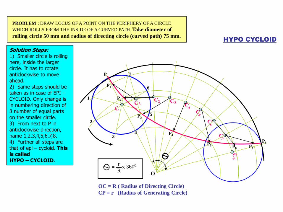
HYPO CYCLOID
P1
P2
P3
P4
P5 P6 P7
P8
P
1
2
3
6
5
7
4
O
OC = R ( Radius of Directing Circle)
CP = r (Radius of Generating Circle)
r
R3600=
PROBLEM : DRAW LOCUS OF A POINT ON THE PERIPHERY OF A CIRCLE
WHICH ROLLS FROM THE INSIDE OF A CURVED PATH. Take diameter of
rolling circle 50 mm and radius of directing circle (curved path) 75 mm.
Solution Steps:1) Smaller circle is rolling here, inside the larger circle. It has to rotate anticlockwise to move ahead.2) Same steps should be taken as in case of EPI –CYCLOID. Only change is in numbering direction of 8 number of equal parts on the smaller circle.3) From next to P in anticlockwise direction, name 1,2,3,4,5,6,7,8.4) Further all steps are that of epi – cycloid. This is calledHYPO – CYCLOID.
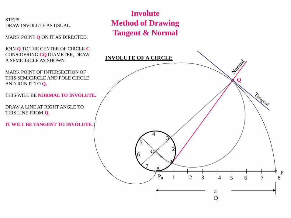
Q
Involute
Method of Drawing
Tangent & Normal
STEPS:
DRAW INVOLUTE AS USUAL.
MARK POINT Q ON IT AS DIRECTED.
JOIN Q TO THE CENTER OF CIRCLE C.
CONSIDERING CQ DIAMETER, DRAW
A SEMICIRCLE AS SHOWN.
MARK POINT OF INTERSECTION OF
THIS SEMICIRCLE AND POLE CIRCLE
AND JOIN IT TO Q.
THIS WILL BE NORMAL TO INVOLUTE.
DRAW A LINE AT RIGHT ANGLE TO
THIS LINE FROM Q.
IT WILL BE TANGENT TO INVOLUTE.
1 2 3 4 5 6 7 8P
P8
1
2
34
5
6
78
INVOLUTE OF A CIRCLE
D
C
Q
N
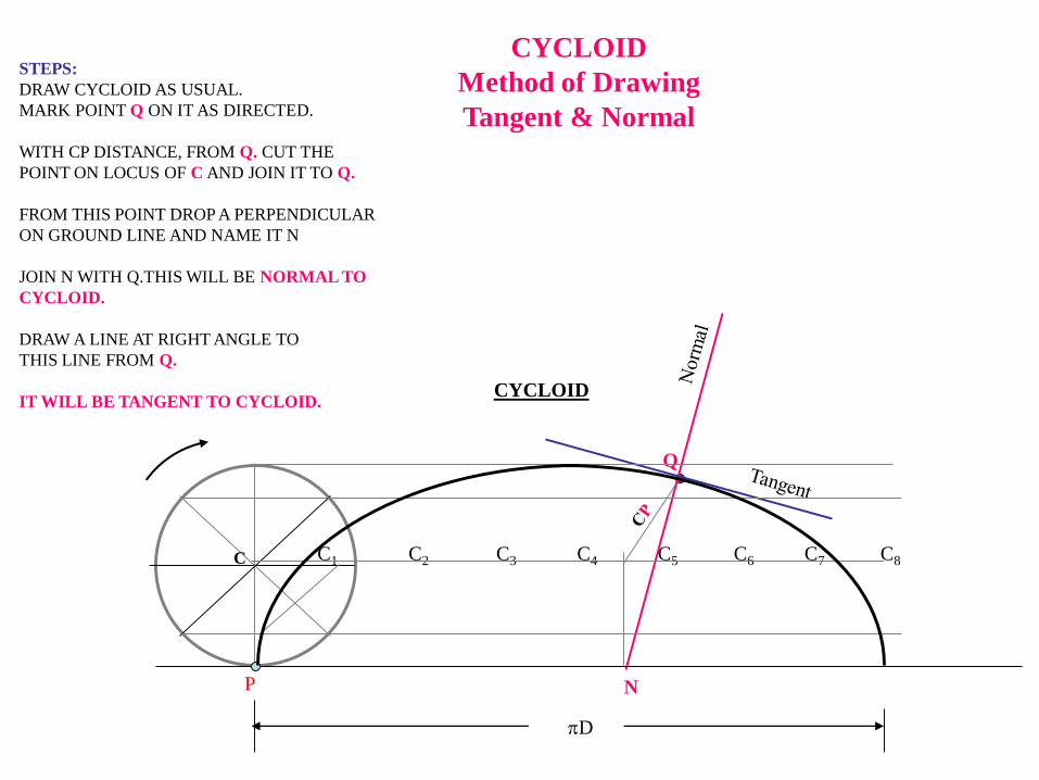
CYCLOID
Method of Drawing
Tangent & Normal
STEPS:
DRAW CYCLOID AS USUAL.
MARK POINT Q ON IT AS DIRECTED.
WITH CP DISTANCE, FROM Q. CUT THE
POINT ON LOCUS OF C AND JOIN IT TO Q.
FROM THIS POINT DROP A PERPENDICULAR
ON GROUND LINE AND NAME IT N
JOIN N WITH Q.THIS WILL BE NORMAL TO
CYCLOID.
DRAW A LINE AT RIGHT ANGLE TO
THIS LINE FROM Q.
IT WILL BE TANGENT TO CYCLOID.
P
C1 C2 C3 C4 C5 C6 C7 C8
D
CYCLOID
C
SCALES
Prepared by
K. Mahesh
Asst. proff
Dept: mechanical
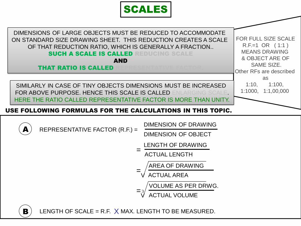
FOR FULL SIZE SCALE
R.F.=1 OR ( 1:1 )
MEANS DRAWING
& OBJECT ARE OF
SAME SIZE.
Other RFs are described
as
1:10, 1:100,
1:1000, 1:1,00,000
SCALES
DIMENSIONS OF LARGE OBJECTS MUST BE REDUCED TO ACCOMMODATE
ON STANDARD SIZE DRAWING SHEET. THIS REDUCTION CREATES A SCALE
OF THAT REDUCTION RATIO, WHICH IS GENERALLY A FRACTION..
SUCH A SCALE IS CALLED REDUCING SCALE
AND
THAT RATIO IS CALLED REPRESENTATIVE FACTOR.
SIMILARLY IN CASE OF TINY OBJECTS DIMENSIONS MUST BE INCREASED
FOR ABOVE PURPOSE. HENCE THIS SCALE IS CALLED ENLARGING SCALE.
HERE THE RATIO CALLED REPRESENTATIVE FACTOR IS MORE THAN UNITY.
REPRESENTATIVE FACTOR (R.F.) =
=
=
=
A
USE FOLLOWING FORMULAS FOR THE CALCULATIONS IN THIS TOPIC.
B LENGTH OF SCALE = R.F. MAX. LENGTH TO BE MEASURED.X
DIMENSION OF DRAWING
DIMENSION OF OBJECT
LENGTH OF DRAWING
ACTUAL LENGTH
AREA OF DRAWING
ACTUAL AREA
VOLUME AS PER DRWG.
ACTUAL VOLUME
V
V3
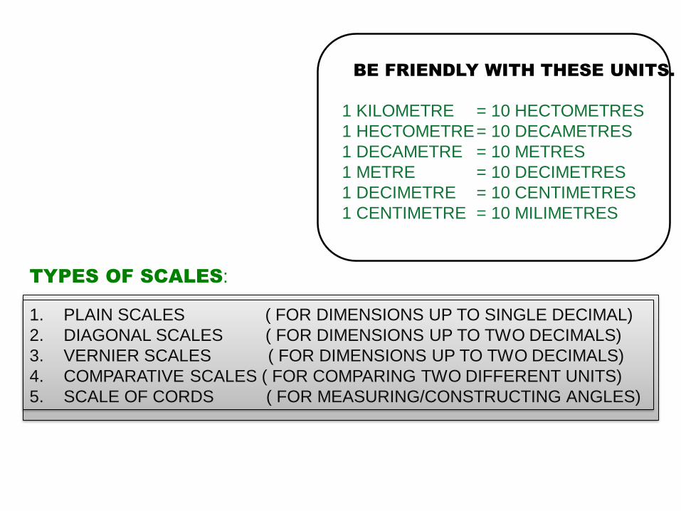
1. PLAIN SCALES ( FOR DIMENSIONS UP TO SINGLE DECIMAL)
2. DIAGONAL SCALES ( FOR DIMENSIONS UP TO TWO DECIMALS)
3. VERNIER SCALES ( FOR DIMENSIONS UP TO TWO DECIMALS)
4. COMPARATIVE SCALES ( FOR COMPARING TWO DIFFERENT UNITS)
5. SCALE OF CORDS ( FOR MEASURING/CONSTRUCTING ANGLES)
TYPES OF SCALES:
= 10 HECTOMETRES
= 10 DECAMETRES
= 10 METRES
= 10 DECIMETRES
= 10 CENTIMETRES
= 10 MILIMETRES
1 KILOMETRE
1 HECTOMETRE
1 DECAMETRE
1 METRE
1 DECIMETRE
1 CENTIMETRE
BE FRIENDLY WITH THESE UNITS.
0 1 2 3 4 510
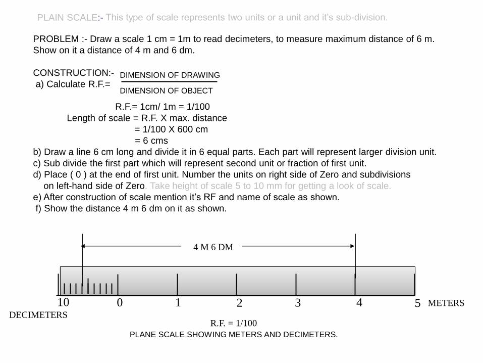
PLAIN SCALE:- This type of scale represents two units or a unit and it’s sub-division.
METERS
DECIMETERSR.F. = 1/100
4 M 6 DM
PLANE SCALE SHOWING METERS AND DECIMETERS.
PROBLEM :- Draw a scale 1 cm = 1m to read decimeters, to measure maximum distance of 6 m.
Show on it a distance of 4 m and 6 dm.
CONSTRUCTION:-
a) Calculate R.F.=
R.F.= 1cm/ 1m = 1/100
Length of scale = R.F. X max. distance
= 1/100 X 600 cm
= 6 cms
b) Draw a line 6 cm long and divide it in 6 equal parts. Each part will represent larger division unit.
c) Sub divide the first part which will represent second unit or fraction of first unit.
d) Place ( 0 ) at the end of first unit. Number the units on right side of Zero and subdivisions
on left-hand side of Zero. Take height of scale 5 to 10 mm for getting a look of scale.
e) After construction of scale mention it’s RF and name of scale as shown.
f) Show the distance 4 m 6 dm on it as shown.
DIMENSION OF DRAWING
DIMENSION OF OBJECT
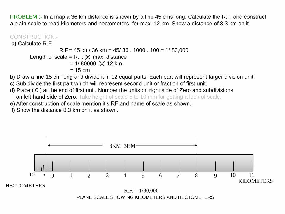
PROBLEM :- In a map a 36 km distance is shown by a line 45 cms long. Calculate the R.F. and construct
a plain scale to read kilometers and hectometers, for max. 12 km. Show a distance of 8.3 km on it.
CONSTRUCTION:-
a) Calculate R.F.
R.F.= 45 cm/ 36 km = 45/ 36 . 1000 . 100 = 1/ 80,000
Length of scale = R.F. max. distance
= 1/ 80000 12 km
= 15 cm
b) Draw a line 15 cm long and divide it in 12 equal parts. Each part will represent larger division unit.
c) Sub divide the first part which will represent second unit or fraction of first unit.
d) Place ( 0 ) at the end of first unit. Number the units on right side of Zero and subdivisions
on left-hand side of Zero. Take height of scale 5 to 10 mm for getting a look of scale.
e) After construction of scale mention it’s RF and name of scale as shown.
f) Show the distance 8.3 km on it as shown.
KILOMETERSHECTOMETERS
8KM 3HM
R.F. = 1/80,000
PLANE SCALE SHOWING KILOMETERS AND HECTOMETERS
0 1 2 3 4 5 6 7 8 9 10 1110 5
109876543210
CENTIMETRES
MM
CM
R.F. = 1 / 2.5
DIAGONAL SCALE SHOWING CENTIMETERS.
0 5 10 155 4 3 2 1
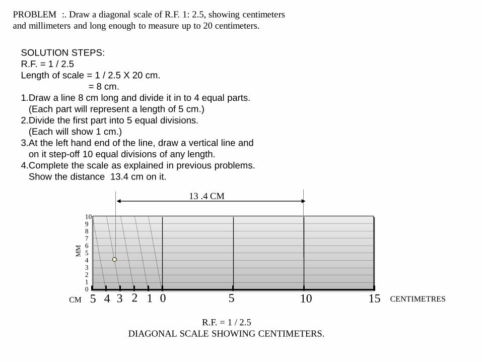
PROBLEM :. Draw a diagonal scale of R.F. 1: 2.5, showing centimeters
and millimeters and long enough to measure up to 20 centimeters.
SOLUTION STEPS:
R.F. = 1 / 2.5
Length of scale = 1 / 2.5 X 20 cm.
= 8 cm.
1.Draw a line 8 cm long and divide it in to 4 equal parts.
(Each part will represent a length of 5 cm.)
2.Divide the first part into 5 equal divisions.
(Each will show 1 cm.)
3.At the left hand end of the line, draw a vertical line and
on it step-off 10 equal divisions of any length.
4.Complete the scale as explained in previous problems.
Show the distance 13.4 cm on it.
13 .4 CM
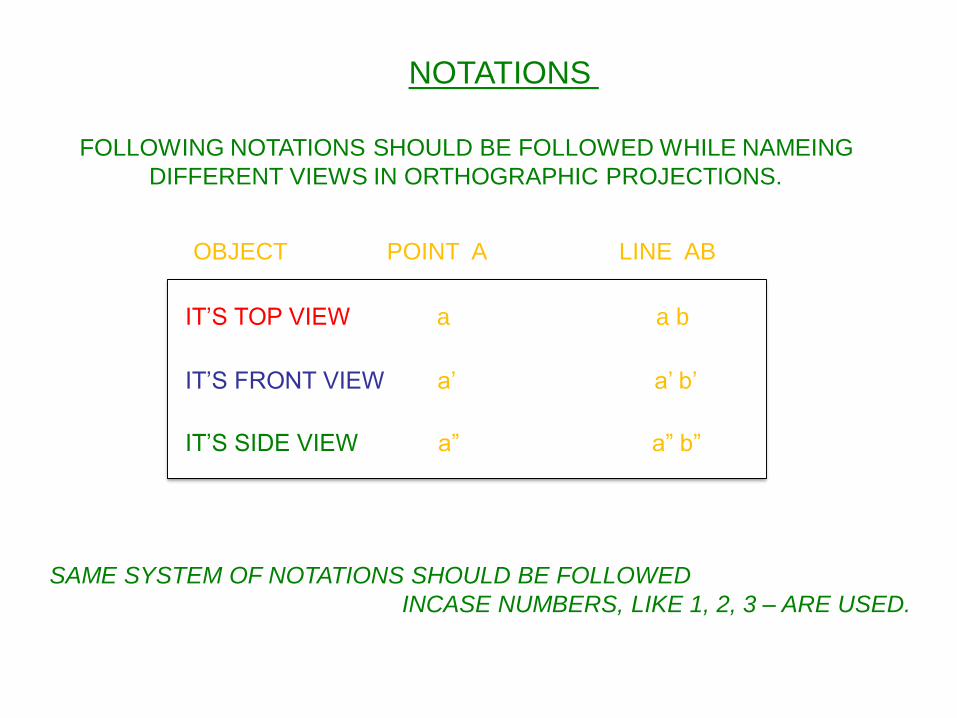
NOTATIONS
FOLLOWING NOTATIONS SHOULD BE FOLLOWED WHILE NAMEING
DIFFERENT VIEWS IN ORTHOGRAPHIC PROJECTIONS.
IT’S FRONT VIEW a’ a’ b’
SAME SYSTEM OF NOTATIONS SHOULD BE FOLLOWED
INCASE NUMBERS, LIKE 1, 2, 3 – ARE USED.
OBJECT POINT A LINE AB
IT’S TOP VIEW a a b
IT’S SIDE VIEW a” a” b”
PROJECTION OF
POINTS,LINES AND
PLANES
Prepared by
K. Mahesh
Asst. proff
Dept: mechanical
X
Y
1ST Quad.2nd Quad.
3rd Quad. 4th Quad.
X Y
VP
HP
Observer
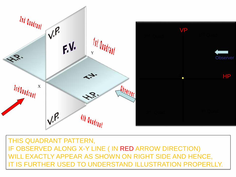
THIS QUADRANT PATTERN,
IF OBSERVED ALONG X-Y LINE ( IN RED ARROW DIRECTION)
WILL EXACTLY APPEAR AS SHOWN ON RIGHT SIDE AND HENCE,
IT IS FURTHER USED TO UNDERSTAND ILLUSTRATION PROPERLLY.
A
a
a’A
a
a’
Aa
a’
X
Y
X
Y
X
Y
For TvFor Tv
For Tv
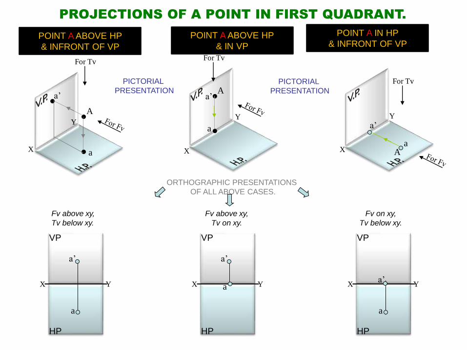
POINT A ABOVE HP
& INFRONT OF VP
POINT A IN HP
& INFRONT OF VPPOINT A ABOVE HP
& IN VP
PROJECTIONS OF A POINT IN FIRST QUADRANT.
PICTORIAL
PRESENTATIONPICTORIAL
PRESENTATION
ORTHOGRAPHIC PRESENTATIONS
OF ALL ABOVE CASES.
X Y
a
a’
VP
HP
X Y
a’
VP
HP
a X Y
a
VP
HP
a’
Fv above xy,
Tv below xy.
Fv above xy,
Tv on xy.
Fv on xy,
Tv below xy.
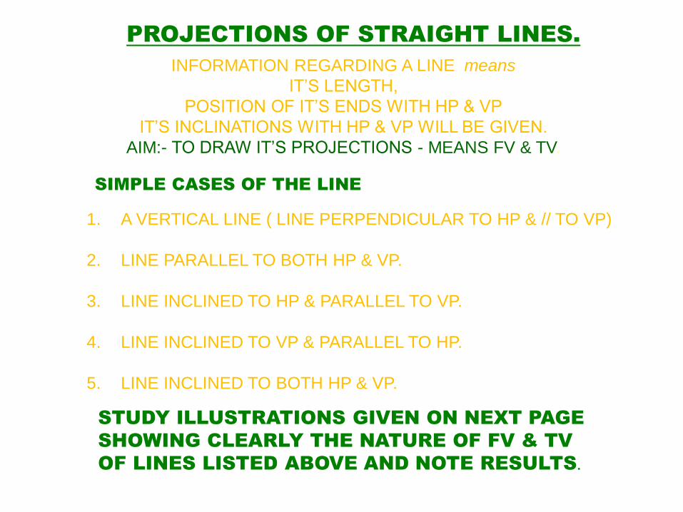
SIMPLE CASES OF THE LINE
1. A VERTICAL LINE ( LINE PERPENDICULAR TO HP & // TO VP)
2. LINE PARALLEL TO BOTH HP & VP.
3. LINE INCLINED TO HP & PARALLEL TO VP.
4. LINE INCLINED TO VP & PARALLEL TO HP.
5. LINE INCLINED TO BOTH HP & VP.
STUDY ILLUSTRATIONS GIVEN ON NEXT PAGE
SHOWING CLEARLY THE NATURE OF FV & TV
OF LINES LISTED ABOVE AND NOTE RESULTS.
PROJECTIONS OF STRAIGHT LINES.
INFORMATION REGARDING A LINE means
IT’S LENGTH,
POSITION OF IT’S ENDS WITH HP & VP
IT’S INCLINATIONS WITH HP & VP WILL BE GIVEN.
AIM:- TO DRAW IT’S PROJECTIONS - MEANS FV & TV.
X
Y
X
Y
b’
a’
b
a
a b
a’
b’
B
A
TV
FV
A
B
X Y
H.P.
V.P.a’
b’
a b
Fv
Tv
X Y
H.P.
V.P.
a b
a’ b’Fv
Tv
For Tv
For Tv
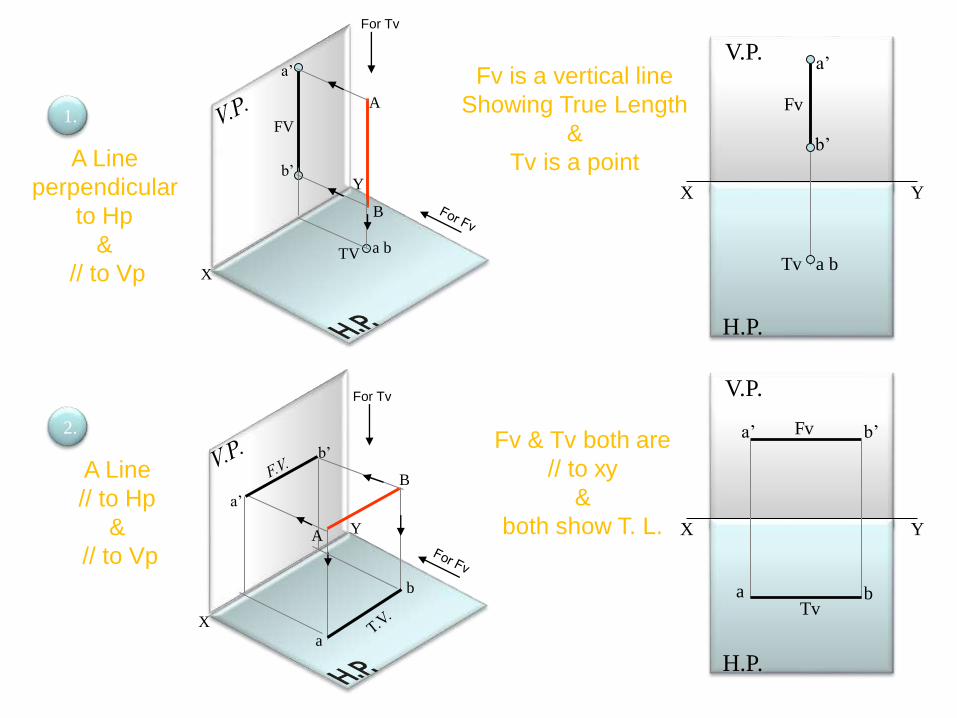
1.
2.
A Line
perpendicular
to Hp
&
// to Vp
A Line
// to Hp
&
// to Vp
Fv is a vertical line
Showing True Length
&
Tv is a point
Fv & Tv both are
// to xy
&
both show T. L.
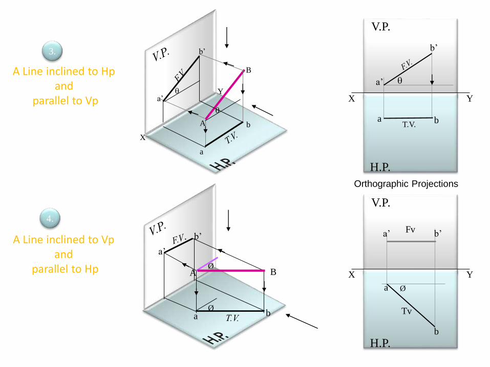
A Line inclined to Hp and
parallel to Vp
X
Y
A
B
b’
a’
b
a
A Line inclined to Vp and
parallel to Hp
Øa b
a’
b’
BAØ
X Y
H.P.
V.P.
T.V.a b
a’
b’
X Y
H.P.
V.P.
Øa
b
a’ b’
Tv
Fv
3.
4.
Orthographic Projections
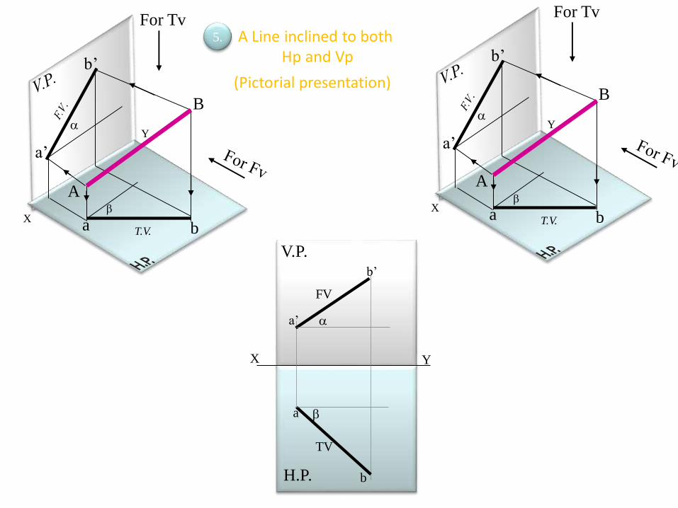
X
Y
a’
b’
a b
B
A
For Tv
T.V.
X
Y
a’
b’
a b
T.V.
For Tv
B
A
X Y
H.P.
V.P.
a
b
FV
TV
a’
b’
A Line inclined to bothHp and Vp
(Pictorial presentation)
5.
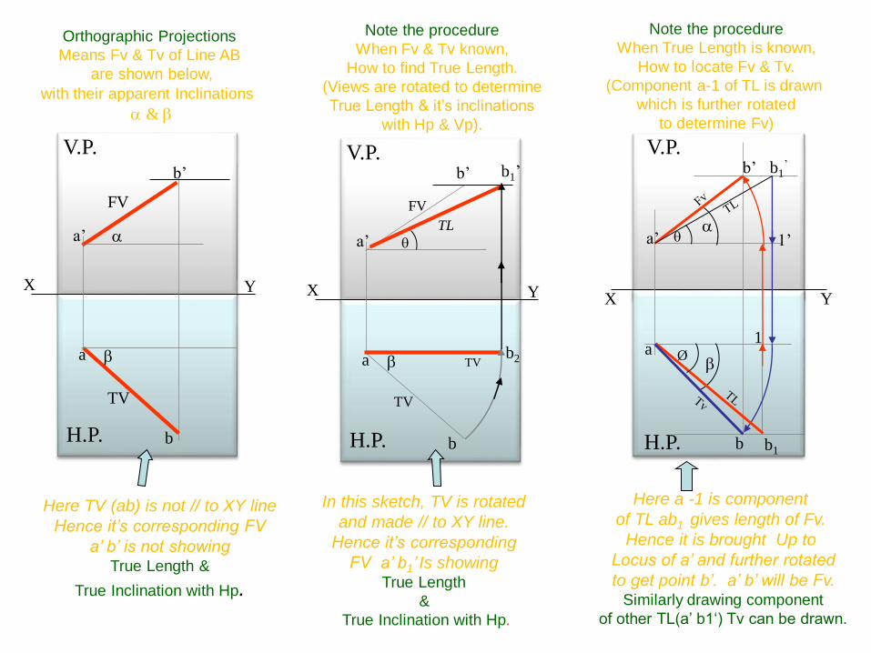
X Y
H.P.
V.P.
X Y
H.P.
V.P.
a
b
TV
a’
b’
FV
TV
b2
b1’
TL
X Y
H.P.
V.P.
a
b
FV
TV
a’
b’
Here TV (ab) is not // to XY line
Hence it’s corresponding FV
a’ b’ is not showing True Length &
True Inclination with Hp.
In this sketch, TV is rotated
and made // to XY line.
Hence it’s corresponding
FV a’ b1’ Is showing True Length
&
True Inclination with Hp.
Note the procedure
When Fv & Tv known,
How to find True Length.
(Views are rotated to determine
True Length & it’s inclinations
with Hp & Vp).
Note the procedure
When True Length is known,
How to locate Fv & Tv.
(Component a-1 of TL is drawn
which is further rotated
to determine Fv)
1a
a’
b’
1’
b
b1’
b1
Ø
Orthographic Projections
Means Fv & Tv of Line AB
are shown below,
with their apparent Inclinations
&
Here a -1 is component
of TL ab1 gives length of Fv.
Hence it is brought Up to
Locus of a’ and further rotated
to get point b’. a’ b’ will be Fv.Similarly drawing component
of other TL(a’ b1‘) Tv can be drawn.
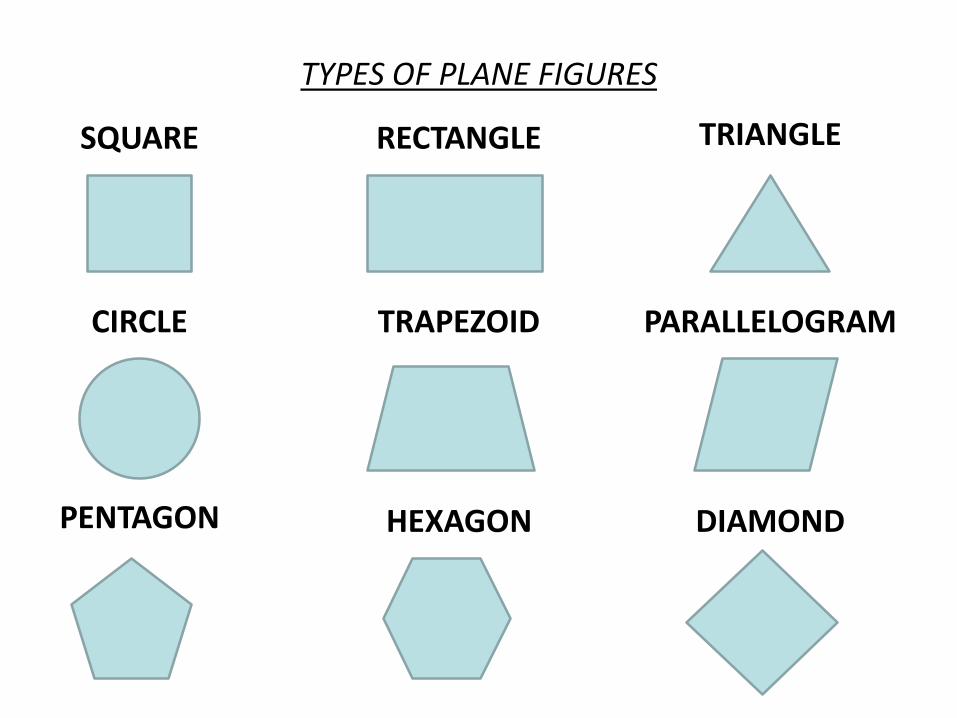
TYPES OF PLANE FIGURES
SQUARE RECTANGLE TRIANGLE
CIRCLE TRAPEZOID PARALLELOGRAM
PENTAGON HEXAGON DIAMOND
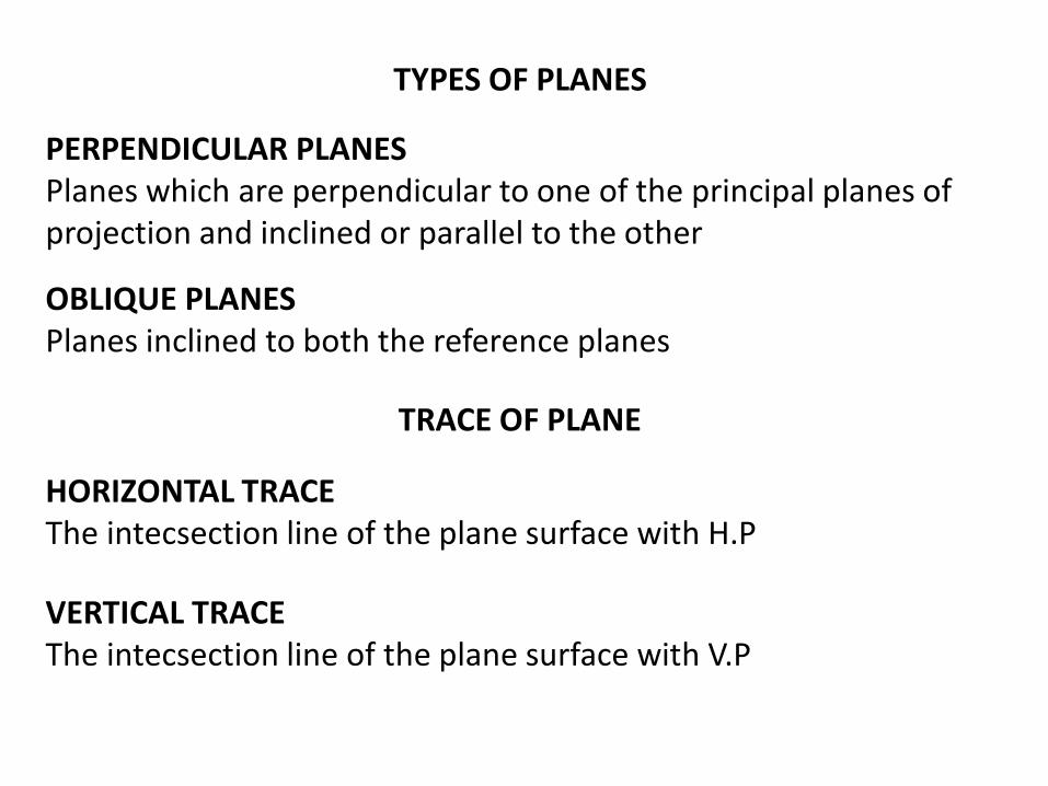
TYPES OF PLANES
PERPENDICULAR PLANESPlanes which are perpendicular to one of the principal planes of projection and inclined or parallel to the other
OBLIQUE PLANESPlanes inclined to both the reference planes
TRACE OF PLANE
HORIZONTAL TRACEThe intecsection line of the plane surface with H.P
VERTICAL TRACEThe intecsection line of the plane surface with V.P
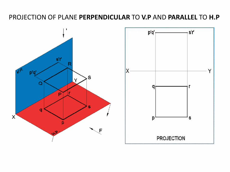
PROJECTION OF PLANE PERPENDICULAR TO V.P AND PARALLEL TO H.P
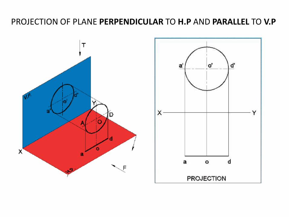
PROJECTION OF PLANE PERPENDICULAR TO H.P AND PARALLEL TO V.P
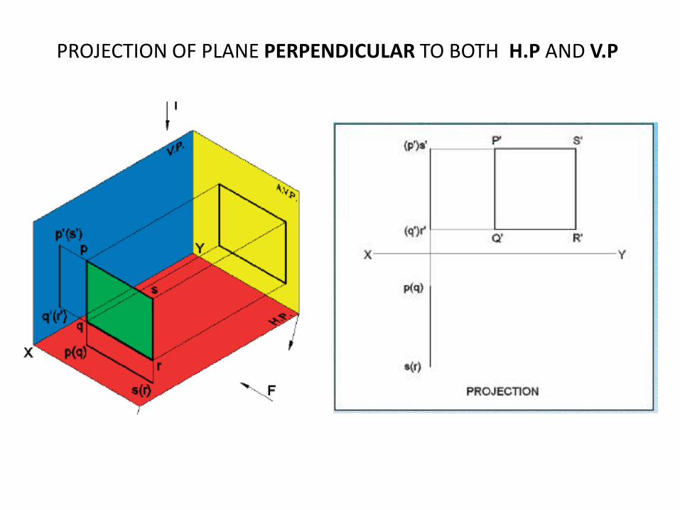
PROJECTION OF PLANE PERPENDICULAR TO BOTH H.P AND V.P
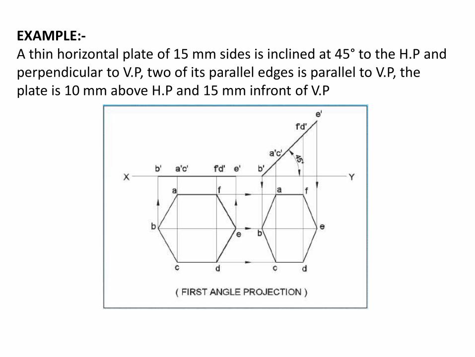
EXAMPLE:-A thin horizontal plate of 15 mm sides is inclined at 45° to the H.P and perpendicular to V.P, two of its parallel edges is parallel to V.P, the plate is 10 mm above H.P and 15 mm infront of V.P
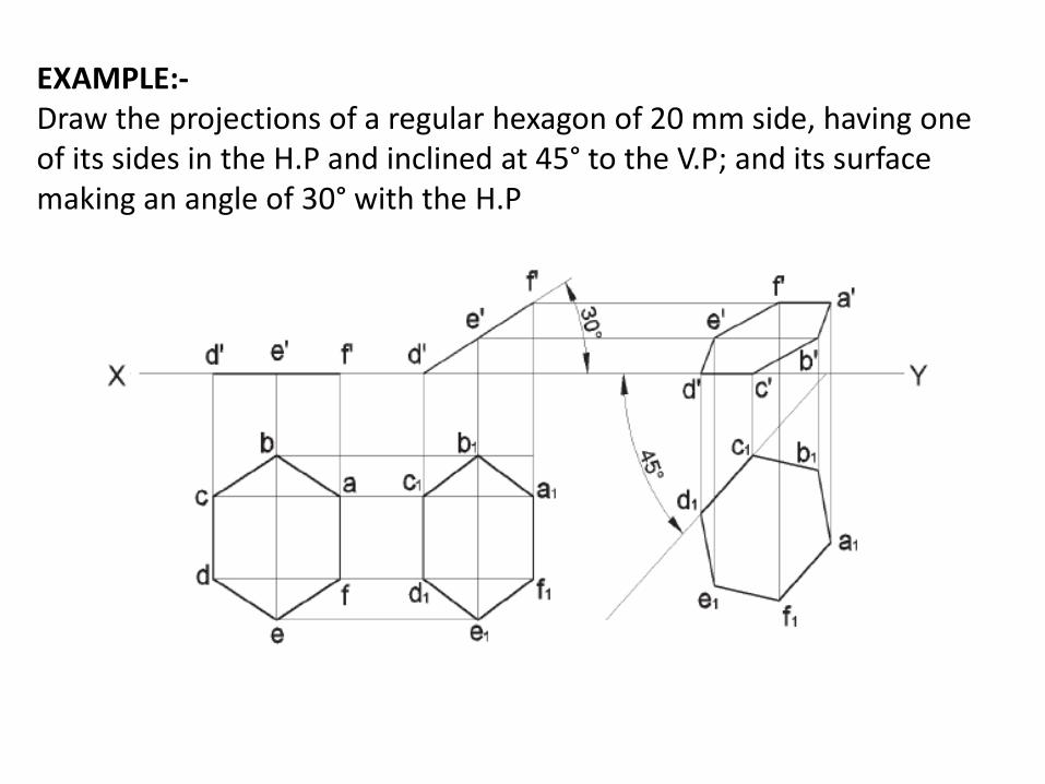
EXAMPLE:-Draw the projections of a regular hexagon of 20 mm side, having one of its sides in the H.P and inclined at 45° to the V.P; and its surface making an angle of 30° with the H.P
PROJECTION OF SOLIDS
Prepared by
K. Mahesh
Asst. proff
Dept: mechanical
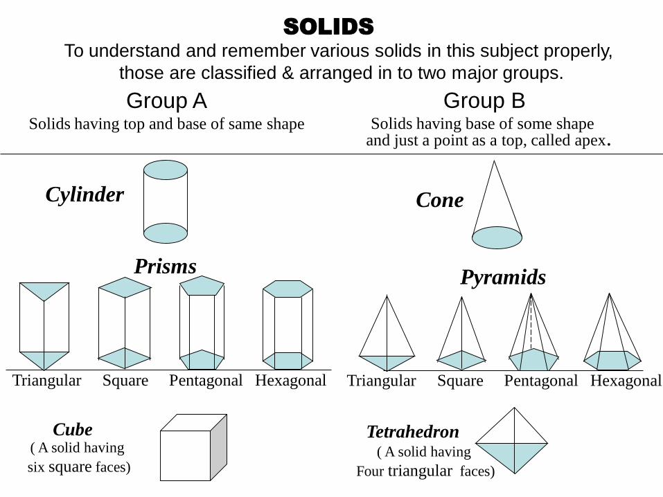
SOLIDSTo understand and remember various solids in this subject properly,
those are classified & arranged in to two major groups.
Group ASolids having top and base of same shape
Cylinder
Prisms
Triangular Square Pentagonal Hexagonal
Cube
Triangular Square Pentagonal Hexagonal
Cone
Tetrahedron
Pyramids
( A solid having
six square faces)( A solid having
Four triangular faces)
Group BSolids having base of some shape
and just a point as a top, called apex.
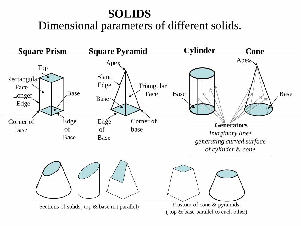
SOLIDSDimensional parameters of different solids.
Top
Rectangular
Face
Longer
Edge
Base
Edge
of
Base
Corner of
base
Corner of
base
Triangular
Face
Slant
Edge
Base
Apex
Square Prism Square Pyramid Cylinder Cone
Edge
of
Base
Base
Apex
Base
Generators
Imaginary lines
generating curved surface
of cylinder & cone.
Sections of solids( top & base not parallel) Frustum of cone & pyramids.
( top & base parallel to each other)
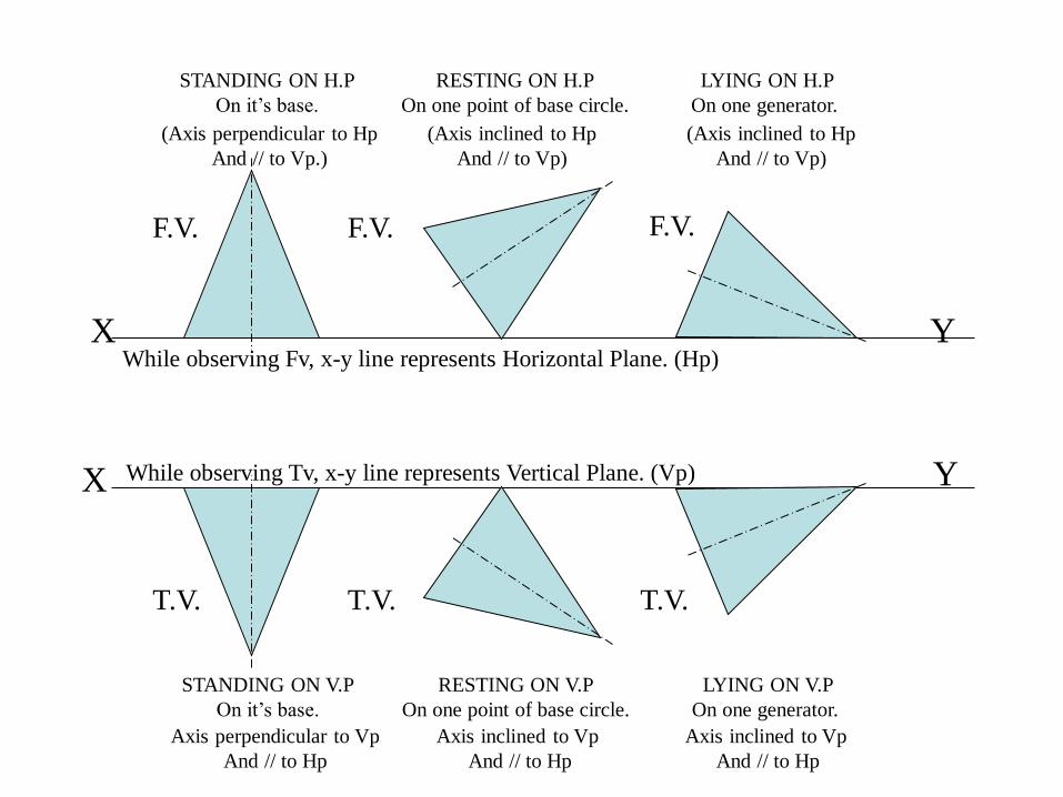
X Y
STANDING ON H.P
On it’s base.
RESTING ON H.P
On one point of base circle.
LYING ON H.P
On one generator.
(Axis perpendicular to Hp
And // to Vp.)
(Axis inclined to Hp
And // to Vp)
(Axis inclined to Hp
And // to Vp)
While observing Fv, x-y line represents Horizontal Plane. (Hp)
Axis perpendicular to Vp
And // to Hp
Axis inclined to Vp
And // to Hp
Axis inclined to Vp
And // to Hp
X Y
F.V. F.V. F.V.
T.V. T.V. T.V.
While observing Tv, x-y line represents Vertical Plane. (Vp)
STANDING ON V.P
On it’s base.
RESTING ON V.P
On one point of base circle.
LYING ON V.P
On one generator.
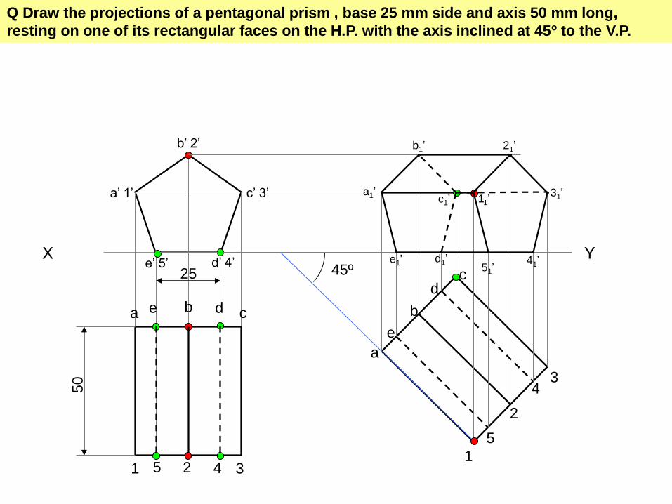
Q Draw the projections of a pentagonal prism , base 25 mm side and axis 50 mm long,
resting on one of its rectangular faces on the H.P. with the axis inclined at 45º to the V.P.
X Y
a’ 1’
b’ 2’
c’ 3’
d’ 4’e’ 5’25
50
a b cde
1 2 35 4
45º
a
b
cd
e
1
2
3
5
4
a1’
b1’
c1’
d1’e1’
11’
21’
31’
41’51’
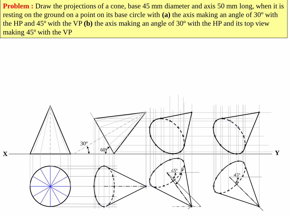
Problem : Draw the projections of a cone, base 45 mm diameter and axis 50 mm long, when it is
resting on the ground on a point on its base circle with (a) the axis making an angle of 30º with
the HP and 45º with the VP (b) the axis making an angle of 30º with the HP and its top view
making 45º with the VP
X Y60º
30º
45º45º

X
b 2
c 3
d 4
a 1
a’ d’ c’b’
3’3’1’ 2’ 4’
2’ 4’
3’
Y
a1
b1
c1
d1
11
21
31
41
b1
c1
d1
11
21 41
c1’
b1’ d1’
31’
11’
a1’
21’ 41’
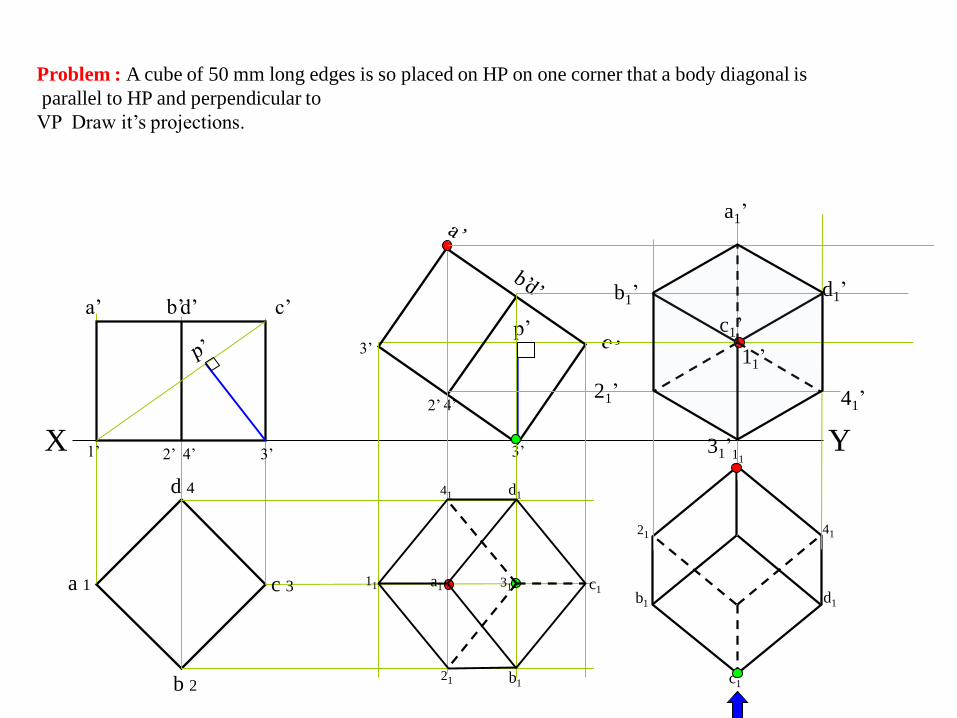
Problem : A cube of 50 mm long edges is so placed on HP on one corner that a body diagonal is
parallel to HP and perpendicular to
VP Draw it’s projections.
X
b 2
c 3
d 4
a 1
a’ d’ c’b’
3’3’1’ 2’ 4’
2’ 4’
3’
Y
a1
b1
c1
d1
11
21
31
41
b1
c1
d1
11
21 41
c1’
b1’ d1’
31’
11’
a1’
21’ 41’
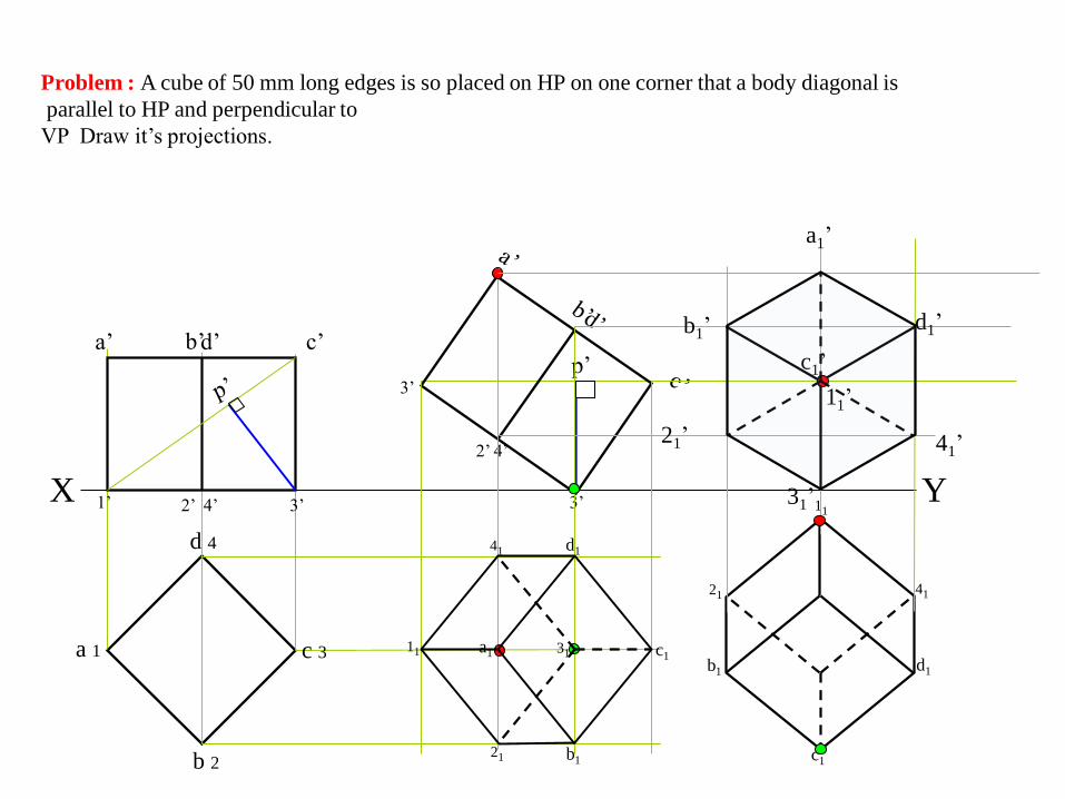
Problem : A cube of 50 mm long edges is so placed on HP on one corner that a body diagonal is
parallel to HP and perpendicular to
VP Draw it’s projections.
X
b 2
c 3
d 4
a 1
a’ d’ c’b’
3’3’1’ 2’ 4’
2’ 4’
3’
Y
a1
b1
c1
d1
11
21
31
41
b1
c1
d1
11
21 41
c1’
b1’ d1’
31’
11’
a1’
21’ 41’
Problem : A cube of 50 mm long edges is so placed on HP on one corner that a body diagonal is
parallel to HP and perpendicular to
VP Draw it’s projections.
SECTION OF SOLID AND
DEVELOPMENT OF
SURPHASES
Prepared by
K. Mahesh
Asst. proff
Dept: mechanical
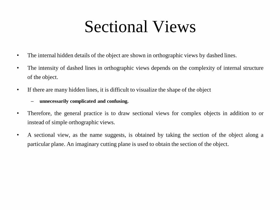
Sectional Views
• The internal hidden details of the object are shown in orthographic views by dashed lines.
• The intensity of dashed lines in orthographic views depends on the complexity of internal structure
of the object.
• If there are many hidden lines, it is difficult to visualize the shape of the object
– unnecessarily complicated and confusing.
• Therefore, the general practice is to draw sectional views for complex objects in addition to or
instead of simple orthographic views.
• A sectional view, as the name suggests, is obtained by taking the section of the object along a
particular plane. An imaginary cutting plane is used to obtain the section of the object.
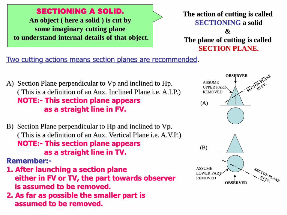
SECTIONING A SOLID.
An object ( here a solid ) is cut by
some imaginary cutting plane
to understand internal details of that object.
The action of cutting is called
SECTIONING a solid
&
The plane of cutting is called
SECTION PLANE.
Two cutting actions means section planes are recommended.
A) Section Plane perpendicular to Vp and inclined to Hp.
( This is a definition of an Aux. Inclined Plane i.e. A.I.P.)
NOTE:- This section plane appears
as a straight line in FV.
B) Section Plane perpendicular to Hp and inclined to Vp.
( This is a definition of an Aux. Vertical Plane i.e. A.V.P.)
NOTE:- This section plane appears
as a straight line in TV.Remember:-1. After launching a section plane
either in FV or TV, the part towards observeris assumed to be removed.
2. As far as possible the smaller part is assumed to be removed.
OBSERVER
ASSUME
UPPER PART
REMOVED
OBSERVER
ASSUME
LOWER PART
REMOVED
(A)
(B)
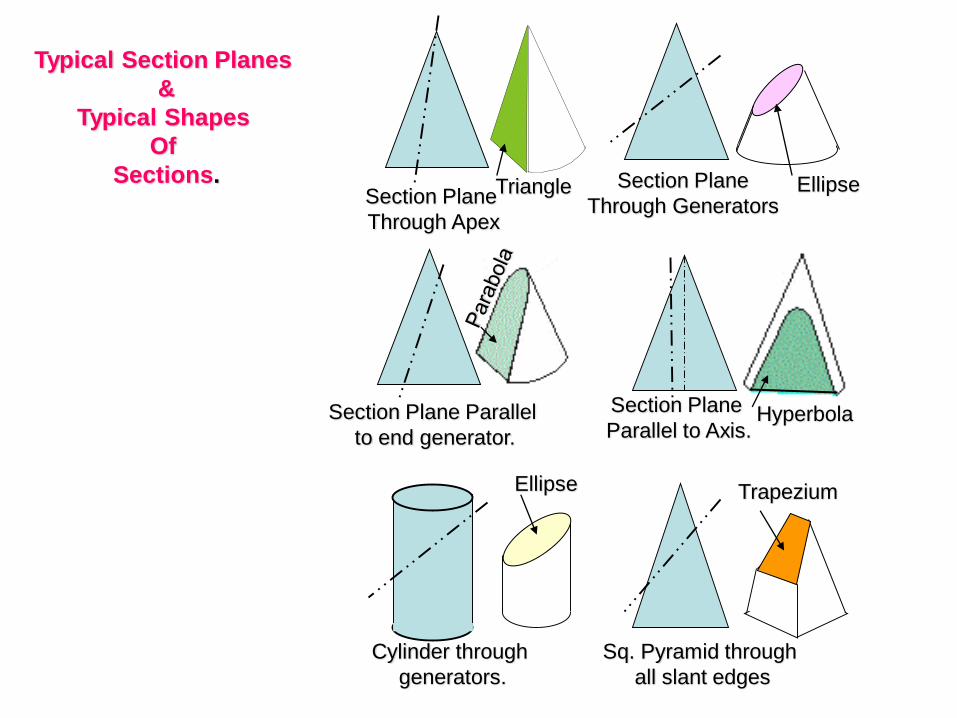
Section Plane
Through Apex
Section Plane
Through Generators
Section Plane Parallel
to end generator.
Section Plane
Parallel to Axis.
Triangle Ellipse
Hyperbola
Ellipse
Cylinder through
generators.
Sq. Pyramid through
all slant edges
Trapezium
Typical Section Planes
&
Typical Shapes
Of
Sections.
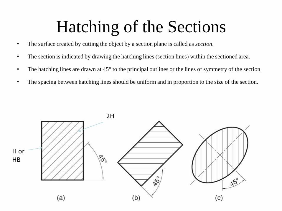
Hatching of the Sections• The surface created by cutting the object by a section plane is called as section.
• The section is indicated by drawing the hatching lines (section lines) within the sectioned area.
• The hatching lines are drawn at 45° to the principal outlines or the lines of symmetry of the section
• The spacing between hatching lines should be uniform and in proportion to the size of the section.
H orHB
2H
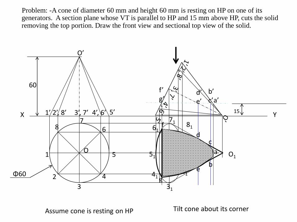
Problem: -A cone of diameter 60 mm and height 60 mm is resting on HP on one of its generators. A section plane whose VT is parallel to HP and 15 mm above HP, cuts the solid removing the top portion. Draw the front view and sectional top view of the solid.
X Y
Assume cone is resting on HP
1
2
3
4
5
67
8
O
Φ60
60
1’ 2’, 8’ 3’, 7’ 4’, 6’ 5’
O’
Tilt cone about its corner
51
41
31
21
11
81
71
61
O1
a’b’c’
d’e’
f’g’
a
c
b
d
e
f
g
15
X
Y
X1
Y1
A
B
C
E
D
a
e
d
b
c
a”
b”
c”d”
e”
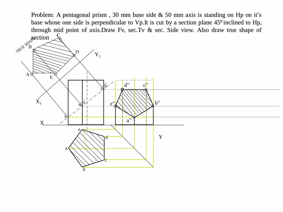
Problem: A pentagonal prism , 30 mm base side & 50 mm axis is standing on Hp on it’s
base whose one side is perpendicular to Vp.It is cut by a section plane 450 inclined to Hp,
through mid point of axis.Draw Fv, sec.Tv & sec. Side view. Also draw true shape of
section
X Y
1
2
34
5
6
7
8
910
11
12
12
12
3 11
4 10
5 9
6 8 7
o
o’
35
a
b
k
cd
l
e
f
g
h
i
j
a’
b’
k’c’
d’
l’
e’f’g’
h’i’
j’
X1
Y1
4” 5” 6” 7” 8” 9”10”11”12”1”2”3”
o”
a”
b”
c”
d”
e”
f”g”
h”
i”
j”
k”
l”
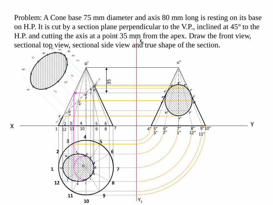
Problem: A Cone base 75 mm diameter and axis 80 mm long is resting on its base
on H.P. It is cut by a section plane perpendicular to the V.P., inclined at 45º to the
H.P. and cutting the axis at a point 35 mm from the apex. Draw the front view,
sectional top view, sectional side view and true shape of the section.
D
H
D
SS
H
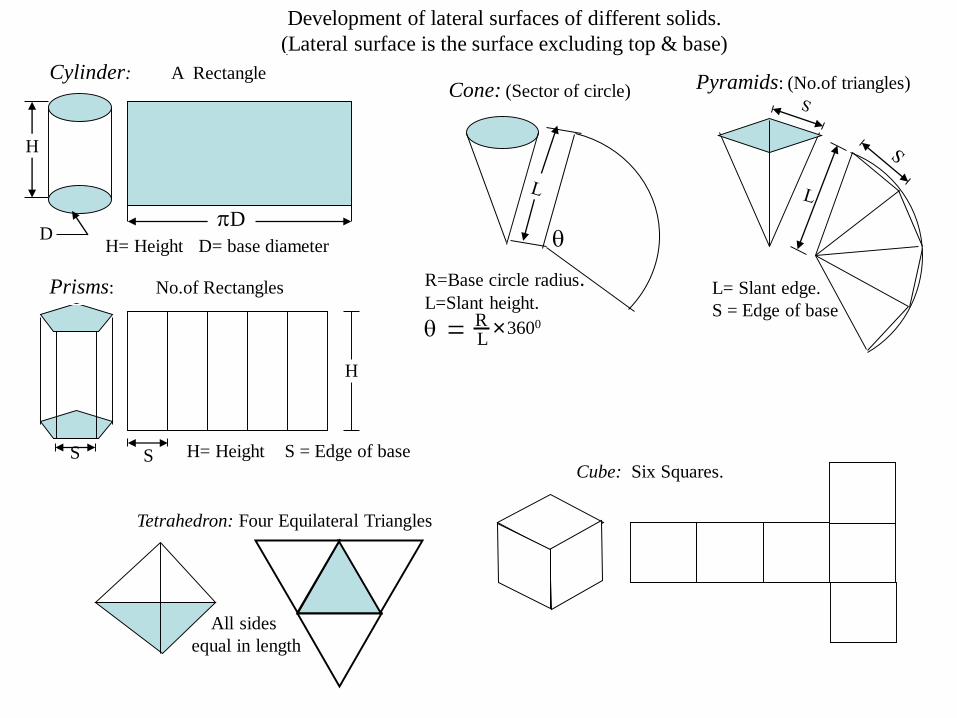
= RL
3600
R=Base circle radius.L=Slant height.
L= Slant edge.
S = Edge of base
H= Height S = Edge of base
H= Height D= base diameter
Development of lateral surfaces of different solids.
(Lateral surface is the surface excluding top & base)
Prisms: No.of Rectangles
Cylinder: A RectangleCone: (Sector of circle) Pyramids: (No.of triangles)
Tetrahedron: Four Equilateral Triangles
All sides
equal in length
Cube: Six Squares.
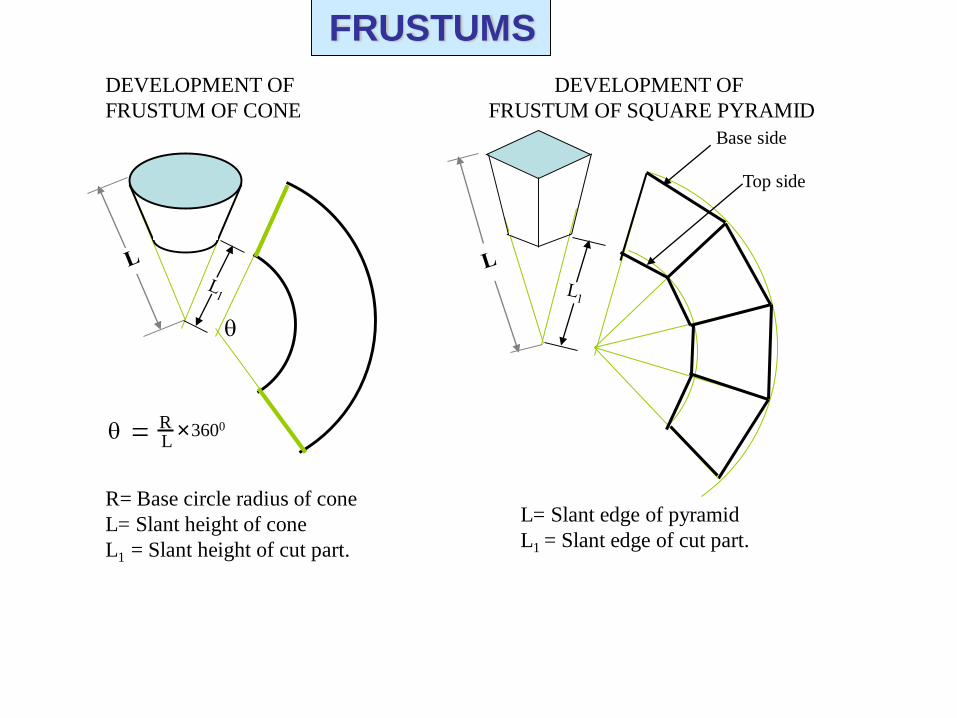
= RL
3600
R= Base circle radius of cone
L= Slant height of cone
L1 = Slant height of cut part.
Base side
Top side
L= Slant edge of pyramid
L1 = Slant edge of cut part.
DEVELOPMENT OF
FRUSTUM OF CONE
DEVELOPMENT OF
FRUSTUM OF SQUARE PYRAMID
FRUSTUMS
Y
h
a
b
c
d
e
g
f
X a’ b’ d’ e’c’ g’ f’h’
o’
X1
Y1
g” h”f” a”e” b”d” c”
A
B
C
D
E
F
A
G
H
SECTIONAL T.V
SECTIONAL S.V
DEVELOPMENT
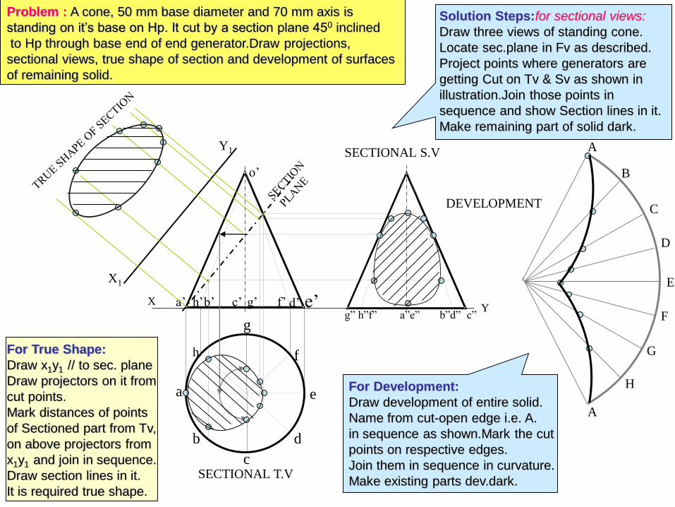
Problem : A cone, 50 mm base diameter and 70 mm axis is
standing on it’s base on Hp. It cut by a section plane 450 inclined
to Hp through base end of end generator.Draw projections,
sectional views, true shape of section and development of surfaces
of remaining solid.
Solution Steps:for sectional views:
Draw three views of standing cone.
Locate sec.plane in Fv as described.
Project points where generators are
getting Cut on Tv & Sv as shown in
illustration.Join those points in
sequence and show Section lines in it.
Make remaining part of solid dark.
For True Shape:
Draw x1y1 // to sec. plane
Draw projectors on it from
cut points.
Mark distances of points
of Sectioned part from Tv,
on above projectors from
x1y1 and join in sequence.
Draw section lines in it.
It is required true shape.
For Development:
Draw development of entire solid.
Name from cut-open edge i.e. A.
in sequence as shown.Mark the cut
points on respective edges.
Join them in sequence in curvature.
Make existing parts dev.dark.
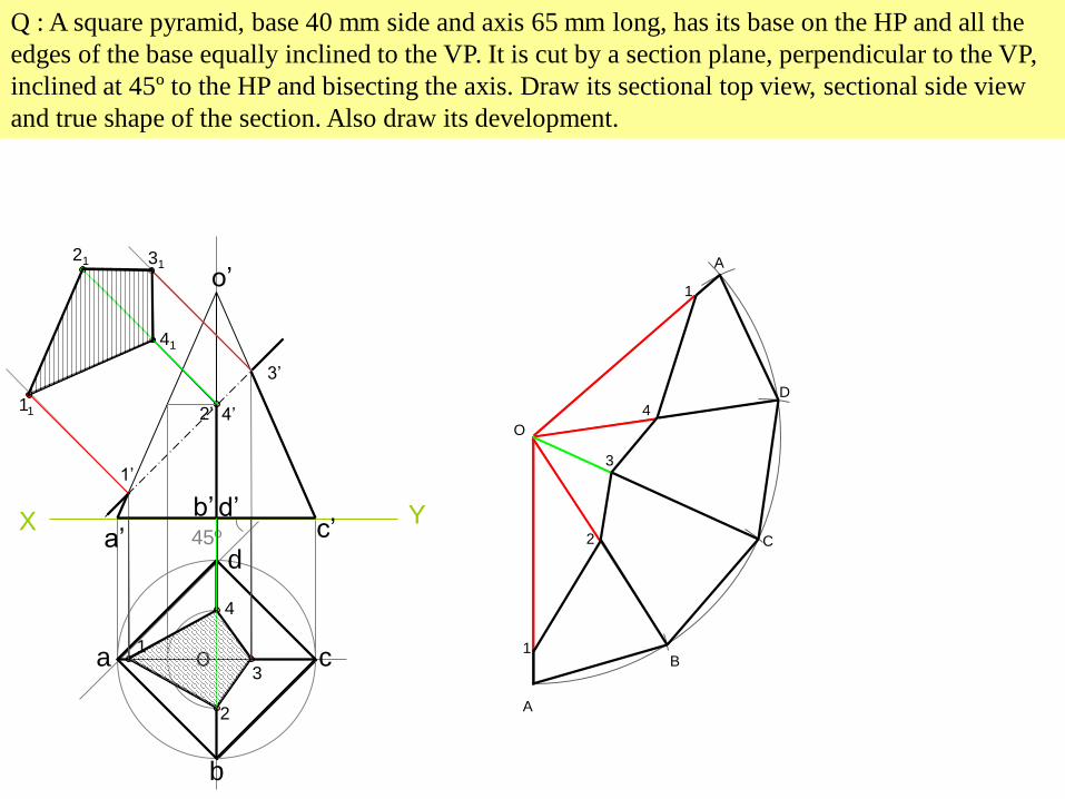
Q : A square pyramid, base 40 mm side and axis 65 mm long, has its base on the HP and all the
edges of the base equally inclined to the VP. It is cut by a section plane, perpendicular to the VP,
inclined at 45º to the HP and bisecting the axis. Draw its sectional top view, sectional side view
and true shape of the section. Also draw its development.
X45º
a
b
c
d
o
a’
b’c’
d’
o’
1
2
3
4
1’
2’
3’
4’11
41
21 31
Y
A
B
C
D
A
O
1
1
2
3
4
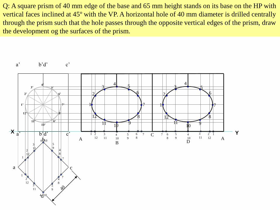
Q: A square prism of 40 mm edge of the base and 65 mm height stands on its base on the HP with
vertical faces inclined at 45º with the VP. A horizontal hole of 40 mm diameter is drilled centrally
through the prism such that the hole passes through the opposite vertical edges of the prism, draw
the development og the surfaces of the prism.
YX
a
b
c
d
a’ b’d’ c’
a’ b’d’ c’
1’
2’
3’4’
5’
6’
7’
8’
9’10’
11’
12’
1
1
2
12
2
12
3
11
3
11
4 10
4 10
5
9
5
9
4
8
4
8
1 2
123
114
10AB
C
7
7
5
9
6
87 6
8
5
94
10
7 12
12
3
11 A
1
2
12
11
3
10
4
9
5
8
6
7 1
2
12
11 9
5
8
7
34
6
10
D